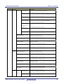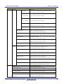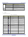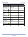
1
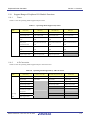
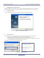
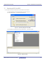
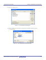
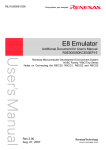
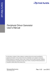
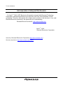
To our customers, Old Company Name in Catalogs and Other Documents On April 1st, 2010, NEC Electronics Corporation merged with Renesas Technology Corporation, and Renesas Electronics Corporation took over all the business of both companies. Therefore, although the old company name remains in this document, it is a valid Renesas Electronics document. We appreciate your understanding. Renesas Electronics website: http://www.renesas.com April 1st, 2010 Renesas Electronics Corporation Issued by: Renesas Electronics Corporation (http://www.renesas.com) Send any inquiries to http://www.renesas.com/inquiry. Notice 1. 2. 3. 4. 5. 6. 7. All information included in this document is current as of the date this document is issued. Such information, however, is subject to change without any prior notice. Before purchasing or using any Renesas Electronics products listed herein, please confirm the latest product information with a Renesas Electronics sales office. Also, please pay regular and careful attention to additional and different information to be disclosed by Renesas Electronics such as that disclosed through our website. Renesas Electronics does not assume any liability for infringement of patents, copyrights, or other intellectual property rights of third parties by or arising from the use of Renesas Electronics products or technical information described in this document. No license, express, implied or otherwise, is granted hereby under any patents, copyrights or other intellectual property rights of Renesas Electronics or others. You should not alter, modify, copy, or otherwise misappropriate any Renesas Electronics product, whether in whole or in part. Descriptions of circuits, software and other related information in this document are provided only to illustrate the operation of semiconductor products and application examples. You are fully responsible for the incorporation of these circuits, software, and information in the design of your equipment. Renesas Electronics assumes no responsibility for any losses incurred by you or third parties arising from the use of these circuits, software, or information. When exporting the products or technology described in this document, you should comply with the applicable export control laws and regulations and follow the procedures required by such laws and regulations. You should not use Renesas Electronics products or the technology described in this document for any purpose relating to military applications or use by the military, including but not limited to the development of weapons of mass destruction. Renesas Electronics products and technology may not be used for or incorporated into any products or systems whose manufacture, use, or sale is prohibited under any applicable domestic or foreign laws or regulations. Renesas Electronics has used reasonable care in preparing the information included in this document, but Renesas Electronics does not warrant that such information is error free. Renesas Electronics assumes no liability whatsoever for any damages incurred by you resulting from errors in or omissions from the information included herein. Renesas Electronics products are classified according to the following three quality grades: “Standard”, “High Quality”, and “Specific”. The recommended applications for each Renesas Electronics product depends on the product’s quality grade, as indicated below. You must check the quality grade of each Renesas Electronics product before using it in a particular application. You may not use any Renesas Electronics product for any application categorized as “Specific” without the prior written consent of Renesas Electronics. Further, you may not use any Renesas Electronics product for any application for which it is not intended without the prior written consent of Renesas Electronics. Renesas Electronics shall not be in any way liable for any damages or losses incurred by you or third parties arising from the use of any Renesas Electronics product for an application categorized as “Specific” or for which the product is not intended where you have failed to obtain the prior written consent of Renesas Electronics. The quality grade of each Renesas Electronics product is “Standard” unless otherwise expressly specified in a Renesas Electronics data sheets or data books, etc. “Standard”: 8. 9. 10. 11. 12. Computers; office equipment; communications equipment; test and measurement equipment; audio and visual equipment; home electronic appliances; machine tools; personal electronic equipment; and industrial robots. “High Quality”: Transportation equipment (automobiles, trains, ships, etc.); traffic control systems; anti-disaster systems; anticrime systems; safety equipment; and medical equipment not specifically designed for life support. “Specific”: Aircraft; aerospace equipment; submersible repeaters; nuclear reactor control systems; medical equipment or systems for life support (e.g. artificial life support devices or systems), surgical implantations, or healthcare intervention (e.g. excision, etc.), and any other applications or purposes that pose a direct threat to human life. You should use the Renesas Electronics products described in this document within the range specified by Renesas Electronics, especially with respect to the maximum rating, operating supply voltage range, movement power voltage range, heat radiation characteristics, installation and other product characteristics. Renesas Electronics shall have no liability for malfunctions or damages arising out of the use of Renesas Electronics products beyond such specified ranges. Although Renesas Electronics endeavors to improve the quality and reliability of its products, semiconductor products have specific characteristics such as the occurrence of failure at a certain rate and malfunctions under certain use conditions. Further, Renesas Electronics products are not subject to radiation resistance design. Please be sure to implement safety measures to guard them against the possibility of physical injury, and injury or damage caused by fire in the event of the failure of a Renesas Electronics product, such as safety design for hardware and software including but not limited to redundancy, fire control and malfunction prevention, appropriate treatment for aging degradation or any other appropriate measures. Because the evaluation of microcomputer software alone is very difficult, please evaluate the safety of the final products or system manufactured by you. Please contact a Renesas Electronics sales office for details as to environmental matters such as the environmental compatibility of each Renesas Electronics product. Please use Renesas Electronics products in compliance with all applicable laws and regulations that regulate the inclusion or use of controlled substances, including without limitation, the EU RoHS Directive. Renesas Electronics assumes no liability for damages or losses occurring as a result of your noncompliance with applicable laws and regulations. This document may not be reproduced or duplicated, in any form, in whole or in part, without prior written consent of Renesas Electronics. Please contact a Renesas Electronics sales office if you have any questions regarding the information contained in this document or Renesas Electronics products, or if you have any other inquiries. (Note 1) “Renesas Electronics” as used in this document means Renesas Electronics Corporation and also includes its majorityowned subsidiaries. (Note 2) “Renesas Electronics product(s)” means any product developed or manufactured by or for Renesas Electronics. User’s Manual Peripheral Driver Generator V.1.02 User’s Manual Rev.1.00 2007.11 Notes regarding these materials 1. This document is provided for reference purposes only so that Renesas customers may select the appropriate Renesas products for their use. Renesas neither makes warranties or representations with respect to the accuracy or completeness of the information contained in this document nor grants any license to any intellectual property rights or any other rights of Renesas or any third party with respect to the information in this document. 2. Renesas shall have no liability for damages or infringement of any intellectual property or other rights arising out of the use of any information in this document, including, but not limited to, product data, diagrams, charts, programs, algorithms, and application circuit examples. 3. You should not use the products or the technology described in this document for the purpose of military applications such as the development of weapons of mass destruction or for the purpose of any other military use. When exporting the products or technology described herein, you should follow the applicable export control laws and regulations, and procedures required by such laws and regulations. 4. All information included in this document such as product data, diagrams, charts, programs, algorithms, and application circuit examples, is current as of the date this document is issued. Such information, however, is subject to change without any prior notice. Before purchasing or using any Renesas products listed in this document, please confirm the latest product information with a Renesas sales office. Also, please pay regular and careful attention to additional and different information to be disclosed by Renesas such as that disclosed through our website. (http://www.renesas.com ) 5. Renesas has used reasonable care in compiling the information included in this document, but Renesas assumes no liability whatsoever for any damages incurred as a result of errors or omissions in the information included in this document. 6. When using or otherwise relying on the information in this document, you should evaluate the information in light of the total system before deciding about the applicability of such information to the intended application. Renesas makes no representations, warranties or guaranties regarding the suitability of its products for any particular application and specifically disclaims any liability arising out of the application and use of the information in this document or Renesas products. 7. With the exception of products specified by Renesas as suitable for automobile applications, Renesas products are not designed, manufactured or tested for applications or otherwise in systems the failure or malfunction of which may cause a direct threat to human life or create a risk of human injury or which require especially high quality and reliability such as safety systems, or equipment or systems for transportation and traffic, healthcare, combustion control, aerospace and aeronautics, nuclear power, or undersea communication transmission. If you are considering the use of our products for such purposes, please contact a Renesas sales office beforehand. Renesas shall have no liability for damages arising out of the uses set forth above. 8. Notwithstanding the preceding paragraph, you should not use Renesas products for the purposes listed below: (1) artificial life support devices or systems (2) surgical implantations (3) healthcare intervention (e.g., excision, administration of medication, etc.) (4) any other purposes that pose a direct threat to human life Renesas shall have no liability for damages arising out of the uses set forth in the above and purchasers who elect to use Renesas products in any of the foregoing applications shall indemnify and hold harmless Renesas Technology Corp., its affiliated companies and their officers, directors, and employees against any and all damages arising out of such applications. 9. You should use the products described herein within the range specified by Renesas, especially with respect to the maximum rating, operating supply voltage range, movement power voltage range, heat radiation characteristics, installation and other product characteristics. Renesas shall have no liability for malfunctions or damages arising out of the use of Renesas products beyond such specified ranges. 10. Although Renesas endeavors to improve the quality and reliability of its products, IC products have specific characteristics such as the occurrence of failure at a certain rate and malfunctions under certain use conditions. Please be sure to implement safety measures to guard against the possibility of physical injury, and injury or damage caused by fire in the event of the failure of a Renesas product, such as safety design for hardware and software including but not limited to redundancy, fire control and malfunction prevention, appropriate treatment for aging degradation or any other applicable measures. Among others, since the evaluation of microcomputer software alone is very difficult, please evaluate the safety of the final products or system manufactured by you. 11. In case Renesas products listed in this document are detached from the products to which the Renesas products are attached or affixed, the risk of accident such as swallowing by infants and small children is very high. You should implement safety measures so that Renesas products may not be easily detached from your products. Renesas shall have no liability for damages arising out of such detachment. 12. This document may not be reproduced or duplicated, in any form, in whole or in part, without prior written approval from Renesas. 13. Please contact a Renesas sales office if you have any questions regarding the information contained in this document, Renesas semiconductor products, or if you have any other inquiries. For inquiries about the contents of this document or product, fill in the text file the installer generates in the following directory and email to your local distributor. \SUPPORT\Product-name\SUPPORT.TXT Renesas Tools Homepage http://www.renesas.com/en/tools Peripheral Driver Generator Preface The Peripheral Driver Generator (hereafter referred to as PDG) is a tool that supports the development of a driver for a peripheral I/O module in a microcomputer. The PDG, which contains peripheral I/O module API libraries, allows users to design and automatically generate functions for calling the libraries via its user interface. It runs on a Microsoft Windows operating system with an IBM PC compatible machine. The supported microcomputers are the H8/Tiny, R8C/Tiny, and M16C/Tiny series, and main groups of the M16C/60 series. For details, refer to “Overview” in this manual. Usage Precautions Even though we carefully evaluate the API libraries and functions generated by the PDG, fully examine your application on your own responsibility when using this software to develop your application. IBM is a registered trademark of International Business Machines Corporation. Microsoft and Windows are registered trademarks of Microsoft Corporation in the United States and other countries. All brand or product names used in this manual are trademarks or registered trademarks of their respective companies or organizations. REJ10J1769-0100 Rev.1.00 Nov. 28, 2007 i Peripheral Driver Generator REJ10J1769-0100 Rev.1.00 Nov. 28, 2007 ii Peripheral Driver Generator Contents 1. 2. 3. Overview...................................................................................................................................................................1-1 1.1 PDG Features.....................................................................................................................................................1-1 1.2 PDG Project .......................................................................................................................................................1-1 1.3 Roles of the PDG ...............................................................................................................................................1-2 1.4 Operating Environment......................................................................................................................................1-2 1.5 Compiler Combinations .....................................................................................................................................1-3 1.6 API Libraries......................................................................................................................................................1-3 1.7 Main Window ....................................................................................................................................................1-4 1.7.1 Setting Details Display Window................................................................................................................1-4 1.7.2 New Setup Pattern Creation Window ........................................................................................................1-5 1.7.3 Generated File Information Window .........................................................................................................1-5 1.8 Menu ..................................................................................................................................................................1-7 1.9 Toolbar............................................................................................................................................................. 1-10 1.10 Support Range of Peripheral I/O Module Functions........................................................................................ 1-12 1.10.1 Timer........................................................................................................................................................ 1-12 1.10.2 A/D Conversion ....................................................................................................................................... 1-12 Preparation for Using the PDG ..............................................................................................................................2-1 2.1 Installing the PDG .............................................................................................................................................2-1 2.2 Setting an Editor ................................................................................................................................................2-1 2.3 Registering the PDG in the HEW ......................................................................................................................2-2 2.4 Setting HewTargetServer...................................................................................................................................2-4 How to Operate the PDG ........................................................................................................................................3-1 3.1 Developing an Application with the PDG .........................................................................................................3-1 3.2 PDG Operation Flow .........................................................................................................................................3-2 3.3 Creating/Opening a Project................................................................................................................................3-3 3.3.1 Creating a New Project ..............................................................................................................................3-3 3.3.2 Opening an Existing Project ......................................................................................................................3-6 3.3.3 Setting CPU Clocks ...................................................................................................................................3-7 3.4 Selecting/Setting Peripheral I/O Modules..........................................................................................................3-8 3.4.1 Creating a New Setup Pattern of Peripheral I/O Modules .........................................................................3-8 3.4.2 Modifying a Setup Pattern of Peripheral I/O Modules............................................................................. 3-10 3.4.3 Duplicating a Setup Pattern of Peripheral I/O Modules........................................................................... 3-10 3.4.4 Deleting a Setup Pattern of Peripheral I/O Modules................................................................................ 3-11 3.5 Allocating and Deleting a Resource................................................................................................................. 3-11 3.5.1 Allocating a Resource .............................................................................................................................. 3-11 3.5.2 Deleting a Resource ................................................................................................................................. 3-11 3.6 Generating Sources Collectively...................................................................................................................... 3-12 3.7 Viewing Generated Function Information in CSV Format .............................................................................. 3-12 3.8 Updating a Generated Function Information ................................................................................................... 3-12 REJ10J1769-0100 Rev.1.00 Nov. 28, 2007 iii Peripheral Driver Generator 3.9 4. Registering Generated Files in a HEW Project................................................................................................ 3-12 3.9.1 Registration Function............................................................................................................................... 3-12 3.9.2 How to Register Generated Files ............................................................................................................. 3-13 3.9.3 Canceling Registration of Files................................................................................................................ 3-14 Converting a Project................................................................................................................................................4-1 4.1 Project Conversion Function..............................................................................................................................4-1 4.2 Modifying and Displaying the Settings through Project Conversion.................................................................4-1 4.3 How to Convert a Project...................................................................................................................................4-2 REJ10J1769-0100 Rev.1.00 Nov. 28, 2007 iv Peripheral Driver Generator 1. Overview 1.1 PDG Features Section 1 Overview The PDG allows users to specify settings of microcomputer peripheral I/O modules such as serial, timer, and IO via its GUI and to generate functions, which reflect the settings, for calling API libraries for those modules. [1] Assists in setting up each peripheral IO via GUI. [2] Outputs the set contents as functions. [3] Registers automatically-generated sources collectively into a project of the High-performance Embedded Workshop (hereafter referred to as HEW). Figure 1-1 Example of PDG Display [4] Supports conversion of the contents set by GUI for diverted use between microcomputers. 1.2 PDG Project The PDG manages the generated software based on the concept of “project.” Following are managed as project: [1] Setup information on each peripheral IO [2] Function management information on set content REJ10J1769-0100 Rev.1.00 Nov. 28, 2007 1-1 Peripheral Driver Generator 1.3 Section 1 Overview Roles of the PDG The user incorporates functions for calling API libraries, which are generated by the PDG, into a user program to create an application. The following schematically shows the relationship between the PDG and the API libraries and applications. PDG ) Project User system Application Data Application Code generator DLLs for each microcomputer Call library Call library API API libraries libraries Generates functions Compile/Link Figure 1-2 Roles of the PDG 1.4 Operating Environment The PDG has been confirmed to be capable of operating properly on the host machines under the OS versions listed below. Table 1-1 Host Machine Host machine OS version IBM PC/AT and its compatibles Microsoft Windows 2000 Microsoft Windows XP If the PDG is to be run on any other host machine or under other OS that you are using, please consult the manufacturer of your host machine or OS to confirm whether the PDG will operate properly on it. REJ10J1769-0100 Rev.1.00 Nov. 28, 2007 1-2 Peripheral Driver Generator Section 1 Overview The recommended hardware specifications are listed below. Table 1-2 Recommended Hardware Specifications 1.5 Main memory Sufficient memory capacity for the OS to operate normally is recommended (256 Mbytes or more) Free disk space 70 Mbytes or more Resolution of display 1024 × 768 or greater is recommended Compiler Combinations The PDG operates normally in combination with the compilers listed below. Table 1-3 Compiler Package 1.6 PDG Compiler products V1.02 C compiler package M3T-NC30WA V.5.40 Release 00 for M16C series C/C++ compiler package V.6.01 Release 01 for H8SX, H8S, H8 family API Libraries The API libraries packaged in the PDG are listed below. Table 1-4 List of API Libraries Series Directory Library file name H8/Tiny lib\h8_tiny rapi_h8_3687.lib rapi_h8_36049.lib rapi_h8_36077.lib rapi_h8_36109.lib R8C/Tiny lib\r8c_tiny rapi_r8c_13.lib rapi_r8c_22_23.lib rapi_r8c_24_25.lib rapi_r8c_26_27.lib rapi_r8c_28_29.lib rapi_r8c_2A_2B.lib rapi_r8c_2C_2D.lib M16C/Tiny lib\m16c_tiny rapi_m16c_28.lib rapi_m16c_29.lib M16C/60 lib\m16c rapi_m16c_62p.lib For reference, the source files of the API libraries are stored in the “source” directory. REJ10J1769-0100 Rev.1.00 Nov. 28, 2007 1-3 Peripheral Driver Generator 1.7 1.7.1 Section 1 Overview Main Window Setting Details Display Window This window displays the setting details of the currently opened project file. The tabs at the bottom, the trees in the left, and the list in the right show functions, created setup pattern, and the details of the currently selected setting in the trees, respectively. Double-clicking on [Setting] in the trees or any one of the setting items in the list shows a dialog box for specifying the corresponding setting. Figure 1-3 Setting Details Display Window REJ10J1769-0100 Rev.1.00 Nov. 28, 2007 1-4 Peripheral Driver Generator 1.7.2 Section 1 Overview New Setup Pattern Creation Window When a project file is opened, buttons in this window are enabled. Selecting a function and then clicking on a mode button opens a function setup dialog box that enables user to create a new setup pattern. Figure 1-4 New Setup Pattern Creation Window 1.7.3 Generated File Information Window (1) Displayed contents The generated file information on each function and each mode in the currently opened project file is displayed. The following are listed as the generated source information: • Generated file name • Generated function name • Functional description of function • Related item name Double-clicking on a generated file name opens the corresponding file by using a specified editor. REJ10J1769-0100 Rev.1.00 Nov. 28, 2007 1-5 Peripheral Driver Generator Section 1 Overview Figure 1-5 Generated File Information Window (2) Changing Character Size [1] Right-click on the generated file information window or select [Display] -> [Character size of the generated file information window]. [2] Select a size from [Large], [Medium], and [Small]. [3] The character size will be changed in the list. REJ10J1769-0100 Rev.1.00 Nov. 28, 2007 1-6 Peripheral Driver Generator 1.8 Section 1 Overview Menu The menu items are listed in table 1-5. Table 1-5 Menu List Main menu Sub-menu Description File (F) Create New Project (N) Creates a new project. Always available. Open Project (O) Opens an existing project. Always available. Save Project (S) Saves the currently opened project. Always available. Save Project As (A) Saves the currently opened project under a new name. Always available. Convert Project (C) Converts an existing project into a new project with a different CPU. Always available. Generate Sources Collectively (S) Generates source files. Available when peripheral I/O settings are completed. Delete Sources Collectively (D) Deletes all the generated files. Available after source generation is performed. History Lists projects that were opened. Always available. Exit (X) Exits the PDG. Always available. Function CPU(C) Modify setting (M) (U) Modifies settings for a CPU. Only available when a project is opened. Serial Newly (S) create setting (N) Synchronous (S) Creates a new setup pattern of serial synchronous. * Only available when a project is opened. Asynchronous (A) Creates a new setup pattern of serial asynchronous. * Only available when a project is opened. Duplicate setting (C) Duplicates a setup pattern of serial. * Only available when serial setting is selected. Delete setting (D) Deletes a setup pattern of serial. * Only available when serial setting is selected. Modify setting (M) Modifies serial settings. Only available when serial setting is selected. Set UART number (S) Sets a UART for a setup pattern of serial. * Only available when serial setting is selected. Delete UART number (L) Deletes a UART from a setup pattern of serial. * Only available when UART is selected. A/D (A) Newly Single-shot Mode (S) create REJ10J1769-0100 Rev.1.00 Nov. 28, 2007 Creates a new setup pattern of A/D single mode. * Only available when a project is opened. 1-7 Peripheral Driver Generator Main menu Section 1 Overview Sub-menu Description setting (N) Repeat Mode (R) Creates a new setup pattern of A/D repeat mode. * Only available when a project is opened. Single Sweep Mode Creates a new setup pattern of A/D single sweep mode. * (G) Only available when a project is opened. Repeat Sweep Mode 0 Creates a new setup pattern of A/D repeat sweep mode 0. * (W) Only available when a project is opened. Repeat Sweep Mode 1 Creates a new setup pattern of A/D repeat sweep mode 1. * (E) Only available when a project is opened. Simultaneous Creates a new setup pattern of A/D simultaneous sampling sweep mode. Sampling Sweep * Mode (P) Only available when a project is opened. Delay Trigger Mode 0 Creates a new setup pattern of A/D delay trigger mode 0. * (D) Only available when a project is opened. Delay Trigger Mode 1 Creates a new setup pattern of A/D delay trigger mode 1. * (L) Only available when a project is opened. Duplicate setting (C) Duplicates a setup pattern of A/D. * Only available when A/D setting is selected. Delete setting (D) Deletes a setup pattern of A/D. * Only available when A/D setting is selected. Modify setting (M) Modifies A/D settings. Only available when A/D setting is selected. Set input group and pin (I) Sets an input group and pin for a setup pattern of A/D. * Only available when A/D setting is selected. Delete input group and pin (L) Deletes an input group and pin from a setup pattern of A/D. * Only available when an input group and pin are selected. I/O (I) Newly create setting (N) Creates a new setup pattern of I/O. * Only available when a project is opened. Duplicate setting (C) Duplicates a setup pattern of I/O. * Only available when I/O setting is selected. Delete setting (D) Deletes a setup pattern of I/O. * Only available when I/O setting is selected. Modify setting (M) Modifies I/O settings. Only available when I/O setting is selected. Set port (P) Sets a port for a setup pattern of I/O. * Only available when I/O setting is selected. Delete port (L) Deletes a port from a setup pattern of I/O. * Only available when a port is selected. Timer Newly (T) create setting (N) Timer Mode (T) Creates a new setup pattern of timer mode. * Only available when a project is opened. Event Counter Mode Creates a new setup pattern of event counter mode. * (E) Only available when a project is opened. REJ10J1769-0100 Rev.1.00 Nov. 28, 2007 1-8 Peripheral Driver Generator Main menu Section 1 Overview Sub-menu Description Pulse Width Creates a new setup pattern of pulse width modulation mode. * Modulation Mode (M) Only available when a project is opened. Pulse Period Creates a new setup pattern of pulse period measurement mode. * Measurement Mode Only available when a project is opened. (P) Pulse Width Creates a new setup pattern of pulse width measurement mode. * Measurement Mode Only available when a project is opened. (W) Input Capture Mode Creates a new setup pattern of input capture mode. * (I) Only available when a project is opened. Output Compare Creates a new setup pattern of output compare mode. * Mode (O) Only available when a project is opened. Duplicate setting (C) Duplicates a setup pattern of a timer. * Only available when timer setting is selected. Delete setting (D) Deletes a setup pattern of a timer. * Only available when timer setting is selected. Modify setting (M) Modifies timer settings. Only available when timer setting is selected. Set timer (T) Sets a timer type for a setup pattern of a timer. * Only available when timer setting is selected. Delete timer (L) Deletes a timer type from a setup pattern of a timer. * Only available when a timer is selected. INT (N) Newly create setting (N) Creates a new setup pattern of external interrupt. * Only available when a project is opened. Duplicate setting (C) Duplicates a setup pattern of external interrupt. * Only available when external interrupt setting is selected. Delete setting (D) Deletes a setup pattern of external interrupt. * Only available when external interrupt setting is selected. Modify setting (M) Modifies settings for external interrupt setting. Only available when external interrupt setting is selected. Set interrupt (I) Sets an interrupt type for a setup pattern of external interrupt. * Only available when external interrupt setting is selected. Delete interrupt (L) Deletes an interrupt type from a setup pattern of external interrupt. * Only available when external interrupt type is selected. Display (V) Toolbar (T) Displays/undisplays the toolbar. Create new toolbar (B) Displays/undisplays the Create New toolbar. Status bar (S) Displays/undisplays the status bar. New setting window (N) Displays/undisplays the new setting window. Generated file information window (F) Displays/undisplays the generated file information window. Character size of the generated file information Changes the character size of the generated file information window. window (C) Selectable from large, medium, or small. REJ10J1769-0100 Rev.1.00 Nov. 28, 2007 1-9 Peripheral Driver Generator Section 1 Overview Main menu Sub-menu Description Tool (T) Setting (S)… Sets an editor to open generated files. Option (O) Unsupported in version 1.02. Register file in HEW project (R) Registers generated files in a HEW project. Display output function list (D) Lists output functions in CSV file format. Place output function in the latest status (P) Updates the output function list. - Unsupported in version 1.02. About Peripheral Driver Generator (A)… Shows the version information of the PDG. Window (W) Help (H) * “Setup pattern” refers to the details of peripheral I/O settings. 1.9 Toolbar The toolbar icons are listed in table 1-6. Table 1-6 List of Toolbar Icons Button Name Icon Operation Situation in which button is available New project Creates a new project. Always Open Opens an existing project. Always Save Saves the open project. When a project is opened. Project Convert Converts the open project for use in other Always microcomputers. Batch source generate Output function list display Generates the sources for each setup-completed When peripheral I/O settings are peripheral IO collectively. completed. Displays output function list. After batch source generation is performed. Output function list update Updates output function list. After batch source generation is performed. Help Shows the version of the PDG. Always CPU setting Modifies settings for a CPU. When a project is opened. New serial synchronous Creates a new setup pattern of serial synchronous When a project is opened. mode setup creation mode. New serial asynchronous Creates a new setup pattern of serial asynchronous mode setup creation mode. New A/D single-shot mode Creates a new setup pattern of A/D single-shot setup creation mode. New A/D repeat mode setup Creates a new setup pattern of A/D repeat mode. When a project is opened. New A/D single sweep mode Creates a new setup pattern of A/D single sweep When a project is opened. setup creation mode. New A/D repeat sweep mode Creates a new setup pattern of A/D repeat sweep When a project is opened. When a project is opened. creation REJ10J1769-0100 Rev.1.00 Nov. 28, 2007 When a project is opened. 1-10 Peripheral Driver Generator Button Name Section 1 Overview Icon Operation 0 setup creation mode 0. New A/D repeat sweep mode Creates a new setup pattern of A/D repeat sweep 1 setup creation mode 1. New A/D simultaneous Creates a new setup pattern of A/D simultaneous sampling sweep mode setup sampling sweep mode. Situation in which button is available When a project is opened. When a project is opened. creation New A/D delay trigger mode Creates a new setup pattern of A/D delay trigger When a project is opened. 0 setup creation mode 0. New A/D delay trigger mode Creates a new setup pattern of A/D delay trigger 1 setup creation mode 1. New I/O setup creation Creates a new setup pattern of I/O. When a project is opened. New timer mode setup Creates a new setup pattern of timer mode. When a project is opened. New timer event count mode Creates a new setup pattern of timer event counter When a project is opened. setup creation mode. New timer pulse width Creates a new setup pattern of timer pulse width modulation mode setup modulation mode. When a project is opened. creation When a project is opened. creation New timer pulse period Creates a new setup pattern of timer pulse period measurement mode setup measurement mode. When a project is opened. creation New timer pulse width Creates a new setup pattern of timer pulse width measurement mode setup measurement mode. When a project is opened. creation New timer input capture Creates a new setup pattern of timer input capture mode setup creation mode. New timer output compare Creates a new setup pattern of timer output mode setup creation compare mode. New external interrupt setup Creates a new setup pattern of external interrupt. When a project is opened. When a project is opened. When a project is opened. creation REJ10J1769-0100 Rev.1.00 Nov. 28, 2007 1-11 Peripheral Driver Generator 1.10 Section 1 Overview Support Range of Peripheral I/O Module Functions 1.10.1 Timer Table 1-7 lists the operating modes supported by the timer. Table 1-7 Operating Mode Supported by Timer Model 1.10.2 M16C/Tiny R8C/Tiny H8/300H Tiny M16C/60 Timer mode Timer mode Timer mode Timer mode Event counter mode Event counter mode Event counter mode Event counter mode Pulse width modulation Pulse width modulation Pulse width modulation Pulse width modulation mode mode mode mode Pulse period Pulse period measurement Pulse period measurement Pulse period measurement measurement mode mode mode mode Pulse width measurement Pulse width measurement Pulse width measurement Pulse width measurement mode mode mode mode Input capture mode Input capture mode Input capture mode Output compare mode Output compare mode Output compare mode A/D Conversion Table 1-8 lists the operating modes supported by the A/D conversion. Table 1-8 Operating Mode Supported by A/D Conversion Model M16C/Tiny R8C/13, 22 to 2B H8/300H Tiny, R8C/2C, 2D M16C/62P Single-shot mode Single-shot mode Single-shot mode Single-shot mode Repeat mode Repeat mode Repeat mode Repeat mode Single sweep mode Single sweep mode Single sweep mode Repeat sweep mode 0 Repeat sweep mode 0 Repeat sweep mode 0 Repeat sweep mode 1 Repeat sweep mode 1 Simultaneous sampling sweep mode Operating Delay trigger mode 0 mode Delay trigger mode 1 REJ10J1769-0100 Rev.1.00 Nov. 28, 2007 1-12 Peripheral Driver Generator 2. Section 2 Preparation for Using the PDG Preparation for Using the PDG You will install the PDG, and specify an editor to be used via the PDG and other settings necessary for the PDG to collaborate with the HEW. Note that screen images of the HEW may differ depending on the version you are using. 2.1 Installing the PDG After the installer launches, follow the instructions to install the PDG with administrator right. Figure 2-1 Installer after Launched 2.2 Setting an Editor Any editor can be used to open generated source files in a project on the generated file information window. [1] Select [Tool] -> [Setting] from the menu to open the [Setting] dialog box. [2] Specify the name of the editor program that you wish to use when opening source files. [3] Specify the parameters of the program according to its specifications. Replace file names and line numbers in the parameters with “%F” and %L, respectively, if necessary. Click [OK] to close the dialog box and complete the settings. When the parameter is <file name> + <line number>, enter “%F+%L”. When the parameter is –line = <line number> <file name>, enter “-line=%L %F”. Figure 2-2 [Setting] Dialog Box REJ10J1769-0100 Rev.1.00 Nov. 28, 2007 2-1 Peripheral Driver Generator 2.3 Section 2 Preparation for Using the PDG Registering the PDG in the HEW You will register the PDG in the HEW menu so that the PDG can launch from it. [1] Launch the HEW. If it has already launched, close all the workspaces. [2] Click [Administration…] in the [Welcome!] dialog box. Figure 2-3 [Welcome!] Dialog Box in the HEW [3] If the HEW has already launched, select [Administration…] from the tool menu. Figure 2-4 HEW Tool Menu REJ10J1769-0100 Rev.1.00 Nov. 28, 2007 2-2 Peripheral Driver Generator Section 2 Preparation for Using the PDG [4] Click on the [Register] button. Figure 2-5 [Tools Administration] Dialog Box [5] Select the “PDG.hrf” file in the directory where the PDG is installed. By default, the directory is ”C:/Renesas/PDG”. Figure 2-6 [Select HEW Registration File] Dialog Box REJ10J1769-0100 Rev.1.00 Nov. 28, 2007 2-3 Peripheral Driver Generator Section 2 Preparation for Using the PDG [6] Make sure that the PDG is registered in [System Tools] in the [Tools Administration] dialog box. Figure 2-7 [Tools Administration] Dialog Box [7] Click [OK] to close the [Tools Administration] dialog box. 2.4 Setting HewTargetServer In order to register sources generated by the PDG in the HEW, HewTargetServer in the HEW requires to be set properly. Set HewTargetServer as follows. [1] Select [Administration…] from the tool menu. [2] Make sure that the HewTargetServer version is 1.05.00 in [Extension Components]. When earlier version than 1.05.00 is shown, select HewTargetServer and click [Unregister] to unregister it. Figure 2-8 [Tools Administration] Dialog Box REJ10J1769-0100 Rev.1.00 Nov. 28, 2007 2-4 Peripheral Driver Generator Section 2 Preparation for Using the PDG [3] Click on the [Search disk…] button in the [Tools Administration] dialog box. Figure 2-9 [Tools Administration] Dialog Box [4] Enter the directory where the HEW is installed in the [Search Disk for Components] dialog box and click on the [Start] button to search for HewTargetServer. Figure 2-10 [Search Disk for Components] Dialog Box REJ10J1769-0100 Rev.1.00 Nov. 28, 2007 2-5 Peripheral Driver Generator Section 2 Preparation for Using the PDG [5] From [Located components], select HewTargetServer 1.05.00 and click on the [Register] button. Figure 2-11 [Search Disk for Components] Dialog Box [6] Click on the [close] button to close the [Search Disk for Components] dialog box. [7] Click [OK] to close the [Tools Administration] dialog box. [8] Execute REGISTERSERVER.bat in the directory where the HEW is installed. By default, the directory is as follows: c:\Program Files\Renesas\Hew\REGISTERSERVER.bat Figure 2-12 Example of the Directory where the HEW is Installed REJ10J1769-0100 Rev.1.00 Nov. 28, 2007 2-6 Peripheral Driver Generator 3. How to Operate the PDG 3.1 Developing an Application with the PDG Section 3 How to Operate the PDG The PDG generates C source files that contain functions reflecting settings for peripheral I/O modules. An application that operates peripheral I/O modules can be developed by calling functions generated by the PDG. The following gives an overview of the application development with the PDG. [1] Creating a workspace for the application development in the HEW. You will create a workspace for the application to be developed by selecting a menu item such as [Create a new project workspace] in the HEW. [2] Creating a PDG project for driver development You will select a microcomputer and create a project in the PDG. [3] Setting peripheral I/O modules You will set peripheral I/O modules in the created project in the PDG, beginning with CPU settings. [4] Generating and registering sources in the workspace After setting the peripheral I/O modules, you will generate source files collectively in the PDG and then register them in the created HEW workspace from the PDG. [5] Creating the application You will call the functions, which are written in the source files generated by the PDG and which operate the peripheral I/O modules, in the right places of the application. Note that when the operation functions are called, the header files generated by the PDG must be included in advance. [6] Build You will build the application in the HEW. Note that before performing a build, the following settings are required, and that the HEW V.4.02 or later automatically specifies library files. • Specifying the directory path to the header files generated by the PDG (-I option) • Specifying library files to link API libraries (-L option) If build errors occur in the operation functions generated by the PDG, make sure that the functions are called. [7] Debug You will debug the application built with the HEW. [8] Evaluation You will evaluate the application to make sure that it functions as expected. REJ10J1769-0100 Rev.1.00 Nov. 28, 2007 3-1 Peripheral Driver Generator 3.2 Section 3 How to Operate the PDG PDG Operation Flow This section explains how to operate the PDG. You will begin with settings for determining how to use peripheral I/O module functions, and then generate and use source files to develop drivers, as follows. Creating/opening a project Setting CPU clocks Selecting peripheral I/O modules (functions) Setting the selected peripheral I/O modules (functions) Generating source files collectively Outputting source files according to the peripheral I/O modules (functions) (Creating a HEW project) Registering the generated source files in the HEW project Figure 3-1 PDG Operation Flow REJ10J1769-0100 Rev.1.00 Nov. 28, 2007 3-2 Peripheral Driver Generator 3.3 Section 3 How to Operate the PDG Creating/Opening a Project 3.3.1 Creating a New Project Create a new project through the following steps. [1] Select [File] -> [Create New Project] to open the [Create New] dialog box (see figure 3-2). Figure 3-2 [Project new] Dialog Box [2] Enter the name of the project to be created and specify the directory where the project is stored. [3] Select the CPU series, group, and type No. (see table 3-1) Table 3-1 List of Supported Microcomputers Series Group Type No. M16C/Tiny M16C/28 M30280F6, M30280F8, M30280FA M30280FC, M30281F6, M30281F8 M30281FA, M30281FC M16C/28B M30280FCB, M30281FCB M16C/29 M30290FA, M30290FC, M30291FA, M30291FC H8/300H Tiny R8C/Tiny H8/3687 HD64F3687, HD64F3684 H8/36077 HD64F36077, HD64F36074 H8/36049 HD64F36049 H8/36109 HD64F36109 R8C/13 R5F21132, R5F21133, R5F21134 R8C/22 R5F21226, R5F21227, R5F21228 R5F2122A, R5F2122C REJ10J1769-0100 Rev.1.00 Nov. 28, 2007 3-3 Peripheral Driver Generator Series Section 3 How to Operate the PDG Group Type No. R8C/23 R5F21236, R5F21237, R5F21238 R5F2123A, R5F2123C R8C/24 R5F21244, R5F21245, R5F21246, R5F21247, R5F21248 R8C/25 R5F21254, R5F21255, R5F21256, R5F21257, R5F21258 R8C/26 R5F21262, R5F21264, R5F21265 R5F21266 R8C/27 R5F21272, R5F21274, R5F21275 R5F21276, R8C/28 R5F21282, R5F21284 R8C/29 R5F21292, R5F21294 R8C/2A R5F212A7, R5F212A8, R5F212AA R5F212AC R8C/2B R5F212B7, R5F212B8, R5F212BA R5F212BC R8C/2C R5F212C7, R5F212C8, R5F212CA R5F212CC R8C/2D R5F212D7, R5F212D8, R5F212DA R5F212DC M16C/60 M16C/62P M30622F8PFP, M30622F8PGP M30623F8PGP, M30620FCPFP M30620FCPGP, M30621FCPGP M3062LFGPFP, M3062LFGPGP M30625FGPGP, M30626FHPFP M30626FHPGP, M30627FHPGP M30626FJPFP, M30626FHPGP M30627FJPGP [4] Click [OK] to create a new project. REJ10J1769-0100 Rev.1.00 Nov. 28, 2007 3-4 Peripheral Driver Generator Section 3 How to Operate the PDG [5] Immediately after the creation of a new project, the [CPU clock setting] dialog box opens automatically. Proceed to setting CPU clocks. Figure 3-3 [CPU clock setting] Dialog Box REJ10J1769-0100 Rev.1.00 Nov. 28, 2007 3-5 Peripheral Driver Generator 3.3.2 Section 3 How to Operate the PDG Opening an Existing Project Open an existing project through the following steps. [1] Select [File] -> [Open] from the menu to open the [Open File] dialog box. [2] Select a project that you wish to open, and click on the [Open] button or double-click on the file name. [3] The selected project opens. Figure 3-4 Existing Project REJ10J1769-0100 Rev.1.00 Nov. 28, 2007 3-6 Peripheral Driver Generator 3.3.3 Section 3 How to Operate the PDG Setting CPU Clocks After a new project is created, the [CPU clock setting] dialog box opens automatically. Perform setting for CPU clocks. Figure 3-5 [CPU clock setting] Dialog Box REJ10J1769-0100 Rev.1.00 Nov. 28, 2007 3-7 Peripheral Driver Generator 3.4 3.4.1 Section 3 How to Operate the PDG Selecting/Setting Peripheral I/O Modules Creating a New Setup Pattern of Peripheral I/O Modules Create a new setup pattern of peripheral I/O modules through the following steps. [1] Click on the button (see figure 3-6) corresponding to the peripheral I/O module to be controlled, or select [Function] -> [Serial, A/D, I/O, Timer, or INT] -> [Create New Setting] to select a mode. Figure 3-6 New Setup Pattern Creation Window [2] After setting functions of each peripheral I/O modules (see figure 3-7), clicking on the [Setting] button lists the setting details (setup pattern) in the right of the main window (see figure 3-8). REJ10J1769-0100 Rev.1.00 Nov. 28, 2007 3-8 Peripheral Driver Generator Section 3 How to Operate the PDG Figure 3-7 [Clock asynchronous SIO mode setting] Dialog Box Setting details Figure 3-8 Setup Pattern Display Window REJ10J1769-0100 Rev.1.00 Nov. 28, 2007 3-9 Peripheral Driver Generator 3.4.2 Section 3 How to Operate the PDG Modifying a Setup Pattern of Peripheral I/O Modules Modify an existing setup pattern through the following steps. [1] Double-click on [Setting] on the trees in the left of the main window, or double-click on the name of the setting item on the list in the right. Or, select [Function] -> [CPU, Serial, A/D, I/O, Timer, or INT] -> [Modify setting]. [2] The dialog box corresponding to the selected peripheral I/O module opens. Modify the settings. [3] Click on the [Setting] button to close the dialog box. The list in the right of the main window reflects the modification to the settings. Figure 3-9 [Clock asynchronous SIO mode setting] Dialog Box 3.4.3 Duplicating a Setup Pattern of Peripheral I/O Modules You can duplicate an existing setup pattern. When a resource is allocated to a setting to be duplicated, the resource setting is also duplicated. A setup pattern can be duplicated only when [Setting] is selected on the trees in the left of the main window. [1] Select [Setting] on the trees in the left of the main window and then select [Function] -> [Serial, A/D, I/O, Timer, or INT] -> [Duplicate setting] from the menu, or right-click on [Setting] and then select [Duplicate setting] from the pop-up menu. [2] A duplicated setup pattern is shown at the bottom of the mode that the original setup pattern belongs to. REJ10J1769-0100 Rev.1.00 Nov. 28, 2007 3-10 Peripheral Driver Generator 3.4.4 Section 3 How to Operate the PDG Deleting a Setup Pattern of Peripheral I/O Modules You can delete an existing setup pattern. When a resource is allocated to a setting to be deleted, the resource setting is also deleted. A setup pattern can be deleted only when [Setting] is selected on the trees in the left of the main window. [1] Select [Setting] on the trees in the left of the main window and then select [Function] -> [Serial, A/D, I/O, Timer, or INT] -> [Delete setting] from the menu, or right-click on [Setting] and then select [Delete setting] from the pop-up menu. [2] The selected setup pattern is deleted. 3.5 3.5.1 Allocating and Deleting a Resource Allocating a Resource You can allocate a resource (peripheral I/O module) to a setup pattern to which no resource is allocated, according to each peripheral function. Only one resource can be allocated to each setup pattern. A resource can be allocated only when [Setting] is selected on the trees in the left of the main window. [1] Select [Setting] (except for CPU clock) on the trees in the left of the main window and then select [Function] -> [Serial, A/D, I/O, Timer, or INT] -> [UART number setting, Input group/pin setting, Port setting, Timer setting, or Interrupt setting] from the menu, or right-click on [Setting] on the trees in the left of the main window and then select [(Resource) setting] from the pop-up menu. [2] Select a resource that you wish to allocate to the selected setup pattern in the [(Resource) setting] dialog box. [3] After clicking on [OK] closes the dialog box, the resource is allocated to the selected setup pattern. At the same time, a message appears if allocating the resource disables some items. Also, note that after the resource is allocated, settings that require to be modified are marked with icons in the setting list. 3.5.2 Deleting a Resource You can delete a resource allocated in [(Resource) setting]. An allocated resource can be deleted only when it is selected on the trees in the left of the main window. [1] Select [<resource name>] on the trees in the left of the main window and then select [Function] -> [Serial, A/D, I/O, Timer, or INT] -> [Delete UART number, Delete input group/input pin, Delete port, Delete timer, or Delete interrupt] from the menu, or right-click on [<resource name>] on the trees in the left of the main window and then select [Delete (resource)] from the pop-up menu. [2] The selected resource is deleted. REJ10J1769-0100 Rev.1.00 Nov. 28, 2007 3-11 Peripheral Driver Generator 3.6 Section 3 How to Operate the PDG Generating Sources Collectively You can generate source codes according to the function settings of the currently opened project. Source codes can be generated when a resource is allocated to at least one of the created setup patterns. [1] Select [File] -> [Generate Sources Collectively] from the menu. [2] Source files are generated and stored in the same directory as the currently opened project. At the same time, information on those files is shown in the [Generated File Information] window. * * 3.7 If you create a setup pattern and check the [Generate batch source] check box in the peripheral I/O function setting dialog box, source files are generated automatically after the dialog box is closed. To delete generated source files collectively, select [File] -> [Delete Sources Collectively] from the menu. Viewing Generated Function Information in CSV Format Function information generated collectively by the PDG can be listed in CSV file format after source files are generated collectively. [1] Select [Tool] -> [Display output function list] from the menu. [2] A generated function list is displayed by the program associated with the *.csv file. 3.8 Updating a Generated Function Information You can update function information generated collectively by the PDG after source files are generated collectively.* [1] Select [Tool] -> [Place output function list in the latest status]. [2] The CSV file of the generated function list is updated. * 3.9 The CSV file is updated when sources are generated collectively. Note that when sources are generated while the CSV file is opened, it may not be updated. In this case, close the CSV file and follow the steps above. Registering Generated Files in a HEW Project 3.9.1 Registration Function You can register all source files generated by the PDG collectively in an existing HEW project automatically. At the same time, API libraries used in the source files are registered in library options, and the intprg.c file is excluded from the build target when it is already registered in the HEW project so that no collision between interrupt functions occurs. * When the already registered intprg.c file contained user codes, it is required that the user codes be manually copied into the newly registered intprg.c. REJ10J1769-0100 Rev.1.00 Nov. 28, 2007 3-12 Peripheral Driver Generator 3.9.2 Section 3 How to Operate the PDG How to Register Generated Files Generated files can be registered by the steps below when the sources has already been generated. [1] Select [Tool] -> [Register file in HEW project] from the menu. [2] When the HEW is not launched, the message dialog box appears asking whether to launch it or not. Click [Yes]. Figure 3-10 Message Asking whether to Launch the HEW (PDG) [3] The message dialog box appears asking whether to register the files or not. Figure 3-11 Message Asking whether to Register the Files (PDG) • When a HEW workspace in which the files are to be registered has already been opened, [4] Click [Yes]. • When a HEW workspace in which the files are to be registered is an existing workspace, [4] Click [Yes] to open the [Open File] dialog box. Specify a HEW workspace in which the files are to be registered. Click [Open] to open the workspace. • When a HEW workspace in which the files are to be registered is not created, [4] Do not close the dialog box. In the HEW, create a new HEW workspace and leave the workspace open. In the message dialog box of the PDG, click [Yes]. REJ10J1769-0100 Rev.1.00 Nov. 28, 2007 3-13 Peripheral Driver Generator Section 3 How to Operate the PDG [5] The [Library link priority setup] dialog box appears. Move the libraries up and down according to their priorities. When [OK] is clicked, the files begin to be registered in the HEW project.* Figure 3-12 [Library link priority setup] Dialog Box * When several HEW workspaces are opened, files are registered in all active projects, as stated in the dialog box that asks whether to register the files. Close workspaces in which you do not register the files before performing registration. [6] The message dialog box appears telling you that the registration is completed. Figure 3-13 Message Telling Completion of the Registration (PDG) 3.9.3 Canceling Registration of Files Once source files are registered in the HEW, you cannot cancel their registration via the PDG. When you cancel them, in the project tab of the HEW workspace window, select a source file that you wish to cancel and right-click on the file to open a pop-up menu. Then, select [Remove File] or [Exclude Build]. REJ10J1769-0100 Rev.1.00 Nov. 28, 2007 3-14 Peripheral Driver Generator Section 4 Converting a Project 4. Converting a Project 4.1 Project Conversion Function You can convert a project (setting) with a certain CPU model in order to use the project with another CPU model. When settings in the original are not appropriate in the converted project, they are modified according to the CPU model of the converted project. For information on the modification of the settings, refer to the next section. User application User application User application Created by user Created by PDG Common I/F (Tiny API) Serial driver A Serial driver B Serial driver C SCI A SCI B SCI C H8/300H Tiny R8C/Tiny M16C/Tiny Figure 4-1 Project Conversion Overview 4.2 Modifying and Displaying the Settings through Project Conversion [1] Settings are modified in the following two methods. i. Setting values are modified or new setting values are set • When the original setting values cannot be used in the converted project • When items are invalid in the original while new setting values are required in the converted project ii. Setting items themselves are disabled • When the converted project CPU model does not support the setting items [2] Resource settings All resource settings are deleted. [3] Displaying Project Conversion Results Conversion results are displayed using the icons listed in table 4-1. Table 4-1 Displaying Conversion Results Icon Description Item No. The original setting values are used. - The program modified the setting values. i. for [1] The item itself was disabled through the conversion. ii. for [1] The original setting values are used. - (The item itself is invalid both in the original and converted project) REJ10J1769-0100 Rev.1.00 Nov. 28, 2007 4-1 Peripheral Driver Generator 4.3 Section 4 Converting a Project How to Convert a Project [1] Select [File] -> [Project Convert] from the menu to open the [Convert] dialog box. [2] Enter the names of the projects to be converted and newly created, and also enter the directory in which the new project is to be stored. [3] Select a series, group, and type No. of the CPU into which the original is to be converted from the pull-down menu. Then, click [OK]. Figure 4-2 [Convert] Dialog Box [4] A new project file is created in the specified directory. A message dialog box appears telling you that the conversion of the project is completed. Figure 4-3 Message Telling Completion of Project Conversion (PDG) REJ10J1769-0100 Rev.1.00 Nov. 28, 2007 4-2 Peripheral Driver Generator Section 4 Converting a Project [5] Clicking on [Yes] opens the created project file. [6] Some of the settings may be disabled or may require to be modified depending on the CPU and other settings for the original project. Open setup pattern display window of each peripheral I/O module to check the setting details. Figure 4-4 Example of Displaying Project after Conversion [7] indicates that the corresponding item requires to be modified or checked because of the difference of the CPU specification or other reasons. Modify the setup pattern if necessary. REJ10J1769-0100 Rev.1.00 Nov. 28, 2007 4-3 Peripheral Driver Generator [8] After necessary modification is made, Section 4 Converting a Project becomes . Figure 4-5 Example of Displaying Project after Conversion REJ10J1769-0100 Rev.1.00 Nov. 28, 2007 4-4 Peripheral Driver Generator V.1.02 User’s Manual Publication Date: Nov. 28, 2007 Rev.1.00 Published by: Sales Strategic Planning Div. Renesas Technology Corp. Edited by: Microcomputer Tool Development Department Renesas Solutions Corp. © 2007. Renesas Technology Corp. and Renesas Solutions Corp., All rights reserved. Printed in Japan. Peripheral Driver Generator V.1.02 User’s Manual 1753, Shimonumabe, Nakahara-ku, Kawasaki-shi, Kanagawa 211-8668 Japan REJ10J1769-0100