1
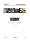
USER MANUAL
DexTempTM 1000 Temperature Monitor (P/N: IR-1001)
DexTempTM 1000
USB Non-Contact Temperature Monitor
User Manual
8690 Rev B
Update: 10/24/2013
1
USER MANUAL
DexTempTM 1000 Temperature Monitor (P/N: IR-1001)
Table of Contents
1
Introduction………………………………………………….……….…… 3
2
Host computer requirements………………………………….…….…….. 4
3
Installing the software…………………………………………..….……... 4
4
DexTempTM 1000 temperature monitor hardware overview……..….…… 5
5
DexTempTM 1000 temperature monitor PC software……………..………
5.1 Overview………………………………………………………….…...
5.2 Running the DexTempTM 1000 temperature monitor software……….
5.3 Main window controls…………………………….…………..……….
5.4 Data point labels and Graph Zooming……….………………..…….…
5.5 Software updates……………………………………………………….
6
DexTemp Information menu………………….……………………..…..… 12
6.1 User Name………………………………….…………………..……... 13
7
Setup: Alarm and Email/Text Server………………………..….……..…...
7.1 Alarm………………………………………………………….…….....
7.2 Setting Alarm: Maximum………...……………………………….…...
7.3 Setting Alarm: Minimum…………………………….………….……..
7.4 Alarm: Enable Audio Alarms……………………………..….………..
7.5 Email / Text Server Setup…………………………………….………..
8
Graph Assignment…………………..…………………………………..... 18
8690 Rev B
Update: 10/24/2013
6
6
6
8
10
12
13
13
14
15
15
16
2
USER MANUAL
DexTempTM 1000 Temperature Monitor (P/N: IR-1001)
1.
Introduction
The DexTempTM 1000 Non-Contact Infrared Temperature Monitor is designed to be a convenient, easy to use product.
Point it at the object to be monitored, click the mouse button, and start monitoring its temperature. When the temperature
reaches a set point, the software will send an email and/or a text message alert. Based on a plug-and-play USB
connection and a standard Windows® PC, the software will install and run by itself.
Features include:
•
•
•
•
•
•
•
•
•
•
•
Factory calibrated temperature output
Easy to use USB format
Measure temperatures without touching the object
Store temperatures in PC log file
Easily view and retrieve data in standard spreadsheets
Over and Under temperature alerts by email and/or SMS text messages
Easy to use graphical interface allows data display and setting of alarm thresholds
Temperature measurements in digital format
Standardized mounting [threaded insert (¼"-20) for tripod]
Small size
Plug and Play
The DexTempTM 1000 kit (P/N: IR-2001) contains the following items:
•
•
•
One DexTempTM 1000 USB non-contact temperature monitor
One USB Cable, 3 feet length (0.9m)
One mini DVD-ROM, containing the PC software and manual
For long term temperature sensing, a ¼"-20 threaded insert is embedded in the temperature monitor. This permits easy
mounting to hold the DexTempTM 1000 in the proper position to monitor the object temperature. Thread the DexTempTM
1000 onto the ¼"-20 mounting screw until it contacts the lock nut. Do not over-tighten or damage may occur.
The DexTempTM 1000 is based on Dexter Research Centers Temperature Sensor Module (TSM), which is a cost
competitive hardware design implemented with low cost development tools and software. The TSM is an excellent
starting point for any hardware design for non-contact Infrared temperature monitoring.
8690 Rev B
Update: 10/24/2013
3
USER MANUAL
DexTempTM 1000 Temperature Monitor (P/N: IR-1001)
2.
Host computer requirements
The DexTempTM 1000 requires the following hardware and software requirements:
Note: A single USB certified cable must be used.
Operating
Windows® XP
Windows® 7
Windows® 8
System → (Service Pack 2 or greater)
(32 or 64 bit)
(32 or 64 bit)
Specs
Minimum Recommended Minimum Recommended Minimum Recommended
CPU
400 MHz
RAM
96 MB
HDD
2 GB
VGA
1024x768
USB Ports
1
DVD-ROM*
yes
Internet**
yes
Audio***
yes
1 GHz
256 MB
3
1 GHz
1 GB
21 GB
1024x768
1
yes
yes
yes
1 GHz
2 GB
3
1 GHz
1 GB
21 GB
1024x768
1
yes
yes
yes
1 GHz
2 GB
3
®
*Mini DVD contains required software, EULA, Microsoft .NET 3.5 sp1, and Graph controls.
**For email and text message alerts, software updates.
***For use with optional audible alarm.
Table 1. Minimum PC system requirements for DexTempTM 1000 temperature monitor
3.
Installing the software
The DexTempTM 1000 temperature monitor is easy to install. Insert the DVD into the computer’s drive. If auto run is
enabled on the system, the software installation should start automatically. Otherwise, go to the start button on the PC,
click on My Computer, right click on DVD and select explore, click on the file named “setup.exe” on the DVD drive to
start the process manually.
Accept each of the Microsoft® software licenses if not already installed on the computer. Windows® 8 does not include
Dot Net 3.5, or Dot Net 3.5 service pack 1. During the installation of Service pack 1 permission will be requested to
download Dot Net 3.5, which will require internet access.
After the software is installed, connect the DexTempTM 1000 temperature monitor to any USB port on the computer.
To use the DexTempTM 1000 temperature monitor, connect the temperature monitor to an open USB port on the host
system. The LED will illuminate a steady RED indicating the DexTempTM 1000 temperature monitor has power.
Note: A single USB certified cable (not to exceed 3 meters) must be used if supplying a cable.
The software will be installed in a separate Dexter Research Center directory and can be accessed at the following path:
C:\Program Files\Dexter Research Center\DexTemp1000. The icon is shown in the Figure below.
Figure 1. Icon for the DexTemp™ 1000 temperature monitor
8690 Rev B
Update: 10/24/2013
4
USER MANUAL
DexTempTM 1000 Temperature Monitor (P/N: IR-1001)
4.
DexTempTM 1000 temperature monitor hardware overview
4
3
2
1
Figure 2.
Figure 2 shows the top view of the DexTempTM 1000 temperature monitor on tripod mount with cable not inserted. The
numbered areas are as follows:
1. Temperature Sensor Module (TSM) with 35° Field of View (FOV) (p/n: MD-0005). This side to be pointed at object
to measure
NOTE: Object to measure must fill the field of view to meet the specifications on the data sheet. The DexTempTM
1000 temperature monitor measures the average temperature of all objects in the FOV spot area. To
accurately measure the temperature of an object, the object must fill the FOV spot area, as shown in
Figure 3.
Figure 3. Field of View and Distance-To-Spot sizes
NOTE: Object temperature measurement accuracy may be affected by certain object material properties. To
improve object temperature measurement accuracy of a metal object (with a low Emissivity), consider
covering the object surface to be measured with masking tape, flat black paint, or spray oil.
For more information about emissivity and non-contact temperature measurement, see the following internet link or
other available resources: http://www.raytek.com/Raytek/en-r0/IREducation/Principlesof+IR.htm
A resource for the Emissivity of common materials can be found at:
http://www.raytek.com/Raytek/en-r0/IREducation/Emissivity.htm
8690 Rev B
Update: 10/24/2013
5
USER MANUAL
DexTempTM 1000 Temperature Monitor (P/N: IR-1001)
2. Standardized mounting [threaded insert (¼"-20) for tripod]
Note: Do not over-tighten, or damage will occur.
3.
USB Micro B receptacle for USB cable connection.
4. USB Micro B connector (Dexter P/N AC-1015).
Note: A single USB certified cable (not to exceed 3 meters) must be used if supplying a cable.
5.
Figure 4. Photograph of Bottom View
5.
Status LED: The LED is continuously illuminated when connected to the PC and not taking data. LED will blink
once per second during temperature sampling. The LED will blink 6 times per second to assist with Individual
Monitor Identification (IMI) as shown in Table 2.
LED Illumination
Status
ON
No data collection
Slow Blinking (1/sec)
Data collection
Fast Blinking (6/sec)
IMI
Table 2. LED Illumination and Status
5.
DexTempTM 1000 temperature monitor PC software
5.1 Overview
The DexTempTM 1000 temperature monitor is a Non-Contact Infrared Temperature Monitor that’s designed to be a
convenient, easy to use product. Point it at the object to monitor, click the start button, and begin monitoring
temperature. Basic object temperature readings of the DexTempTM 1000 temperature monitor can be captured, logged
and displayed on the PC screen. When the temperature has reached a set point, the software can send an email and/or a
text message with an alert.
5.2 Running the DexTempTM1000 temperature monitor software
The software can collect data from up to three DexTempTM 1000 temperature monitors at one time. Insert the first
DexTempTM 1000 temperature monitor into any USB port on the PC. The red LED should be “ON” at this time.
There are three ways to launch the software:
• Click on the shortcut located on the PC desktop (as shown to the right)
• Click on the Start Button, Click on All Programs, Click on Dexter Research Center
folder, Click on the DexTemp1000 folder, Click on DexTemp
• Navigate to My Computer from the Start Button to the following path:
C:\Program Files\Dexter Research Center\DexTemp1000.
8690 Rev B
Update: 10/24/2013
6
USER MANUAL
DexTempTM 1000 Temperature Monitor (P/N: IR-1001)
The Startup screen will appear on the desktop:
Figure 5 Startup screen - single monitor
Figure 6 Startup screen: three graphs shown,
with no monitors connected
The software will automatically recognize the DexTempTM 1000 temperature monitor and open the main screen. The
user-defined name is shown in three areas of the screen highlighted by arrows (Figure 5). See section 6.1 for updating
this field. Placing the mouse over the RED graph will cause the status LED to blink at a faster rate (6 blinks per second)
which can be useful when working with more than one DexTempTM 1000 temperature monitor.
When communication is established, a message showing “1 of 1 DexTemp1000’s attached” will appear in the lower left
corner of the window. If there are no DexTempTM 1000 temperature monitors attached, the screen will show three
graphs and a flashing yellow message at the bottom of the window (Figure 6).
Figure 7.
Figure 8.
Additional graphs and controls will appear as temperature monitors are added. The initial default color assignments are
Red for the first DexTempTM 1000 temperature monitor; Blue for the second; and Green for the third. Those color
assignments can be re-assigned, as shown later in section 8.
To use the IMI (Individual Monitor Identification) feature, placing the mouse pointer over a graph will cause that
particular DexTempTM 1000 temperature monitor’s LED to blink rapidly. The IMI feature is only functional when not
taking data.
These DexTempTM 1000 temperature monitors are now known to the software and saved to disk along with the graph
association. These saved settings will then be used upon re-start.
Note: Connecting or disconnecting a monitor will stop data collection. To restart, click the start button.
8690 Rev B
Update: 10/24/2013
7
USER MANUAL
DexTempTM 1000 Temperature Monitor (P/N: IR-1001)
5.3 Main window controls
Note: Certain control features are not adjustable (grayed out) while software is collecting data. To adjust these
features click the stop button.
Button Icon
Button Description
Exit button: Exits the program.
Start / Stop button: Click Start to begin taking measurements and update graphs.
Start / Stop button: Button will turn to Stop. Click to stop taking measurements.
See Auto Start below for more information.
Note: This button will not appear on the screen if there are no communications with the
DexTempTM 1000 temperature monitor or there is a graph assignment issue (see section 8).
Log Off / Log On button: Clicking Log Off or the LOG menu will allow temperature data to be
stored on the computer (only in °C). Time/Date stamped data will be stored to an Excel® CSV file as
named by the user. Data is always appended to the end of the file and never erased. This button will
change to green with “Log ON” when the data log feature is enabled. Click again to disable logging.
Note: Specify log file name each time “Log” button is clicked.
Print: Clicking Print on the toolbar will call up the printer dialog screen to print the current displayed
graph.
Erase Graph button: Clicking Erase Graph will erase all data from the current displayed graph.
°C °F button: Clicking °C °F selects Celsius or Fahrenheit scale. This will only change the graph
and thermometer display scale.
Note: The Log file always stores temperatures in °C.
Caution: Changing this setting will erase all data on the graph.
Display Length: Display Length allows user to adjust the amount of data displayed on the graph from
5 seconds to 4 weeks. As an example, if 5 seconds is selected then only the most recent 5 seconds of
data is displayed. When selecting lengths greater than 1 hour, the Display and Log file update times
will also change. The maximum number of temperature points that can be displayed is 7200. This
makes the graph response reasonable.
Note: The DexTempTM 1000 temperature monitor records at two samples per second for all
alarm monitoring and digital displays.
8690 Rev B
Update: 10/24/2013
8
USER MANUAL
DexTempTM 1000 Temperature Monitor (P/N: IR-1001)
Zoom out button: Clicking Zoom out will return the display to default state. For more information,
see section 5.4.
Show labels box: The Show labels box will display data labels for each point on all three graphs. This
feature is only enabled with a maximum of 30 data points on the graph. Labels will make the graph
unreadable with more than 30 points of data. This feature is most useful under zoom conditions.
Figure 9.
Note: During data collection this feature is disabled for faster update speed.
Show Graph boxes: Selecting each Show Graph box will display that graph. If the box is not
selected, the graph will not be displayed, but data will continue to be collected and saved.
As a minimum, one graph must be selected. To display a different graph, select a different graph first,
before de-selecting the first graph. This is useful to obtain a larger portion of the graph for a given
DexTempTM 1000 temperature monitor.
The DexTempTM 1000 temperature monitor’s User Name will appear for each of the graph’s check
boxes with its associated color (see section 6.1). Also placing the mouse pointer over each of the
graphs check boxes will cause that particular DexTempTM 1000 temperature monitor’s LED to blink
rapidly. The IMI feature is described in section 5.2.
Auto Start box: In the event of power interruption to the computer, selecting Auto Start allows for
the automatic re-start of the program with previous settings, once power is restored. Data collection
begins 10 minutes after program start-up.
The start button will display AUTO during program re-start when this feature is enabled. Most PCs
have a BIOS setting that can power up the computer automatically when power is restored. A
DexTempTM 1000 temperature monitor shortcut must be placed in the startup folder. If email or text
messaging is enabled, the software will issue an “Autoboot Startup” message. This provides notice that
the computer has re-started and may need attention.
Max and Min limit and digital temperature display: Each graph has “Y” axis maximum and
minimum display settings. This sets the resolution of the graph and thermometer on the screen only; it
has no effect on the DexTempTM 1000 temperature monitor or alarm settings.
Note: Graph maximum display range is 1000°.
Alarm Status: There are four modes of Alarm Status, as shown in Table 3.
The Alarm indicator will show an X if alarms are disabled.
The Alarm indicator will be Green when no Alarms are triggered.
The Alarm indicator will be Yellow when the Alarm Threshold is exceeded and the “Delay Time
Before Alarm” is activated. If the temperature goes back inside set thresholds, the alarm timer is reset
and no alarm will be triggered.
The Alarm indicator will blink Red when the Alarm Threshold and the “Delay Time Before Alarm”
are exceeded.
Note: When the alarm is Red, clicking the alarm indicator will reset the alarm.
8690 Rev B
Update: 10/24/2013
9
USER MANUAL
DexTempTM 1000 Temperature Monitor (P/N: IR-1001)
Status
Alarms disabled
No Alarms triggered
Alarm Threshold exceeded and “Delay Time Before Alarm” activated
Alarm Threshold and “Delay Time Before Alarm” exceeded
Table 3.
Indicator
X
Green
Yellow
Blinking Red
The tool-tip will show current alarm settings when the mouse is placed over the
indicator.
5.4 Data point labels and Graph Zooming
Data Point Labels: Data point labels will show up on a graph
when the mouse pointer is placed over a data point when not
collecting data. Shown in figure 10.
Each label will display its point number, temperature and the
time it was acquired.
As larger amounts of data are collected, a small mouse
movement may be required for the software to determine a data
point. It is easier to place the mouse on a data point when
zoomed in.
Figure 10.
Zooming: There are two methods of zooming in on a graph.
• Click Zooming: Click the mouse on a point of interest
• Drag Zooming: Place the mouse at the starting corner, press and hold the left button dragging the mouse to the
ending corner.
Click Zooming: Click zooming is the easiest and fastest method. Place the mouse anywhere on a graph, left click the
mouse button and all graphs will zoom to the location of the mouse pointer. Data labels are not required to be displayed
to click zoom.
Click zooming has two views. 100 point view and 30 point view, as shown in Figure 11, 12, and 13. The first mouse
click will center the graph with 50 data points to the left and right of the click point. A second mouse click on this new
view will zoom to the 30 point view with 15 data points to the left and right.
Figure 11. Normal view
8690 Rev B
100 point view
30 point view
Figure 12. 100 point view
Figure 13. 30 point view
Update: 10/24/2013
10
USER MANUAL
DexTempTM 1000 Temperature Monitor (P/N: IR-1001)
At the 30 point zoom view, Show Labels feature can be enabled, as
shown in Figure 14. Labels will be printed when using the Print
function.
The Drag Zooming method allows zooming in for more detail. The X
and Y axis scroll bars can also be used to explore other parts of the data
set.
Figure 14. Data labels
Drag Zooming:
Use the mouse to highlight a section of graph. Place the mouse at the starting corner, press and hold the left button while
dragging the mouse to the ending corner, Figure 16.
Releasing the mouse button will update all graphs as selected, Figure 17.
Figure 15. Normal view
Figure 16. Highlighted view
Axis zoom out buttons
Figure 17. Zoomed view
Each graph will now have a set of scroll bars and zoom out buttons. See Figure 18. The Axis Zoom Out button for each
axis will zoom out one view for that axis.
Figure 18. X-Axis Zoom Out button
8690 Rev B
Update: 10/24/2013
11
USER MANUAL
DexTempTM 1000 Temperature Monitor (P/N: IR-1001)
Multiple zoom views are possible. Repetitive zooming allows for more detail.
Figure 19. Selected zoom area
Figure 20. Zoomed area
To get back to the Normal View, click on the Axis Zoom Out button or click on the global Zoom Out button.
Note: Clicking “Erase Graph” or “Start” will go back to the “NO” zoom state.
5.5 Software updates
The DexTempTM 1000 temperature monitor’s PC software will automatically check for update every 30 days using the
internet. The user can also check for software updates manually by selecting “Help” and “Check for updates” or
“Updates are available” in the drop down menu. Update status will appear in the lower right corner of the screen.
6.
DexTemp Information menu
Each DexTempTM 1000 temperature monitor has the
ability to store information inside the monitor. Most of
this information is factory programmed. The information
that can be changed is limited to the User Name, as
described in section 6.1.
Each DexTempTM 1000 temperature monitor (maximum
of 3 monitors) that is attached will be presented on its
own tab, Figure 21. Each tab label will have the current
“User Name”. Each DexTempTM 1000 temperature
monitor’s tab will also be displayed in the color of the
graph it is assigned to. When a DexTempTM 1000
temperature monitor’s tab is displayed in black, it is not
assigned to a graph.
Note: This screen is disabled while collecting data.
Figure 21.
Note: When a DexTempTM 1000 temperature monitor’s tab is selected, it’s LED will blink rapidly.
8690 Rev B
Update: 10/24/2013
12
USER MANUAL
DexTempTM 1000 Temperature Monitor (P/N: IR-1001)
6.1 User Name
Each DexTempTM 1000 temperature monitor has the Sensor S/N (Serial
Number) pre-assigned into the User Name field. The S/N can be replaced
with a more intuitive User Name. The User Name will be used for graph
labels, log files, alarms, emails and text messages.
As an example, in Figure 22, the User Name of “C88C440C2799B000” is
changed to “Hot Water Heater”.
Note: The User Name is limited to 16 characters.
Figure 22.
7.
Setup: Alarm and Email/Text Server
The Setup tab is used to access the Alarm and Email/Text
Server options.
Note: This screen is disabled while collecting data.
Figure 23.
7.1
Alarms
Enable Alarms: When checked, turns on alarm functions for a specific
DexTempTM 1000 temperature monitor. Each DexTempTM 1000 temperature
monitor has high and low temperature alarm limits. An alarm will be triggered
when limits are exceeded. The alarm can be a visual alarm, audio alarm, email,
and/or SMS text message.
Each DexTempTM 1000 temperature monitor that is assigned to a graph will be
presented on its own tab. It’s tab label will display the User Name. Each tab’s
text color will be the same color as the assigned graph. Unassigned DexTempTM
1000 temperature monitor’s will not be displayed.
Each tab has four settings: Maximum threshold, Minimum threshold, Enable
Alarms, and Place reading at beginning of message.
Figure 24.
Note: The temperature units follow the main screen settings using the °C -°F button.
When a DexTempTM 1000 temperature monitor’s tab is selected, it’s LED will blink rapidly.
8690 Rev B
Update: 10/24/2013
13
USER MANUAL
DexTempTM 1000 Temperature Monitor (P/N: IR-1001)
7.2
Setting Alarm: Maximum
Figure 25.
ALARM THRESHOLD MAXIMUM: Figure 25 shows the entry box for the object temperature that will trigger an
alarm. Alarm will not trigger until Delay Time is exceeded.
This entry field has the following limits:
• The highest value is 380°C (716°F). This is the upper limit of the DexTempTM 1000 temperature monitor.
• The lowest value is based on two other settings, the Reset Threshold (if enabled) or the ALARM THRESHOLD
MINIMUM, which ever is higher.
DELAY TIME BEFORE ALARM/RESET: Figure 25 shows the entry box for the time that the object temperature is
equal to or above the Alarm Threshold before alarm is triggered. The alarm will not be triggered if the temperature drops
below the threshold before the delay time is met. Adjust the delay time to avoid unwanted alarms caused by temperature
spikes. Delay time minimum is 1 second.
Alarm Reset: The Alarm Reset allows the alarm to be automatically reset after trigger. The object temperature must
meet or drop below, before reset of the alarm occurs. When the “Alarm Reset” is checked, Figure 24, both maximum and
minimum reset temperatures will be enabled.
Alarm status icon
When the Alarm Reset is un-checked, the alarm must be manually cleared either by
stopping the data collection or by clicking on the alarm status icon on the main screen.
Note: The DELAY TIME BEFORE ALARM/RESET is also used for the Alarm
Reset.
Figure 26.
Alarm Message: Figure 25 shows the entry box for text messages sent by email or SMS (74 character limit). The word
“Reset” will be added to the beginning of a message when the Alarm Reset is activated.
Note: The Subject of the message will contain the User Name and Max. Alarm.
The Alarm Message may be customized with additional information such as monitor location, contact phone number, or
action to take.
When Alarms are enabled the graph will show light red and light blue
strips at minimum and maximum alarm levels. Giving a clear indication
where the measured temperature is relative to the Alarm limits.
Figure 27.
8690 Rev B
Update: 10/24/2013
14
USER MANUAL
DexTempTM 1000 Temperature Monitor (P/N: IR-1001)
7.3
Setting Alarm: Minimum
Figure 28.
ALARM THRESHOLD MINIMUM: Figure 28 shows the entry box for the object temperature that will trigger an
alarm. Alarm will not trigger until Delay Time is exceeded.
This entry field has the following limits:
• The lowest value is -40°C (-40°F). This is the lower limit of the DexTempTM 1000 temperature monitor.
• The highest value is based on two other settings, the Reset Threshold (if enabled) or the ALARM
THRESHOLD MINIMUM, which ever is lower.
DELAY TIME BEFORE ALARM/RESET: Figure 28 shows the entry box for the time that the object temperature is
equal to or below the Alarm Threshold before alarm is triggered. The alarm will not be triggered if the temperature rises
above the threshold before the delay time is met. Adjust the delay time to avoid unwanted alarms caused by temperature
spikes. Delay time minimum is 1 second.
Alarm Reset: The Alarm Reset allows the alarm to be automatically reset after trigger. The object temperature must
meet or rise above, before reset of the alarm occurs. When the “Alarm Reset” is checked, Figure 24, both maximum and
minimum reset temperatures will be enabled.
Alarm status icon
When the Alarm Reset is un-checked, the alarm must be manually cleared either by
stopping the data collection or by clicking on the alarm status icon on the main screen.
Note: The DELAY TIME BEFORE ALARM/RESET is also used for the Alarm
Reset.
Figure 29.
Alarm Message: Figure 28 shows the entry box for text messages sent by email or SMS (74 character limit). The word
“Reset” will be added to the beginning of a message when the Alarm Reset is activated.
Note: The Subject of the message will contain the User Name and Min. Alarm.
The Alarm Message may be customized with additional information such as monitor location, contact phone number, or
action to take.
7.4
Alarm: Enable Audio Alarms
Enable Audio Alarms: When enabled, produces a sound when any of the
DexTempTM 1000 temperature monitor’s alarms are triggered. This applies to all
connected DexTempTM 1000 temperature monitors.
8690 Rev B
Update: 10/24/2013
Figure 30.
15
USER MANUAL
DexTempTM 1000 Temperature Monitor (P/N: IR-1001)
7.5
Email/SMS Text Server Setup
There are several options that should be selected when first setting up alerts. Figure 31 outlines the set-up process.
• How should alerts be sent (either email and/or SMS text messages)?
• How many alerts to receive at maximum (such as 100 per hour versus 1 per day), etc.
2
1
3
5
4
7
6
11
8
10
9
Figure 31. Email/Text Server Setup steps outlined in Examples 1 and 2.
Below, two examples show typical set-up for internet email accounts.
Example 1 uses a Google Gmail1 account and a Verizon2 SMS (Short Message Service) text account. JohnDoe would
also like to send alerts from his Internet Service Provider (ISP) account to his wife, JaneDoe. He has entered her internet
email account information and her cell phone SMS text information into the proper locations. However he would like to
limit the maximum number of alerts received by Jane to 3 alerts per day.
Example 2 uses a Microsoft® Outlook.com account (aka hotmail3) and two cell phones: AT&T4 and Sprint5 SMS text
account. They would like to receive alerts on both their email accounts and their cell phones SMS text account, so they
have enabled the email alert check box. Charlie and his brother JeffDoe would like to have their account named
MyWaterHeater, and limit on the number of alerts that is sent at 12 per hour (Example 2).
1
2
3
4
5
6
7
8
Action
Enter SMTP information
Enter Port number
Enable secure connection
Enter Account Name
Enter Password
Enter Sent From name
Enable Email alerts
Enter Send To name
Example 1
smtp.gmail.com
587
enabled
[email protected]
•••
[email protected]
enabled
[email protected]
Example 2
smtp.live.com
587
enabled
[email protected]
••••••
[email protected]
enabled
CharlieDoe,JeffDoe,[email protected],
[email protected]
9
Optional: (Automatically select phone [email protected]
SMS format using Phone SMS table)
10 Select Max. messages received
3 per day
12 per hour
11 Click Message Test to send test Alert
12 Click OK to save settings and exit to
main screen.
8690 Rev B
Update: 10/24/2013
16
USER MANUAL
DexTempTM 1000 Temperature Monitor (P/N: IR-1001)
Helpful suggestions:
a) Alerts may be received by: email, SMS text, or both.
b) The host computer (PC) must have access to the internet at all times for these features.
c) SMTP (Simple Mail Transfer Protocol) is required as the Alert server. Many popular internet email services offer
SMTP as a low or no-cost service.
Note: Some private or corporate email services may restrict access. It is recommended to use internet email
services.
d) Some internet email accounts use out-going mail port number 587. Check with the ISP to confirm.
e) Most internet email accounts require the use of a secure connection. Figure 31 #3.
f) Most internet email accounts require the same Account Name as the login name.
Note: Do not enter a unique name in the ”Sent From”. Figure 31 #4 and #6.
g) Many SMS text providers require login to phone SMS account before sending a text message. Figure 31 #9.
h) Some SMS text providers require a recipients’ number to use a leading “1”. Some European providers (Such as O2
in the UK) require the recipients’ number to use a leading “44”. Check with SMS text provider to confirm.
i) Some internet email providers allow user-friendly names such as MyWaterHeater. Shown in Example 2, line 6.
j) Email alerts are enabled by checking the box. Figure 31 #7.
k) When entering SMS text account, do not use hyphens. For instance: use 1234567890, not 123-456-7890
l) If a SMS text account is selected from the Phone SMS table, all other entries in ”Send To” will be erased. Use exact
SMS text recipient number to replace the word “number” that automatically is populated. Figure 31 #9.
Note: The Phone SMS table may NOT contain all SMS text providers.
m) Send an Alert Test to the recipient before leaving this screen. This will ensure that the settings have been entered
properly and are working.
n) When using multiple recipients to receive alerts, they must be separated by just one comma, no spaces. Such as:
“CharlieDoe,JeffDoe,[email protected],[email protected]”
o) A helpful summary of Alerts is shown in the lower right hand portion of the main screen, shown in Figure 32.
p) The message counter is reset when starting or stopping data collection.
Summary of Alerts, maximum limit, and Alerts not sent
Figure 32.
1
2
3
4
5
Gmail (www.gmail.com) is a registered trademark and product of Google®.
Verizon (www.vtext.com) is a registered trademark and product of Verizon®.
®
Outlook and Hotmail (www.outlook.com) are a registered trademark and product of Microsoft .
AT&T (www.txt.att.net) is a registered trademark and product of AT&T®.
Sprint (www.sprint.com) is a registered trademark and product of Sprint®.
8690 Rev B
Update: 10/24/2013
17
USER MANUAL
DexTempTM 1000 Temperature Monitor (P/N: IR-1001)
8.
Graph Assignment
Figure 33.
Figure 34.
Figure 35.
Note: The Graph Assignment screen is disabled while collecting data.
Each DexTempTM 1000 temperature monitor is automatically assigned to the Red, Blue and Green graphs in this order,
Figure 33 and 34. These monitor’s are saved to disk along with the graph associations. All settings (alarms, messaging,
graph max & min) will also be saved to disk, enabling the software to remember the latest configuration.
Placing the mouse pointer over a User Name will cause that particular DexTempTM 1000 temperature monitor’s LED to
blink rapidly.
The Graph Assignment screen shows a matrix of DexTempTM 1000 temperature monitor User Name’s, USB connection
Status, and assignment buttons, for each of the Red, Blue and Green graphs. The assignment buttons will be green to
indicate which color graph a DexTempTM 1000 temperature monitor is assigned. The remaining buttons in the
corresponding row and column will be grayed out (unavailable).
The USB Connection Status has three possible levels, Figure 36:
YES
The DexTempTM 1000 temperature monitor is connected to a USB port,
NO
The DexTempTM 1000 temperature monitor is not connected to a USB port
NEW
The DexTempTM 1000 temperature monitor is connected to a USB port but is not currently assigned to
a graph.
Figure 36.
Figure 37.
Clicking the "Clear" button for a monitor will remove the graph assignment and the User Name will change its color to
black, Figure 36. The monitor and graph are now available for reassignment.
Click on the available buttons to reassign each DexTempTM 1000 temperature monitor to a new graph. User Name color
will change to match the new graph’s color, Figure 37.
8690 Rev B
Update: 10/24/2013
18
USER MANUAL
DexTempTM 1000 Temperature Monitor (P/N: IR-1001)
The main screen will now be updated with the new graph
assignment and the monitor’s associated settings.
Figure 38.
The software will allow up to 3 assigned and 3 unassigned monitors to be displayed on the Graph Assignment window.
Note: The software will not recognize more than 3 monitors connected at any one time.
Figure 39a.
Figure 39b.
Note: The main screen bottom banner will blink yellow when an unassigned monitor is connected (Figure 39a).
Data collection will be disabled until graph assignment is resolved, and start button is clicked.
Figure 40a.
8690 Rev B
Figure 40b.
Update: 10/24/2013
19
USER MANUAL
DexTempTM 1000 Temperature Monitor (P/N: IR-1001)
A maximum of three monitors can be assigned at any given time.
When a new monitor is desired:
• Disconnect one of the assigned monitors (User name will turn gray, Figure 39b)
• Connect the new monitor (monitor will appear as unassigned, Figure 39b)
• Click the clear button to un-assign the disconnected monitor (which has been grayed out, Figure 40a)
• Assign the new monitor to the unassigned graph (Figure 40b)
Figure 41.
The new graph assignment will be applied to the main screen, Figure 41. All previous settings (alarms, messaging, graph
max & min) will transfer to the new monitor.
Note: This product complies with part 15 (Unintentional Radiator and Emission) of the FCC rules and European
standard EN 55022:2010 and EN 55024:2010. Declaration of Conformity is on file.
If you are experiencing any problems with the DexTempTM 1000 or require additional support, please contact
customer service at Dexter Research Center, Inc. at (734) 426-3921
© 2013 Dexter Research Center, Inc. All rights reserved.
For the latest version of this Manual (P/N: AC-1013) and software, go to our web site:
www.DexterResearch.com/DexTemp1000
For additional information, contact Dexter Research Center:
Dexter Research Center, Inc.
7300 Huron River Drive
Dexter, MI 48130 U.S.A.
Phone: +1 734-426-3921
Fax: +1 734-426-5090
8690 Rev B
Update: 10/24/2013
20