1
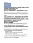
Fido X3
OPERATIONS
MANUAL
COPYRIGHT
©2014 FLIR Systems, Inc.
September 2014 REV 2c
This documentation is provided as a component of the Fido
detection system. All parties or individuals in possession of
this documentation accept in full and without exception or
limitation FLIR Systems, Inc. unrestricted rights of ownership of
this material. This documentation is not available by any other
means except by license which is only available from FLIR
Systems, Inc. Under no circumstances may any part or the
whole of this documentation be reproduced, stored in a retrieval
system, transmitted, copied, modified, distributed, displayed,
sold, licensed, published or derivative works created therefrom
in any form or by any means: electronic, mechanical, recording,
or otherwise, without the written permission of FLIR Systems,
Inc. obtained in advance of the requirement.
It is expressly forbidden for the holder of this documentation to
use it either in its entirety or in part or any graphics to provide
training or tuition, assistance or knowledge transfer to any other
party whatsoever, or for marketing of promotional literature
or material of any type whatsoever without the prior written
permission of FLIR Systems, Inc. Use of this documentation
in any manner inconsistent with the user manual and related
documentation is strictly prohibited. Use of the documentation
is not transferable.
TRADEMARKS
Product name and any design elements are registered
trademarks of FLIR Systems, Inc. All other product and company
names may be the property of their respective owners.
PROPRIETARY INFORMATION
This documentation contains confidential and proprietary
information that must be maintained in confidence, used only in
a manner consistent with the documentation, and may not be
disclosed to any third parties.
WARRANTY STATEMENT
The Fido equipment that is the subject of this manual is covered
by a standard warranty. The terms of the warranty are defined by
the “Terms and Conditions of Sale” that was in effect at the time
of purchase. A copy of this document can be obtained through
your FLIR Systems sales channel for Detection Products.
FLIR Systems, Inc.
Explosives Detection
1024 South Innovation Way
Stillwater, Oklahoma 74074
USA
T + 1.405.372.9535
F + 1.405.372.9537
www.flir.com/detection
TABLE OF CONTENTS
1.0
1.1
1.2
1.3
2.0
3.0
3.1
3.2
3.3
3.3.1
3.3.2
3.3.3
SAFETY SUMMARY........................................................1
POWER CABLES..............................................................1
DESORBER AND INLET TIP........................................2
SENSING ELEMENT.......................................................2
THEORY OF OPERATION.............................................3
SYSTEM OVERVIEW.......................................................7
MILITARY KIT COMPONENTS....................................8
COMMERCIAL KIT COMPONENTS.......................10
EXTERIOR OVERVIEW................................................13
FRONT OF UNIT...................................................................13
SOFT KEYS, BUTTONS, AND DISPLAY TABS...................13
BACK OF UNIT.....................................................................14
3.4 DISPLAY ICONS AND COMPONENTS..................15
3.4.1 STATUS ICON.......................................................................16
3.4.2 BATTERY ICON....................................................................17
3.4.3 EXTERNAL POWER CONNECTION ICON.........................18
3.4.4 WIFI ICON.............................................................................18
4.0 GET STARTED OPERATING GUIDE........................21
4.1 POWER UP AND LOGIN..............................................21
4.2 INSTALL NEW SENSING ELEMENT.......................23
4.2.1 WHEN TO REPLACE SENSING ELEMENT........................24
4.2.2 TO REMOVE SENSING ELEMENT......................................24
4.2.3 TO INSTALL SENSING ELEMENT .....................................28
4.3 SCAN RFID TAG ON SENSING ELEMENT BAG.35
4.4 LOG OUT OR POWER OFF........................................38
4.4.1 ENABLE THE LOG OUT, CANCEL OR OFF TABS.............38
4.4.2CANCEL................................................................................38
4.4.3 LOG OUT..............................................................................38
TABLE OF CONTENTS
4.4.4
POWER OFF.........................................................................39
5.0 VERIFY SENSOR PERFORMANCE (DESORBER
ATTACHED)...................................................................................41
5.1 TO VERIFY........................................................................41
5.1.1
VERIFY OUTCOME..............................................................47
TO VERIFY DURING OPERATION...........................49
5.2.1 TO VERIFY AT WILL.............................................................50
5.3 TROUBLESHOOT VERIFY FAILED..........................52
6.0 PARTICLE SAMPLING.................................................53
6.1 SWIPE MATERIALS.......................................................53
6.2 SWIPING BY HAND.......................................................55
6.2.1 TO PREPARE SWIPE...........................................................55
6.2.2 TO SWIPE SURFACES BY HAND.......................................57
6.2.3 TO PRESENT SWIPES TO DESORBER BY HAND............61
6.3RESULTS...........................................................................65
7.0 SWIPING WITH WAND.................................................70
7.1 LOADING WAND............................................................70
7.2 SWIPING WITH WAND.................................................74
7.3 DESORBING USING WAND.......................................78
8.0 COLLECTING VAPOR SAMPLES.............................83
8.1 REMOVING THE DESORBER....................................83
8.2 INSTALLING THE VAPOR GUARD..........................85
8.3 SAMPLING VAPOR........................................................87
8.4RESULTS...........................................................................90
9.0 TABS IN OPERATOR.....................................................93
9.1 PRIMARY TABS OVERVIEW......................................93
5.2
TABLE OF CONTENTS
9.1.1
TO OPEN A PRIMARY TAB.................................................94
9.2 VERIFY TAB......................................................................94
9.3 NEW FILE TAB.................................................................95
9.4 HELP TAB..........................................................................96
9.5 SETUP TAB.......................................................................97
9.5.1 TO SELECT A MENU ITEM IN SETUP TAB........................97
9.5.2 VIBRATE SIGNAL.................................................................99
9.5.3 AUDIO VOLUME..................................................................99
9.5.4BACKLIGHT........................................................................100
9.5.5CONTRAST.........................................................................100
9.5.6FLASHLIGHT......................................................................100
9.6 MUTE/UNMUTE TAB..................................................102
9.6.1 TO MUTE AUDIO TONES..................................................102
9.6.2 TO UNMUTE AUDIO TONES.............................................102
9.7 CLEAN TIP TAB............................................................103
10.0 INLET TIP (WITHOUT DESORBER).......................105
10.1 PREPARE AND PRESENT REFERENCE.............105
10.2 VERIFY OUTCOME......................................................110
10.3 TROUBLESHOOT VERIFY FAILED........................113
11.0 EXTENDED OPERATION...........................................115
11.1 TO CONNECT TO AC POWER................................115
11.1.1INTRODUCTION.................................................................115
11.1.2 TO CONNECT TO AC POWER..........................................115
11.2 TO DISCONNECT FROM AC POWER..................119
11.3 DC POWER.....................................................................120
11.3.1 RECHARGING OPTIONS...................................................121
11.3.2 TIME TO CHARGE.............................................................121
TABLE OF CONTENTS
11.3.3CAPACITY...........................................................................121
11.3.4 AC POWER REQUIRED FOR RECHARGING...................121
11.3.5 TO CHARGE MULTIPLE BATTERIES................................122
11.4 TO CHARGE BATTERY ATTACHED TO UNIT...122
11.5 TO CHARGE BATTERY WITH EXTERNAL
CHARGER....................................................................................123
11.6 TO RECONNECT BATTERY TO UNIT..................129
11.7 SLEEP MODE................................................................131
11.7.1 ABOUT SLEEP MODE.......................................................131
11.7.2 WAKE FROM SLEEP MODE.............................................132
12.0 ERROR MESSAGES....................................................135
12.1 CRITICAL ERROR MESSAGES..............................135
12.2 SENSOR DISABLED MESSAGES..........................136
12.3 PLEASE WAIT MESSAGE.........................................137
12.4 ADDITIONAL (MISCELLANEOUS) MESSAGES.138
13.0 TIPS AND REMINDERS.............................................140
13.1SAFETY............................................................................140
13.2PROCEDURES..............................................................140
13.3CLEANING......................................................................141
13.4OTHER.............................................................................141
14.0SPECIFICATIONS.........................................................143
14.1POWER............................................................................143
14.2TECHNOLOGY..............................................................144
14.3 OPERATING ENVIRONMENT..................................144
14.4 STORAGE ENVIRONMENT......................................144
14.5CONNECTIONS............................................................144
14.6 HOST COMPUTER REQUIREMENTS..................145
TABLE OF CONTENTS
14.7 SUPPORTED OPERATING SYSTEMS..................145
14.8COMMUNICATIONS...................................................145
14.9CAPACITY.......................................................................145
1.0
SAFETY SUMMARY
Follow basic safety precautions and mind the warnings in this
section when operating Fido X3. Failure to do so can result in
serious injury. In addition, the X3 may not operate as intended.
WARNING! ANY EQUIPMENT
CONNECTED THROUGH THE
FIDO X3 DATA PORTS MUST BE
ISOLATED FROM MAINS VOLTAGE
BY THE ISOLATION EQUIVALENT TO
THE REQUIREMENTS OF IEC 61010
OR IEC 60950.
ELECTROCUTION HAZARD!
1.1
POWER CABLES
Check power cables and immediately replace any that appear
crimped or have damaged insulation. Power cables in poor
condition can cause electric shock. Do not submerge Fido X3 in
•
liquid.
Adhesive electrical tape is not a safe or permanent repair for
worn or damaged cables.
Safety
Copyright © 2014 FLIR Systems, Inc.
1
BURN HAZARD!
1.2
DESORBER AND INLET TIP
When the unit is powered, the inlet tip and desorber plate are
hot enough to cause burns. The inlet tip also remains hot for
several minutes after powering the unit off.
BROKEN GLASS HAZARD!
1.3
SENSING ELEMENT
The glass Sensing Element can break if mishandled while being
removed or replaced. If the Sensing Element breaks in the
Sensing Element chamber, tilt the X3 unit over a disposal bin so
any remaining pieces of glass fall out of the chamber and into
the bin.
2
Safety
Copyright © 2014 FLIR Systems, Inc.
2.0
THEORY OF OPERATION
1. Sampling swipes are used to collect particles from a
surface.
•
Sampling swipe
Particles can be collected by hand or with the sampling
wand.
Swiping by hand
Swiping by wand
Theory
Copyright © 2014 FLIR Systems, Inc.
3
•
The area of the swipe against the surface collects the
particles.
•
Pressure exerted by the tip of your finger (or wand) on
the surface forces particles to adhere to the swipe.
Particles (illustrated in red, not actually visible) adhere to swipe
2. The area of the swipe with the collected particles will face
the display screen when presented to the unit.
Particles (illustrated in red, not actually visible) face display. Blue arrows
(again, for illustration only) show direction of insertion.
4
Theory
Copyright © 2014 FLIR Systems, Inc.
3. Particles on the swipe are vaporized in the desorber, drawn
through the heated inlet tip and into the Sensing Element.
Heated inlet tip
4. The sensor analyzes the vaporized particle sample.
Sensor (Sensing Element)
Theory
Copyright © 2014 FLIR Systems, Inc.
5
5. Results of analysis appear in the display screen as Sample
Clear or [THREAT MATERIAL] Alert. The type of explosive
compound that caused the Alert is also given. Some
examples are: Military, Nitro, Peroxide, or Nitrate Alert.
NOTE: The type of compounds that are detected depends upon
the type of Sensing Element that is installed. The Fido X3 is
capable of detecting a variety of analytes. To adjust the current
detection capability with additional Sensing Elements, contact
Fido Sales by phone at 1-405-372-9535.
To start screening samples, skip ahead to Section 4.0.
•
6
Theory
Copyright © 2014 FLIR Systems, Inc.
3.0
SYSTEM OVERVIEW
The Fido X3 comes in two kit configurations; Military and
Commercial. The contents of these kits are mostly the same
with a few key differences:
Exclusive to Military Kits
Exclusive to Commercial Kits
•
MOLLE/Belt Attachment
•
Single-point Harness
•
Printed Manuals
•
CD-ROM with PDF
•
Waterproof Day Bag
Manuals
•
Vapor Guard
•
Sampling Wand
This manual covers the components in both kit variations.
Overview
Copyright © 2014 FLIR Systems, Inc.
7
3.1
MILITARY KIT COMPONENTS
1. MOLLE/Belt Attachment
8. M.E. Reference Standard
2. Waterproof Day Bag
9. USB Cord
3. Printed Manuals
10. AC Power Adapter and
4. Maintenance Kit
5. Spare Battery
AC Power Cord
11. Vapor Reference
6. Sampling Swipes
Standard (2)
(Four boxes/50 swipes
12. Spare Inlet Tip
per box)
13. Battery Charger
7. Sensing Elements
(Two boxes/10 Sensing
Elements per box)
14. Fido X3 with Desorber
and Battery
15. Storage Case
NOTE: Many components in this kit are designed to be
compatible with Fido systems for the purpose of detection
capability upgrades. Thus the appearance of some accessories
(i.e., Body color, Sampling Swipe color or Reference Standard
style) in your kit may differ from the ones shown here and
elsewhere in this manual.
8
Overview
Copyright © 2014 FLIR Systems, Inc.
Fido X3 Military Kit Configuration (in storage case)
Overview
Copyright © 2014 FLIR Systems, Inc.
9
3.2
COMMERCIAL KIT COMPONENTS
1. Storage Case
8. Vapor Guard
2. Sensing Elements
9. AC Power Adapter and
(Two boxes/10 Sensing
Elements per box)
3. Sampling Swipes
AC Power Cord
10. Spare Battery
11. Battery Charger
(Four boxes/50 swipes
12. Single-point Harness
per box)
13. Sampling Wand
4. Spare Inlet Tip
14. M.E. Reference Standard
5. Vapor Reference
15. USB Cord
Standard (2)
16. CD-ROM with PDF
6. Maintenance Kit
7. Fido X3 with Desorber
and Battery
10
Overview
Copyright © 2014 FLIR Systems, Inc.
Manuals (Not Shown)
Fido X3 Commercial Kit contents (removed from storage case)
NOTE: Many components in this kit are designed to be
compatible with Fido systems for the purpose of detection
capability upgrades. Thus the appearance of some accessories
(i.e., Body color, Sampling Swipe color or Reference Standard
style) in your kit may differ from the ones shown here and
elsewhere in this manua.
Overview
Copyright © 2014 FLIR Systems, Inc.
11
To inquire about upgrades, contact Fido Support by
phone at
1-405-372-9535 or email
[email protected].
12
Overview
Copyright © 2014 FLIR Systems, Inc.
3.3
EXTERIOR OVERVIEW
3.3.1
FRONT OF UNIT
1. Desorber
2. Desorber Slot
3. Display Screen
4. Menu (Power)
Button
5. Release Button for
Battery
6. Battery
3.3.2
SOFT KEYS, BUTTONS, AND DISPLAY TABS
A soft key is any one of the three buttons on the unit
immediately under the display. Soft keys have context-specific
functions and each soft key corresponds to a tab in the display
screen with text indicating the soft key’s current function.
Pressing a soft key activates the function shown on the
corresponding tab.
Overview
Copyright © 2014 FLIR Systems, Inc.
13
1. Soft Key for Left Display
Tab (Mute tab in figure)
2. Soft Key for Middle
Display Tab (New File
tab in figure)
3. Soft Key for Right
Display Tab (Verify tab in
figure)
When there are more than three functions possible, a short
press of the Menu button will cycle the functions of the soft
keys (and the text on the tabs accordingly). Toggle the Menu
button until the desired soft key function is shown.
3.3.3
BACK OF UNIT
1. Latch to Sensing
Element Chamber
2. Auxiliary Port
(Cap removed)
3. Flashlight Button
14
Overview
Copyright © 2014 FLIR Systems, Inc.
3.4
DISPLAY ICONS AND COMPONENTS
Primary Operators Screen Components
1. Status Icon
2. Current File Number
6. External Power
Connection Icon
3. Date and Time
7. WiFi Icon
4. Cycling Messages:
8. Display Messages
Unit: Serial Number
9. Tab (for left soft key)
SE: T
Type in Use
10.Tab (for middle soft
5. Battery Icon
key)
11.Tab (for right soft key)
Overview
Copyright © 2014 FLIR Systems, Inc.
15
3.4.1
STATUS ICON
Icon
16
Icon Title
Indication
Gears
System operating within
normal limits
Waiting
Wait while system readies
(i.e., gathers baseline or
stabilizes system).
Alert
Threat material detected.
Error
System error has occurred,
follow the on-screen
instructions and/or refer to
the Error Message tables
in the Appendix.
Overview
Copyright © 2014 FLIR Systems, Inc.
3.4.2
BATTERY ICON
When the unit is operating on battery power, the Battery icon
appears in the Operations screen.
•
Battery icon indicating 20% charge
See Section 11.4 for recharging steps.
The Battery icon also shows the battery charge level by portion
filled with color:
100%
•
80%
60%
40%
20%
Near 0%
An animated icon of the battery filling indicates the
•
battery is charging.
A fully-charged battery provides up to 8 hours of
power to the unit.
Overview
Copyright © 2014 FLIR Systems, Inc.
17
•
It takes approximately 4 hours to fully charge a
depleted battery whether recharged via:
1. The external charger.
2. The unit with under AC power.
3.4.3
EXTERNAL POWER CONNECTION ICON
While the unit is connected to external power, an External
Power Connection icon will be displayed below the battery icon.
3.4.4
WiFi ICON
If WiFi is enabled, a WiFi icon will appear below the External
Power Connection icon area. If WiFi is connected, one of the
following icons will appear to indicate signal strength:
Wireless Access Point Signal Strength
Indicator
Strong
Weak
.
18
Overview
Copyright © 2014 FLIR Systems, Inc.
While attempting to connect, or if there is a problem with the
WiFi connection one of these icons will appear:
Attempting to connect.
Unable to connect, possible configuration or
hardware error.
Overview
Copyright © 2014 FLIR Systems, Inc.
19
This page intentionally left blank.
20
Overview
Copyright © 2014 FLIR Systems, Inc.
4.0
GET STARTED OPERATING GUIDE
To immediately begin operations, start below with Step 1.
4.1
POWER UP AND LOGIN
Step 1:
Press and hold the Menu (Power) button until the
unit powers on.
•
Power button
The FLIR Fido splash screen appears, followed by the
Login screen.
Startup
Copyright © 2014 FLIR Systems, Inc.
21
NOTE: If the unit does not power on after five
seconds, the battery may need charging:
•
Replace the depleted battery with a charged
back-up battery (see Section 11.5).
OR
•
Operate the unit on an external power
adapter (see Section 11.1).
Step 2:
Press the Menu button to enter Basic Operator
mode.
Menu button
NOTE: To enter Administrator mode, see the
Administrator manual.
22
Startup
Copyright © 2014 FLIR Systems, Inc.
To obtain Administrator training,
contact Fido Training by phone at
1-405-372-9535 or email at
[email protected].
Step 3:
Allow a few minutes for the system to reach
operating conditions.
Step 4:
If Replace Sensing Element appears in the display,
go to the next section. If not, skip to Section 5.0.
•
The next part of the process is to install a Sensing
Element.
4.2
INSTALL NEW SENSING ELEMENT
Sensing Elements are available in multiple types: Please see the
information provided on the box.
Startup
Copyright © 2014 FLIR Systems, Inc.
23
Handle the end with dot
Caution! Only handle the end of the Sensing Element with the
colored dot.
4.2.1
WHEN TO REPLACE SENSING ELEMENT
Change Sensing Elements:
1. If troubleshooting a “Verify Failed”.
2. After performing a Power Clean.
3. If the System requests it.
4. When you need a different detection capability.
5. When your operating plan calls for it.
4.2.2
Step 1:
TO REMOVE SENSING ELEMENT
Ensure the unit is powered on. If the desorber is
removed, avoid contact with the inlet tip.
IMPORTANT! The unit must be POWERED ON when seating a
Sensing Element in order to reset the Sensing Element timer.
24
Startup
Copyright © 2014 FLIR Systems, Inc.
The Sensing Element timer records the number of hours that
have elapsed since a Sensing Element was installed.
Step 2:
Position the unit so the back is facing up and the
desorber is farthest away from you.
Turn the Fido over
Startup
Copyright © 2014 FLIR Systems, Inc.
25
Step 3:
Open the Sensing Element door latch.
Flip open latch with fingertips
26
Startup
Copyright © 2014 FLIR Systems, Inc.
Step 4:
Prop the door on the back of the unit.
•
Prop latch on unit
The end of the Sensing Element with the colored dot
extends from the chamber and is warm. The other end of the
Sensing Element is near the inlet tip and hot.
Sensing Element extends from chamber
Startup
Copyright © 2014 FLIR Systems, Inc.
27
WARNING! THE SENSING ELEMENT IS
HOT!
Step 5:
Prepare to catch the Sensing Element in a glass
suitable receptacle (or, if wearing protective gloves,
the palm of your hand).
Step 6:
Tilt the unit up so the Sensing Element slides down
and out of the chamber. Dispose of the Sensing
Element as you would any glass item.
WARNING! THE GLASS SENSING
ELEMENT CAN BREAK. DISPOSE OF
SENSING ELEMENT PROPERLY.
4.2.3
Step 1:
TO INSTALL SENSING ELEMENT
Open a box of Sensing Elements and remove a
bag (each bag contains a single Sensing Element).
Step 2:
28
Tear open at the notch.
Startup
Copyright © 2014 FLIR Systems, Inc.
•
Tear at notch
The Sensing Element is packaged so the end with a colored
dot is by the notch.
Caution!
Only handle the end of the Sensing Element
marked with the colored dot.
Step 3:
Through the outside of the packet, push the
Sensing Element up from the bottom to the open
end of the bag.
Startup
Copyright © 2014 FLIR Systems, Inc.
29
Colored dot on handling end
Step 4:
Grasp the end with the colored dot and pull the
Sensing Element from the bag but DO NOT discard
the bag.
Grasp end with colored dot
30
Startup
Copyright © 2014 FLIR Systems, Inc.
WARNING! THE GLASS SENSING
ELEMENT CAN BREAK.
Step 5:
Insert the Sensing Element into the Sensing
Element chamber.
Insert Sensing Element into chamber
Step 6:
Use your fingertip to push the Sensing Element in
the chamber.
Startup
Copyright © 2014 FLIR Systems, Inc.
31
Push Sensing Element into chamber
•
Once inside the chamber, the Sensing Element meets
increased resistance at the leading edge of an O-ring at the
end of the chamber.
Step 7:
With your fingertip, gently push the Sensing
Element through the O-ring until it stops at the end
of the chamber.
32
Startup
Copyright © 2014 FLIR Systems, Inc.
Insert Sensing Element into chamber
When the Sensing Element is properly seated in the chamber,
approximately 1/4 in (6 mm) of the element extends from the
chamber.
Startup
Copyright © 2014 FLIR Systems, Inc.
33
Comparison view of unseated and seated Sensing Element
Step 8:
Slide the door into the unit and fold the latch into
position against the back of the unit.
Latch sensor door closed
Step 9:
Turn the Fido over so the display screen is facing
you. Go to the next section to enter the type of
Sensing Element just installed.
34
Startup
Copyright © 2014 FLIR Systems, Inc.
4.3 SCAN RFID TAG ON SENSING ELEMENT
BAG
Step 1:
•
Locate the RFID tag on the Sensing Element bag.
The reader is embedded in the right side of the unit
(reader area illustrated by red outline in the figure below).
RFID reader location
Step 2:
Scan the RFID tag by pressing it against the unit
as indicated by the arrow on the screen. Wait up
to three seconds for the tag to be scanned. If the
scan fails, move the tag away and repeat until the
Fido identifies the Sensing Element type.
Startup
Copyright © 2014 FLIR Systems, Inc.
35
Scan the Sensing Element bag
•
When the Sensing Element is identified, the type appears
in the display.
NOTE: This Fido is designed to handle multiple types of
Sensing Elements, each with unique detection capabilities.
36
Startup
Copyright © 2014 FLIR Systems, Inc.
Therefore, the type of Sensing Element installed in your system
may differ from the type shown here.
Step 3:
Allow a few minutes for the newly seated Sensing
Element to reach operating temperature. Discard
the bag.
Step 4:
Verify the Sensing Element is performing properly.
When Press Verify to Check System Performance
appears in the display, follow the steps outlined in
Section 5.0.
Startup
Copyright © 2014 FLIR Systems, Inc.
37
4.4
LOG OUT OR POWER OFF
4.4.1
Enable the Log Out, Cancel or Off tabs.
Step 1:
Press and hold the Menu (Power) button until the
Log Out, Cancel and Off soft key tabs appear.
Menu button
4.4.2
Log Out, Cancel, and Off soft keys
Cancel
Pressing the center (Cancel) soft key will exit the Log Out tabs
and return to the primary tabs for the current mode.
4.4.3
Log Out
Log Out will exit the current mode (Operator mode) and return
to the initial Login screen.
Step 1:
38
Press and hold the Menu (Power) button until the
Startup
Copyright © 2014 FLIR Systems, Inc.
Log Out, Cancel and Off soft key tabs appear.
Menu button
Log Out, Cancel, and Off soft keys
Step 2:
Press and the left (Log Out) soft key.
Step 3:
The Fido will log out of Operator mode and the
Login screen will appear. Press the menu button
to login to Operator mode, or enter the Admin
CODE to login to Administrator mode.
4.4.4
Power Off
Startup
Copyright © 2014 FLIR Systems, Inc.
39
Log Out will exit the current mode (Operator mode) and return
to the initial Login screen.
Step 1:
Press and hold the Menu (Power) button until the
Log Out, Cancel and Off soft key tabs appear.
Step 2:
Press and the right (Off)
Off) soft key to power off
Off
the system. The screen will go white for a few
seconds and then the Fido logo will appear briefly
as the Fido completes the power off sequence.
Once the screen is black, the system is off.
40
Startup
Copyright © 2014 FLIR Systems, Inc.
5.0 VERIFY SENSOR PERFORMANCE
(DESORBER ATTACHED)
5.1
TO VERIFY
Follow this Verify procedure when the following conditions exist:
•
Desorber is attached.
In the display:
Press Verify to Check System
Performance
OR
Press Verify Soon*
*You can postpone verification when needed (see Section 5.2 for options).
Startup
Copyright © 2014 FLIR Systems, Inc.
41
Step 1:
Remove the M.E. Reference Standard from the shipping
bag.
M.E. Reference Standard
stored in shipping bag
M.E. Reference Standard shown in
retracted position with thumb on the
slider button
NOTE: The Reference Standard does not need to be
stored in the shipping bag after the initial use.
Step 2:
First Use Only: Write the current date using a pen or
permanent marker in the label space provided on the
rear of the M.E. Reference Standard.
Subsequent Uses: The M.E. Reference Standard does
not have an “expiration date” and can be continued
to be used until it repeatedly fails to verify a Sensing
Element.
42
Startup
Copyright © 2014 FLIR Systems, Inc.
•
Record the first
use date in the
label space
provided on
the back of the
M.E. Reference
Standard.
Arrow illustrates location to write first use date
on label located on back of sheath
Step 3:
•
Step 4:
Press the Verify soft key.
System Stabilizing Please Wait appears.
Extend the M.E. Reference Standard from its
sheath.
Startup
Copyright © 2014 FLIR Systems, Inc.
43
The slider button locks the Reference Standard in either the fully
extended position (shown here) or fully retracted position.
CAUTION! Do not touch the active area (raised square
on metal) of the Reference Standard. Oil from your skin or
impurities from gloves can degrade the reference material.
Step 5:
44
Once the baseline is stable, Present Military
Reference Now will appear.
Startup
Copyright © 2014 FLIR Systems, Inc.
Insert the M.E. Reference Standard into the
desorber screen as shown with the active side
(e.g., slider button) facing the display screen. The
Reference Standard should touch the bottom of
the slot.
•
Active side faces display
When the Reference Standard is properly inserted,
the desorber clamps it into place and it is no longer
necessary to hold the M.E. Reference Standard
•
sheath.
When the integrity of the sensor is verified, the
desorber releases the Reference Standard from the
Startup
Copyright © 2014 FLIR Systems, Inc.
45
slot and verification results are available in the display.
WARNING! THE REFERENCE STANDARD WILL
BE HOT AFTER BEING INSIDE THE DESORBER.
Step 6:
Remove the Reference Standard from the desorber
slot. Do not touch the metal portion of the
Reference Standard.
Step 7:
Retract the M.E. Reference Standard back inside
the sheath using the slider button.
M.E. Reference Standard retracted into integrated sheath
Step 8:
46
Go to the next section for verification outcome
Startup
Copyright © 2014 FLIR Systems, Inc.
5.1.1
VERIFY OUTCOME
The system assigns a File number to the verification record and
the outcome appears as either Verification Pass or Verification
Failed:
Step 1:
Wait for the Exit tab to appear and go to the next
step.
Step 2:
When the Exit tab appears, press the Exit soft key.
Startup
Copyright © 2014 FLIR Systems, Inc.
47
•
The system is ready to screen samples and Present
Sample appears in the display.
NOTE: During standard operations, a prompt to Press Verify
Soon will appear fifty-five minutes after the last successful verification was completed.
48
Startup
Copyright © 2014 FLIR Systems, Inc.
5.2
TO VERIFY DURING OPERATION
During standard operations, a prompt to Press Verify Soon
appears fifty-five minutes after the last successful verification is
completed.
When Press Verify Soon appears in the display, you have two
options for responding:
Option 1:
Start verification immediately by pressing the Verify
soft key.
a. If the desorber is attached, follow the steps in
Section 5.1.
b. If the desorber is not attached, follow the steps
in Section 10.0.
Option 2:
Although the system can be used, Press Verify
Startup
Copyright © 2014 FLIR Systems, Inc.
49
Soon will continue to display until verification is
performed.
NOTE: If Press Verify Soon appears while sampling, complete
the current operation first before verifying.
IMPORTANT! Sensor performance is critical to system
operation. Verify as soon as possible when requested by the
system.
5.2.1
TO VERIFY AT WILL
You can also verify sensor performance at will by pressing the
Verify tab (when the Verify tab is in the display).
50
Startup
Copyright © 2014 FLIR Systems, Inc.
The Verify tab is disabled (light grey text) when
•
conditions (i.e., temperature, flow rate) within the
system are incompatible with performing verification.
Verify tab is enabled (black text)
Verify tab is disabled (grey text)
To verify at will with the:
•
Desorber, follow Section 5.1
•
Inlet Tip (no desorber), follow Section 10.0.
Startup
Copyright © 2014 FLIR Systems, Inc.
51
5.3
TROUBLESHOOT VERIFY FAILED
52
Copyright © 2014 FLIR Systems, Inc.
Startup
6.0
PARTICLE SAMPLING
6.1
SWIPE MATERIALS
Sampling swipes are packaged in batches of five in packets.
One of the surfaces inside each packet has a protective coating
that preserves the side of the swipes used to collect the
•
particles.
There are two different types of swipe material in slightly
different types of packaging.
1.
Curved Swipes – Packed tightly in the packet.
2.
Flat Swipes – Packed in the packet marked TOP.
However, all Fido swipes, regardless of appearance or
packaging, are the same in function, use, and quality.
Sampling
Copyright © 2014 FLIR Systems, Inc.
53
Swipe Packets
1. Curved Swipes
Packet follows
the curved
shape of the
swipes.
2. Flat Swipes
•
Packet
stamped TOP
indicates the
side of the
swipe that is
the top.
Your index finger will be placed on TOP of the
swipe (Flat Swipe or Curved Swipe) when removing
a swipe from the packet.
54
Sampling
Copyright © 2014 FLIR Systems, Inc.
6.2
SWIPING BY HAND
6.2.1
TO PREPARE SWIPE
To position the swipe under your finger without touching the
area where particles will collect, follow these steps.
Caution! Do not touch the area of the swipe used to collect
particles.
Step 1:
Open a box of sampling swipes and remove a
packet
Swipe packet
•
Step 2:
Open the packet of swipes at the notch.
The sampling swipes are positioned in the packet so that the
hole in the swipe is closest to the end with the notch.
Sampling
Copyright © 2014 FLIR Systems, Inc.
55
Hole in swipe
Step 3:
Slide the tip of your index finger inside the packet
and begin pulling the top swipe out.
Slide fingertip in packet
Step 4:
Slide your index finger over the top of the whole
swipe. Hold the swipe in place near the hole.
56
Sampling
Copyright © 2014 FLIR Systems, Inc.
Swipe under index finger
Step 5:
To swipe by hand, follow steps in Section 6.2. To
swipe using wand, follow steps in Section 6.3.
6.2.2
Step 1:
•
TO SWIPE SURFACES BY HAND
Select a surface to swipe.
Since explosive contamination is easily transferred
from hands to objects, choose surfaces people are
sure to touch first when performing routine tasks.
Refer to the list below for suggestions.
Sampling
Copyright © 2014 FLIR Systems, Inc.
57
First-Touch Surfaces
Individuals
Equipment
Vehicles
Structures
Cell Phone
Hand Tools
Door Handles
Door Knobs
Keys
ID Badges
Rearview
Mirror
Faucet
Handles
Wallet
Pick
Seatbelt
Buckle
Door
Thresholds
Laptop
Shovel
Gearshift
Gates
Luggage
Handle
Backpack
Steering
Wheel
Light
Switches
Water Bottle
Mop
Dashboard
Controls
Eyeglasses
Weapons
Purse
Camera
58
Sampling
Copyright © 2014 FLIR Systems, Inc.
Step 2:
Position the swipe on the surface and pull the
swipe towards you. Keep firm pressure on the end
of the swipe with your fingertip as you move it
across the surface.
Apply firm pressure
Step 3:
Always pull the swipe towards you and apply firm
pressure.
Sampling
Copyright © 2014 FLIR Systems, Inc.
59
Pull swipe towards you
IMPORTANT! Do not directly swipe bulk explosives and then
present the swipes to the unit. Fido X3 is extremely sensitive
and only requires a trace amount of material to provide results
or an Alert. Presenting a swipe with visible particles will result in
an overload and contaminate the unit.
Step 4:
The next procedure is to present the swipe with the
collected particles to the unit. To present swipes to
the desorber, go to the next section.
To order more swipes, call Fido Support at
1-405-372-9535 or send a request via email to
[email protected].
60
Sampling
Copyright © 2014 FLIR Systems, Inc.
6.2.3
Step 1:
•
TO PRESENT SWIPES TO DESORBER BY HAND
Press the New File soft key.
A new file is created and Gathering Baseline appears
in the display.
•
Next, Stabilizing Sensor appears.
•
When the sensor is stable, Present Sample appears.
Sampling
Copyright © 2014 FLIR Systems, Inc.
61
Step 2:
Insert the swipe in the desorber slot with the area
of collected particles facing the display screen.
Particles face display
(Particles illustrated in red and direction of movement
illustrated in blue are not actually visible.)
•
When properly inserted, the bottom of the swipe fits against
the bottom of the desorber. The desorber automatically
clamps the swipe into position.
62
Sampling
Copyright © 2014 FLIR Systems, Inc.
•
Swipe clamped in desorber
Analyzing appears in the display.
Analyzing sample
Sampling
Copyright © 2014 FLIR Systems, Inc.
63
•
When Analyzing is complete, the desorber releases the
swipe.
Remove swipe
(Particles illustrated in red and direction of movement
illustrated in blue are not actually visible.)
WARNING! THE AREA OF THE SWIPE
RELEASED FROM THE DESORBER WILL BE
HOT.
Step 3:
64
Pull the swipe from the desorber.
Sampling
Copyright © 2014 FLIR Systems, Inc.
NOTE: Removing the swipe
prematurely causes a system error
and an error message appears in
the display.
a. Discard the swipe.
b. Press New File to reset the
Error message
desorber.
c. Recollect the sample with
a new swipe and restart
this procedure at Step 1.
Step 4: Go to the next section for result details.
6.3
RESULTS
Results appear in the display as either No Threat Detected or
[Threat Material] Detected. Alerts* are specified with the type of
explosive compound detected.
Sampling
Copyright © 2014 FLIR Systems, Inc.
65
Example of ALERT Types
Alerts are accompanied by the flashing Alert status icon, and if
enabled, an audible tone and vibrational signal (Section 9.4).
*The type of compounds detected that cause Fido to Alert are
determined by the type of Sensing Element that is installed. To modify
the current detection capability, obtain additional Sensing Element
types. For details, contact Fido Support by phone at 1-405-372-9535.
Magnitude of Response
The Fido will provide a relative rating based on the amount of
threat material detected. A response that generates one bar
indicates that the threshold for detection has been crossed for
the indicated threat material (See Administrator’s Manual.) A
response that registers four bars indicates a response at the
66
Sampling
Copyright © 2014 FLIR Systems, Inc.
high end of what the sensor is capable of registering.
One bar response to Military
Explosives
Four bar response to Military
Explosives
Depending on environmental conditions or the operational
scenario, a trained administrator may have disabled one or
more of the Detection Alert channels. This will cause the Fido
to flash the message “Some Channels Disabled.” For more
information, please refer to the Administrator manual (Section:
Understanding Alerts) or speak with a trained administrator.
Some Channels Disabled
Step 1:
Wait while the system saves the file.
Sampling
Copyright © 2014 FLIR Systems, Inc.
67
Step 2:
Discard the sampling swipe if:
d. Explosives were detected.
e. Swipe is visibly dirty or deformed.
f. Swiping hands.
Do NOT reuse a dirty or scuffed-up swipe
•
When Present Sample appears in the display, the unit is
ready to analyze the next sample.
68
Sampling
Copyright © 2014 FLIR Systems, Inc.
Ready for sample
Step 3:
Press the New File soft key. If needed, remove a
new sampling swipe from the packet. Otherwise
reuse the swipe from the previous sample.
To order more swipes, call Fido Support at
1-405-372-9535 or send a request via email to
[email protected].
Sampling
Copyright © 2014 FLIR Systems, Inc.
69
7.0
7.1
SWIPING WITH WAND
(Commercial Kit Only)
LOADING WAND
To load the swipe in the wand without touching the area where
particles will collect, follow these steps.
Caution! Do not touch the area of the swipe used to collect
particles.
Step 1:
Open a box of sampling swipes and remove a
packet.
Step 2:
Hold the packet so that the TOP imprint is in
readable orientation at the top of the packet.
TOP imprint
70
Sampling
Copyright © 2014 FLIR Systems, Inc.
Step 3:
•
Open packet at the notch.
The sampling swipes are packaged so that the end
with the hole is by the TOP imprint on the bag.
Hole in swipe
Step 4:
Grasp a swipe by the end with the hole and pull it
from the package.
Sampling
Copyright © 2014 FLIR Systems, Inc.
71
Hold swipe near hole
Step 5:
Squeeze the trigger on the sampling wand.
Trigger on swipe side of wand
•
Step 6:
The trigger lowers the post that holds the swipe.
On the swipe side of the wand tip, slide the end of
the swipe (with the hole) into the slot.
72
Sampling
Copyright © 2014 FLIR Systems, Inc.
Swipe side of wand tip
Step 7:
Turn the wand over so the post is facing you.
Thread the post through the hole in the swipe.
Sampling
Copyright © 2014 FLIR Systems, Inc.
73
Post threaded through hole
Step 8:
•
Release the trigger
trigger.
The post and fitting hold the swipe in place.
Wand armed with swipe
7.2
SWIPING WITH WAND
74
Copyright © 2014 FLIR Systems, Inc.
Sampling
Step 1:
•
Select a surface to swipe.
Explosive contamination is easily transferred from
hands to objects, so choose surfaces people are sure
to touch first when performing routine tasks. Refer to
the list below for suggestions.
First-Touch Surfaces
Individuals
Equipment
Vehicles
Structures
Cell Phone
Hand Tools
Door Handles
Door Knobs
Keys
ID Badges
Rearview
Mirror
Faucet
Handles
Wallet
Pick
Seatbelt
Buckle
Door
Thresholds
Laptop
Shovel
Gearshift
Gates
Luggage
Handle
Backpack
Steering
Wheel
Light
Switches
Water Bottle
Mop
Dashboard
Controls
Eyeglasses
Weapons
Purse
Camera
Step 2:
Position the wand tip with swipe on the surface
and pull the swipe towards you. Keep firm pressure
Sampling
Copyright © 2014 FLIR Systems, Inc.
75
on the swipe with the wand tip as you move it
across the surface.
Apply firm pressure
•
The raised indention on the end of the wand tip is the
main point of contact for the swipe against a surface.
76
Sampling
Copyright © 2014 FLIR Systems, Inc.
Step 3:
Always pull the swipe towards you and apply
enough pressure on the wand tip to keep the
button in contact with the surface.
Pull swipe towards you
IMPORTANT! Do not directly swipe explosives and then
present the swipes to the unit. Fido X3 is extremely sensitive
and only requires a trace amount of material to provide results
or an Alert. Presenting a swipe with visible particles will likely
result in an overload and contaminate the unit.
Step 4:
The next procedure is to present the swipe with the
collected particles to the unit as described in the
following section.
Sampling
Copyright © 2014 FLIR Systems, Inc.
77
7.3
DESORBING USING WAND
Step 1:
•
Press the New File soft key.
A new file is created and Gathering Baseline appears
in the display.
78
•
Next, System is Stabilizing appears.
•
When the sensor is stable, Present Sample appears.
Sampling
Copyright © 2014 FLIR Systems, Inc.
Step 2:
Hold the wand so the swipe is hanging from the tip.
Side view of swipe in wand
Step 3:
Position the swipe over the desorber slot. The
collected particles on the swipe face the display
screen.
Sampling
Copyright © 2014 FLIR Systems, Inc.
79
Particles face display
Step 4:
Slide the swipe into the desorber until the wand tip
rests against the desorber.
Slide swipe in slot
•
Wand rests on desorber
When properly inserted, the bottom of the swipe fits against
the bottom of the desorber. The desorber automatically
clamps the swipe into position.
Step 5:
80
Hold the swipe in place with the wand.
Sampling
Copyright © 2014 FLIR Systems, Inc.
Hold swipe in place
•
Analyzing appears in the display.
•
When Analyzing is complete, the desorber releases the
swipe.
WARNING! THE AREA OF THE SWIPE
RELEASED FROM THE DESORBER WILL BE
HOT.
Step 6:
Pull the swipe from the desorber.
Sampling
Copyright © 2014 FLIR Systems, Inc.
81
Remove swipe from slot
NOTE: Removing the swipe
prematurely causes a system
error and an error message
appears in the display.
Discard the swipe. Recollect
the sample with a new swipe
and restart this procedure at
Error message
Step 1.
Step 7:
82
Go to Section 6.4 for result details.
Sampling
Copyright © 2014 FLIR Systems, Inc.
8.0
COLLECTING VAPOR SAMPLES
8.1
REMOVING THE DESORBER
Vapor sampling can only be accomplished by removing the
desorber.
Step 1:
To unlock the desorber from the unit,
simultaneously press and hold in the latches on
each side of the desorber
•
Press both latches in towards each other
The desorber rotates on a hinge and may still be connected
at the hinge joint.
Sampling
Copyright © 2014 FLIR Systems, Inc.
83
Yellow arrows illustrate the hinge locations.
Step 2:
Tilt the desorber back to release it from the hinge.
Step 3:
Separate the desorber from the unit.
84
Sampling
Copyright © 2014 FLIR Systems, Inc.
Inlet tip of Fido X3 unit and metal plate of desorber
8.2
Step 1:
INSTALLING THE VAPOR GUARD
(COMMERCIAL KIT ONLY)
The vapor guard rotates on a hinge. Mate the male
knuckles on the vapor guard to the female section
of the unit.
Sampling
Copyright © 2014 FLIR Systems, Inc.
85
Hinge on unit and knuckles on vapor guard
Step 2:
Rotate the top of the vapor guard towards the unit
while squeezing the spring grips
Step 3:
Click the vapor Guard onto the unit and release the
spring grips.
86
Sampling
Copyright © 2014 FLIR Systems, Inc.
Inlet tip of Fido X3 unit with Vapor Guard installed
8.3
SAMPLING VAPOR
Step 1:
Remove the desorber (for steps, see Section 8.1).
Step 2:
Attach the Vapor Guard (for steps see Section 8.2)
(Commercial Kit Only)
Sampling
Copyright © 2014 FLIR Systems, Inc.
87
Step 3:
When the New File tab appears, press the New
File soft key.
Step 4:
Prepare the item to sample (i.e., loosen or open
lids), and watch the countdown presented on the
screen.
88
Sampling
Copyright © 2014 FLIR Systems, Inc.
Step 5:
Hold the inlet tip approximately ¼ inch (6 mm)
away from the sample item until results appear in
the display or until the ten seconds countdown
elapses.
Step 6:
Return the sample item to its previous state (e.g.,
replace the lid). Go to the next section for results.
Sampling
Copyright © 2014 FLIR Systems, Inc.
89
8.4
RESULTS
Results appear in the display as No Threat Detected or a
Detection Alert.
Example of ALERT Types
•
Alerts are accompanied by the flashing Alert status
icon, and if enabled, an audible tone and vibrational
signal (Section 9.4).
*The type of compounds detected that cause Fido to Alert are
determined by the type of Sensing Element that is installed. To modify
the current detection capability, obtain additional Sensing Element
types. For details, contact Fido Support by phone at 1-405-372-9535.
Magnitude of Response
The Fido will provide a relative rating based on the amount of
threat material detected. A response that generates one bar
90
Sampling
Copyright © 2014 FLIR Systems, Inc.
indicates that the threshold for detection has been crossed for
the indicated threat material (See Administrator’s Manual.) A
response that registers four bar indicates a response at the high
end of what the sensor is capable of registering.
One bar response to Military
Explosives
Four bar response to Military
Explosives
Depending on environmental conditions or the operational
scenario, a trained administrator may have disabled one or
more of the Detection Alert channels. This will cause the Fido
to flash the message “Some Channels Disabled.” For more
information, please refer to the Administrator manual (Section:
Understanding Alerts) or speak to a trained administrator.
Sampling
Copyright © 2014 FLIR Systems, Inc.
91
Some Channels Disabled
Step 1:
Wait while the system saves the file.
When Present Sample appears in the display, the unit is
•
ready to analyze the next sample.
Ready for sample
Step 2:
Press the New File soft key and prepare the next
Sample for testing
92
Sampling
Copyright © 2014 FLIR Systems, Inc.
9.0
TABS IN OPERATOR
This section contains descriptions of each primary function and
its associated tab.
9.1
PRIMARY TABS OVERVIEW
In Operator mode, there are six tabs that access the six
primary functions. Only three tabs appear in the display at a
•
time. To cycle through the tabs, press the Menu button.
Left Tab
Middle Tab
Right Tab
First Set
of Tabs
Verify
New File
Help
Second Set
of Tabs
Setup
Mute or
Unmute
Clean Tip
Tabs are located in the lower part of the display screen.
•
First set of tabs
Second set of tabs
There is also a set of secondary tabs that access the Login,
Cancel, and Off (secondary) functions; see Section 2.2.3 for
details.
Sampling
Copyright © 2014 FLIR Systems, Inc.
93
Login, Cancel, and Off tabs
9.1.1
Step 1:
TO OPEN A PRIMARY TAB
To access a primary tab not currently in the display,
press the Menu button.
Menu (Power) button
Step 2:
When the desired primary tab is in the display
screen, press the corresponding soft key to open
the tab.
9.2
VERIFY TAB
To initiate the sensor verification process, press the Verify
94
Sampling
Copyright © 2014 FLIR Systems, Inc.
soft key. Use the Reference Standard type appropriate for the
Sensing Element in use and whether or not the desorber is
installed. For example, with the Fido X3 sensing element use
the M.E. Reference Standard if the desorber is attached or the
M.E. Vapor Reference Standard when the desorber is removed.
M.E.
Reference Standard
9.3
M.E. Vapor
Reference Standard
NEW FILE TAB
The New File function:
1. Saves and closes the previous file.
•
2. Opens and starts a new file.
Press the New File soft key to start a new file for each
person, object, room, or vehicle screened.
Sampling
Copyright © 2014 FLIR Systems, Inc.
95
9.4
HELP TAB
The Fido X3 comes equipped with on-device video
training to serve as a refresher for a properly trained
Fido Operator. To use the Help menu:
Step 1:
Open the Help tab by pressing the Menu button.
Help video selection menus
Step 2:
Press the Next soft key to scroll through the
list of available videos until the desired video is
highlighted in blue.
Step 3:
The video will automatically begin to play. Once the
video has completed, you may replay the video by
pressing the Replay soft key, or exit the video by
pressing the Exit soft key.
Replay and Exit tabs appear during Help video playback
NOTE:
The videos do not produce any sound. For more
in depth training or to request an additional training
video, please contact the Fido Training center at
[email protected].
96
Sampling
Copyright © 2014 FLIR Systems, Inc.
9.5
SETUP TAB
There are 5 menu items in the Setup tab for Administrator
mode.
Setup screen
9.5.1
•
Step 1:
TO SELECT A MENU ITEM IN SETUP TAB
Open the Setup tab.
By default, the screen opens with the first (top) item in the
menu highlighted.
Step 2:
Press the Next soft key to move the highlight
through the items in the menu. To reverse the
direction, press the Menu button and Next will
change to Back.
Step 3:
When the Setup item you want to adjust is
Sampling
Copyright © 2014 FLIR Systems, Inc.
97
highlighted, press the Select soft key. In the
following figure, Flashlight is the highlighted menu
item.
Flashlight menu item highlighted
Pressing Select moves the highlight to the setting column
•
for the selected item and three new tabs appear in the lower
display.
–, Done, and +
Step 4:
Use the – and + soft keys to cycle through the
settings for a menu item. Descriptions of each
Setup menu item are in the next section.
Step 5:
98
When the desired setting is reached, press the
Sampling
Copyright © 2014 FLIR Systems, Inc.
Done soft key.
•
The setting is saved, the highlight returns to the menu item,
and the Next, Select, and Exit tabs return.
Step 6:
To change the settings of additional items in the
Setup menu, use Next (or Back) to highlight a new
item then press the Select soft key. To exit Setup,
press the Exit soft key.
Begin Setup Menu Item Descriptions
9.5.2
Vibrate Signal
Disable or enable vibration to accompany an Alert or the stages
of sensor verification.
Settings for Vibration
ON
9.5.3
OFF
Audio Volume
Set the volume of the audio tones emitted in Operator mode.
Sampling
Copyright © 2014 FLIR Systems, Inc.
99
Settings for Audio Volume
0 % to 100 %
9.5.4
Backlight
Adjust (by percent) the backlight brightness of the display.
Adjusting the backlight may improve the visibility of the display
screen in some extreme lighting and/or temperature conditions.
Settings for Backlight
0 % to 100 %
9.5.5
Contrast
Adjust (by percent) the contrast of the display screen. Adjusting
the contrast may improve the visibility of the display screen in
some extreme lighting and/or temperature conditions.
Settings for Contrast
0 % to 100 %
9.5.6
Flashlight
Disable or enable the flashlight feature and select the flashlight
color and brightness.
100
Sampling
Copyright © 2014 FLIR Systems, Inc.
Flashlight Setting
Description
WHITE
Bright White
GREEN
Bright Green
DISABLED
Flashlight Disabled
TIP: Press the flashlight button on the back of the Fido to
activate the flashlight and see the effect while making your
selection.
Back of Fido X3 Showing Flashlight Button
End of Setup Menu Item Description
Sampling
Copyright © 2014 FLIR Systems, Inc.
101
Resume Primary Tab Descriptions
9.6
MUTE/UNMUTE TAB
The Mute / Unmute tab manually disables or enables
audio tones. To set the audio tones, see the Setup
Menu Item Descriptions.
Tab Label
Indicates
Mute
Audio is Enabled
(Select to disable audio.)
Unmute
Audio is Disabled
(Select to enable audio.)
The Mute / Unmute tab disables or enables the audio tones
that accompany an Alert or other system actions.
9.6.1
Step 1:
TO MUTE AUDIO TONES
Press the Menu (Power) button to cycle through
the tabs until the Mute tab is in the display.
Step 2:
•
Press the Mute soft key.
Audio tones are muted, the Unmute tab becomes
visible.
9.6.2
TO UNMUTE AUDIO TONES
102
Copyright © 2014 FLIR Systems, Inc.
Sampling
Step 1:
Press the Menu (Power) button to cycle through
the tabs until the Unmute tab is in the display.
Step 2:
•
Press the Unmute soft key.
Audio tones are enabled and the Mute tab becomes
visible again.
9.7
CLEAN TIP TAB
Use the Clean Tip tab to start a Power Clean cycle
that cleans the inlet tip and desorber (when desorber is
attached).
Clean Tip soft key tab on right
WARNING! THE INLET TIP REACHES 180 °C
(365 °F) DURING A POWER CLEAN CYCLE.
AVOID CONTACT WITH THE INLET TIP WHEN
THE DESORBER IS ABSENT.
Sampling
Copyright © 2014 FLIR Systems, Inc.
103
•
See Fido X3 Maintenance Guide for Power Clean
steps.
104
Sampling
Copyright © 2014 FLIR Systems, Inc.
10.0
INLET TIP (without Desorber)
This section covers inlet tip use when verifying and sampling by
hand without the desorber installed.
10.1
PREPARE AND PRESENT REFERENCE
Follow this Verify procedure when the following conditions exist:
•
Using inlet tip (desorber is
not attached)
In the display:
Press Verify to Check System
Performance
OR
Sampling
Copyright © 2014 FLIR Systems, Inc.
105
Press Verify Soon*
*You can postpone verification (see Section 5.2 for options).
Step 1:
Remove the Vapor Reference Standard from the
storage case.
Vapor Reference Standard
Step 2:
Warm the Vapor Reference Standard in your hands
for 60 seconds.
•
The Vapor Reference Standard works best when
warm.
106
Sampling
Copyright © 2014 FLIR Systems, Inc.
Warm up the Vapor Reference Standard
Step 3:
Press the Verify soft key.
•
After the baseline has stabilized, the Fido X3 will
begin a 5 second countdown.
The countdown provides time to open the Vapor Reference Standard
Sampling
Copyright © 2014 FLIR Systems, Inc.
107
Step 4:
Remove the lid of the Vapor Reference Standard
canister.
Lid and canister of Vapor Reference Standard
IMPORTANT! Do not place material in the Vapor Reference
Standard canister and keep the canister tightly closed when not
in use.
Step 5:
When the system displays Sampling Reference
Standard, place the open end of the canister over
the inlet tip within five seconds.
108
Sampling
Copyright © 2014 FLIR Systems, Inc.
Present Vapor Reference Standard to inlet tip once “Sampling Reference
Standard” appears
Sampling
Copyright © 2014 FLIR Systems, Inc.
109
NOTE: If the Vapor Reference Standard is not detected within
ten seconds of Sampling Reference Standard appearing in
the display, sensor verification will fail. If this occurs, wait 30
seconds and retry verification.
Step 6:
When Verification Pass or Verification Failed
appears in the display screen, remove the Vapor
Reference Standard from the inlet tip. Close the
canister and return it to the storage case.
Step 7:
10.2
Go to the next section to interpret results.
VERIFY OUTCOME
The system assigns a File number to the verification record and
the outcome appears as either:
110
Sampling
Copyright © 2014 FLIR Systems, Inc.
Step 1:
If Verification Passed, wait for the Exit tab to
appear and go to the next step.
If Verification Failed, press the Exit soft key and go
to Troubleshoot Verify Failed for Inlet Tip (Section
10.1.2).
Step 2:
•
When the Exit tab appears, press the Exit soft key.
The system is ready to screen samples and Press
NEW FILE to Sample appears in the display.
Sampling
Copyright © 2014 FLIR Systems, Inc.
111
NOTE: During standard operations, a prompt to Press Verify
Soon will appear fifty-five minutes after each successful
verification is completed.
112
Sampling
Copyright © 2014 FLIR Systems, Inc.
10.3
TROUBLESHOOT VERIFY FAILED
Sampling
Copyright © 2014 FLIR Systems, Inc.
113
This page intentionally left blank.
114
Sampling
Copyright © 2014 FLIR Systems, Inc.
11.0
EXTENDED OPERATION
This section contains the details needed for extended operation
of the Fido X3.
11.1
TO CONNECT TO AC POWER
11.1.1 INTRODUCTION
The Fido X3 unit can be operated on electric (AC) or battery
(DC) power. When the unit is connected to AC power,
connecting a battery to the unit is optional.
•
For DC power details, see Section 11.3.
ELECTRICAL SHOCK HAZARD! CHECK
CONDITION OF POWER CORDS. DO NOT
OPERATE UNIT WITH DAMAGED CORDS.
11.1.2 TO CONNECT TO AC POWER
Step 1:
Remove the AC power adapter and AC power cord
from the storage case.
Extended Operation
Copyright © 2014 FLIR Systems, Inc.
115
AC power adapter
Step 2:
AC power cord
Remove the cap from the auxiliary port on the unit.
Auxiliary port and cap
Step 3:
Connect the AC power adapter cord to the auxiliary
port on the Fido X3 unit. Rotate the locking ring
116
Extended Operation
Copyright © 2014 FLIR Systems, Inc.
clockwise to secure.
`
•
Connecting to auxiliary port
The locking pins on the auxiliary port click inside the
receptacles on the locking ring.
Step 4:
Connect the AC power cord to the AC power
adapter.
Extended Operation
Copyright © 2014 FLIR Systems, Inc.
117
AC power cord
Step 5:
AC power adapter
Plug the AC power cord into a grounded electrical
outlet.
AC power outlet
When the unit is receiving AC power, the Plug icon appears
•
in the Operations screen.
Plug icon position (indicated with blue arrow )
118
Extended Operation
Copyright © 2014 FLIR Systems, Inc.
11.2
Step 1:
TO DISCONNECT FROM AC POWER
Unplug the AC power cord from the electrical
outlet.
AC outlet
Step 2:
AC power cord
Disconnect the AC power adapter from the
auxiliary port by turning the locking ring on the
cord counterclockwise.
Disconnect adapter
Extended Operation
Copyright © 2014 FLIR Systems, Inc.
119
Replace Cap
Step 3:
Replace the cap on the auxiliary port. The locking
pins on the port click into the receptacles in the cap.
Step 4:
Disconnect the AC power cord from the AC power
adapter.
AC power cord
Step 5:
AC power adapter
Stow the AC power adapter and AC power cord in
the storage case.
11.3
DC POWER
Fido X3 ships from the factory with one of the two 14.4 VDC
rechargeable batteries connected to the unit. The additional
120
Extended Operation
Copyright © 2014 FLIR Systems, Inc.
battery is in the storage case.
11.3.1 RECHARGING OPTIONS
There are two options (listed below) for recharging a battery and
both require AC power.
Option 1:
Connect the Fido X3 (with battery attached)
to AC power (see Section 11.1).
Option 2:
Connect the battery (without the X3 unit) to
the external battery charger (see Section
11.5).
11.3.2 TIME TO CHARGE
It takes approximately four hours to fully charge a depleted
battery whether recharged while connected to the unit or to the
external battery charger.
11.3.3 CAPACITY
One fully-charged Fido X3 battery provides up to eight hours of
power to the unit.
11.3.4 AC POWER REQUIRED FOR RECHARGING
1. The battery charger and the Fido X3 unit require external
AC power to recharge a battery.
Extended Operation
Copyright © 2014 FLIR Systems, Inc.
121
2. The Fido X3 kit includes a single AC power cord that can be
used with either the battery charger or the Fido X3 unit.
3. Since the kit only supplies one power cord, only one battery
can be charged at a time.
11.3.5 TO CHARGE MULTIPLE BATTERIES
To charge multiple batteries simultaneously, order additional
battery chargers and AC power cords by contacting Fido
Support via telephone 1-405-372-9535 or email your request to
[email protected].
11.4
TO CHARGE BATTERY ATTACHED TO UNIT
To charge a battery while it is attached to the X3 unit, connect
the unit to AC power (for steps, see Section 11.1.2).
The unit may be:
1. Powered on and performing operations (i.e.,
analyzing samples or in Sleep mode)
OR
122
Extended Operation
Copyright © 2014 FLIR Systems, Inc.
2. Powered off.
When Fido X3 is powered off and connected
to external power, the system charges the
battery. Charging appears in the screen with
the percent charge received. When charging
is complete, the Charging screen shuts off.
11.5 TO CHARGE BATTERY WITH EXTERNAL
CHARGER
Step 1:
Unlock the battery from the unit by pushing the
battery release latch.
Extended Operation
Copyright © 2014 FLIR Systems, Inc.
123
Thumb on battery release latch
Step 2:
Pull the battery charging point out from the
unit.
Battery removed
124
Extended Operation
Copyright © 2014 FLIR Systems, Inc.
Step 3:
To continue operations while recharging, connect
the additional battery (if charged) to the unit.
Step 4:
Remove the external battery charger from the
storage case. Insert the charging point of the
depleted battery into the charger.
External charger and battery
Step 5:
Remove the AC power adapter from the storage
case.
Extended Operation
Copyright © 2014 FLIR Systems, Inc.
125
AC Power adapter
Step 6:
Connect the AC power adapter cord to the
auxiliary port on the charger. Turn the locking ring
on the cord clockwise to secure the connection.
•
Connect AC power adapter to charger
The locking pins on the charger port click into the locking
ring receptacles on the cord.
126
Extended Operation
Copyright © 2014 FLIR Systems, Inc.
Charger port and AC power adapter cord
Step 7:
Plug the AC power adapter cord into a grounded
•
electrical outlet.
The indicator light on the battery charger flashes while
the battery is charging but becomes continuous when the
battery is fully charged.
Charger indicator light
Extended Operation
Copyright © 2014 FLIR Systems, Inc.
127
NOTE: The battery charger typically becomes warm while
charging.
Step 8:
When the indicator light on the charger glows
continuously, unplug the AC power adapter cord
from the electrical outlet.
Step 9:
Disconnect the AC power adapter cord from the
auxiliary port by turning the locking ring on the
power cord counterclockwise. Stow the AC power
adapter in the storage case.
Step 10:
Remove the battery from the charger.
Remove battery from charger
128
Extended Operation
Copyright © 2014 FLIR Systems, Inc.
Step 11:
Stow the charged battery in the storage case for
later use or reconnect it to the unit by following
steps in the next section.
11.6
TO RECONNECT BATTERY TO UNIT
Step 1:
Hold the unit with the display screen facing up.
Step 2:
Hold the battery with the battery latch facing up.
Extended Operation
Copyright © 2014 FLIR Systems, Inc.
129
Battery latch
Step 3:
Insert the battery charging point into the battery
receptacle at the lower part of the unit.
Receptacle and battery
•
130
The battery latch clicks into place when the battery is
Extended Operation
Copyright © 2014 FLIR Systems, Inc.
securely connected to the unit.
Battery latched in place
11.7
SLEEP MODE
11.7.1 ABOUT SLEEP MODE
Fido will enter Sleep mode after a set period of inactivity. While
in Sleep mode, the text Sleep Mode appears in the display.
Extended Operation
Copyright © 2014 FLIR Systems, Inc.
131
In Sleep mode, the system maximizes the lifetime of the
Sensing Element by powering down the air-intake pump and
LEDs.
NOTE: The length of inactivity that must elapse before the unit
enters Sleep mode can only be adjusted in Administrator mode.
11.7.2 WAKE FROM SLEEP MODE
Step 1:
In the Sleep Mode screen, press the Wake soft key
to wake the system.
System is Stabilizing appears in the display.
•
132
Extended Operation
Copyright © 2014 FLIR Systems, Inc.
Step 2:
Wait while the system returns to operating
conditions.
Step 3:
The unit is ready to resume standard operations
when Present Sample appears in the screen.
Extended Operation
Copyright © 2014 FLIR Systems, Inc.
133
This page intentionally left blank.
134
Extended Operation
Copyright © 2014 FLIR Systems, Inc.
12.0
ERROR MESSAGES
12.1
CRITICAL ERROR MESSAGES
If a Critical Error message (listed below) appears in the
display, contact Fido Support for assistance by telephone at
1-405-372-9535.
Important! Only a Fido Technician can correct a Critical Error.
Critical Error
Message
Indication
Fan Has Failed
Failed cooling fan
Pump Has Failed
Failed pump
Thermistor Has
Failed
Failed heater or thermistor
Unknown Cause
Failure cause is unknown
Troubleshooting
Copyright © 2014 FLIR Systems, Inc.
135
12.2
SENSOR DISABLED MESSAGES
A system malfunction that generates a Sensor Disabled
message can be corrected by taking the action described in the
table below.
For assistance, contact Fido Support by telephone at
•
1-405-372-9535.
Sensor Disabled
Message
Indication
Corrective Action
Sensor Door is
Open
Sensing Element
door is either open
or not properly
closed.
Check position of
extractor.
Properly close
Sensing Element
door.
Channel Counts
Warning
Sensing Element
brightness counts
are outside
accepted range.
Replace Sensing
Element (see
Section 4.2).
136
Troubleshooting
Copyright © 2014 FLIR Systems, Inc.
12.3
PLEASE WAIT MESSAGE
When a Please Wait message appears in the display, standby
to resume standard operations. See the table below for details.
Please
Wait
Message
Indication
Corrective Action
Stabilizing
Sensor
System is stabilizing.
None†; operations will
resume when complete.
Inlet Temp
XX °C
Inlet temperature
is adjusting
(XX represents
the displayed
temperature).
None†; operations will
resume when complete.
Front channel
temperature
Front Temp is adjusting
XX °C
(XX represents
the displayed
temperature).
Back Temp
XX °C
Back channel
temperature
adjusting (XX
represents
the displayed
temperature).
None†; operations will
resume when complete.
None†; operations will
resume when complete.
Troubleshooting
Copyright © 2014 FLIR Systems, Inc.
137
Please
Wait
Message
Desorb
Temp XX
°C
†
Indication
Desorber
temperature
is adjusting
(XX represents
the displayed
temperature).
Corrective Action
None†; operations will
resume when complete.
These messages may appear during normal system
use to indicate the system is not yet ready for sampling
and do not typically indicate a fault. However, if
one of these messages persists for more than ten
minutes it may indicate a fault. Consult the Fido X3
Maintenance Manual or contact Fido support for further
troubleshooting.
12.4 ADDITIONAL (MISCELLANEOUS)
MESSAGES
Additional messages that may appear in the display screen are
outlined in the following table. No corrective action is needed
for these types of messages.
138
Message
Indication
Analyzing Swipe
System evaluating, standby.
Troubleshooting
Copyright © 2014 FLIR Systems, Inc.
Message
Indication
System is
Stabilizing
System is recovering from an event
(i.e., Detection Alert), standby.
Please Wait
Gathering Baseline
System collecting baseline data.
Please Wait
System is resolving an event,
standby.
Present Sample
System is ready to analyze sample.
Pump is Not Ready
Pump has not yet reached the set
flow rate. Operations will resume
once flow rate range is achieved.
Flow XXccm
Typically appears for a few seconds
shortly after wake from sleep mode.
Troubleshooting
Copyright © 2014 FLIR Systems, Inc.
139
13.0
TIPS AND REMINDERS
13.1
SAFETY
Be prepared and have a plan for when you encounter
•
•
explosives.
Do not screen a person by placing the inlet tip on or near
skin as this may cause burns or other injury.
•
13.2
PROCEDURES
Press the New File soft key to start a new file for each
•
person, object, room, or vehicle screened.
Follow command-approved procedures when the Fido X3
•
displays a Detection Alert.
Be vigilant about properly collecting samples. Improper
sample collection and presentation can cause you to miss
•
explosive contamination.
Do not try to obtain a vapor sample from a vehicle as it is
driving by. No detection system has the ability to reliably
•
detect explosives in this manner.
Do not present wet swipes to the inlet tip or desorber. If a
140
Troubleshooting
Copyright © 2014 FLIR Systems, Inc.
swipe becomes wet from rain, snow, or other environmental
•
precipitate, air-dry the swipe first before collecting a sample.
When screening wet vehicles or packages, select a dry
•
surface (i.e., vehicle interior, inside package flap) to swipe.
Do not present excessively greasy or oily swipes to the unit.
It may result in an unwanted negative response and require
•
extensive cleaning of the unit.
Perform a prescreening check on your hands before
operating the unit to ensure you are not contaminated.
•
13.3
CLEANING
Never use gasoline, diesel, or other fuel to clean any part of
•
the Fido X3.
Use only 100% cotton balls for the Inlet Tip Quick Clean
since polyester and nylon will melt onto a warm inlet tip.
Refer to the Fido X3 Maintenance Manual for more
information.
•
13.4
OTHER
Do not drop the inlet tip or use excessive force (e.g., do not
use pliers or a wrench) to tighten or loosen it.
Troubleshooting
Copyright © 2014 FLIR Systems, Inc.
141
•
Contaminants can reside in the tiny gouges and grooves
caused by rough handling or overtightening. This type of
•
contamination can cause an unwanted negative response.
Do not reuse contaminated swipes. Order additional swipes
by calling Fido Support at 1-405-372-9535 or email your
request to [email protected].
Stay in contact with the Fido Training Team by phone at
•
1-405-372-9535 or email at [email protected]. Fido
Trainers are the best source of Fido information and X3
upgrades.
142
Troubleshooting
Copyright © 2014 FLIR Systems, Inc.
14.0
SPECIFICATIONS
14.1
POWER
Input Voltage
12 to 28 VDC
Input Power
50 W (Max)
AC Power Adapter Input Voltage
110 V
VAC to 240 VAC
AC Power Adapter Frequency Range 50 Hz to 60 Hz
AC Power Adapter Input Power
60 W (Max)
Battery Type
Lithium-ion
Battery Voltage (Nominal)
14.4 VDC
Battery Capacity
5800 mAh
Battery Charging Temperature* 10 °C to 45 °C (50 °F to 113 °F)
*The battery may be charged at higher temperatures but life
expectancy of the battery may be reduced.
Specifications
Copyright © 2014 FLIR Systems, Inc.
143
14.2
TECHNOLOGY
Sensor Technology
14.3
Amplified Fluorescent Polymer
OPERATING ENVIRONMENT
Temperature
-0 °C to 50 °C (-32 °F to 122 °F)
Relative Humidity
10 % to 95 % Non-Condensing
Altitude
0 km to 3.048 km (0 ft to 10,000 ft)
14.4
STORAGE ENVIRONMENT
Temperature
-20 °C to 70 °C (-4 °F to 158 °F)
Relative Humidity
10 % to 95 % Non-Condensing
14.5
CONNECTIONS
Auxiliary Port
To charge system, receive AC power,
T
and download files
144
Specifications
Copyright © 2014 FLIR Systems, Inc.
14.6
HOST COMPUTER REQUIREMENTS
Memory
1 GB minimum
Free Hard Disk Space
1 GB minimum
Processor
1 GHz
14.7
SUPPORTED OPERATING SYSTEMS
Windows XP
32-bit
Windows Vista
32-bit
Windows 7
32-bit, 64-bit
14.8
COMMUNICATIONS
USB 2.0
(Minimum supported USB version mode)
via Auxiliary port
14.9
CAPACITY
Internal Memory (SD Card)
1500+ Hours
Specifications
Copyright © 2014 FLIR Systems, Inc.
145
FLIR Systems, Inc.
Explosives Detection
1024 S. Innovation Way
Stillwater, OK 74074
T + 1.405.372.9535
[email protected]
http://gs.flir.com/detection/explosives
PROPRIETARY – FLIR Systems, Inc. Copyright © 2014
146
Startup
Copyright © 2014 FLIR Systems, Inc.