1
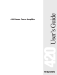
421m User’s Guide
421m AGC-Leveler
Table of Contents
Introduction
1
Chapter 2
Operator Safety Summary
2
Chapter 3
Front & Rear Panel Overview
3
Chapter 4
Installation
6
Chapter 5
Operation
8
Chapter 6
Applications
10
Chapter 7
Specifications
13
Chapter 8
Troubleshooting
14
Chapter 9
Warranty and Service
15
421m
Chapter 1
Rev B.00, 18 February, 1999
Symetrix part number 53421M0B00
Subject to change at without notice.
©1999, Symetrix, Inc. All right reserved.
Symetrix is a registered trademark of Symetrix, Inc.
Mention of third-party products is for informational
purposes only and constitutes neither an endorsement nor
a recommendation. Symetrix assumes no responsibility
with regard to the performance or use of these products.
Under copyright laws, no part of this manual may be
reproduced or transmitted in any form or by any means,
electronic or mechanical, including photocopying,
scanning, recording or by any information storage and
retrieval system, without permission, in writing, from
Symetrix, Inc.
i
14926 35th Ave. West
Lynnwood, WA 98037 USA
Tel (425) 787-3222
Fax (425) 787-3211
Email [email protected]
Chapter 1
Introduction
The Symetrix 421m is a wide-range AGC-Leveler, a peak limiter, and a downward expander that
features a microphone preamp, eliminating the need for a separate outboard microphone preamp in
some applications. The 421m reduces the dynamic range of its input signal by the amount of its
ratio setting. That is, if the ratio setting is 2:1, then 40 dB of input range turns into 20 dB at the
output. A fast peak limiter puts an absolute ceiling on the output level so you know that peaks are
held to the level that you set. A downward expander reduces the gain when signal levels fall too
low to process, reducing the noise buildup at low signal levels. Speech filters allow a reduction of
reduction the bandpass of the 421m to minimize feedback or amplifier power waste caused by
spurious out-of-band signals.
AGC-Levelers can be used anywhere that you might need to reduce the dynamic range of an audio
signal over a wide range of signal levels. Possible applications include: tape duplication (especially
cassette), driving telephone lines, driving broadcast or STL transmitters, podium or lectern microphones, paging systems, unattended sound systems, and music recording.
The 421m is listed by Underwriters Laboratories Inc. (UL). Samples of this product have been
evaluated by UL and meet the applicable UL Standards for Safety.
Telephone:
(425) 787-3222
Fax:
(425) 787-3211
E-mail:
[email protected]
Website:
www.symetrixaudio.com
DOWNWARD EXPANDER (NR)
THRESHOLD (Vu)
AGC-LEVELER
AUTO-RELEASE
LEVEL
RELEASE
RECOVERY
RATE
OUTPUT LIMITER
RATIO
-35
421m
-20
AGC-LEVELER
TARGET OUTPUT LEVEL
-45
EXPAND
BYPASS
FAST
SLOW
125Hz
6kHz
-8
+15
IN
BYPASS
IN
BYPASS
LIMIT
LOW
HIGH
BYPASS
4:1
DECREASE INCREASE
-15
SYSTEM
BYPASS
STEREO LINK
0
ACTIVE
AUTO
SPEECH CURVE
THRESHOLD (Vu)
2:1
FAST
SLOW
421m
We recommend that you read this manual from cover to cover. Somewhere between the confines of
the two covers you should find the answers to most of your questions. If not, please feel free to
contact our Customer Service department via phone, fax, or e-mail for answers to your questions.
The numbers are:
MASTER
SLAVE
IN
INPUT LEVEL
-54 -48 -42 -36 -30 -24 -18 -12
-6
0VU +6 +12
-54 -48 -42 -36 -30 -24 -18 -12
-6
0VU +6 +12 CLIP
BYPASS
IN
BYPASS
OUTPUT LEVEL
BYPASS
Front panel
421m AGC-LEVELER
AC INPUT
20 WATTS
MAXIMUM
MANUFACTURED IN
LYNNWOOD, WA, USA
STEREO LINK
CONNECT TO
POWER
FABRIQUÉ AUX E.-U. PAR SYMETRIX INC., LYNNWOOD, WASHINGTON.
RÉFÉREZ TOUTE RÉPARATION À UN TECHNICIEN QUALIFIÉ.
BALANCED/UNBALANCED LINE OUTPUT
SIG
GND
BALANCED/UNBALANCED LINE INPUT
EARTH SIG
GND GND
BALANCED MICROPHONE INPUT
LEVEL
TRIM
-10
LEVEL
TRIM
0
+25
+50
PHANTOM
POWER
+48V
OFF
TYPICAL
CONNECTIONS
XLR PHONE SIGNAL
=
=
PIN1 SLEEVE GROUND
XLR PHONE SIGNAL
=
=
PIN2
TIP
HIGH(+)
XLR PHONE SIGNAL
=
=
PIN3 RING
LOW(-)
SYMETRIX 421 ONLY!
(NOT A MIDI CONNECTOR)
Rear panel
1
Operator Safety Summary
Equipment Markings
CAUTION
RISK OF ELECTRIC SHOCK
DO NOT OPEN
TO REDUCE THE RISK OF FIRE OR
SHOCK DO NOT EXPOSE
WARNING: ELECTRIC
THIS EQUIPMENT TO RAIN OR MOISTURE
DE CHOC ELECTRIQUE
AVIS: RISQUE
NE PAS OUVRIR
SEE OWNERS MANUAL. VOIR CAHIER D’INSTRUCTIONS.
No user serviceable parts inside. Refer servicing to qualified service personnel.
Il ne se trouve a l’interieur aucune piece pourvant entre reparée l’usager.
S’adresser a un reparateur compétent.
The lightning flash with arrowhead symbol within an
equilateral triangle is intended to alert the user of the
presence of uninsulated “dangerous voltage” within
the product’s enclosure that may be of sufficient
magnitude to constitute a risk of electric shock to
persons. The exclamation point within an equilateral
triangle is intended to alert the user of the presence of
important operating and maintenance (servicing)
instructions in the literature accompanying the
product (i.e. this manual).
Caution To prevent electric shock, do not use the
polarized plug supplied with the unit with
any extension cord, receptacle, or other
outlet unless the blades can be fully
inserted.
421m
Terms
Several notational conventions are used in this
manual. Some paragraphs may use Note, Caution,
or Warning as a heading. Certain typefaces and
capitalization are used to identify certain words.
These are:
Note
Caution
Warning
CAPITALS
Boldface
Identifies information that needs
extra emphasis. A Note generally
supplies extra information to help
you to better use the 421m.
Identifies information that, if not
heeded, may cause damage to the
421m or other equipment in your
system.
Identifies information that, if
ignored, may be hazardous to your
health or that of others.
Controls, switches or other markings
on the 421m’s chassis.
Strong emphasis.
Important Safety Instructions
Please read and keep these instructions. Heed
and follow all warnings and instructions.
Install in accordance with the manufacturer’s
instructions.
Power Source This product is intended to
operate from a power source that does not apply
more than 250V rms between the power supply
conductors or between either power supply
conductor and ground. A protective ground
2
Chapter 2
connection, by way of the grounding conductor
in the power cord, is essential for safe operation.
Grounding The chassis of this product is
grounded through the grounding conductor of
the power cord. To avoid electric shock, plug the
power cord into a properly wired receptacle
before making any connections to the product. A
protective ground connection, by way of the
grounding conductor in the power cord, is
essential for safe operation. Do not defeat the
safety purpose of the grounding plug. The
grounding plug has two blades and a third
grounding prong. The third prong is provided for
your safety. When the provided plug does not fit
your outlet, consult an electrician for replacement
of the obsolete outlet.
Danger from Loss of Ground If the protective
ground connection is lost, all accessible conductive parts, including knobs and controls that may
appear to be insulated, can render an electric
shock.
Proper Power Cord Use only the power cord
and connector specified for the product and your
operating locale. Use only a cord that is in good
condition. Protect the power cord from being
walked on or pinched, particularly at plugs,
convenience receptacles, and the point where
they exit from the apparatus.
Proper Fuse The user accessible fuse is a part of
the IEC AC inlet connector. The fuseholder
accepts 5 x 20mm diameter fuses. For 117VAC
operation, the correct value is 0.25A, 250VAC,
standard. For 230VAC operation, the correct
value is 0.125A, 250VAC, standard.
Operating Location Do not operate this equipment under any of the following conditions:
explosive atmospheres, in wet locations, in
inclement weather, improper or unknown AC
mains voltage, or if improperly fused. Do not
install near any heat source such as radiators,
heat registers, stoves, or other apparatus
(including amplifiers) that produce heat. Unplug
this apparatus during lightning storms or when
unused for long periods of time.
Stay Out of the Box To avoid personal injury (or
worse), do not remove the product covers or
panels. Do not operate the product without the
covers and panels properly installed. Only use
accessories specified by the manufacturer. Clean
only with a damp cloth.
User-serviceable parts There are no user
serviceable parts inside the 421m. In case of
failure, refer all servicing to the factory. Servicing
is required when the 421m has been damaged in
any way, such as when a power supply cord or
plug is damaged, liquid has been spilled or
objects have fallen into the apparatus, the
apparatus has been exposed to rain or moisture,
does not operate normally, or has been dropped.
Front & Rear Panel Overview
Chapter 3
This chapter provides a basic overview of the 421m by describing the input and output connections, power connection, operating controls, and front panel LED indicators.
Front panel view (left)
DOWNWARD EXPANDER (NR)
THRESHOLD (Vu)
AGC-LEVELER
AUTO-RELEASE
LEVEL
RELEASE
RECOVERY
RATE
RATIO
-35
421m
-20
AGC-LEVELER
TARGET OUTPUT LEVEL
2:1
FAST
SLOW
-45
EXPAND
ACTIVE
AUTO
BYPASS
EXPAND LED
DOWNWARD EXPANDER
THRESHOLD control
FAST
SLOW
LEVELER
ACTIVE LED
LOW
HIGH
BYPASS
RECOVERY RATE
button
AGC AUTO-RELEASE
control
4:1
DECREASE INCREASE
TARGET
OUTPUT LEVEL
RATIO control
DOWNWARD EXPANDER RELEASE control
DOWNWARD EXPANDER THRESHOLD - Determines the level below which the downward
expander operates, which reduces the gain at a 1:2 dB ratio.
At the max CCW setting of the control, the threshold setting is automatic; determined by the
setting of the AUTO-RELEASE control. In this case, the downward expander acts more like a gate
(very high ratio) NOTE: the silence detector thinks that acoustic feedback is silence!
DOWNWARD EXPANDER RELEASE - Determines the rate of decay for the downward expander.
EXPAND LED - Tells when the downward expander is active.
LEVELER ACTIVE LED - Indicates the leveling activity. If the LED is off, then the gain of the AGCLeveler is frozen at the last setting. The signal level where the gain is frozen is determined by the
AUTO-RELEASE LEVEL control.
AUTO-RELEASE LEVEL - Determines the level that the input signal must exceed to allow the AGCLeveler to respond. If the signal level is below this threshold (active LED OFF), then the AGC gain
is frozen and the AGC allows the signal level to fall to zero. This keeps the AGC-Leveler from
“undoing” fades, etc.
Another way to understand this control is to think of it in terms of the minimum signal level
required to make the AGC-Leveler try to maintain the Target Output Level. Once the signal falls
below the AUTO-RELEASE setting, the AGC-Leveler allows the signal to decrease. When the
input signal exceeds the AUTO-RELEASE setting, the AGC-Leveler once again tries to maintain
constant output level.
RECOVERY RATE - Sets the basic recovery-time. Fast for speech, slow for music or music/speech.
Fast might work for music in special applications.
RATIO - Determines the input/output ratio. This control instructs the 421m how aggressively you
want to maintain the target output level. Using a 2:1 ratio, a 2dB drop in the input level results in a
1dB drop at the 421m's output. With a 4:1 ratio, a 4dB drop at the input is limited to a 1dB decrease
at the output. The 421m computes the additional make-up gain needed for the ratio setting and
applies it to the VCA so that the output level doesn’t change with the setting of the ratio control.
TARGET LEVEL - Sets the desired output level.
3
421m
At the max CW setting, the threshold setting is low enough that all signals are above threshold,
therefore the expander is bypassed.
Front panel view (right)
OUTPUT LIMITER
VEL
SPEECH CURVE
THRESHOLD (Vu)
125Hz
STEREO LINK
0
-8
SYSTEM
BYPASS
6kHz
+15
IN
BYPASS
IN
BYPASS
MASTER
SLAVE
LIMIT
E
-15
OUTPUT LIMITER
THRESHOLD LED
IN
INPUT LEVEL
-54 -48 -42 -36 -30 -24 -18 -12
-6
0VU +6 +12
-54 -48 -42 -36 -30 -24 -18 -12
-6
0VU +6 +12 CLIP
BYPASS
IN
BYPASS
OUTPUT LEVEL
BYPASS
SPEECH CURVE filters
(125 Hz high pass,
6kHz low pass)
OUTPUT LIMITER THRESHOLD control
BYPASS button
INPUT LED meter
STEREO LINK button
OUTPUT LED meter
OUTPUT LIMITER THRESHOLD LED - Indicates peak limiting activity.
OUTPUT LIMITER THRESHOLD - Sets the threshold of the peak (ceiling) limiter. This works in
conjunction with the leveler’s ratio and target output level controls. The 421m will not allow the
peak limiter to be set higher than the setting of the target output level control. If you think about it,
it would make no sense if you allowed peaks past the target output level.
421m
SPEECH CURVE FILTERS - The high pass filter (button on the left) has a 12 dB/octave rolloff and
the low pass filter (button on the right) rolls off at 24 dB/octave.
STEREO LINK - Sets the master/slave relationship between 2 units. The normal setting is IN.
BYPASS BUTTON - This control hard-wire bypasses the 421m. If STEREO LINKED, all linked
(slave) units revert to bypass when the bypass button on the master unit is out. On any individual
slave unit that has been STEREO LINKED (STEREO LINK button OUT), this button has no effect.
INPUT LED - This meter indicates the input signal level to the 421m. It is a VU calibrated peak
reading meter.
OUTPUT LED - This meter indicates the output signal level of the 421m. It is a VU calibrated peak
reading meter.
4
Rear panel view (left)
421m AGC-LEVELER
AC INPUT
20 WATTS
MAXIMUM
BALANCED/UNBALANCED LINE OUTPUT
STEREO LINK
MANUFACTURED IN
LYNNWOOD, WA, USA
SIG
GND
CONNECT TO
EARTH
GND
POWER
SYMETRIX 421 ONLY!
(NOT A MIDI CONNECTOR)
FABRIQUÉ AUX E.-U. PAR SYMETRIX INC., LYNNWOOD, WASHINGTON.
RÉFÉREZ TOUTE RÉPARATION À UN TECHNICIEN QUALIFIÉ.
SERIAL NUMBER
AC INPUT connector
STEREO LINK connector
OUTPUT connectors
AC INPUT - This connector accepts nominal AC power sources of 115 volts or 230 volts [see
Appendix A (Specifications) for voltage tolerance ranges]. See chapter 4 (Installation) for details
on the detachable (IEC) power cable.
SERIAL NUMBER - Write this down in a safe place (how about the front of this user's guide?).
While you’re at it, do us a favor and return your completed warranty card. Not only does it
establish your warranty, it helps give us a clue to your future equipment wants, needs, and desires.
STEREO LINK - This 5-pin DIN female connector is used to link two 421ms for stereo operation.
Refer to the STEREO INTERCONNECT section on page 6 for additional information.
Rear panel view (right)
BALANCED/UNBALANCED LINE INPUT
EARTH SIG
GND GND
BALANCED MICROPHONE INPUT
LEVEL
TRIM
LEVEL
TRIM
-10
LINE INPUT
connectors
0
+25
PHANTOM
POWER
+50
MIC INPUT connector
LINE INPUT
LEVEL TRIM
+48V
OFF
TYPICAL
CONNECTIONS
XLR PHONE SIGNAL
=
=
PIN1 SLEEVE GROUND
XLR PHONE SIGNAL
=
=
PIN2
TIP
HIGH(+)
XLR PHONE SIGNAL
=
=
PIN3 RING
LOW(-)
PHANTOM POWER button
MIC LEVEL TRIM
LINE INPUT - These connectors are electronically balanced, line level, bridging inputs. The ¼"
connector tip is high, ring is low, and sleeve is ground. The screw terminal input is wired in parallel
to the ¼" connector.
MICROPHONE INPUT - This connector is a balanced, low impedance input. The female XLR pin 2
is high, pin 3 is low, and pin 1 is ground.
MIC LEVEL TRIM - Adjusts the gain of the microphone preamp from a minimum of 25dB to a
maximum of 50dB.
PHANTOM POWER - Applies or removes microphone phantom power at the MICROPHONE
INPUT connector.
5
421m
OUTPUT CONNECTORS - These are electronically balanced, line level, low impedance outputs.
XLR pin 1 is ground, pin 2 is high, and pin 3 is low. The ¼" connector tip is high, ring is low, and
sleeve is ground. The screw terminal output is wired in parallel to the ¼" and XLR connectors.
Installation
Chapter 4
Before you plug the 421m into a wall socket, carefully read the information in the following chapter.
AC Line Connection
A sticker on the right end of the unit (as viewed from the front) indicates the nominal voltage
setting for the unit as it left the Symetrix factory. If this does not correspond to the voltage setting
for your locale then do not attempt to apply power to the 421m. Instead, return the unit to your
local Symetrix distributor for modification or replacement.
The 421m is shipped from the Symetrix factory with a detachable AC power cable (IEC standard)
included. Depending on the intended destination, the power plug is either the US type (intended
for 115VAC use), or the Europlug type. If the power cable's plug is not right for your locale, then
please contact your local Symetrix distributor for the proper cable.
Once you have determined that the 421m's operating voltage matches that of your locale and you
are ready to begin, follow these steps:
1. Plug the socket end of the power cable into the recessed AC power receptacle on the back of
the 421m.
2. Plug the other end of the power cable into a three-hole grounded outlet or power strip.
421m
Warning:
The 421m is intended to be electrically grounded. It has been provided with a threewire grounding plug - a plug that has a third (grounding) pin. This plug will fit only
a grounded AC outlet. This is a safety feature. If you are unable to insert the plug
into the outlet, contact a licensed electrician to replace the outlet with a properly
grounded outlet. Do not defeat the purpose of the grounding plug!
Mounting In An Equipment Rack
The 421m occupies one rack space (1U) in a standard equipment rack with a width of 19" (48.3cm),
a depth of 6.5"(16.8cm), and a height of 1.75"(4.45cm). Allow at least 4"(10.16cm) behind the unit
for the protrusion of connectors. We recommend you take care not to mount the 421m next to
devices that emit large electromagnetic fields, such as audio power amplifiers. To do so may
compromise the noise performance of the 421m. The 421m has been designed to conform to
mechanical guidelines as described in EIA Standard RS-310-C and IEC Recommendation 297.
Audio Input Connections
The 421m's line input connections are via a standard ¼" phone jack, and barrier terminals. The
421m's microphone input connection is an XLR female. For optimum system performance we
recommend that the 421m be connected to balanced signals. If this is not practical in your situation, then you may connect to unbalanced sources.
Audio Output Connections
The 421m's audio output connections are via standard male XLR jack, ¼" phone jack, and barrier
terminals located on the rear panel. For optimum system performance we recommend that the 421m
be connected to balanced devices. If this is not practical in your situation, then you may connect
to unbalanced devices.
Use any combination of the input and output connections. All of the input connections are
paralleled. The XLR output connector and the balanced screw terminal outputs are paralleled. The
unbalanced output is paralleled from the + screw terminal output. The 421 wants line level signals,
such as those found at the output of a CD player, cassette machine, mixer output, mixer channel
insert jack, etc.
6
Stereo Interconnect
To stereo-link two 421m's, interconnect the STEREO LINK jacks found on the rear panels of the
units using a five-pin DIN male to DIN male patch cord (Symetrix p/n 037010). This looks like a
MIDI cable, and a MIDI cable may actually work if all five pins are actually connected to each
other.
Note:
Although the stereo-interconnect cable looks like a MIDI cable, it isn’t. There is nothing
remotely resembling MIDI inside or between two 421m’s. If you connect either connector
to a MIDI device, it probably won’t harm anything, but it definitely won’t work.
Decide which unit is the master and which unit is the slave (using force only if absolutely necessary) and set the front panel MASTER/SLAVE switches accordingly. In stereo-mode the slave
unit’s controls are disabled and only the master unit controls affect operation. The following
diagram shows how to stereo-link two 421m's.
If there is no master unit connected via the Stereo Link connectors, the slave unit (any
unit with it's MASTER/SLAVE switch in the OUT position) remains in bypass mode,
regardless of the setting of its bypass switch.
421m
Note:
7
Operation
Chapter 5
Initial Setup
Set the front panel controls as follows:
DOWNWARD EXPANDER THRESHOLD
Bypass
DOWNWARD EXPANDER RELEASE
Straight up
AGC-LEVELERAUTO-RELEASELEVEL
Straight up
RECOVERYRATE
In
RATIO
4:1
TARGET OUTPUT
Straight up
SPEECH CURVE (125 Hz)
Out
SPEECH CURVE (6kHz)
Out
Apply an input signal to the 421m. Observe the input and output meters; there should be activity.
The input meter reads the actual input signal. The output meter reads the actual output signal.
Both meters are peak responding and are calibrated in VU (0 VU = +4 dBu = 1.23V RMS).
Set the AGC-Leveler by first adjusting the TARGET OUTPUT LEVEL control for the output level
required. Next, decrease the setting of the RATIO control until you obtain the desired amount of
dynamic range reduction. Speech tolerates higher ratios than music. Use a higher ratio (4:1) for
stronger leveling action. The difference between the two meters shows what the 421m is doing. Remember that a 1:1 ratio setting amounts to BYPASS for the AGC-Leveler. Set the RECOVERY RATE
button as required by the program material (starting point: FAST = speech, SLOW = music, SLOW
= speech and music).
421m
In sound reinforcement applications, set the AUTO-RELEASE LEVEL control to limit the pickup
“range” of the microphone. Lower (more CCW) settings will increase the pickup range (the level
setting is lower, therefore the AGC-Leveler will track lower level signals), and higher settings will
force the user to be more “on-mike.”
In recording, broadcast or tape duplication applications, the AUTO-RELEASE LEVEL control sets
the minimum signal level that the AGC-Leveler will track. If the input signal is music with a long
fade, the AGC-Leveler interprets the fade as a decrease in signal level and raises the gain to try to
maintain the level set by the TARGET OUTPUT LEVEL control. In effect, the AGC-Leveler “undoes” the fade, which may or may not be allowable. The AUTO-RELEASE LEVEL control sets how
far the signal level can fall before the AGC-Leveler stops trying to raise the gain. More CCW settings lower this level, which may be what you want if you’re trying to recreate the long piano chord
heard at the end of the Beatles song, "A Day In The Life".
Set the downward expander during program pauses to minimize noise buildup by adjusting the
Threshold control until the expand activity LED illuminates. Set the RELEASE control for the desired release rate.
Use the AUTO position of the DOWNWARD EXPANDER THRESHOLD control for situations
where the input signal is noisy (hum, hiss, or feedback). In AUTO mode the expander tracks the
AGC-Leveler’s internal auto-release monitor. When the AGC-Leveler releases, the expander begins
working at the rate set by the RELEASE control. If the input signal contains acoustic feedback, and
nothing else above the auto release hold, the auto-release monitor ignores it, which effectively
stops the feedback before it has a chance to grow into something potentially damaging.
Set the OUTPUT LIMITER by adjusting the THRESHOLD control either for the absolute maximum
output level desired (as read on the threshold control’s panel scale) or as indicated on the peak-responding output meter.
Set the SPEECH CURVE buttons as necessary and as required by the situation. The 125Hz button
removes ''boominess'' and some of the proximity effect caused by close-talking a single-D cardioid
microphone (such as a Shure SM-58), without making voices sound thin. The 6kHz button removes
sibilance and high-frequency feedback without causing “telephone voice.”
8
Note:
Do not use pink noise or sine-waves for setup. It simply will not work (the ARM circuitry
will think your signal is noise). Use speech or music.
Helpful Hints
Microphone Techniques
Note: The ability of the expander to discriminate between wanted and unwanted signals is partially
determined by mic technique. Be particularly careful of high frequency sounds entering the side or
rear pattern of a cardioid mic. Most cardioid mics exhibit a sharply rising off-axis response characteristic at higher frequencies. Check the off-axis curves in the manufacturer's literature. If there's
only a 3dB - 6dB difference between the on-axis (frontal) response and the off-axis (side) or rear response in the 5kHz to 10 kHz region, high frequency sounds will be picked up by the mic, thereby
possibly preventing the downward expander from reducing unwanted sounds.
Use the mic's directional pattern to keep unwanted sources as far off-axis as possible. Do everything you can to discriminate against unwanted sounds through good mic technique. The sounds
picked up by an individual mic must be primarily the sound of the desired signal or the 421m's
downward expander won't be able to discriminate between signal and noise.
Optimizing Control Settings
When searching for optimum control settings, here are a few rules to follow:
AUTO-RELEASE LEVEL (ARL): This control determines the signal level needed to cause gain release in the AGC-Leveler. A suggested method of setting it is, with no signal present, increase the
setting of the ARL control until the green ACTIVE LED extinguishes. Then, further increase the
control setting slightly.
For musical signals use the SLOW setting of the RECOVERY RATE button. Set the AUTO-RELEASE LEVEL control so that the ACTIVE LED is extinguished during low level musical passages,
fade-outs, or moments of silence.
DOWNWARD EXPANDER: When using the AUTO setting of the downward expander, first set
the AUTO-RELEASE LEVEL control in the AGC-Leveler section. Then use the expander's RELEASE control to prevent expander action during short pauses.
General PA System Considerations
In a public address system, it is important to ensure that feedback cannot occur when the AGCLeveler reaches a state of maximum gain; for instance, when the 421m is trying to boost the volume
of a very quiet voice. Avoid this by talking into the mic just loud enough for the ACTIVE LED to
light. If you hear feedback, then raise the AUTO-RELEASE LEVEL until the feedback dies. Lowering the RATIO will also help. Remember: The ACTIVE LED does not have to be on constantly
while signal is present. In fact, depending on your circumstances, you may elect to set the AUTORELEASE LEVEL high enough to prevent the 421m from responding to all soft voices.
Stereo Link And Bypass Switching
The STEREO LINK and BYPASS buttons interact. In stereo mode, the designated master unit
takes over all functions for both units, including in/bypass switching.
If the STEREO LINK button is in the out position, the 421m is in slave mode which means the 421m
gets its commands via the link cable from the master unit.
Note: If a 421m is placed in SLAVE mode and is not connected to another 421m via a linking cable,
the unit will remain in BYPASS mode regardless of the setting of its BYPASS button. If there is a master
unit connected, then the BYPASS button on the master determines the status of the slave.
9
421m
AGC-LEVELER: The FAST setting of the RECOVERY RATE button is best suited for speech signals. Use the SLOW setting for musical or noisy signals or if you want the gain changes to be as
unobtrusive as possible.
The RATIO control determines how much of the input signal's dynamic range makes it to the output. We recommend starting at 4:1, so you can clearly hear the effect, and then reduce the ratio if
necessary.
Applications
Chapter 6
An AGC-Leveler has many applications in recording studios, auditoriums or theatres, commercial
or industrial PA systems, tape duplication systems, and broadcast. Here follows a small sample of
applications.
Broadcast Telephone Line Driver
At sometime or another every broadcast engineer ends up having to send audio down a telephone
line. Of course, you need to keep levels hot, but if you hit the line too hard the phone company
frowns. It's good practice to ensure that there is a hard limit to any signal that ends up going down
a phone line. The 421m is well suited to the task of unobtrusive, yet unyielding control of audio
levels.
As a starting point, use the SLOW recovery rate, low RATIO (2:1), and a low AUTO-RELEASE
LEVEL. Set the TARGET LEVEL control for the desired average level into the line, and then dial in
enough peak limiting to keep the peaks under control. You may want to back the TARGET LEVEL
off slightly so that you don't need as much peak limiting. Peak limiters are more inaudible if you
only limit occasional peaks.
Conference or Courtroom Recording
If you're recording conferences or courtroom proceedings, you are faced with the same problem at
the lectern microphone; i.e., some people speak too softly while others are too loud. If possible,
install a separate 421m on each microphone and feed the outputs of the 421m's into the line inputs
of your mixer.
If separate 421m's for each mic are not an option, then place a single 421m between the mixer output
and the input of the tape recorder.
421m
Foreground Music
The CD changer has propelled canned music into a new era. The problem, of course, is the wide
dynamic range of CD's coupled with the fact that different CD's as mastered at diverse and unpredictable levels. Most CD's simply have too much range for foreground or background music
applications. The 421m helps reduce the overall dynamic range, while retaining some semblance of
the music's original dynamics. You can link two units together for stereo if desired.
There's probably no need to use the downward expander in this application, so turn the THRESHOLD control to the BYPASS position. Set the AGC-Leveler RATIO to 2:1 and use the SLOW
recovery rate setting. Set the AUTO-RELEASE LEVEL to 9:00 o'clock or lower. Experiment with the
PEAK LIMITER threshold, and use the PEAK LIMITER only if necessary.
Americans with Disabilities Act
The American Disabilities Act (ADA) of 1990 (Public Law 101-336) affects any of us who supply
equipment to or operate public gathering places. There are five major aspects (Titles) to this law, all
of which have staged implementation dates.
Title I deals with employment issues, Title II deals with public services, Title III deals with public
accommodations and services operated by private entities, Title IV deals with telecommunications,
and Title V deals with miscellaneous issues. Of particular interest to sound system providers or
installers is Title III, which says that many of the places where you find sound systems must
provide assisted listening devices for persons with sensory impairment. Some of the solutions
employed are: headphone jacks at certain seats, low powered AM or FM transmitters broadcasting
to Walkman (R) type radios or to facility-supplied radios, and infrared transmission systems.
Regardless of the transmission method, these systems all require a signal of reduced dynamic
range so that the users can hear both the softest and loudest parts of a performance. The 421m is
ideally suited to this application. Try moderate to high ratios (2:1 and up), and long release times.
Pick an AUTO-RELEASE level that keeps the AGC action somewhat unobtrusive. Use the peak
limiter to keep the transmitter out of clipping.
10
Lectern-Mounted Microphones
A common and thoroughly vexing problem is that of the ubiquitous lectern microphone. A staple
of hotels, public meeting places, courtrooms, and churches, the podium microphone gets used and
misused by one and all.
Anyone who uses a microphone has their own idea of how and where to place the microphone
(relative to their lips, of course) and how they should speak into it. Some get their cues from TV
(which any self-respecting audio person knows is usually wrong), and some just make it up as they
go. Some stick the mike near their navel, just like on TV (or is it that TV-news-types have their
vocal chords somewhere new?), and others try to use it for a snack. You get the idea. What this
means to you is roller-coaster audio levels. Try the 421m. It will do for a lectern or other announce
microphones what no compressor has ever done before: consistent audio levels with increased
freedom from feedback.
Some hints: use moderate ratios (3:1 to 4:1) unless you want a really “in your face” sound. Use
either or both of the speech filter switches. The AUTO-RELEASE LEVEL affects the size of the
microphone’s “pickup circle.” More CCW settings expand the circle, allowing the 421m to raise
lower level voices more (remember, it won’t keep them from sounding distant or off-mike!). Higher
settings restrict the pickup range of the microphone, so a weak talker won’t be picked up as well
unless they move-in on the microphone to cause the gain to readjust to their voice level. In noisy
environments, try a higher (more clockwise) setting. You can use the downward expander in AUTO
mode to gate the mike off when idle. Ensure that the TARGET OUTPUT LEVEL isn’t high enough
to cause feedback when the AGC-Leveler has fully engaged (you can force a release by quickly
turning the AUTO-RELEASE LEVEL control and then returning it to its former setting.
Have you ever mixed live sound for someone who just can’t play at the right level? They’re usually
too soft when playing rhythm, and too loud when playing leads. A 421m can help you out. Connect
the 421m into the mixer’s channel insert jack, use a relatively low RATIO setting, use the expander
if you need to. Remember that lower ratio settings allow for more dynamics than the higher settings
which means more difference between soft and loud. This trick also works on microphones that are
sung into and used for announcements. The 421m keeps the announcements audible without the
worry of forgetting to bring the fader down during a song. Again, use a low RATIO setting around
2:1. If you try this on a submix, be careful because the large number of microphones involved
makes it that much easier to push the sound system into feedback.
Mixdown
You can use the 421m during mixdown for a number of different things. For voiceover's let the 421m
ride the level of the announcer, while you set the basic announcer to music-bed ratio, or, let the
421m ride the music-bed, while you ride the announcer’s level. Process background vocals with
the 421m. It will keep them consistently hot, without making them sound squashed (unless that’s
what you want). Try using the 421m on individual instruments as a way of keeping their level more
consistent without radically altering their timbre.
Paging Systems
Just like the poor lectern mike, paging systems suffer from the same ills. It really doesn’t matter if
the audio begins life in a telephone system, or if you have a dedicated paging mike. Every user has
their own idea of how to use the mike. You can fight them and win with the 421m AGC-Leveler.
Secondary Sound System Feeds
Many sound systems derive secondary feeds for ancillary systems that serve related areas of a
facility. In arenas or large stadiums this might be the outer concourses, PA shadow zones, concession areas, rest rooms, dressing rooms, etc. In a church it might be the lobby or cry room. In a TV
studio, it could be the IFB (interrupted foldback) system.
11
421m
Live PA
Tape Duplication
Anytime you change recording media, especially between a professional format and a consumer
format (how about DAT to consumer cassette?), patch a 421m into the recording chain to perform a
gentle squeeze to match the signal level to the input of the next device and peak limiting. Try 2:1
RATIO; set the TARGET OUTPUT LEVEL control for the average level that you need and use the
limiter to control the peaks.
Many churches record the Pastor’s message (sermon) and make it available on tape by the end of
the service. Considering the speed with which this must occur, a 421m might be just the thing to
keep the average levels hot, while still preventing overload.
Teleconferencing
Many teleconference users want to record the content of the conference. Of course, audio levels
are all over the map (one participant shouts, another is timid...). Try a 421m between the audio mixer
and one track of the tape machine, and another between the telephone interface and another track
of the tape machine. Using separate 421m's and separate tape tracks will help if and when someone
tries to transcribe the conference. Keeping things separate also helps negate the 421m's tendency
to bring the telephone interface’s leakage (trans-hybrid loss) up to the same level as the caller,
which isn’t a good idea. The 421m helps by keeping the signal levels more consistent from caller to
caller, which is a good idea.
Theatre and Auditorium Cue Systems
421m
An auditorium cue system consists of a microphone(s) mounted in the audience area of a theatre or
auditorium that feeds an amplifier that drives speakers located in the backstage areas of the hall.
The potential dynamic range in this application is tremendous, ranging from an empty room to an
audience on their feet making a plea for an encore.
A 421m, in conjunction with close miking of the person calling the cues, can work wonders keeping
this sort of system under control; keeping the level high enough to be audible, and low enough to
not be annoying. The downward expander can reduce the level when the room is very quiet, to
eliminate electronic noise, yet open up if someone speaks.
Post Production
A 421m can be invaluable in post production. How about:
Use the 421m when transferring location sound tapes. If you keep the ratio low, you’ll gain
consistency with a minimum loss of dynamic range.
Use multiple 421m's to keep various mix elements audible...Try one on FX or Foley, and on dialog.
If you’re creating something that will be heard in a specific environment, consider using a 421m to
preprocess your mix for that environment. For instance, suppose you’re making a point-ofpurchase video that will heard in a noisy department store, over a semi-ordinary television set.
With your mixer or an outboard EQ, give the dialog a good dose of 2.5k to 5k presence boost to
make it cut through the noise. Then process the overall mix through the 421m with a 3:1 ratio. This
will keep the overall level hot but consistent, and the combination of presence boosting and overall
level control will make your product audible in spite of the adverse environment in which it is
represented.
Be sure to check the previous section entitled “Mixdown” for additional tips and hints.
12
Chapter 7
Specifications
421m Specifications
¼" TRS jack and screw terminals,
20k Balanced Bridging
Mic Input
XLR-female, 10k Balanced Bridging
Outputs
XLR-male, screw terminals, 200 Ohm Source
Impedance, Differentially Balanced, +23 dBm maximum level
TS phone, Unbalanced, +18 dBm maximum level
Bypass
Relay controlled, hard-wire bypass in power off
and bypass conditions
Sidechain
TRS phone, Unbalanced Send and Receive,
1000 Ohm Source Impedance, 10k Input Impedance
Tip=Receive, Ring=Send
Downward Expander
Ratio
Threshold
Attack Time
Release Time
AGC-Leveler
Ratio
Auto Release Threshold
Attack Time
Release Time
Target Output
Range
Peak Limiter Ratio
Threshold
Attack Time
Release Time
1:2
-50VU (bypass) to -20VU (Auto Threshold)
1 ms
Program dependant, 0.3 - 3.5 seconds
depending on amount and duration
1:1 to 4:1
-70 dBu to -30 dBu
approximately 1 ms
Program dependant, 500 ms - 5 seconds
depending on amount and duration
+20 dB
10:1
-15VU to +23VU (bypass)
1 ms for 90% gain reduction
0.8 seconds
Mic Preamp
Gain Range
Impedance
Max Input Level
THD+Noise (gain control fully clockwise)
Phantom Power
CMRR
+15 dB to +45 dB
10k Ohms
+8 dBu
-85 dBu
48V (±2)
>80 dB (10 Hz - 20 kHz)
Sonics
Frequency Response 20 to 50 kHz, +4 dBm (+0, -1 dB), (+0, -3 dB mic)
Harmonic Distortion
<0.05% 20 Hz to 20 kHz, +4 dBm,
30 kHz bandwidth
Typically <0.01% @ 1000 Hz
Residual Noise
-90 dBu, 20 kHz noise bandwidth,
rms responding meter
Speech Curve
Type
Switch selected cutoff filters allow tailoring LF and/or HF
response for speech applications
Frequencies
LF=125 Hz, 12 dB/octave; HF=6 kHz, 24 dB/octave
Input/Output Metering
Type
Range (min to max)
Ballistics
Calibration
Physical
Size (hwd)
Shipping Weight
Electrical
Connector
Power Requirements
Note:
LED Bar Graph, 12 steps + clip
66 dB
Peak
0 dB=0VU=+4 dBm=1.23V
1.72 x 19 x 6.25 inches,
4.37 x 48.26 x 15.875 centimeters
8 lbs (3.63kg) net
EC 3-pole
117V nominal, 107 to 125V AC,
50 to 60 Hz, 10 watts
220V AC, 50 Hz, 10 watts
The maximum operating ambient temperature is
25 degrees C.
421m Architects and Engineers Specifications
The Automatic Gain Control (AGC) shall be a single channel model that reduces the dynamic range of wide range, wideband audio signals, providing
peak limiting, downward expansion and bandpass limiting filters. The AGC shall occupy one rack space (1U).
The AGC shall be capable of controlling audio signals ranging from -70 dBu to +24 dBu and reducing their range by an input/output ratio ranging
from 1:1 to 4:1. The input/output ratio shall be adjustable via a front-panel control. Fast/slow response speed switching shall be provided to
accommodate speech and music sources. A target output level control shall be provided to shift the level of the output signal over a nominal ±20 dB
range. The release time of the AGC shall be controlled by the presence of input signal and the signal sensor shall be capable of discriminating between
music/speech and random noise or pure tones. The threshold level of the signal sensor shall be adjustable via a front panel control and the presence of
signals above the threshold setting shall be indicated via a green LED.
The AGC shall also contain an integral peak limiter having at least a 10:1 ratio and adjustable threshold level. A green LED indicator shall be provided to
indicate peak limiter activity. The peak limiter threshold shall determine the absolute maximum output amplitude of the AGC-Leveler regardless of other
conditions.
The AGC shall also contain an integral downward expander having a 1:2 expansion ratio with threshold and release time controls. Furthermore, the
downward expander shall be capable of operating automatically via the signal sensor circuitry. A green LED indicator shall be provided to indicate
downward expander circuit activity.
Bandpass limiting filters shall be provided having a lowpass characteristic of 24 dB/octave at 6 kHz and a highpass characteristic of 12 dB/octave at 125
Hz. Both filters shall be capable of being used individually or simultaneously.
The AGC shall provide identical peak responding input and output level meters. These meters shall be capable of responding to signals ranging from 54 VU to +12 VU (-50 dBu to +16 dBu). An output clipping indicator shall be provided.
The AGC shall provide facilities for stereo-coupling two units via a shielded 5-pin DIN male-to-male cable. A front panel switch shall designate which unit
is the master and which unit is the slave.
The line level inputs shall be active balanced bridging designs terminated with ¼" TRS female and screw terminals. The mic level input shall also be an
active balanced bridging design using a three pin XLR female (AES/IEC standard wiring). The input circuitry shall incorporate RFI filters. The outputs
shall be active balanced designs having equal source impedances and terminated with 3-pin XLR (AES/IEC standard wiring) and screw terminals. A
separate ¼" TRS jack shall provide an unbalanced output.
The balanced line level inputs shall accommodate +24 dBu signals without distortion, and the balanced outputs shall be capable of delivering +23
dBm into a 600-ohm load. The mic level input shall accommodate +8dBu signals. There shall be separate gain trim controls for the mic and the line
inputs and the mic input shall provide 48v phantom power.
Overall frequency response shall be 20 Hz to 20 kHz, ±1dB, measured at +4 dBm output. There shall be no more than 0.02% harmonic distortion,
measured under the following conditions: +4 dbu input, +4 dBm output, BYPASS switch out, 1000 Hz. Residual noise output shall be no greater than 90 dBm, measured with a 20 kHz noise bandwidth.
When the unit is inoperative (either by loss of power, or via the BYPASS switch), the inputs and outputs shall be wired together. There shall be no
transients transmitted to the output terminals during either turn-on, turn-off, or bypass operation (unless something upstream generates transients).
Access to the AGC’s sidechain shall be provided via a single ¼" TRS female connector. The ring connection shall be the sidechain output and the tip
connection shall be the sidechain return.
The AGC shall be capable of operating by means of its own built-in power supply connected to 115V nominal ac (105 to 130V) 50/60 Hz (230V
nominal, 210 to 260V ac, 50 Hz where applicable). The AGC shall be listed by Underwriters Laboratories Inc. (UL) or other equivalent nationally
recognized safety testing agency.
The unit shall be a Symetrix Incorporated model 421m AGC-Leveler.
13
421m
Connectors
Line Inputs
Troubleshooting
Chapter 8
No output signal:
Check cables and connections.
Determine that there really is a signal coming from the source and that it is getting to the 421m.
Verify cables by patching input and output connections together at the unit.
Check for AC power presence.
Check input by plugging headphones halfway into the sidechain jack and listening for input
signal (this verifies that the unit is receiving signal).
Check output by plugging headphones into output jack.
Check downward expander threshold setting; it may be too high for the current signal level.
Stuck in bypass mode:
Check setting of the STEREO LINK button. In single unit (mono) systems, on independently
operating units and on master units, the switch should be in the IN position.
No limiter action:
Check the threshold control setting. Signal levels may be too low. Don't try to calibrate with
sine waves. Use speech or music.
Distortion:
Is the incoming signal already distorted? Listen “up stream” from the 421m (or manually place
the unit in BYPASS mode) to determine that you are feeding it a clean signal.
421m
Buzz in the output:
Check input and output connector wiring.
Check for ground loops between interconnected system equipment.
Are all system components on the same AC ground?
Noise (hiss):
Check input signal levels and input level control settings. The input may be too low in level. If
so, boost the signal from your console or input source.
Is the input signal already noisy? Listen “up stream” from the 421m to determine if you are
feeding it a clean signal.
The 421m doesn't power up or doesn't respond properly:
Consult a qualified service technician or the Symetrix factory.
Note:
Repeated fuse blowing is a sure sign of electronic distress. Unplug the unit and make
arrangements for repair.
Warning:
The fuse is located internally and lethal voltages are present inside the chassis. The
fuse is not considered user-serviceable. If the fuse is blown, the 421m probably
needs repair.
14
Chapter 9
Warranty & Service
421m Limited Warranty
Symetrix, Inc. expressly warrants that the product will be free from defects in material and workmanship for one (1) year. Symetrix's obligations under this warranty will be limited to repairing or
replacing, at Symetrix's option, the part or parts of the product which prove defective in material or
workmanship within one (1) year from date of purchase, provided that the Buyer gives Symetrix
prompt notice of any defect or failure and satisfactory proof thereof. Products may be returned by
Buyer only after a Return Authorization number (RA) has been obtained from Symetrix. Buyer will
prepay all freight charges to return the product to the Symetrix factory. Symetrix reserves the right
to inspect any products which may be the subject of any warranty claim before repair or replacement is granted. Symetrix may, at its option, require proof of the original date of purchase (dated
copy of original retail dealer's invoice). Final determination of warranty coverage lies solely with
Symetrix. Products repaired under warranty will be returned freight prepaid via United Parcel
Service by Symetrix to any location within the Continental United States. Outside the Continental
United States, products will be returned freight collect.
The foregoing warranties are in lieu of all other warranties whether oral, written, express, implied or
statutory. Symetrix, Inc. expressly disclaims any IMPLIED warranties, including fitness for a
particular purpose or merchantability. Symetrix's warranty obligation and buyer’s remedies hereunder are SOLELY and exclusively as stated herein.
This limited warranty, with all terms, conditions and disclaimers set forth herein, shall extend to the
original purchaser and anyone who purchases the product within the specified warranty period.
Warranty Registration must be completed and mailed to Symetrix within thirty (30) days of the date
of purchase.
Symetrix does not authorize any third party, including any dealer or sales representative, to assume
any liability or make any additional warranties or representation regarding this product information
on behalf of Symetrix.
This limited warranty gives the buyer certain rights. You may have additional rights provided by
applicable law.
Limitation of Liability
The total liability of Symetrix on any claim, whether in contract, tort (including negligence) or
otherwise arising out of, connected with, or resulting from the manufacture, sale, delivery, resale,
repair, replacement or use of any product will not exceed the price allocatable to the product or any
part thereof which gives rise to the claim. In no event will Symetrix be liable for any incidental or
consequential damages including but not limited to damage for loss of revenue, cost of capital,
claims of customers for service interruptions or failure to supply, and costs and expenses incurred
in connection with labor, overhead, transportation, installation or removal of products, substitute
facilities or supply houses.
15
421m
This Symetrix product is designed and manufactured for use in professional and studio audio
systems and is not intended for other usage. With respect to products purchased by consumers
for personal, family, or household use, Symetrix expressly disclaims all implied warranties
including but not limited to warranties of merchantability and fitness for a particular purpose.
Servicing the 421m
If you have determined that your 421m requires repair services and you live outside of the United
States, please contact your local Symetrix dealer or distributor for instructions on how to obtain
service. If you reside in the U.S. then proceed as follows.
Return authorization
At the Symetrix factory, Symetrix will perform in-warranty or out-of-warranty service on any
product it has manufactured for a period of five years from date of manufacture.
Before sending anything to Symetrix, please contact our Customer Service Department for a Return
Authorization (RA) number. The telephone number is (425) 787-3222, Monday through Friday,
8AM (800 hours) through 4:30 PM (1630 hours), Pacific Time.
In-Warranty Repairs
To get your 421m repaired under the terms of the warranty:
1. Call us for an RA number.
2. Pack the unit in its original packaging materials.
3. Include your name, address, daytime telephone number, and a brief statement of the problem.
4. Write the RA number on the outside of the box.
5. Ship the unit to Symetrix, freight prepaid. We do not accept freight collect shipments.
Just do these five things, and repairs made in-warranty will only cost you one-way freight charges
only. We’ll pay the return (surface) freight.
421m
If you choose to send us your product in some sort of flimsy packaging, we'll have to charge you
for proper shipping materials. If you don't have the factory packaging materials, then do yourself a
favor by using an oversize carton, wrap the unit in a plastic bag, surround it with bubble-wrap, and
place it in the box surrounded by Styrofoam peanuts. Be sure there is enough clearance in the box
to protect the rack ears (you wouldn't believe how many units are returned with bent ears). We
won't return the unit in anything but Symetrix packaging for which we will have to charge you. Of
course, if the problem turns out to be operator inflicted, you'll have to pay for both parts and labor.
In any event, if there are charges for the repair, you will pay for the return freight. All charges will
be COD unless you have made other arrangements (prepaid, Visa or Mastercard).
Out-of-Warranty Repairs
If the warranty period has passed, you'll be billed for all necessary parts, labor, packaging materials, and freight charges. Please remember, you must call for an RA number before sending the unit
to Symetrix.
16
17
421m
421m
18
Symetrix, Inc.
14926 35th Ave. West
Lynnwood, WA, 98037-2303
USA
Tel: (425) 787-3222
Fax: (425) 787-3211
Website: http://www.symetrixaudio.com
Email: [email protected]