1
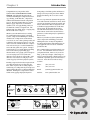
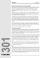
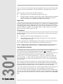
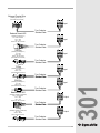
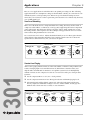
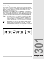
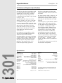
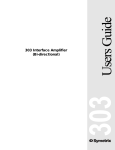
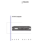
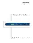
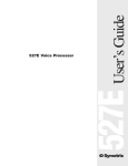
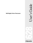
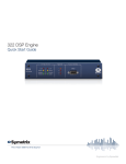
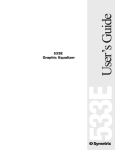
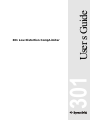
User s Guide
301
301 Low Distortion Comp/Limiter
Table of Contents
Introduction
1
Chapter 2 Operator Safety Summary
2
Chapter 3 Fast Setup
3
Chapter 4 Tutorial
4
Chapter 5 Front Panel Overview
7
Chapter 6 Rear Panel Overview
8
Chapter 7 Connecting to Other Gear
9
Chapter 8 Applications
12
Chapter 9 Troubleshooting
15
Chapter 10 Specifications
16
Chapter 11 Warranty and Service
17
Chapter 12 Declaration of Conformity
19
301
Chapter 1
Rev A.1, 15 June, 1998
Symetrix part number 53301-0A01
Subject to change at our whim and fancy without
notice.
'1998, Symetrix, Inc. All right reserved.
Symetrix is a registered trademark of Symetrix, Inc.
Mention of third-party products is for informational
purposes only and constitutes neither an endorsement nor
a recommendation. Symetrix assumes no responsibility
with regard to the performance or use of these products.
Under copyright laws, no part of this manual may be
reproduced or transmitted in any form or by any means,
electronic or mechanical, including photocopying,
scanning, recording or by any information storage and
retrieval system, without permission, in writing, from
Symetrix, Inc.
i
6408 216th St. SW
Mountlake Terrace, WA 98043 USA
Tel (425) 778-7728
Fax (425) 778-7727
Email: [email protected]
Chapter 1
Introduction
Congratulations on your purchase of the
Symetrix 301 LOW DISTORTION COMP/
LIMITER. The Symetrix 301 represents an
enormous breakthrough in compression technology, allowing, for the first time, compression
without added distortion from the compression
process. The single-channel 301 gives you the
ability to apply compression, to smooth out
dynamic levels, or to apply limiting, when you
need hard-line control over signal levels. The
Symetrix 301 does all this, while occupying only
half the width of one rack space.
from getting so loud that speakers and horns are
damaged, and can provide protection to human
hearing from damage due to excessive sound
levels.
For ease of operation, the Symetrix 301 provides
a selectable automatic attack/release mode, which
generates predetermined compression attack and
release characteristics that are designed to work
well with most program material. For the more
advanced user, the Symetrix 301 provides a
selectable manual attack/release mode, which
allows utmost control of the attack and release
parameters, so that settings may be optimized to
the user s taste.
Whether you work with broadcast, recording,
live sound reinforcement, paging or playback
systems, compression and limiting are extremely
valuable tools. Compression can smooth out
vocal levels, to create a more pleasing sound, and
to allow the audio engineer to squeeze every last
decibel out of the available headroom. Compression can be used to give vocals and instruments,
such as the bass guitar, more punch . Compression also helps to even out the different speaking
levels of the various people making page
announcements over a paging system. It helps to
even out varying source levels (such as the
differences in level between various CD s, or the
difference in level between a CD player and a
cassette tape player) in music playback systems.
Whatever your audio needs, the Symetrix 301
offers compression and limiting power while
utilizing innovative circuitry for unparalleled
freedom from distortion. Only minimal space in
your equipment rack is needed to contain this
powerhouse unit.
Limiting can protect the broadcast engineer from
exceeding the broadcast level allowed by the
FCC, and it can protect the recording engineer
from having a recording ruined by an unexpected
signal peak that drives the recording medium into
distortion. Limiting also can protect live sound
reinforcement, paging and playback systems
Phone:
(425) 778-7728
Fax:
(425) 778-7727
Email:
[email protected]
Website:
www.symetrixaudio.com
COMPRESSOR/LIMITER
THRESHOLD (dBu)
ATTACK
-10
50mS
301
LOW DISTORTION
COMP/LIMITER
-25
+5
25mS
AUTOMATIC
ATTACK/RELEASE
70mS
OUTPUT
RELEASE
RATIO (X:1)
.5 Sec
4
AUTOMATIC
MANUAL
.25 Sec
2 Sec
GR
+20
500uS
100mS
50mS
4 Sec
2.5
8
BYPASS
GAIN (dB)
0
-3dB
-6dB
-12dB
-40
301
We recommend that you read this manual coverto-cover. You will find the answers to most of
your questions inside. However, if you are in a
hurry, go directly to Chapter 3 (Fast Setup). It
will get you started quickly. Should you have any
comments or questions, please do not hesitate to
contact us. Your calls and e-mail are always
welcome.
10
-7.5
+7.5
CLIP
-18dB
-15
+15
PWR
Front panel
OUTPUT
INPUT
MANUFACTURED BY SYMETRIX INC. LYNNWOOD, WA USA
POWER
INPUT
CONNECT TO
SYMETRIX PS-3
OR PS-3E POWER
SUPPLY ONLY.
THIS PRODUCT CONTAINS NO USER SERVICABLE PARTS.
FABRIQUÉ AUX E.-U. PAR SYMETRIX INC., LYNNWOOD, WASHINGTON.
RÉFÉREZ TOUTE RÉPARATION À UN TECHNICIEN QUALIFIÉ.
Rear panel
1
Operator Safety Summary
The information in this summary is intended
for persons who operate the equipment as well
as repair personnel. Specific warnings and
cautions are found throughout this manual
wherever they may apply.
The notational conventions used in this manual
and on the equipment itself are described in the
following paragraphs.
Chapter 2
Caution
Identifies information that, if not
heeded, may cause damage to the
301 or other equipment in your
system.
Warning
Identifies information that, if
ignored, may be hazardous to
your health or that of others.
CAPITALS
Controls, switches or other
markings on the 301 s chassis.
Boldface
Strong emphasis.
Equipment Markings
CAUTION
RISK OF ELECTRIC SHOCK
DO NOT OPEN
TO REDUCE THE RISK OF FIRE OR
SHOCK DO NOT EXPOSE
WARNING: ELECTRIC
THIS EQUIPMENT TO RAIN OR MOISTURE
DE CHOC ELECTRIQUE
AVIS: RISQUE
NE PAS OUVRIR
SEE OWNERS MANUAL. VOIR CAHIER D’INSTRUCTIONS.
No user serviceable parts inside. Refer servicing to qualified service personnel.
Il ne se trouve a l’interieur aucune piece pourvant entre reparée l’usager.
S’adresser a un reparateur compétent.
The lightning flash with arrowhead symbol
within an equilateral triangle is intended to
alert the user of the presence of uninsulated
dangerous voltage within the product’s
enclosure that may be of sufficient magnitude
to constitute a risk of electric shock to persons.
301
The exclamation point within an equilateral
triangle is intended to alert the user of the
presence of important operating and maintenance (servicing) instructions in the literature
accompanying the 301 (i.e. this manual).
Caution
To prevent electric shock, do not
use the polarized plug supplied
with the 301 with any extension
cord, receptacle, or other outlet
unless the blades can be fully
inserted.
Terms
Several notational conventions are used in this
manual. Some paragraphs may use Note,
Caution, or Warning as a heading. Certain
typefaces and capitalization are used to
identify certain words. These are:
Note
2
Identifies information that needs
extra emphasis. A Note generally
supplies extra information to help
you to better use the 301.
Power source - This product is intended to
operate from a power source that does not
apply more than 255Vrms between the power
supply conductors or between either power
supply conductor and ground. A protective
ground connection, by way of the grounding
conductor in the power cord, is essential for
safe operation.
Danger from loss of ground - If the protective ground connection is lost, all accessible
conductive parts, including knobs and controls
that may appear to be insulated, can render an
electric shock.
In-line power supply - This product receives
its operating power from the Symetrix PS-3
DC power supply. This is the only power
supply approved for use with the product. Do
not connect the product to any other in-line, or
plug-in, transformer. The use of other power
sources may cause damage to the equipment or
present a shock hazard to the operator.
Operating location - Do not operate this
equipment under any of the following conditions: explosive atmospheres, in wet locations,
in inclement weather, improper or unknown
AC mains voltage, or if improperly fused.
Stay out of the box - To avoid personal injury
or injury to others, do not remove the product
covers or panels. Do not operate the product
without the covers and panels properly
installed.
Fast Setup
Chapter 3
Fast First-Time Setup
Follow these instructions to get your 301 up-and-running as quickly as possible. The intent of this
section is fast setup. Refer to later chapters for explanation of the 301 s controls and functions.
≠
Connect the line-level signal source to the XLR input jack or Euroblock input connector.
Connect the line-level signal return to the XLR output jack or Euroblock output connector.
Additional information on the signal connections may be found on pages 10-11 of this
manual.
Connect the 301 s power supply to the power input of the 301 (the DIN plug end).
Connect the 3-conductor AC plug end to an AC power source of the proper voltage and
frequency, as marked on the rear of the unit.
Caution:
Failure to connect the 301 to the proper AC mains voltage may
cause fire and/or internal damage.
Warning:
Lethal voltages are present inside the chassis. There are no user
serviceable parts inside the chassis. Refer all service to qualified
service personnel or to the factory.
Make your initial control settings as follows:
SWITCH/CONTROL
SETTING
THRESHOLD CONTROL
AUTOMATIC ATTACK/RELEASE
RATIO CONTROL
GAIN CONTROL
-10 (12 O CLOCK)
I N position (AUTOMATIC)
2.5:1 (APPROX. 10 O CLOCK)
0 (12 O CLOCK)
The individual ATTACK and RELEASE controls are not active when the AUTOMATIC ATTACK/RELEASE
button is engaged in the In position. A factory preset for the attack and release times will be
activated when the Automatic Attack/Release button is set In (Automatic mode).
To use the 301 with the AUTOMATIC ATTACK/RELEASE button set to Manual mode, see Chapter 4,
pg. 5 for information on using the individual ATTACK and RELEASE controls.
301
With the 301 s controls and switches now set according to the preceding section, the 301 should
pass signal. Fast setup is complete.
3
Tutorial
Chapter 4
Dynamics Processing Tutorial and 301 Functional Basics
Audio signals possess several basic properties: amplitude or volume (measured in volts or dB),
frequency or pitch (measured in Hertz), duration (measured in hours:minutes:seconds) and
waveform (described graphically, like sine, square, triangle, or pulse). Complex signals like
musical sounds are made up of simpler waveforms such as sine waves, mixed in the proper
proportions.
Signal processors allow you to manipulate various parameters of an audio signal. Equalizers change the
amount of amplification given to different frequencies (a perfect amplifier increases the gain of all
frequencies by the same amount). Dynamics processors - such as compressors, limiters, expanders and
gates - change the dynamic range of audio signals.
The dynamic range of an audio signal is the difference between its loudest and softest moments. For
audio equipment, this is the difference between the noise floor (residual noise output, with no input
signal) and peak clipping (the point at which the output clips or distorts). A hypothetical black-box
having a noise floor of -90 dBu and a maximum peak output level of +24 dBu would have a dynamic
range of 114 dB (+24 minus -90). Audio storage devices like tape machines have a much narrower
dynamic range; a typical professional analog two-track tape machine may have a dynamic range of 65
to 70 dB.
If you ve used an analog tape recorder before, then you are already familiar with the problem of
setting recording level. Record too hot and you get distortion; record too cold and get noise in
return. Many musical instruments have dynamic ranges that exceed that of most tape recorders. So,
how do we squeeze a 80 or 90 dB signal into a 60 or 70 dB window?
The answer lies in a common audio signal processor: the compressor.
Compressors and Limiters
A compressor or limiter monitors the level (or amplitude) of its input signal and reduces the gain
of its output signal whenever its input signal level exceeds a predetermined level. The predetermined level is known as the threshold level and is usually set by a front-panel control. The amount
by which the compressor lowers the output level is the compression ratio, and this parameter is
usually set via a front-panel control as well.
301
Compression ratio refers to the ratio of the amount of change in signal level at the input versus the
amount of change in signal level at the output of the device. Thus, if we apply an above-threshold
signal increase of 10 dB to the input of a hypothetical compressor, and measure a 2 dB increase in
the output signal, that compressor would have a compression ratio of 10:2, or 5:1 (reduce the
fraction). Different compression ratios have different uses. Use lower ratios (5:1 or less) for
smoothing out peaks in level, intermediate ratios (5:1 to 9:1) for leveling (making the signal level
more or less constant), and higher ratios for limiting (putting an absolute ceiling on the signal
level).
Limiters are nothing more than compressors, but they utilize higher compression ratios (10:1 or
higher). Limiters are typically used to stop occasional audio peaks which would otherwise cause
overload or distortion. Typically a limiter is set (via its threshold control) so that it stays out of
the way until a peak comes along.
Ratio
The compression ratio of the 301 determines how much the output changes in relation to a change
in the input. A linear amplifier (like a simple preamp) has a ratio of 1:1 because a change of 1 dB
at its input results in a 1 dB change at its output. A compressor alters the input/output relationship
by its compression ratio. Thus a 20:1 ratio means that a 20 dB above-threshold change at the input
results in a 1 dB change at the output. In other words, a very audible change at the input (20 dB)
turns into a barely discernible change at the output (1 dB).
4
Compressors are not the only devices to have an input/output ratio. Any device that is capable of
changing the input/output relationship can be said to have a ratio. Thus expanders, gates, compressors and limiters all fit this category.
Gain versus Output Level
The GAIN control compensates for signal level lost to compression. As an example, set the THRESHOLD control clockwise and set the RATIO control of the 301 for a 10:1 ratio. Now adjust the THRESHOLD control for 12 dB of gain reduction as viewed on the compressor s gain reduction display
(labelled GR). The output level should be significantly lower than it was when the THRESHOLD
control was counter-clockwise (i.e. when no compression was being applied). You supply the
additional gain (make-up gain) by adjusting the GAIN control until the input and output signal levels
match.
Attack Time
The speed at which a compressor begins to reduce output gain as an increasing input signal crosses
the threshold level is determined by the setting of the attack time control.
Situations in which you want the compressor to act quickly, such as peak limiting applications (for
protection against overload and distortion), call for fast attack times. Fast attack times are also
appropriate when the signal being compressed begins abruptly and/or forcefully, such as when a
drum is struck sharply. Keep in mind that the pumping compressor sound that many people find
objectionable usually happens when the fastest attack and release times are used, in combination
with heavy compression.
For overall level-smoothing, such as for general speech and music applications, slightly slower
attack time settings are usually used. When you use slower attack time settings, the compressor
won t begin to act as quickly as it would with faster attack settings, but the resulting compression
will be more natural-sounding, musical and less intrusive.
Release Time
For compressors, the no-signal state is unity gain (passing the signal straight through the compressor,
with no change in gain). Compressors also apply unity gain to any signal whose level is below threshold. The release time control determines how long it will take for the compressor to return to unity gain,
once the input signal has fallen below the compression threshold. Generally, peak limiting is associated
with short release times and compression or leveling is associated with longer release times.
Setting the Threshold Control
The THRESHOLD control sets the audio signal level at which the compressor/limiter begins working.
The processor begins working once the signal has exceeded that threshold level.
The THRESHOLD control setting, working in conjunction with the RATIO setting, also determines the
degree or amount of gain reduction. When the RATIO control is set for a ratio greater than 1:1,
rotating the THRESHOLD control counter-clockwise (towards -40) results in increasing amounts of
compression.
For most compressor applications, moderate amounts of gain reduction are all that is required, 3-9
dB at the most. If you are using the compressor to minimize level changes of a wide dynamic range
of program material (automatic level control), then higher amounts of gain reduction are needed. In
typical compressor applications, program material with a very wide dynamic range calls for higher
amounts of gain reduction than program material with less dynamic range.
Note
With higher amounts of gain reduction, slower release times are recommended.
5
301
Most dynamics processing equipment has a control marked RELEASE on the front panel. This
control refers to release time, and it affects the length of time required for the gain to recover to the
no-signal state (when no signal is applied to the input). The release time control allows tailoring
the expander s or compressor s recovery time to the program material.
Interpreting the Display
The LED display on the 301 s front panel indicates a parameter called gain reduction. Simply
stated, the gain reduction indication shows how far the gain or amplification was reduced from
unity. Another way of looking at this is: if the gain reduction display says 12 dB of gain reduction,
switching the unit to bypass will result in a 12 dB increase in the output level.
For most applications, just make certain that you never see the CLIP LED illuminate. The CLIP
LED is a warning light which comes on to indicate that the signal level in the output stage is too
high and distortion is imminent.
301
Caution
6
The CLIP LED monitors only the output stage of the 301. It is possible to clip the
301 s input by applying a signal that is too high in level without the CLIP LED
illuminating. Do not exceed the maximum input level shown in the specifications
listed on pg. 16.
Chapter 5
Front Panel Overview
The Compressor/Limiter Controls
THRESHOLD control - The THRESHOLD control varies the compressor threshold from -40 dBu to +20 dBu. The compressor
threshold is the level that the input signal must reach before the
compressor becomes active. When the input signal exceeds this
threshold, the compressor will reduce the output gain by the
amount determined by the compressor RATIO control setting.
THRESHOLD (dBu)
ATTACK
-10
50mS
-25
ATTACK control - The ATTACK control sets the speed at which
the compressor reduces the output gain when the input signal
increases above the threshold level.
AUTOMATIC ATTACK/RELEASE button - When the AUTOMATIC
ATTACK/RELEASE button is set to the In position, the individual front
panel ATTACK and RELEASE controls are disabled, and the 301 applies
factory preset attack and release times to the program material. These
attack and release settings are intended for general use and they will
sound good on most material. For specific applications, or whenever
operator control of the attack and release times is desired, set the
AUTOMATIC ATTACK/RELEASE button to the Manual ( Out ) position.
This setting enables the front panel ATTACK and RELEASE controls so
that the operator can use them to select his or her own settings.
+5
-40
AT
25mS
+20
70mS
500uS
100mS
COMPRESSOR/LIMITER
AUTOMATIC
ATTACK/RELEASE
0mS
RELEASE
.5 Sec
AUTOMATIC
MANUAL
.25 Sec
2 Sec
50mS
S
4 Sec
RELEASE control - The RELEASE control sets the speed at which the
compressor restores the gain when an instantaneous above-threshold drop in the input signal
occurs. The compressor release time can be varied from 50 milliseconds to 4 seconds.
RATIO control - The RATIO control determines the amount of compression
that occurs for a given above-threshold change in the input level. The ratio
that is being controlled is the ratio between an above-threshold change in the
input level and the resulting change in the output level. If the RATIO control is
set to 10:1, then a 10 dB above-threshold change in the input level would
result in only a 1 dB change in the output level. Higher ratios are used where
tighter control is desired, such as when you want to control peaks in the audio
signal. Lower ratios are used for gentle smoothing of levels.
RATIO (X:1)
GR
4
-3dB
2.5
-6dB
8
-12dB
BYPASS
-18dB
10
301
LED display - The LED display indicates the amount by which the
output level has been reduced by the compressor (i.e. gain reduction).
The Output Controls
GAIN control - The GAIN control sets the final output signal level. This
control can be used to increase the output level, up to +15 dB, or to
decrease the output level, by as much as -15 dB. This control can be used,
if needed, to restore signal level lost by compression or limiting, to make
up for the 6dB drop in output level that occurs when you connect an
unbalanced cable to the 301 s output, or to reduce the 301 s output level to
prevent overdriving the input stage of the next device in the signal chain.
Note
The unity gain position (0) of the GAIN control is referenced to the
balanced output connector. If you are using the unbalanced
output, unity gain occurs when the GAIN control is set to +6 dB.
Unbalanced operation is not recommended.
OUTPUT
GAIN (dB)
0
-7.5
+7.5
CLIP
-15
+15
CLIP LED - The CLIP LED should never be on solidly. It is usually all right if the CLIP LED
flashes occasionally, on peaks in the program material. If you see the CLIP LED light, monitor
your final signal destination to be sure that you are not creating distortion by running audio levels
that are too hot.
7
Rear Panel Overview
Chapter 6
Power Connection
7-pin DIN connector - Connect the 7-pin DIN plug
end of a Symetrix PS-3 (117V) or PS-3E (230V)
here. Connect the AC power connector end of the
PS-3 or PS-3E to an AC power source that is of the
correct voltage and frequency as marked on the PS-3
or PS-3E.
MANUFACTURED BY SYMETRIX INC. LYNNWOOD, WA USA
POWER
INPUT
CONNECT TO
SYMETRIX PS-3
OR PS-3E POWER
SUPPLY ONLY.
THIS PRODUCT CONTAINS NO USER SERVICABLE PARTS.
FABRIQUÉ AUX E.-U. PAR SYMETRIX INC., LYNNWOOD, WASHINGTON.
RÉFÉREZ TOUTE RÉPARATION À UN TECHNICIEN QUALIFIÉ.
Audio Output Connections
XLR-3 male connector - wired Pin 1=ground, Pin
2=high(+) and Pin 3=low(-). Use this connector when you
need a balanced XLR output. The nominal signal level here
is +4 dBu. This balanced connector is wired in parallel with
the Euroblock connector.
Note
OUTPUT
Connecting an unbalanced cable here will result
in an output level that is 6dB lower than the
output level you get if you use a balanced cable.
Euroblock connector - wired as shown on the rear of the
301 and in the drawing below. This balanced connector is
wired in parallel with the XLR connector.
OUTPUT
POWER
INPUT
INPUT
CONNECT TO
SYMETRIX PS-3
OR PS-3E POWER
SUPPLY ONLY.
MANUFACTURED BY SYMETRIX INC. LYNNWOOD, WA USA
THIS PRODUCT CONTAINS NO USER SERVICABLE PARTS.
FABRIQUÉ AUX E.-U. PAR SYMETRIX INC., LYNNWOOD, WASHINGTON.
RÉFÉREZ TOUTE RÉPARATION À UN TECHNICIEN QUALIFIÉ.
Balanced Male XLR output
Pin 1=Not Connected
Pin 2 = High
Pin 3 = Low
Shield Tab = Not Connected
Pin 1= Circuit Ground
Pin 2 = High
Pin 3 = Low
Shield Tab = Not Connected
2 3 1
(Shielding provided by 301)
1 3 2
301
(Shielding provided by Destination)
Balanced Female XLR input
Audio Input Connections
XLR-3 female connector - This connector is wired Pin
1=ground, Pin 2=high(+) and Pin 3=low(-). This balanced
connector is wired in parallel with the Euroblock connector.
Euroblock connector - wired as shown on the rear of the
301 and in the drawing above. This balanced connector is
wired in parallel with the XLR connector.
Note
8
Connecting an unbalanced cable to the 301 s input
will result in an input level that is at least 6dB
lower than the input level you get if you use a
balanced cable. Unbalanced operation is not
recommended.
INPUT
Chapter 7
Connecting to Other Gear
Matching Levels vs Matching Impedances
In any audio equipment application, the question of matching inevitably comes up. Without
digging a hole any deeper than absolutely necessary, we offer the following discussion to (hopefully) clarify your understanding of the subject.
Over the years, we have all had impedance matching pounded into our heads. This is important
only for vintage audio systems, power amplifiers, and RF. Technically speaking, the reason is
power transfer, which reaches a maximum when source and load are matched. Modern audio
systems are voltage transmission systems and source and load matching is not only unnecessary,
but undesirable as well.
Vintage audio systems operate at 600 ohms (or some other impedance value), and must be
matched, both at their inputs and at their outputs. Generally speaking, if you are dealing
with equipment that uses vacuum tubes, or was designed prior to 1970, you should be
concerned about matching. These units were designed when audio systems were based on
maximum power transfer, hence the need for input/output matching.
Power amplifiers are fussy because an abnormally low load impedance generally means a
visit to the amp hospital. Thus, it s important to know what the total impedance of the pile
of speakers connected to the amplifier really is.
RF systems are matched because we really are concerned with maximum power transfer
and with matching the impedance of the transmission line (keeps nasty things from
happening). Video signals (composite, baseband, or otherwise) should be treated like RF.
Some folks seem to believe that balanced/unbalanced lines and impedances are related; or even
worse that they are associated with a particular type of connector. Not so. Unbalanced signals are
not necessarily high-impedance and balanced signals/lines are not necessarily low-impedance.
Similarly, although 1/4 inch jacks are typically used for things like guitars (which are highimpedance and unbalanced), this does not predispose them to this use alone. After all, 1/4 inch
jacks are sometimes used for loudspeakers, which are anything but high-impedance. Therefore, the
presence of 3-pin XLR connectors should not be construed to mean that the input or output is lowimpedance (or high-impedance). The same applies to 1/4 inch jacks.
Signal level is very important. Mismatch causes either loss of headroom or loss of signal-to-noise ratio.
Thus, microphone inputs should only see signals originating from a microphone, a direct (DI) box, or an
output designated microphone-level output. Electrically, this is in the range of approximately -70 to -20
dBm. Line inputs should only see signals in the -10 to +24 dBm/dBu range. Guitars, high-impedance
microphones, and many electronic keyboards do not qualify as line-level sources.
The impedance relation between outputs and inputs needs to be considered, but only in the
following way - Always make sure that a device s input impedance is higher than the output
source impedance of the device that drives it.
Some manufacturers state a relatively high-impedance figure as the output impedance of their
equipment. What they really mean is that this is the minimum load impedance that they would like
their gear to see. In most cases, seeing a output impedance figure of 10,000 (10K) ohms or higher
from modern equipment that requires power (batteries or AC) is an instance of this type of rating.
If so, then the input impedance of the succeeding input must be equal to or greater than the output
impedance of the driving device.
Symetrix equipment inputs are designed to bridge the output of whatever device drives the input
(i.e. to be greater than 10 times the actual source impedance). Symetrix equipment outputs are
designed to drive 600-ohm or higher loads (600-ohm loads are an archaic practice that won t go
9
301
So, what is really important? Signal level, and (to a much lesser degree), the impedance relation
between an output (signal source) and the input that it connects to (signal receiver).
away). You don t need to terminate the output with a 600-ohm resistor if you aren t driving a 600ohm load. (If you don t understand the concept of termination, you probably don t need to anyway.)
The two facts that you need to derive from this discussion are:
Match signal levels for best headroom and signal-to-noise ratio.
For audio, impedance matching is only needed for vintage equipment and power amplifier
outputs. In all other cases, ensure that your inputs bridge your outputs (meaning the
inputs are in the range of 2 to 200 times the output source impedance).
Signal Levels
The 301 is designed around studio/professional line levels: +4 dBu or 1.23 volts RMS. The unit is
quiet enough to operate at lower signal levels such as those found in semi-pro or musical instrument (MI) equipment (-10 dBv or 300 millivolts). You may also use a matching device, such as the
Symetrix 303 Interface Amplifier to boost -10dBV signals to +4dBu. This gives you the added
benefit of providing a balanced signal to the 301.
I/O Impedances
The 301 is designed to interface into almost any recording studio or sound reinforcement application. This includes:
600-ohm systems where input and output impedances are matched.
Modern bridging systems where inputs bridge and outputs are low source impedances
(voltage transmission systems).
The 301 s input impedance is 20-kilohms balanced. The inputs may be driven from any balanced
source capable of delivering at least -10 dBV into the aforementioned impedances.
The 301 s output impedance is 200 ohms balanced, 100 ohms unbalanced. The output line driver
delivers +22 dBu into 600-ohm balanced loads or +18 dBu into 600-ohm unbalanced loads.
Input and Output Connections
301
The illustration on the next page shows how to connect the 301 to balanced and unbalanced
sources and loads. Please remember that unbalanced operation is not recommended.
If you must operate the 301 from unbalanced sources, run a 2-conductor shielded cable (that s two
conductors plus the shield) from the source to the 301. At the source, connect the cable
connector s sleeve to one conductor (this will be the - or the low conductor) and connect the
tip to the remaining + or high conductor, leaving the shield unconnected. At the 301 s input
connect the shield to the chassis connection and the cable s (-) and (+) to the corresponding 301
input connections.
This is the preferred method as it makes best use of the 301 s balanced input (even though the
source is unbalanced). The other alternative shown in the illustration converts the 301 s balanced
input into an unbalanced input at the input connector. This works, but is more susceptible to hum
and buzz than the preferred method. There is no level difference between either method.
You can drive unbalanced loads with the 301 s outputs by using the XLR connector with pin 3 left
open. In an emergency (the show must go on), you can ground pin 3, but if you have the
choice...leave it open. If you must ground pin 3, it must be grounded at the 301, rather than at the
other end of the cable. The price, regardless of whether or not pin 3 is grounded is 6 dB less output
level. If your system is wired with pin 3 hot, and you are driving an unbalanced load, pin 2 must
float.
10
Balanced Terminal Strip
(Shielding provided by 301)
(Wire Shield Not Connected)
Input
Two Conductor
Shielded Cable
Balanced Female XLR
(Shielding provided by 301)
1 3 2
Pin 1=Not Connected
Pin 2 = High
Pin 3 = Low
Shield Tab = Not Connected
Input
Two Conductor
Shielded Cable
TRS Plug
(Shielding provided by 301)
Tip = High
Ring = Low
Sleeve = Not Connected
(Wire Shield Not Connected)
TIP
RING
SLEEVE
Input
Two Conductor
Shielded Cable
TS Plug
(Shielding provided by 301)
Tip = High
Sleeve = Low
(Wire Shield Not Connected)
TIP
SLEEVE
Input
Two Conductor
Shielded Cable
RCA Plug
(Shielding provided by 301)
301
Input
Tip = High
Sleeve = Low
(Wire Shield Not Connected)
Two Conductor
Shielded Cable
Balanced Male XLR
(Shielding provided by Destination)
Pin 1= Circuit Ground
Pin 2 = High
Pin 3 = Low
Shield Tab = Not Connected
Output
2 3 1
Two Conductor
Shielded Cable
TS Plug
(Shielding provided by Destination)
Tip = High
Sleeve = Shield
(Wire Low Not Connected)
TIP
SLEEVE
Output
Two Conductor
Shielded Cable
11
Applications
Chapter 8
Here are a few applications for which the 301 is an optimal processing tool. The following
applications make one assumption: settings for the threshold control(s) are a function of each
individual system s actual operating level. Wherever specific threshold settings are mentioned, they are referenced to either a particular gain reduction level as indicated by the meter,
or to a 0 dBu input level.
Vocal Level Smoothing
This is one of the main uses for a compressor/limiter in recording, broadcast, and live sound. A
compressor adds fullness to almost any vocal by gently suppressing the loudest components
of the audio signal. This allows the listener to hear the quieter, subtle sounds more clearly.
Recording and live sound engineers use this technique to help position the lead vocal out in
front of the backing instruments in a stereo mix.
Use a ratio between 2:1 and 5:1. Adjust the threshold until you see 6-9 dB of gain reduction
on the highest peaks. Remember that this is just a starting point because all vocalists and
speakers have a different delivery. Let your ears be the guide.
COMPRESSOR/LIMITER
THRESHOLD (dBu)
ATTACK
-10
50mS
-25
+5
AUTOMATIC
ATTACK/RELEASE
70mS
25mS
OUTPUT
RELEASE
RATIO (X:1)
.5 Sec
4
AUTOMATIC
MANUAL
.25 Sec
2 Sec
GR
0
-3dB
2.5
8
-6dB
-7.5
+20
500uS
50mS
100mS
4 Sec
BYPASS
-18dB
10
+7.5
CLIP
-12dB
-40
GAIN (dB)
-15
+15
P
Constant Level Paging
301
All too often, paging announcements are either sub-audible, or distorted. The problem is the
result of changing input levels from different users (Timid Tom vs Sam Screamer) and
unpredictable environmental circumstances. To optimize system levels for intelligibility
without overload, use the compressor section to even out levels and to put a clamp on Sam
Screamer.
Set the compressor RATIO to 6:1 (one o clock position).
Set the compressor THRESHOLD for 6 dB of gain reduction with normal paging levels.
All normal signals will be slightly compressed, and really loud signals will be more
heavily compressed. With these settings a soft voice will be audible, and the guy who
thinks he has to shout won t be too loud, or cause distortion.
12
COMPRESSOR/LIMITER
THRESHOLD (dBu)
ATTACK
-10
50mS
-25
+5
25mS
AUTOMATIC
ATTACK/RELEASE
70mS
OUTPUT
RELEASE
RATIO (X:1)
.5 Sec
4
AUTOMATIC
MANUAL
.25 Sec
2 Sec
GR
2.5
8
-6dB
-12dB
-40
+20
500uS
100mS
50mS
4 Sec
BYPASS
GAIN (dB)
0
-3dB
10
-18dB
-7.5
+7.5
CLIP
-15
+15
P
Protection Limiting
The 301 may also be used as a peak limiter. Limiting is generally considered to occur when
you use a ratio of 10:1 or greater. Occasions for such settings include using the 301 to prevent
the input to a recording deck from being overloaded or to protect speakers from overload.
(Stereo operation would require two 301 s.)
For limiting applications, set the RATIO control to 10:1. [Make sure the AUTOMATIC ATTACK/
RELEASE button is set Out (manual mode)]. Use a very fast attack time and a fast release time
setting. Set the output GAIN control to 0 for unity gain, and set the THRESHOLD control so that
gain reduction only occurs when the input signal level becomes dangerously high. When the
signal is at lower levels, the 301 s compressor/limiter stays out of the way.
Caution
Remember that even with the RATIO control set to 10:1, the 301 still allows 1dB of
increase in signal level at the output for every 10dB of above-threshold increase in
the input signal. Be sure to set your threshold below the level at which distortion
or damage could occur to allow for slight above-threshold increases in the output
level.
Note
The Symetrix 301 allows you to apply either compression or limiting. You cannot
use the 301 to apply compression and limiting at the same time. To apply both
compression and limiting simultaneously, you would need two 301 s or one Symterix
501 Peak-RMS Compressor/Limiter. Stereo signals would require four 301 s , two
501 s or one Symetrix 565E Dual Compressor/Limiter/Expander.
COMPRESSOR/LIMITER
ATTACK
-10
50mS
-25
+5
25mS
AUTOMATIC
ATTACK/RELEASE
70mS
OUTPUT
RELEASE
RATIO (X:1)
.5 Sec
4
AUTOMATIC
MANUAL
.25 Sec
2 Sec
GR
2.5
8
-6dB
-12dB
-40
+20
500uS
100mS
50mS
4 Sec
BYPASS
GAIN (dB)
0
-3dB
10
-18dB
-7.5
+7.5
CLIP
-15
+15
P
301
THRESHOLD (dBu)
13
14
301
Chapter 9
Troubleshooting
Troubleshooting Chart
SYMPTOM
PROBABLE CAUSE
No output
Check cables and connections. Are inputs driven by outputs, and
outputs driving inputs? Verify cables, source and load by patching
input and output connections together, at the unit. Check for AC power
presence. Check output by plugging headphones into the output
connector.
Hum or buzz in output Check input and output connector wiring (refer to page 11). Ground
loop: check related system equipment grounding. Are all system
components on the same AC ground?
Distortion
Check input signal. Is it too hot, or is it already distorted? Check the
output loading. It should be above 600 ohms. Is the input of the device
following the 301 clipping? Is the input of the device following the 301
a line-level input (it should be)? Is something else clipping? Are your
attack and release settings too fast? Try lengthening the release setting.
If you still have distortion, try lengthening the attack setting.
Noise (hiss)
Check input signal levels. The 301 is intended to operate at or near
line level (+4dBu is nominal). Make sure that the signal you are
feeding to the 301 is a line level signal, not mic level. Make sure that all
systems components are on the same AC ground. Check gain settings on
downstream equipment. The system gain structure should be such that
the 301 operates at or near unity gain. Is the input signal already noisy?
No LED display
Is the unit plugged in? Is the AC outlet OK?
301
The GR (gain reduction) LED will not light unless the RATIO control is
set for something higher that a 1:1 ratio (Bypass)? Is the THRESHOLD
control set low enough for the input signal to exceed the threshold? If
you have selected a long attack setting, try a shorter one.
15
Specifications
Chapter 10
Architects and Engineers Specifications
The 301 Low Distortion Comp/Limiter shall
be a single-channel model that controls the
dynamic range of wide-range, wideband
audio signals, providing compression or
peak limiting. The unit shall occupy one-half
rack space (ßU).
The threshold of the compressor section
shall be adjustable over a range of -40 dBu
to +20 dBu via a front panel control. The
input-to-output ratio will be adjustable from
1:1 to 10:1. Control of the compressor attack
time and release time shall be set by the
front panel control. A factory preset attack
time and release time may be selected by a
front panel button labelled Automatic
Attack/Release.
The compressor section will have a dedicated four-segment LED ladder that will
display the gain reduction amount.
The inputs shall be active balanced bridging
designs terminated with an XLR jack and a
Euroblock connector (both wired in parallel). The input circuitry shall incorporate
RFI filters. The outputs shall be active
balanced designs having equal source
impedances and terminated with an XLR
jack and a Euroblock connector (both wired
in parallel).
The balanced inputs shall accommodate +20
dBu (balanced) signals without distortion,
and the balanced outputs shall be capable of
delivering +22 dBm (balanced) into a 600ohm load.
Overall frequency response shall be 10 Hz to
60 kHz (+0 dB, -3 dB). THD+N shall be
less than 0.02% measured under the following conditions: +4 dBu input, +4 dBu
output, 20 Hz to 20 kHz, 30kHz low-pass
filter, 0 dB gain reduction. Residual noise
output shall be no greater than -90 dBu
balanced, measured with a 20 kHz noise
bandwidth, input terminated in 600 ohms.
The unit shall be capable of operating by
means of a Symetrix PS-3 or PS-3E external
power supply connected to 117V nominal
AC (95 to 130V), 50/60 Hz or 230V
nominal AC, 207 to 253V AC, 50 Hz where
applicable.
The unit shall be a Symetrix, Inc. model 301
Low Distortion Comp/Limiter.
301
Specifications
Input/Output
Maximum Input Level
Maximum Output Level
+20dBu Balanced
+22dBu Balanced
+18dBu Unbalanced
20k Ohms Balanced, 10k Ohms Unbalanced
200 Ohms Balanced, 100 Ohms Unbalanced
Greater than 40dB
Input Impedance
Output Impedance
CMRR
Performance Data
Frequency Response
10Hz to 60kHz, +0, -3 dB
Dynamic Range
115dB (difference of max output and noise floor)
THD+Noise
<.008%, +4dBu in, +4dBu out, 0dB gain reduction,
20 Hz to 20 kHz, 30 kHz low-pass filter
Gain Control
+/-15dB center detent
Output Noise
-90dBu measured at balanced output,
input terminated in 600 Ohms, 20kHz low-pass
Compressor
Type
RMS responding
Attack Time
500µS to 100mS
Release Time
50 mS to 4 S
Threshold
-40dBu to +20dBu
Ratio
Bypass (1:1) to 10:1
16
Connections
Input
Output
Polarity
Power In
Physical
Size (hwd)
Shipping Weight
Electrical
Power Requirements
XLR, Euroblock
XLR, Euroblock
pin 2 of XLR is hot
7 pin DIN
˚ rack unit
1.75 x 8.5 x 6.5 in., 4.445 x 21.59 x 15.875 cm.
4.5 lbs
117V nominal, 95 to 130V AC, 50 to 60 Hz
230V nominal, 207 to 253V AC, 50 Hz
In the interest of continuous product improvement, Symetrix, Inc.
reserves the right to alter, change, or modify these specifications
without prior notice.
©1998, Symetrix, Inc. All rights reserved.
Chapter 11
Warranty and Service
301 Limited Warranty
Symetrix, Inc. expressly warrants that the product
will be free from defects in material and
workmanship for one (1) year. Symetrix’s
obligations under this warranty will be
limited to repairing or replacing, at
Symetrix’s option, the part or parts of the
product which prove defective in material or
workmanship within one (1) year from date
of purchase, provided that the Buyer gives
Symetrix prompt notice of any defect or
failure and satisfactory proof thereof.
Products may be returned by Buyer only
after a Return Authorization number (RA)
has been obtained from Symetrix. Buyer will
prepay all freight charges to return the
product to the Symetrix factory. Symetrix
reserves the right to inspect any products
which may be the subject of any warranty
claim before repair or replacement is carried
out. Symetrix may, at its option, require
proof of the original date of purchase (dated
copy of original retail dealer’s invoice).
Final determination of warranty coverage
lies solely with Symetrix. Products repaired
under warranty will be returned freight
prepaid by Symetrix via United Parcel
Service (surface), to any location within the
Continental United States. At Buyer’s
request the shipment may be returned via
airfreight at Buyer’s expense. Outside the
Continental United States, products will be
returned freight collect.
Inc. expressly disclaims any IMPLIED
warranties, including fitness for a particular purpose or merchantability. Symetrix’s
warranty obligation and buyer’s remedies
hereunder are SOLELY and exclusively as
stated herein.
The foregoing warranties are in lieu of all
other warranties, whether oral, written,
express, implied or statutory. Symetrix,
This limited warranty gives the buyer certain
rights. You may have additional rights
provided by applicable law.
This Symetrix product is designed and
manufactured for use in professional and
studio audio systems and is not intended for
other usage. With respect to products
purchased by consumers for personal, family,
or household use, Symetrix expressly
disclaims all implied warranties, including
but not limited to warranties of merchantability and fitness for a particular purpose.
This limited warranty, with all terms,
conditions and disclaimers set forth herein,
shall extend to the original purchaser and
anyone who purchases the product within the
specified warranty period.
Warranty Registration must be completed
and mailed to Symetrix within thirty (30)
days of the date of purchase.
Limitation of Liability
The total liability of Symetrix on any claim,
whether in contract, tort (including negligence) or otherwise arising out of, connected
with, or resulting from the manufacture, sale,
delivery, resale, repair, replacement or use
of any product will not exceed the price
allocable to the product or any part thereof
which gives rise to the claim. In no event
will Symetrix be liable for any incidental or
consequential damages including but not
limited to damage for loss of revenue, cost of
capital, claims of customers for service
interruptions or failure to supply, and costs
and expenses incurred in connection with
labor, overhead, transportation, installation
or removal of products or substitute facilities
or supply houses.
17
301
Symetrix does not authorize any third party,
including any dealer or sales representative,
to assume any liability or make any additional warranties or representation regarding
this product information on behalf of
Symetrix.
Servicing the 301
If you have determined that your 301 requires repair services and you live outside of the
United States, please contact your local Symetrix dealer or distributor for instructions on how
to obtain service. If you reside in the U.S. then proceed as follows:
Before sending anything to Symetrix, contact our Customer Service Department for a return
authorization (RA) number. The telephone number is (425) 778-7728 or email:
[email protected]
In-warranty Repairs
To get your 301 repaired under the terms of the warranty:
1.
Call us for an RA number.
2.
Pack the unit in its original packaging materials.
3.
Include your name, address, daytime telephone number, and a brief
statement of the problem.
4.
Write the RA number on the outside of the box.
5.
Ship the unit to Symetrix, freight prepaid.
We do not accept freight collect shipments.
Repairs made in-warranty will cost you only one-way freight charges. We ll prepay the return
(surface) freight.
301
If you send us your product in substandard packaging, we will charge you for factory shipping materials. If you don t have the factory packaging materials, please use an oversized
carton, wrap the unit in a plastic bag, and surround it with bubble-wrap. Pack the box full of
Styrofoam peanuts. Be sure there is enough clearance in the carton to protect the rack ears
(you wouldn t believe how many units are returned with bent ears). We will return the unit in
Symetrix packaging. Of course, if the repair is due to operator error, parts and labor will be
charged. In any event, if there are charges for the repair costs, you will pay for the return
freight. All charges will be COD unless you have made other arrangements (prepaid, Visa or
Mastercard).
Out-of-warranty Repairs
If the warranty period has passed, you ll be billed for all necessary parts, labor, packaging
materials, and freight charges. Please remember, you must call for an RA number before
sending the unit to Symetrix.
18
Chapter 12
Declaration of Conformity
Declaration of Conformity
We, Symetrix Incorporated,
6408 216th St. SW, Mountlake Terrace, Washington, USA,
declare under our sole responsibility that the product:
301 Low Distortion Comp/Limiter
to which this declaration relates,
is in conformity with the following standards:
EN 60065
Safety requirements for mains operated electronic and related
apparatus for household and similar general use.
EN 50081-1
Electromagnetic compatibility - Generic emission standard
Part 1: Residential, commercial, and light industry.
EN 50082-1
Electromagnetic compatibility - Generic immunity standard
Part 1: Residential, commercial, and light industry.
The technical construction file is maintained at:
Symetrix, Inc.
6408 216th St. SW
Mountlake Terrace, WA, 98043
USA
301
The authorized representative located within the European Community is:
World Marketing Associates
P.O. Box 100
St. Austell, Cornwall, PL26 6YU, U.K.
Date of issue: June 15, 1998
Place of issue:Mountlake Terrace, Washington, USA
Authorized signature:
Dane Butcher, President, Symetrix Incorporated.
19
301
301
301
24
Symetrix, Inc.
6408 216th St. SW
Mountlake Terrace, WA, 98043
USA
Tel: (425) 778-7728
Fax: (425) 778-7727
Website: http://www.symetrixaudio.com
Email: [email protected]