1
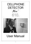
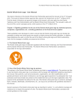
Cellphone
Detector Plus
610
User Manual
The EE Group Sales & Service
INTRODUCTION .............................................................. 3
QUICK START ................................................................. 3
FEATURES AND CONTROLS ......................................... 4
HOW TO USE IT .............................................................. 8
INSTALLATION ............................................................. 10
MAINTENANCE ............................................................. 11
DETECTION RANGE ..................................................... 11
CHANGING THE VOICE MESSAGE .............................. 12
TROUBLESHOOTING.................................................... 13
SUPPORT ...................................................................... 13
SPECIFICATIONS.......................................................... 14
FOR SERVICE OR SALES CALL:
THE EE GROUP/ ENTERPRISE ELECTRONICS
22826 MARIPOSA AVENUE
TORRANCE, CA 90502 USA
PHONE: 310.534.4456
FAX: 310.534.1233
EMAIL: [email protected]
2
INTRODUCTION
Your Cellphone Detector Plus™ 610 is a versatile state-of-the-art
cellular phone detector. It senses the radio frequency (RF)
transmissions from nearby cellular or mobile phones. If required, other
sources of RF transmissions can also be detected including two-way
radios, and other wireless communication devices. When a transmission
is detected, an alarm sequence begins that may include any
combination of visual LED flash, beeps and voice alert message
requesting users to turn off their communication devices. In addition the
unit can be used as a static or portable detector, and it can be used to
generate remote alarms, activate other equipment (including remote
indication devices) and extend alarm messages into other areas.
QUICK START
1) Attach AC power cord to the 9Vdc power socket on the underside of
the unit OR unscrew the REAR CASE SECTION to insert 4 C type
Alkaline batteries. Ensure polarity is correct. Then reattach the case.
2) Use both hands to remove the FRONT GRILLE PANEL (below left).
3) With a small flat screw driver gently check that the THRESH dial is
set to FAR (above centre). Caution: do not force this dial.
4) Locate the ON / OFF switch and click it to ON (above right).
5) Press the TEST / MUTE / REC button on the front of your Cellphone
Detector Plus™ 610 to test the alarm sequence.
6) Replace the front Grille Panel by gently sliding it back on until it snaps
into place.
Your Cellphone Detector Plus™ 610 is now operational. Test
your unit by making a call on your cellphone at various distances.
3
FEATURES AND CONTROLS
REAR CASE SECTION is used to cover the battery
compartment and also to facilitate wall fixing. To
access the battery compartment locate the four
back cover screws and remove them.
BATTERIES (‘4 off C’ type alkaline batteries - not
included). To install batteries please ensure they
are fitted according to the polarity diagrams in the
battery case. Then re-secure the back cover. Turn
the power switch to ON. Verify that the unit is
working normally by pressing the TEST/MUTE
button. The alarm should sound. Low battery
alert: Green LED will flash every 40 seconds rather
than every 10 seconds, and a buzzer will sound
every 6 minutes. When an external DC source is
used, batteries could still be installed for
emergency back up. If the external power fails or is
removed, the Cellphone Detector Plus™
automatically switches over to battery power.
Caution: damage can result to the battery container
if the unit is dropped with batteries fitted. Avoid
shipping or posting the unit with batteries installed.
TERMINAL BLOCKS (located approximately lower
mid-right PCB). These are permanent discreet
connection alternatives to the external sockets
located on the base of the unit.
Terminal block identification:
Pin 1(top) = Alarm Out; Pin 2 = 0V for Alarm Out
and Audio Out; Pin 3 = Audio Out; Pin 4 = external
9V DC power input; Pin 5 = external 0V power
input.
POWER is a green LED will blink on every 10
seconds to indicate that the unit is switched on and
is powered by batteries. It will blink on every 40
seconds when unit is switched on and powered by
batteries that need to be replaced. It will be
illuminated but blink off every 10 seconds when
connected to DC power.
ALERT is a very bright red LED that can be
switched to flash as a visual signal (Dipswitch # 3
UP). It can be switched to flash together with the
audio alert or as a silent visual alarm only. It can be
disabled if a visual alarm is not required signal
(Dipswitch # 3 DOWN)
4
TEST / MUTE is pressed to test the alarm.
While the alarm is playing, use a small screwdriver
to adjust the VOL (see below) CONTROL to the
desired volume level. MUTE MODE: If the alarm
has been sounding for more than 90 seconds, or if
The TEST / MUTE button is pressed during
an alarm, the Cellphone Detector Plus™
automatically enters a mute mode in which the
audio is silenced and the only indication of an alarm
is the front panel flashing light (if enabled) and the
ALARM OUT signal. The mute mode lasts for about
90 seconds but can be cancelled by pressing the
TEST/MUTE button again. It is also
labelled REC because it needs to be pressed when
the dealer changes the voice message (see p12
below).
DC INPUT: mains adaptors are available as an
optional extra and this will marginally improve
detection range and speaker volume. Many users
however prefer the benefit of wireless battery
installation.
USB PORT: a major difference between the 610
and previous versions is that this model uses a
software-based detection system. The
manufacturers intend to make available periodic
upgrades to improve functionality and performance,
which users can upload from their PC.
AUDIO OUT: external amplifiers or headphones
are connected to this socket. The Audio Output can
be used to input the alarm directly into a public
address system, extend the alarm so that it can be
heard from several locations, or amplify the audio
for excessively noisy areas. When the audio jack is
in use, the audio message can still play through the
unit’s speaker. The internal VOL control, however,
has no effect on audio out.
5
ALARM OUT: this socket will transmit an electronic
signal to a remote monitoring station. For example,
this output could be wired back to a security office,
nurse’s station, control room, or trigger an external
alarm system. The Alarm Output is an open
collector transistor. When no alarm is in progress
the output impedance is very high. When an alarm
is activated, the output goes into a low impedance
state of 66 ohms. Even if the RF signal has
terminated prior to the end of the alarm message,
the Alarm Output stays in the low impedance state
for the entire length of the alarm message. At the
end of the message the Cellphone Detector Plus™
checks to see if an RF signal is still present. If no
RF signal is present the alarm output returns to the
high impedance state. This allows the alarm output
to be used, as a trigger to count the number of
times RF has been detected as well as an indicator
for the length of time the alarm has been active.
AUDIO IN: this analog port allows the dealer
to upload a new voice message (see p12 below).
FRONT GRILLE PANEL is removed to locate the
internal controls and the audio speaker. Grasp this
panel on both sides and gently but firmly pulling it
upwards. Once all adjustments to the controls have
been made, replace the front Grille Panel by gently
sliding it back on until it snaps in to place.
Care should be taken not to prod the material
covering the speaker as this may result in damage
ON / OFF switch is located immediately below the
bank of 8 dipswitches. Move the ON/OFF switch to
the ON position. The Cellphone Detector Plus™
lights or winks the green Power LED depending on
whether the unit is operating from DC power or
batteries.
6
THRESH / VOL are a pair of dials that can be
adjusted with a small flat screwdriver. THRESH is
the sensitivity control which adjusts the range of
detection (see Detection Range p11). VOL adjusts
the speaker sound volume.
Turn these dials clockwise to increase. Do not force
the dial further than it can go. Within 1km of a
cellular base station the THRESH dial should be
set to max for most applications.
The bank of 8 dipswitches controls much of the
functionality of your Cellphone Detector Plus™.
These switches are numbered 1 to 8. On all of
them, UP is on, DOWN is off.
Descriptions of these dipswitches now follow.
1. VOICE
If VOICE is in the UP position, the audio alarm will
be a series of beeps followed by a voice message.
In the DOWN position the alarm consists of beeps
only
2. SPEAKER
If SPEAKER is in the DOWN position, the audio
alarm to the speaker within the unit is silenced.
However, the bottom panel AUDIO-OUT jack will
still function.
The speaker is silenced in some situations where
discretion is required for covert detection i.e.
concealing a unit below a desk with only flash alert
active, or by using headphones or connecting to a
remote speaker or alarm.
3. FLASH
If FLASH is in the DOWN position the red ALERT
Light will not flash during an alarm.
The flash alert is ideally disabled to save battery
power when it is necessary to install the Cellphone
Detector Plus™ in say a false ceiling or wall
compartment, away from view.
7
4. REGISTER
If REGISTER is in the UP position, in addition to its
normal operation, the Cellphone Detector Plus™
will recognize and sound the alarm on short
duration transmissions it detects such as cellular
telephone registration or standby signals and SMS
messages. These include the very short
transmissions phones make when they are
switched on.
Battery life will be considerably reduced if this
mode is activated, and it is recommended that DC
power be used.
5. PMR
If PMR is in the DOWN position, 2 way radio and
other non-cellular transmissions will not be
detected.
6. LINE / MIC
When the user is recording a new voice message
by way of an external microphone (not included),
this switch would be in the UP position. For other
sources (e.g. PC sound card) it should be placed in
the DOWN position. Switch #7 must also be ON to
enable recording.
7. RECORD
When the dealer is recording a new voice message
this switch will be in use. Do not activate it as the
normal use of the unit is deactivated and
that detection is suspended and Record mode is
active. For normal usage it should be placed in the
DOWN position.
8. FUNC
The last switch is disabled and reserved for future
variants.
HOW TO USE IT
The following offers some idea as to how the versatile Cellphone
Detector Plus™ can be used in certain organizations. In all cases field
tests should be conducted initially to determine the correct settings and
sensitivities.
8
Military bases: in government buildings and military bases the unit
should be installed in all sensitive areas. In addition to potential RAT
phones, the Cellphone Detector Plus™ can detect bugs emitting RF
within the specified band range. In addition, it can be rigged to trigger a
digital camera to capture an image of a person using a phone in a
restricted area by sending a signal to an external trigger mechanism
from the remote alarm terminal.
Prisons: Cellphone Detector Plus™ may be placed outside cell doors
during ‘lock up’ hours with silent LED flash alert only, 10 or 20 pieces at
a time at random or systematic sequence within prison wings to reduce
illicit cellular phone activity. In addition, Cellphone Detector Plus™ may
be installed in entranceways, corridors, waiting and meeting areas
where inmates’ visits are conducted as an audiovisual deterrent to
mobile phone users, and as a means of alerting staff. Voice message
used should naturally be firm and authoritative. PMR will be toggled
OFF to prevent false alerts being triggered by prison staff 2 way radios.
Hospitals: Cellphone Detector Plus™ units are installed in general
locations in corridors and waiting rooms to deter nuisance public cellular
phone usage. Sensitive electronic equipment within intensive care
wards and operating theatres that are vulnerable to RF interference will
have units installed near them with PMR toggled ON so that additional
non-cellular signals can be detected.
Schools and colleges: Cellphone Detector Plus™ units are installed in
general locations in corridors, assembly points, concourses, classrooms
and lecture theatres to promote conformity and establishment order.
Units are deployed in examination rooms to deter examination fraud via
text messaging.
Places of worship: Cellphone Detector Plus™ units are installed as a
deterrent at the main entrance with audio warning on low volume.
Where cellular phone misuse is a severe or persistent problem then
units can be installed in the main prayer area with audio alert set to low
volume. Voice message used should be cordial. In addition, the
Cellphone Detector Plus ™ can trigger an illuminated sign as a silent
deterrent in the main prayer area.
Museums and libraries: Cellphone Detector Plus™ units are installed
in all areas with audio warning on low volume. Voice message used
9
should be cordial to remind visitors to conduct themselves with
consideration.
Courtrooms: Cellphone Detector Plus™ units are installed directly
outside courtrooms with range set to near. LED flash, beeps and voice
warning with volume set to medium as an overt reminder of
establishment policy. Inside the courtroom itself, a wall-mounted unit
silently flashing in the public gallery may alert security staff.
Counter-Surveillance: consider covert detection with a concealed
Cellphone Detector Plus™ connected to a remote alarm. In some
cases, a unit working normally, giving overt audio / visual alerts may be
appropriate in a conference setting where people present are likely to be
trustworthy but forgetful.
Employee toilets and restrooms: consider invisible Cellphone
Detector Plus ™ units installed above false ceilings with LED flash
disabled and voice alert volume set to maximum. The element of
surprise this creates is a highly effective deterrent that will reduce time
wasting within organizations and workplaces.
In general: cellular phone detection and deterrence is an additional
layer of security for your organization. How effective this layer of
security will be will be dependant on the environment, the number of
devices installed and how the detectors are integrated with other layers
of security such as metal detection and access control systems.
Confidential advice and assistance regarding how this product can be
used is available from your supplier.
INSTALLATION
Your Cellphone Detector Plus™ may be used free standing on a shelf or
table, carried in a shoulder bag for portable use (i.e. with headphones
attached to the Audio Out socket), or fixed to a wall. The following is
relevant to a fixed installation: If the unit is to be battery operated or
battery backed-up AC power, prior to putting the unit into service, install
the batteries first. To make the unit easily visible to room occupants,
place it above 2 meters from floor level. This will also help avoid
unwanted impacts to the unit. For some applications it is desirable for
the Cellphone Detector Plus™ to be as unobtrusive as possible. If this
applies to your application, then it may also be desirable to turn off the
Flashing LED on the front of the unit and use the remote Alarm Output.
10
Mount the Cellphone Detector Plus™ on any non-metallic surface or
place it upright on a shelf or similar structure. Mounting the unit on or
very near metal surfaces can significantly reduce the coverage area.
Use 1-inch (2.54 cm) long, #6 (3.5 mm) dome head screws (not
included). Be sure the screws being used are appropriate for the
mounting surface.
MAINTENANCE
Your Cellphone Detector Plus™ requires little or no maintenance once it
has been installed except altering the settings as and when required or
to change batteries when they are running low. In addition, batteries
should be replaced within 12 months regardless of remaining power, to
reduce risk of damage due to possible battery leakage. Batteries should
be disposed of in accordance with local laws. The unit should be
periodically dusted with a dry cloth or duster.
DETECTION RANGE
Typically this will be an average of 10 metres (about 30 ft.) but it could be
as low as 1m (about 3 ft.) or as much as 30m (about 90 ft.) depending on
a combination of the following factors:
Variables within the control of the user:
1) Position of the THRESH adjustment dial.
2) The location of installation. For instance, intervening building work
such as a pillar can prevent a signal from being detected. As previously
mentioned, mounting near or on a metallic surface can also reduce
detection effectiveness.
3) The Cellphone Detector Plus™ is designed to work well with batteries
for a considerable period of time. Nevertheless you will achieve
marginally better detection capability and alarm output volume if the unit
is operated with an AC adaptor (available as an option).
Variables beyond the control of the user:
4) Distance to cellular base station is the most important environmental
factor. Generally, the nearer a cellular phone is to a base station or
transmitting tower, the weaker will be the signal that needs to come from
the phone.
11
5) Detection range is generally longer indoors than outdoors. This is
because mobile phones usually produce stronger signals inside a
building.
6) Characteristics of the cellular signal being detected are an important
factor. Some signals are easier to detect than others and the art is
getting the right balance. For example, GSM will be easier to detect than
CDMA. A phone call being initiated will be easier to detect than an
existing ‘walk-in’ conversation or an SMS message.
Tip: If you are within 1 or 2 km (about 1 mile) of a cellular base station,
for most applications the THRESH dial should be set to maximum.
CHANGING THE VOICE MESSAGE
Your Cellphone Detector Plus™ has a voice alert message already
installed by the manufacturer supplier. If required you can have your
dealer replace this message with one of your own choosing. This may
be in the form of speech captured in a PC .wav file format or text print
message delivered to the dealer and having the change made prior to
your taking delivery of the product.
For further information please contact:
Enterprise Electronics
22826 Mariposa Ave.
Torrance, CA 90502 USA
Phone: 310-534-4456
TO ADD REMOTE NOTIFICATION EQUIPMENT:
Order the Cell Detect Remote Alarm Indicator and specify how many persons
need to be made aware of the detector(s) that have been triggered.
When several detectors are utilized and a central station dispatch type of
manned or unmanned operation is employed, specify pagers as the silent
means of notifying as many persons as desired as to a detector breach.
Upon detection of unauthorized cell phone use, the detector silently triggers
the central controller, this unit in turn alerts a group of pagers silently with
a message 'Cell Phone Detected in East Hallway' type of alpha numeric
text message.
If it is desired to be notified by voice, then specify the VoiceAlert system and it
will key a base radio to alert via your 2-way radio system.
12
TROUBLESHOOTING
PROBLEM
LIKELY CAUSES
SOLUTION
The alarm is
not being
triggered by
nearby
cellular phone
activity:
Signal from phone is too weak,
this may be due to close
proximity of cellular base station;
The cellular phone may not
actually be transmitting; unit
may be mounted on a metal
surface or there is an
intervening structure which
blocks the signal; unit is not
powered up or batteries are not
installed correctly or have
insufficient power. The alarm
options may be switched off.
The record options may be
switched on.
Increase sensitivity THRESH to
maximum; Check the location of the
Cellphone Detector Plus™ and if
necessary move it to a non metallic
surface and away from intervening
architecture. Check power to the
unit and make sure the alarm
switches are toggled ON and
RECORD switch is toggled OFF. If
necessary, test the unit against other
phones and in other locations.
The alarm is
being
triggered all
the time,
even without
cellular
phones being
present.
Your device is being activated
by mobile phones outside of
your domain or it may be
activated by non-cellular RF
signals either inside or outside
your domain.
Switch PMR to off and / or reduce
THRESH.
Phones on
standby are
not triggering
The alarm.
The unit is
working OK
apart from
this.
Phone signals are periodic
(every few seconds or minutes)
and the RF burst is very short in
duration.
Ensure that the Register switch is
UP. However, just because a phone
is on standby, does not mean that it
is actually transmitting. Registration
signals can be seconds or minutes
apart. Even then, because of their
short duration they are more difficult
to detect.
WARRANTY:
The Cellphone Detector 610 Plus is warranted for one year from date of
purchase by the original purchaser and will be repaired or replaced at
no charge at the Distributor option when returned to the facory authorized
repair station postage paid. Should the user feel that the unit requires
service attention you are to contact the service station in advance of
shipment and receive a Return Material Authorization (RMA).
The telephone number to call for service is: 310-534-4456 from 8 AM to
5 PM M-F Pacific time (California).
13
SPECIFICATIONS
Dimensions
200 x 112 x 50mm.
Weight
0.4 kg.
Detection
Capability
900 GSM; 1800 GSM; EURO 3G; AMPS; CDMA; TDMA; PCS.
Typical
Detection
Range
0.5km from base station circa 10m (see Appendix).
Default
Voice Alert
Message
UK English Male.
Speaker
Volume
SPL with grille on and set to max volume. AC Adaptor: Beeps 82.4 dBA;
Voice 77.8 dBA; Battery: Beeps 79.4 dBA; Voice 74.1 dBA; 20 uPa with A
weighting filter at 1m.
Batteries
4 x "C" (not included).
Battery Life
12 months circa 10 alarms per day.
Low
Battery
Alert
Green LED flashes every 40 seconds rather than every 10 seconds as
normal. The buzzer will sound every 6 minutes.
Optional
External
Power
9V nominal 500mA DC supply, regulated or unregulated, range 8V to
13.5V. Connector is a long DC jack with 5.5mm outer diameter, 2.1mm
inner diameter. Inner is +ve. Outer is -ve.
Audio
Output
3.5mm mono jack, unbalanced signal approx 1V pk-pk (-10dB), signal to
tip, 0V to body.
Remote
Alarm
3.5mm mono jack, tip is signal output, ring is 0V. Signal is open collector
type: high impedance when not alarm, low impedance to 0V to signal
alarm. Maximum input voltage 24V, maximum sink current 50mA.
Audio Input
3.5mm mono or stereo jack
Terminal
Blocks
Pin 1(top) = Alarm Out; Pin 2 = 0V for Alarm Out and Audio Out; Pin 3 =
Audio Out; Pin 4 = external 9V DC power input; Pin 5 = external 0V power
input.
Operating
Temp
0–54°C.
Country of
Origin
United Kingdom distributed in the US by The EE Group (California)
14