1
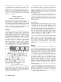
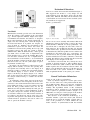
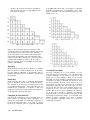
From: HCI-02 Proceedings. Copyright © 2002, AAAI (www.aaai.org). All rights reserved.
Constructing Human-Automation Interfaces:
A Formal Approach
Michael Heymann
Asaf Degani
Department of Computer Science
Technion, Israel Inst itute of Technology
[email protected]
Co mputational Sciences Division
NASA Ames Research Center, Cal ifornia
[email protected]
Abstract
In this paper we present a formal methodology and an
al gorithmic procedure for constructing human-automation interfaces and corresponding user-manuals.
Our focus is the information provided to the user about
the behavior of the underlying machine, rather than
the graphical and layout features of the interface itself.
Our approach involves a systematic reduction of the
behavioral model of the machine, as well as systematic
abstraction of information that displayed in the inter face. This reduction procedure satisfies two requirements: First, the interface must be correct so as not to
cause mode confusion that may lead the user to pe r form incorrect actions. Secondly, the interface must be
as simple as possible and not include any unnecessary
information. The algorithm for generating such inter faces can be automated, and a preliminary software
system for its implementation has be en developed.
Introduction
In many of today’s automated systems, humans are still
responsible for monitoring the behavior of the system.
Aircraft pilots, medical technicians, and engineers are
among the many users who interact with automated control systems to achieve specified operational tasks
(Parasuraman et al 2000). These may include (1) monitoring a machine’s mode changes during an auto-land,
(2) executing specific sequences of actions for settingup a medical radiation machine, and (3) preventing a
system from reaching unsafe states.
Automated control systems such as autopilots and
flight management systems exhibit extremely complex
behaviors. These are large systems that react to external
events, internal events, as well as user-initiated events.
For the user to be able to monitor the machine and interact with it to achieve a task, the information provided
to the user about the machine must, above all, be correct. In principle, correct interaction can always be
achieved by providing the user with the full detail of the
underlying machine behavior, but in reality the sheer
amount of such detail is generally impossible for the
user to absorb and comprehend. Therefore, the machine
interface and related user-manuals are always a reduced, or abstracted, description of the machine’s behavior. Naturally, we prefer interfaces that are simple
and straightforward. This reduces the size of user-
manuals, training costs, and perceptual and cognitive
burdens on the user.
In automated control systems such as autopilots and
other aircraft systems, the criteria for selecting the information that must be provided to the user (as well as information that can be abstracted away), are currently
based only on engineering and human-factors judgments.
The decisions are then evaluated in a series of laboratory
tests, expensive simulations, and flight-tests. When errors
are detected, costly changes must be made, and the system must be re-evaluated. Furthermore, the certification
process of proving that an interface design is safe and efficient places a heavy burden on manufacturers. For example, the new regulation and FAA Advisory Circular on
Flight Guidance Systems requires that the applicant
prove that the system is devoid of confusing modes and
related human-automation problems (Federal Aviation
Regulation 25.1329).
Despite the best efforts of engineers and hundreds of
hours of tests and simulations, interface errors may go
undetected because simulation and tests can never fully
examine all the possible modes and state combinations.
The operational community is well aware of the consequences of these errors: There are hundreds of narratives
in the Aviation Safety Reporting System (ASRS) database describing incidents in which pilots find themselves
confused and unsure what the machine is doing (ASRS
1998, Vakil et al 1995). There are also several airline
accidents in which inadequate interfaces were cited as a
contributing factor (ICOI 1992, NTSB 1997). In a recent
fuel-starvation incident that resulted in a dead-stick approach and landing by a commercial jetliner at Lajes
Field, Azores Islands, there are preliminary indications
that the fuel system interface may have been overly
complex and misleading (Aviation Week 2001).
In a recent paper (Degani et al 2002), we presented
an approach and methodology for verifying interfaces and
user-manuals. The methodology evaluates whether the interface and user-manual information are correct and free
of errors, given a description of the machine, the user’s
task, an interface, and a user-manual. The procedure can
be automated and used in the verification of complex
human-automation systems.
In this paper we take an additional step and discuss a
general approach for constructing correct and succinct interfaces. The algorithm presented here is suited for auto-
HCI-Aero 2002
119
mated machines that can be described as a system of
states. To illustrate the approach and algorithm, we use
a simplified version of a transmission system in a road
vehicle. Efforts are currently under way to apply the
methodology to a portion of the flight management system. A more detailed treatment of this topic can be
found in a recent NASA Technical Memorandum
(Heymann et al 2002).
Formal Aspects of
Human-Machine Interaction
In analyzing human automation interaction from a formal perspective, we consider four major elements: (1)
the behavior of the machine (its modes and states), (2)
the operational tasks (knowing which mode the machine
is in), (3) the interface (the mode annunciations), and
(4) the user’s model of the machine’s behavior (the information in the Aircraft Operating Manual).
Machine
Our focus in this paper is on automated machines that
can be described as a system of states. A state represents a mode, or a configuration, of the machine. The
machine transitions from one mode to another. Some of
the transitions are triggered by the user; for example,
the pilot switches from Flight Level Change to Vertical
NAVigation mode. Other transitions are automatic and
are triggered either by the machine’s internal dynamics
(e.g., timed transitions – if there is no pilot response
within 30 seconds, then the machine switches automatically to another mode), or by the external environment
(e.g., sensed transitions – if the outside temperature is
below 32 Fahrenheit, then the machines switches automatically to another mode).
Figure 1. Transmission system.
In the models described here, we always depict usertriggered transitions by solid arrows, while automatic
transitions are dashed. The transitions are labeled by
Greek symbols indicating the events under which the
machine moves from state to state.
120
HCI-Aero 2002
The machine in Figure 1 describes a simplified threespeed transmission system of a vehicle. The transmission
has eight states (representing internal torque-levels).
These are grouped into three speed modes: LOW ,
MEDIUM , and HIGH . States L1, L2, L3 are in the LOW
speed mode; M1, M2 in the MEDIUM speed mode; and
H1, H2, H3 in HIGH .
The transmission shifts up and down either automatically (based on throttle, engine, and speed values) or
manually (by pushing a lever). Manual up-shifts are denoted by event b and down-shifts by event r. Automatic
up-shifts are denoted by event d, and automatic downshifts by event g.
User’s Task
The second element of our framework is the user’s operational tasks, which in case of the transmission, consists
of tracking the three speed modes unambiguously. In
other words, the user must be able to determine the current mode of the machine and predict the next mode of
the machine. This requirement is akin to the type of questions pilots usually ask about automated cockpit systems
such as autopilots and flight management systems:
“What’s it doing now?” “What’s it going to do next?”
and “Why is it doing that?” (Wiener 2002).
We can describe the user’s task by partitioning the
machine’s state-set (the 8 internal states in Figure 1) into
distinct clusters, or modes. In the transmission system
there are three such clusters: LOW , MEDIUM and HIGH .
Note, however, that the user is required to track only the
modes and not every individual state of the machine
(e.g., transitions between states M1 and M2 inside
MEDIUM).
Interface
The interface commonly consists of two components: (1)
a control panel through which the user enters commands
and, (2) a display through which the machine presents information to the user about the status of the machine. The
status display shows, for example, the active mode, the
armed modes, as well as the events that take place.
As discussed earlier, the interface generally provides
the user with a simplified view of the machine. In almost
any display, especially those for automated systems,
many of the machine’s internal events and states are hidden from the user: Otherwise, the size of cockpit displays, for example, would be colossal. Hence the display
provides only partial information about the underlying
behavior of the machine. The cardinal issue, therefore, is
which information can be safely removed or abstracted,
and which must not.
Figure 2 describes the control panel and one proposed
display for the transmission system, where the user expects to be switching among the modes (LOW , MEDIUM
and HIGH ), by pushing up or down on the gear lever. Note
that in this display, all the internal states (e.g., L1, L2,
…to H3) are suppressed from view.
Evaluation Of Interfaces
Now let us evaluate the user-model described in Figure 3.
This suggested user model is a very simple one and
seems intuitively clear: The display shows only the three
modes (LOW , MEDIUM, and HIGH ). All the internal states
of the machine are removed and all the automatic (internal) transitions are suppressed.
Is this a good interface?
Figure 2. Display and control panel.
User Model
Manufacturers normally provide users with information
about the working of the machine in the user-manual
(e.g., Aircraft Operation Manual, Flight Crew Operations Manual) that describe the behavior of autopilots.
Most verbal statements in the Aircraft Operational example, have the following form: “when the autopilot is
in mode X and button ‘k’ is pushed, the autopilot engages in mode Y.” Similarly, the user-manual for the
transmission system tells the driver that when the
transmission is in LOW mode, pushing the lever up (and
triggering event b) will cause the system to shift to
MEDIUM mode. When in MEDIUM mode, a shift up will
give HIGH , and so on. This series of fragmented statements describe how to operate the machine. But again,
note that these statements are also a simplification of
the actual behavior of the machine; a lot of information
about the machine’s internal events has been omitted. If
this were not the case, the size (and weight) of operating manuals would be huge.
In practice, the user-manual is written based on the
display. This is naturally so because the operating manual explains and constantly refers to the display. It is
therefore possible to combine the user-manual information with the display to create a model, as shown in
Figure 3. In this way, the display (Figure 2) is “embedded” in the user-model, and we can prudently continue
the analysis without having to consider the interface
separately.
To summarize, what is being removed from the interface, user-manual, and consequently from the user’s
awareness is the automated internal transitions that take
place within each mode, or gear. For example, the LOW
mode has three possible internal states, L1, L2, L3.
When the user first up-shifts manually into LOW gear, L1
is the active state until a certain combination of throttle, engine, and speed is reached. At this point there is
an automatic transition to L2. This internal transition is
not evident to the driver-user, who is aware only of being in LOW . The question is how much of the internal information must be presented to the user in order to be
able to operate the machine correctly?
Figure 3. User model.
Figure 4. Alternate User model
Let us look at it more carefully. The manual shifts from
MEDIUM up to HIGH or down to LOW , as well as the downshift from HIGH to MEDIUM, are always predictable – the
user will be able to anticipate the next mode of the machine. However, the up-shift from the LOW gear depends
on the internal state: up-shifts from L1 and L2 transition
to MEDIUM mode, while the up-shift from L3 switches the
transmission to the HIGH mode. As a consequence, the
user will not be able to predict whether the up-shift will
lead the transmission from LOW to MEDIUM, or from LOW
to HIGH . We therefore must conclude that this user-model
(and display) are not adequate for the task.
An alternate user-model that may remedy the above
problem is depicted in Figure 4. This modified display
shows two LOW modes (LOW -1, LOW -2). The user-manual
further explains that the transitions between LOW -1 and
LOW -2 occur automatically. The user is told that upon upshift from LOW -1, the system transitions to MEDIUM,
while on upshift from LOW -2, the system goes to HIGH .
Formal Verification Of Interfaces
Again, we ask: is this a good interface?
Well, by intuitive inspection it seems quite reasonable—we have taken care of the problem with the manual up-shift from LOW . But let us apply the verification
methodology that was mentioned earlier to confirm it
formally. The algorithmic details of this verification
methodology and its application to an automated flight
control system are provided elsewhere (Degani et al
2002). Here, we will give a brief synopsis of the methodology in the context of the transmission example.
The objective of the verification methodology is to
determine whether a given user model (and interface)
enable the user to operate the machine correctly. The essence of the procedure is to check whether the user
model “marches” in synchronization with the machine
HCI-Aero 2002
121
model. This is determined by creating a composite
model of the user- and machine-models (see Figure 5).
We assert that a user-model is correct if there exist
no error states, no blocking states, and no augmenting
states in the composite model. An error state represents
a divergence between the machine and user-models.
That is, the interface tells the user that the machine is
in one mode when in fact the machine is in another. A
blocking state represents a situation in which the user
can in fact trigger a transition from one mode to another, yet this information is not provided to the user
(and when the transition happens, the user is surprised).
An augmenting state is a situation in which the user is
told that a certain mode change is possible, when in
fact it may be the case that the machine will not switch
into this mode or sub-mode.
Let us apply this methodology to verify whether the
alternative user-model of Figure 4 is correct. The machine (of Figure 1) starts in state L1 and the user-model
(of Figure 4) starts in LOW -1. So the first composite
state is “L1, LOW -1.” Upon an automatic up-shift transition (event d), the machine transitions to L2 and the
user model to LOW -2. Now we are in composite state
“L2, LOW -2.” Another automatic up-shift (event d) and
we are in “L3, LOW -2.” Now if the user pushes the up
shift-lever (event b) the machine transitions to H1 and
the user model also goes to HIGH , and everything is
okay. The user-model runs in complete synchronization
with the machine model.
Figure 5. Composite model of the alternative user model.
Recall that the user-model is aimed at enabling the operator to determine unambiguously which speed-mode
the transmission is in, or is about to enter. With this
mind, look at the following sequence: we start as before
in “L1, LOW -1”. Automatic up-shift (event d) takes
place and now we are in the composite state “L2, LOW 2.” The user now decides to use the manual up-shift
gear. The machine (according to Figure 1) will transition to state M1, yet according to the user-model of
Figure 4, we are now in HIGH mode. The new composite
state is “M1, HIGH .” This, of course, is a contradiction!
122
HCI-Aero 2002
The user thinks he is in HIGH mode where in fact the underlying machine is in MEDIUM (state M1). The resulting
ambiguity is a classical mode error (Norman 1983). W e
therefore must conclude that the user model of Figure 4
is also incorrect and work on finding another alternative.
It is of course possible to concoct other user-models
and then iteratively employ the verification procedure to
determine their correctness. However, such an effort is
not likely to be very efficient: it may take considerable
effort to develop and verify one design after another, with
no guarantee of success. Furthermore, even when a correct interface is identified, there is no assurance that it is
the simplest possible; there could be an equally good, or
even better abstraction, hiding just around the corner. The
development of a systematic approach for constructing
interfaces that are both correct and succinct is the subject of the next section.
Machine Model Reduction
As mentioned in the Introduction, one possible choice of
user-model is to display all the internal states of the machine. This will insure that there is never any problem in
predicting the next state of the machine. And therefore
there will never be an error state. But the display size
will be unimaginably large, the user manuals weigh tons,
and the human operator overwhelmed.
So our objective becomes clearer: to generate the
best possible user-models and interfaces that will allow
the operator to perform tasks safely. By best user models
and interfaces we mean ones that cannot be further reduced and simplified. To accomplish this, we take the
machine model of Figure 1 and reduce it systematically
with reference to the task requirements.
The proposed reduction procedure, which computes
all possible irreducible user-models, is a formal mathematical process that consists of several computational
steps. In the first step, compatible sets of internal states
are computed. These are sets of states that, in principle,
can be grouped together to form super states. These super-states have the property that individual state inside
them need not be distinguished by the user. The sets of
compatible states are successively enlarged until maximal compatible sets are obtained that cannot be further
enlarged.
The second computational step consists of selecting a
suitable subset of the set of maximal compatibles that
can form a state set of a reduced model. This selection
process is generally not unique, and there may be more
than one choice. Each choice will yield a different usermodel and interface. The ultimate choice must be based
on engineering and human-factors considerations of the
designers. Finally, the last step consists of constructing
the abstracted user-model and interface (that are associated with a particular choice).
In the next sub-sections we shall describe in some detail how the computation of reducing the machine model
is carried out. We re-emphasize that the computation is
formal and rather technical. The reader who is not inter-
ested in learning the detailed computational steps, may
wish (at least on first reading) to skip to the next section and see the results of the formal computation and
how the new user-model (and interface) are constructed.
Compatible States
We mentioned earlier that the user-model must enable
us to operate the system correctly with respect to the
user’s task(s). In our example, the user-model must allow the operator to track the machine as it switches
from one mode to another. But we have already learned
there is no requirement that the user track every internal
state of the machine. There is no need for us to distinguish between two internal states (say M1 and M2 of
mode MEDIUM ), if, after following any given event sequence, we end up in the same mode (e.g., HIGH ,
MEDIUM or LOW ), regardless of which of the two states
we started in. If that’s the case, we say that the two
states (M1 and M2) are compatible. Two compatible
states can be grouped together in the abstracted model-there is no need to distinguish between M1 and M2 in
the interface.
Trying to find state pairs that are compatible is difficult, instead let’s turn our attention to state-pairs that
are incompatible. If we can compute all incompatible
pairs (that cannot be grouped together), the remaining
pairs must be compatible. Incompatible pairs are, for
example, two states that belong to two distinct modes.
Thus, the state-pair L1 and H3 is incompatible: L1 belongs to mode LOW and H3 belongs to mode HIGH . W e
must never group them together on the display; for otherwise we create an error-state. Another reason for
deeming a pair of states incompatible is if a transition
out of one of the states and the same transition out of
the other, lead us, respectively to two states of a pair
that was already deemed incompatible.
Identifying Compatible Pairs
Now we proceed to identify all the compatible (and incompatible) pairs in the machine model. Once we identify compatibles, we can group them together, abstract
them, and ultimately reduce the display complexity.
See (Kohavi 1978, Paull et al 1959) where related
model reduction procedures are discussed.
Using the above observations regarding compatible
and incompatible pairs, we proceed as follows to create
the initial resolution.
1. For each state pair (e.g., L1 and H3) that can be
immediately determined as incompatible (because
they belong to two distinct modes – LOW and
HIGH ), we mark the corresponding cell I (for Incompatible).
2. For all other state-pairs, we write in their cells the
next transition pair. For example, for the state pair
(M1,M2) the next transition pair, after initiating the
common event b, is (H1,H2).
Figure 6. Initial resolution.
Initial Resolution
Figure 6 shows a table of all possible state-pairs for the
transmission system (there are 28 such pairs), as well as
the initial resolution. To explain how we get this initial
resolution let’s start at the top (the machine model is
provided so that the reader can follow the process): The
state pair (L1, L2), transitioned on automatic up-shift d
to the pair (L2, L3). And that’s what we write inside the
top cell. The state pair (L1, L3) transitions into (M1,H1)
on manual up-shift b. However, from (L2, L3) there are
two possible transitions: automatic down-shift g takes us
to (L1,L2), and manual up-shift b takes us to (M1,H1).
So we place these two transition pairs in the cell of L2
and L3. (M1,M2) takes us to (H1, H2) on manual up-shift
b (in the table we write the triggering event as a subscript for the reader’s convenience). And so on. Notice,
however, that the cell H1,H3 is empty. This is because it
is neither incompatible nor it has associated transition
pairs.
Second Step
We now continue with the reduction process. But from
this step onward, we do not need to refer to the machine
model anymore. We simply start substituting values in
the cells according to the following procedure:
1. Cells that are incompatible stay that way (I). Every
cell that has not yet been determined as I in Figure
6 (e.g., L1,L3) is updated as follows: If a cell includes a transition pair (e.g., M1,H1) that has already been determined to be incompatible (I), then
the harboring cell is also denoted I (see Figure 7).
2. Otherwise, the cell is modified as follows: Each transition pair in the cell is replaced by all the transition
pairs that appeared in their original cell. For example, the cell of (L1,L2) contains the transition pair
HCI-Aero 2002
123
(L2,L3)b. We look into cell (L2,L3) and find in
there the state-pairs (L2,L3)g and (M1,H1)b. We
place them in (L1,L2).
et al. 2002). This means that a state triple is compatible
if its three constituent pairs are compatible, a state quadruple is compatible is its four constituent triples are compatible, and so on.
Figure 8. Third reduction step.
Figure 7. Second reduction step.
Figure 7 shows the table after the completion of the
second step. First, we replaced the transition pairs in the
cell (L1,L2) by those in the cell (L2,L3). The cells
(L1,L3) and (L2,L3) were denoted as I because their
cells include incompatible pairs. The remaining undecided state pairs (those that have not yet been given the
value I) were modified according to the above procedure. For example, in the cell (M1,M2) we placed the
transition pair (H2,H3)d.
Third Step
In the third step the table shown in Figure 8 is obtained.
Here cell (L1,L2) is marked I because one of the transition pair inside it--(M1,H1)b--is incompatible. The remaining undecided cells are modified as specified by
the procedure.
Fourth Step
In this step we realize that no additional incompatible
pairs are identified, and the table remains identical to
that of Figure 8. At this point, no further iterations will
ever produce an I. Therefore, all the undecided cells are
marked C (for compatible) as in Figure 9. This concludes the resolution procedure and the determination of
all incompatible and compatible pairs.
Computing all Compatible Sets
Following the computation of all compatible pairs, we
must compute all compatible triples, quadruples, etc.,
until no new compatibles are found. The computation is
based on the observation that a set of states is compatible if all its constituent pairs are compatible (Heymann
124
HCI-Aero 2002
Figure 9. Completed reduction table.
Creating the User-Model
Not every compatible set is a good candidate of a succinct user model. If a compatible set is contained within
a bigger compatible set, we might as well choose the
bigger one as a better candidate. Thus, we are actually
interested only in the maximal compatibles that are not
contained in any bigger compatible set. In general, there
are many maximals. To create a base state-set for a reduced model, we must choose from the set of maximal
compatibles judiciously. We must insure that our selection is such that each state of the machine model is represented in at least one of the selected maximal compatibles. But we do not want redundancy. In particular,
we do not want to be able to eliminate any maximal
compatible from our selection without destroying the full
representation requirement. Such a set of maximal compatibles is called a minimal cover. Thus, a minimal
cover of maximal compatibles, forms a set of states for
an efficient user-model.
Constructing the Interface
References
Figure 9 shows that the compatible pairs (C) consists of
the two internal states in MEDIUM mode (M1,M2) as
well as all the possible state-pairs in HIGH ((H1,H2),
(H1,H3), and (H2,H3)). The results tell us that we do
not need to display the two internals states in MEDIUM,
and none of the three internal states in HIGH . And what
about LOW mode? Since L1, L2 and L3 do not appear in
any compatible pairs, we have no choice but to display
them to the user. Figure 10 is our best (i.e., minimal)
user-model possible for the machine of Figure 1.
Aviation Safety Reporting System. 1998. FMC altitude
capture function reports. Search Request No. 5183. Mountain View, CA: Battelle Memorial Institute.
Aviation Week and Space Technology. 2001. Airbus A330 Fuel System: How It Works and Pilot Choices
(March 12, 2001), 34-37.
Degani, A., Shafto, M., and Kirlik, A. 1999. Modes in
Human-Machine Systems: Constructs, representation,
and classification. International Journal of Aviation Psychology, 9(2), 125-138.
Degani, A. and Heymann, M. 2002. Formal Verification
of Human-Automation Interaction. Human Factors.
Heymann M., and Degani A. 2002. On abstractions and
simplifications in the design of human-automation interfaces. NASA Technical Memorandum 2002-211397. Moffett Field, CA. (http://ic.arc.nasa.gov/publications/number
.html).
Indian Court of Inquiry. 1992. Report on accident to Indian Airlines Airbus A-320 aircraft VT-EPN at Bangalore
on 14th February, 1990. Indian Government.
Kohavi, Z. 1978. Switching and Finite Automata Theory.
New York: McGraw-Hill.
National Transportation Safety Board. 1997. Wheels-Up
Landing of Continental Airlines Flight 1943, Douglas
DC-9 N10556, Houston, Texas, on February 19, 1996.
(Report Number: AAR-97-01). Washington DC: NTSB.
Norman, D. A. 1983. Design rules based on analysis of
human error. Communications of the ACM, 26(4), 254258.
Parasuraman, R., Sheridan, T.B., and Wickens, C.D.
2000. A model for the types and levels of human interaction with automation. IEEE Transaction on Systems,
Man, and Cybernetics – Part A: Systems and Humans,
30(3), 286-297.
Paull, M.C. and Unger, S.H. 1959. Minimizing the number of states in incompletely specified sequential switching functions. Institute of Radio Engineers Transactions
on Electronic Computers, 356-367.
Vakil, S., Hansman, R. J., Midkiff, A. H., and Vaneck, T.
1995. Mode awareness in advanced autoflight systems. In
T. B. Sheridan (Ed.), Proceeding of the International
Federation of Automatic Control; Man-Machine Systems
(IFAC-MMS) Conference. Boston, MA: IFAC.
Wiener, E.L. 2002. Personal communication, April 5.
Woods, D., Sarter, N., and Billings, C. 1997. Automation
surprises. In G. Salvendy (Ed.), Handbook of human factors and ergonomics (1926-1943). New York: John Wiley.
Figure 10. The reduced user model.
Conclusions
The problem of incorrect and overly complex interfaces
has plagued the design of human-automation interaction, and still does. Such design problems are responsible, in part, for what has been termed “automation surprises” (Woods 1997). Such surprises occur when pilots
have difficulty understanding the current status of an
automatic system as well as the consequences of their
interactions with it (Degani et al 1999).
In this paper we have shown a methodology and an
algorithmic procedure for constructing user-models and
interfaces. We have focused on the information content
of the display and not on the graphical user interface.
Two objectives have guided us in developing the methodology: (1) that the interfaces and user-models be correct; (2) that they be as simple as possible.
This paper has presented the flavor of our approach
to constructing correct and succinct user interfaces, and
by use of the transmission example illustrated the iterative reduction process, which is at the heart of the
methodology. The reader is encouraged to refer to
(Heymann et al 2002) for more details.
The methodology presented here deals with discreteevent systems (those that have states and modes). However, the approach is general and therefore amenable to
other type of representations. It remains an interesting
topic of future research to expand this approach to systems that have both continuous and discrete events (hybrid systems) as well as timed systems. And indeed,
promising results in verification of a complex hybrid
system (an autoland system of a commercial airliner),
have already been obtained.
HCI-Aero 2002
125