1
Real-Time Cooperative Behavior for
Tactical Mobile Robot Teams
Final Report / A003
February 2001
Prepared by:
Georgia Tech College of Computing and
Georgia Tech Research Institute
Georgia Institute of Technology
Atlanta, Georgia 30332
Prepared for:
DARPA/ATO
3701 North Fairfax Drive
Arlington, VA 22203-1714
Contract No. DAAE07-98-C-L038
A UNIT OF THE UNIVERSITY SYSTEM OF GEORGIA
ATLANTA, GEORGIA 30332
Table of Contents
1.
2.
Technical Approach Summary................................................................................................ 1
System and Software Description ........................................................................................... 3
2.1
Executive Subsystem....................................................................................................... 5
2.1.1
MissionLab Console................................................................................................ 5
2.2
Premission Subsystem..................................................................................................... 6
2.2.1
Configuration Editor ............................................................................................... 6
2.2.2
Usability Data Logging ........................................................................................... 7
2.3
Runtime Subsystems (1 per robot) .................................................................................. 8
2.3.1
Reactive Behaviors.................................................................................................. 8
2.3.2
Hardware Drivers .................................................................................................... 8
2.3.3
Low-level Software ................................................................................................. 9
3. Summary of Demonstration Results...................................................................................... 10
3.1
Fort Sam Houston.......................................................................................................... 10
3.1.1
Building Approach ................................................................................................ 10
3.1.1.1 DGPS performance ........................................................................................... 11
3.1.1.2 Terrain and locomotion ..................................................................................... 11
3.1.1.3 Robot behaviors................................................................................................. 12
3.1.1.4 Miscellaneous data ............................................................................................ 12
3.1.2
Stair climbing ........................................................................................................ 13
3.1.3
Indoor assessment.................................................................................................. 13
3.1.3.1 Hardware Setup ................................................................................................. 13
3.1.3.2 Remote-Room-Inspection Task Construction ................................................... 14
3.1.3.3 Execution........................................................................................................... 15
3.2
Montgomery County Public Safety Training Academy ................................................ 16
3.2.1
Indoor Situational Awareness Mission.................................................................. 16
3.2.2
Outdoor DGPS Approach Mission........................................................................ 17
3.2.3
Additional Results and Lessons Learned .............................................................. 19
4. Skills Impact Study for Tactical Mobile Robot Operational Units ....................................... 21
4.1
Human-Robot Interface design...................................................................................... 22
4.1.1
Wearable Computing and Augmented Reality...................................................... 22
4.1.2
Input Device Technologies.................................................................................... 27
4.1.2.1 Pose Estimation Sensors ................................................................................... 27
4.1.2.1.1 Gloves.......................................................................................................... 28
4.1.2.1.2 Orientation Trackers.................................................................................... 31
4.1.2.1.3 Direct-contact devices ................................................................................. 32
4.1.2.1.4 External observation/tracking systems ........................................................ 35
4.1.2.2 Keyboards.......................................................................................................... 36
4.1.2.3 Speech Recognition........................................................................................... 38
4.1.2.4 Eye Trackers...................................................................................................... 40
4.1.2.5 Other.................................................................................................................. 40
4.1.3
Output Device Technologies ................................................................................. 42
4.1.3.1 Displays ............................................................................................................. 42
4.1.3.1.1 Head Mounted Displays .............................................................................. 43
i
4.1.3.1.2 Retinal Displays .......................................................................................... 46
4.1.3.1.3 Omnidirectional camera imagery ................................................................ 48
4.1.3.2 Audio................................................................................................................. 49
4.1.3.3 Tactile and Haptic devices ................................................................................ 49
4.1.3.3.1 Gloves for Haptic and Tactile Feedback ..................................................... 51
4.1.4
Support Technologies............................................................................................ 52
4.1.4.1 Cabling and Communication............................................................................. 52
4.1.4.2 CPUs ................................................................................................................. 52
4.1.5
Operator Interface Design and Integrated Augmented Reality.............................. 53
4.1.6
OCU System Design ............................................................................................. 56
4.2
Human Factors and TMR .............................................................................................. 59
4.2.1
Human Factors Introduction.................................................................................. 59
4.2.1.1 Organization of Control .................................................................................... 59
4.2.1.2 Telepresence and Cognition .............................................................................. 60
4.2.2
Sensory Feedback.................................................................................................. 61
4.2.2.1 Sensory Characteristics of Humans................................................................... 61
4.2.2.2 Vibratory Feedback ........................................................................................... 64
4.2.2.3 Haptic/Tactile Feedback.................................................................................... 64
4.2.2.4 Auditory feedback ............................................................................................. 66
4.2.2.5 Visual imagery .................................................................................................. 67
4.2.2.6 Improper Feedback: Motion Sickness .............................................................. 67
4.2.3
Operator Performance ........................................................................................... 68
4.2.3.1 Metrics............................................................................................................... 68
4.2.3.2 Operator Characteristics in Supervisory Control .............................................. 69
4.2.3.3 Monitoring Tasks .............................................................................................. 72
4.2.3.4 Driving/Navigation Performance ...................................................................... 73
4.2.4
Human Factors and Displays................................................................................. 75
4.2.4.1 Helmet Mounted Displays................................................................................. 75
4.2.4.2 Heads-up Displays............................................................................................. 75
4.2.4.3 Other Display considerations ............................................................................ 75
4.2.5
Mental Workload................................................................................................... 76
4.2.6
Human error .......................................................................................................... 79
4.2.6.1 Fatigue............................................................................................................... 80
4.2.6.2 Trust .................................................................................................................. 80
4.2.6.3 Vigilance Decrement......................................................................................... 81
4.2.6.4 Stress ................................................................................................................. 81
4.2.7
Human Factors in Design ...................................................................................... 82
4.2.7.1 Design Methodologies....................................................................................... 82
4.2.7.2 Display Design Considerations ......................................................................... 85
4.2.7.3 Task Analysis Models for Design ..................................................................... 86
4.2.7.4 Alarm Design .................................................................................................... 86
4.2.7.5 Teleoperator interface design ............................................................................ 87
4.2.8
Operator Selection................................................................................................. 88
4.2.8.1 Individual Differences ....................................................................................... 88
4.2.8.2 Skills needed ..................................................................................................... 89
ii
4.2.8.3 Tunnel Vision as basis for selection.................................................................. 91
4.2.9
Training operators ................................................................................................. 92
4.2.10
Cognitive Modeling............................................................................................... 93
4.2.11
Summary Recommendations – Human Factors .................................................... 94
5. Usability Study Results ......................................................................................................... 99
5.1
Introduction And Background....................................................................................... 99
5.2
MissionLab Explained................................................................................................. 100
5.2.1
CfgEdit – MissionLab Configuration Editor....................................................... 100
5.2.2
MLab – MissionLab Simulation and Execution Interface ................................. 101
5.3
Subject Demographics................................................................................................. 102
5.4
Study Procedure .......................................................................................................... 104
5.4.1
Phase 1................................................................................................................. 106
5.4.1.1 Tutorial 1-1...................................................................................................... 106
5.4.1.2 Tutorial 1-2...................................................................................................... 108
5.4.1.3 Task 1-1........................................................................................................... 110
5.4.1.4 Task 1-2........................................................................................................... 112
5.4.2
Phase 2................................................................................................................. 113
5.4.2.1 Tutorial 2-1...................................................................................................... 113
5.4.2.2 Tutorial 2-2...................................................................................................... 114
5.4.2.3 Task 2-1........................................................................................................... 116
5.4.2.4 Tutorial 2-3...................................................................................................... 118
5.4.2.5 Tutorial 2-4...................................................................................................... 119
5.4.2.6 Task 2-2........................................................................................................... 121
5.5
Evaluation.................................................................................................................... 122
5.5.1
Description of Data Extracted ............................................................................. 122
5.5.1.1 Phase 1............................................................................................................. 123
5.5.1.2 Phase 2............................................................................................................. 124
5.5.2
Description of Analysis ....................................................................................... 124
5.5.2.1 Phase 1............................................................................................................. 125
5.5.2.2 Phase 2............................................................................................................. 128
5.5.3
Discussion ........................................................................................................... 130
5.6
Alternative Interfaces (Additional Pilot Study)........................................................... 131
5.6.1
Task Analysis ...................................................................................................... 131
5.6.2
Requirements....................................................................................................... 132
5.6.2.1 Functional Requirements................................................................................. 132
5.6.2.2 Non-functional Requirements ......................................................................... 133
5.6.3
Three Key Aspects of the Design Space ............................................................. 134
5.6.4
Current and alternative interface designs ............................................................ 135
5.6.4.1 Current MissionLab Interface.......................................................................... 135
5.6.4.2 Interface Design A........................................................................................... 136
5.6.4.3 Interface Design B (not implemented yet) ...................................................... 137
5.6.4.4 Interface Design C (not implemented yet) ...................................................... 138
5.6.5
Prototype Evaluations.......................................................................................... 140
5.6.5.1 Evaluation Exercise 1 - Waypoint Creation .................................................... 140
5.6.5.1.1 Setup.......................................................................................................... 140
iii
5.6.5.1.2 Results ....................................................................................................... 140
5.6.5.1.2.1 Error Log and Video Capture ............................................................. 140
5.6.5.1.2.2 Think Aloud ....................................................................................... 141
5.6.5.1.2.3 Feedback............................................................................................. 141
5.6.5.2 Evaluation Exercise 2 - Mission Identification ............................................... 142
5.6.5.2.1 Setup.......................................................................................................... 143
5.6.5.2.1.1 Results ................................................................................................ 144
5.6.6
Discussion ........................................................................................................... 144
5.7
Usability Conclusions ................................................................................................. 145
6. References ........................................................................................................................... 147
Appendix A. Operator training................................................................................................ 157
Appendix B. Human Factors Considerations and Display Systems....................................... 209
Appendix C: Consent Form .................................................................................................... 221
Appendix D: Pre-test, background questionnaire.................................................................... 223
Appendix E: Post-test questionnaire/survey............................................................................ 229
Appendix F: Administrator Scripts ......................................................................................... 231
Appendix G: Sample Event Log File ...................................................................................... 256
Appendix H: Sample CDL File............................................................................................... 258
Appendix I: Mean and Standard Deviations for Data Analysis ............................................. 260
iv
1. TECHNICAL APPROACH SUMMARY
Our technical approach to achieving intelligent tactical behaviors for TMR robots is described in this section. We have specific technical approaches in three research areas:
•
Fault-tolerant multi-robot behaviors,
•
Mission specification and user interface, and
•
Real-time resource management.
(Originally, communication minimization was also a research topic, but was deleted early in
the program at government request.)
We envision that the nature of military operations in urban terrain (MOUT) can fundamentally change by empowering the personnel in these units with multiple mobile robot assets that
extend their ability to perceive and act within the battlefield without increasing their exposure. It
is insufficient merely to deploy these assets; they must be controlled and configured in a meaningful way by average soldiers. This is no mean feat, but if this vision is realized it can provide
significant force multiplication capabilities and extended reach within the battlespace (force projection). This must be accompanied by feedback and control methods that do not overload the
operator of the system and yet can provide uniform control of multiple advanced robotic systems
while simultaneously increasing the unit's overall situational awareness. The impact of this system will be manifested in several ways:
•
Reactive behavioral configurations for robot teams that support fault-tolerant operations typically found in the battlefield, to increase immunity against electronic countermeasures and individual agent failure.
•
Team teleautonomy providing command and control capabilities for entire groups or
subgroups of battlefield robots without producing cognitive overload on the operator.
•
The ability of a military operator to expand his influence in the battlespace, dynamically controlling in real-time his deployed robotic team assets in a context-sensitive
manner.
Throughout the program, our research focused on the generation of mission-specific designs
created specifically for TMR operations that can be readily tailored by an easily trained operator
for the situation at hand. These tools have been shown to be effective in the hands of students
and military personnel, through the use of visual programming, information hiding, and reusable
software components.
We have applied our expertise to develop the following innovative research results for tactical mobile robot teams:
1. A suite of new fault-tolerant reactive behaviors,
2. A reusable mission specification system including team communication protocols,
3. Sound and predictable real-time processing and communication,
4. Major demonstrations of usability and tactical effectiveness,
1
5. A skills assessment study for human-robot operator interfaces, and
6. A usability study based on experiments with human subjects.
2
2. SYSTEM AND SOFTWARE DESCRIPTION
Real-time
Specification
Communications
Expert
Configuration
Editor
MissionLab
Console
Hummer
Groundstation
User Data
Logging
Runtime Data
Logging
PREMISSION
EXECUTIVE
IPT
IPT
RUNTIME
Reactive
Behaviors
IPT
IPT
IPT
IPT
"Robot"
"Robot"
"Robot"
"Robot"
Hardware
Drivers
Low-level
Software
Robotic
Hardware
Figure 1: System Architecture
Figure 1 depicts the overall system architecture developed for this effort. It contains 3 major
subsystems: Executive, Premission, and Runtime. The executive subsystem is the major focus
for operator interaction. It provides an interface to both the runtime simulators and actual robot
controllers, as well as the premission specification facilities and the physical operator groundsta3
tion itself. The premission subsystem’s role is to provide an easy-to-use interface for designing
robot missions and a means for evaluating overall usability. The runtime control system, which is
located on each active robot, provides the execution framework for enacting reactive behaviors,
acquiring sensor data and reporting back to the executive subsystem to provide situational
awareness to the team commander. Additionally, a separate support system is provided for interprocess communications.
In Figure 1, typical communication paths between components are shown. Wherever separate threads of execution exist, this communication is implemented with IPT, to be described
later. In other cases, communication may take the form of dedicated point-to-point links or conventional parameter-passing during the invocation of processes.
The figure shows a “robot” as the combination of reactive behaviors, appropriate hardware
drivers, both actuator-specific and sensor-specific low-level software, and the robot hardware
itself. This assemblage of components provides a uniform, hardware-independent interface to
the executive subsystem which is equally suitable for simulated robots. The runtime system consists of one or more instances of these assemblages, with four shown in this particular case.
Figure 2: MissionLab Console (mlab).
4
2.1 Executive Subsystem
The executive subsystem consists of the MissionLab console, faster-than-real-time simulator, and runtime data logging components.
2.1.1 MissionLab Console
The MissionLab console (mlab) (Figure 2) serves as the central interface for the execution of
a mission. The mlab program presents results of either simulations or actual robotic missions directly to the operator. It requires the use of the interprocess communications subsystem (IPT),
described below, to maintain contact with the robots and other active processes. The MissionLab
console provides the following capabilities:
•
Loads precompiled robot control programs and overlay description files
•
Configures the display
-
generating obstacles for simulations
-
altering the scale of the display
-
changing the virtual time for simulations
-
scaling the size of the display (zooming)
•
Provides a Command interface that permits interactive step-by-step command issuance
by the operator using CMDL, a structured English language
-
has the ability to execute, stop, pause, restart, rewind, single step, and abort missions
during execution
-
has the ability to use team teleautonomy by directing robots to particular regions of interest or by altering their societal personality.
•
Provides display options
-
leave trails where the robots have been
-
highlight obstacles that affect the robot
-
show instantaneous directional reaction of robot to its environment
The MissionLab console also provides a display (Figure 3) that shows either:
1) The output of a simulated robotic mission that is run faster than real-time and can serve
to determine whether or not a premission specification has been successfully completed.
2) An operator mission display screen where robots in the field report back their position
and relevant mission data that is shown on the mlab display to provide situational awareness and context for higher level decisions regarding aborting, continuing, or biasing the
mission in various ways.
5
Figure 3: Display during execution of simulated mission (display of actual robot mission is
similar).
2.2 Premission Subsystem
The premission subsystem involves the specification, creation, and construction of behaviorbased robots suitable for specific missions. It provides a user-friendly graphical programming
environment and a series of language compilers used to transform the high-level iconic description into executable code suitable for the executive subsystem. In addition, it provides data logging tools that are geared for usability studies leading to the enhancement of the user interface.
2.2.1 Configuration Editor
The configuration editor (cfgedit) provides a visual programming entry point into the system
(Figure 4). It is geared to average end-users and requires limited training to use. The interactive
iconic interface generates configuration description language (CDL) code which, when compiled
and bound to a particular architecture and robots, generates a meta-language. In this project this
is CNL, the configuration network language, that serves as a precursor to the C++ code that is
ultimately generated when the CNL code is compiled. This resulting C++ code forms the executable code for the robot controller itself. Within the executive subsystem, this code is then directed either to the simulation or the actual robots for execution.
6
Figure 4: Graphical configuration using cfgedit.
2.2.2 Usability Data Logging
Additional software is used to record user actions during premission planning. This includes data such as the number and type of keystrokes and mouse clicks, time to create certain objects, and other relevant data. These data are then used to interpret the skill by
which a user is capable of achieving within the system, and after subsequent usability
analysis, is used to refine the design interface itself. It is a support tool geared for formal
usability studies (
Figure 5).
7
Figure 5: Usability Laboratory.
2.3 Runtime Subsystems (1 per robot)
The runtime control code created by the premission subsystem and then tested in simulation
within the executive subsystem is then sent to the actual robotic systems for execution. Thus
there is one runtime subsystem located on each robot required for the mission. IPT provides interprocess communication between the robots and the mlab console.
The runtime system consists of a set of reactive behaviors and sensor strategies to interpret
and react to the world; hardware drivers customized to interface designated robots to the MissionLab system; low-level robot control code generally provided by the robot manufacturer; and
the actual robotic and sensor hardware.
2.3.1 Reactive Behaviors
A collection of reactive behaviors is compiled and downloaded to each robot for execution
of the mission. These reactive behaviors embody the mission specification designed within cfgedit. They process sensor data as rapidly as possible and issue commands to the lower level software for timely execution on the robot. These behaviors include activities such as obstacle avoidance, waypoint following, moving towards goals, avoiding enemies, and seeking hiding places,
all cast into mission-specific reusable assemblages. Action-oriented perceptual code supports
both Newton Labs Cognachrome real-time color vision systems, laser rangefinders, infrared
proximity sensors, DGPS, and ultrasonic data. Team behaviors, such as team teleautonomy, formation maintenance, and bounding overwatch are also bundled for execution as necessary. The
output of these behaviors is sent to the groundstation for monitoring purposes as well as to the
robot for execution.
2.3.2 Hardware Drivers
In order for MissionLab to be able to build an executable program to run on a given robot, it
requires an ensemble of routines to set up, control, and receive feedback from the actual (or
simulated) robot. Some variation in capabilities occurs among the various robots that are supported, but the typical routines for the TMR platforms (Pioneer AT and DARPA Urban Robot)
include movement commands, range measurement commands, position feedback commands,
system monitoring commands, and initialization/termination commands.
8
Additional drivers are required for sensors which are not tightly integrated into the onboard
robot control system (see PSOS and ARC below). These include such vision-related capabilities
as specifying the characteristics of a target and requesting target tracking status (and position, if
available).
2.3.3 Low-level Software
Low-level software includes embedded software and firmware that is typically provided by
the vendors of robots and sensors in order to access the basic capabilities of those devices. For
this project, this classification includes PSOS (running on the Pioneer AT robot controller), Mobility and rFlex (running on the Urban Robot controller), and ARC (running on the vision system).
The onboard microcontroller of the Pioneer robot is equipped with the Pioneer Server Operating System (PSOS) software. PSOS serves the serial communication port provided for the receipt of commands and the return of status information. As such, most of the functions listed in
the previous section for the robot driver result in the transmission of a message to PSOS, which
in turn handles the request.
The Cognachrome vision system behaves similarly, with its serial port served by an embedded operating system called ARC. This multitasking system allows the vision tracking parameters to be changed and issues tracking results at specified intervals. ARC provides a C development environment and runtime system for the generation and support of vision programs that exceed the basic capabilities provided with the Cognachrome system.
The onboard controller of the Urban Robot is a PC-compatible computer running the Linux
operating system. It runs a CORBA server which handles requests for hardware operations, including both sensing and locomotion. These requests can originate from other processes running
on the same controller or through a networked connection. Both wired and wireless Ethernet
connections are possible.
9
3. SUMMARY OF DEMONSTRATION RESULTS
In addition to numerous experiments performed on a regular basis, and a few onsite demonstrations for TMR personnel, two major demonstrations were performed. One of these was at
Fort Sam Houston in 2000, and the other was at the Montgomery County Public Safety Training
Academy in 2001. Both demonstrations required at least one earlier site visit for familiarization
and experimentation.
3.1 Fort Sam Houston
The primary thrust of our experiments at Ft. Sam Houston was to assess the status and reliability of our intermediate demonstrations that will eventually evolve into an end-to-end demonstration of the hospital assessment scenario. These experiments were divided into three parts,
corresponding to the three phases of the demonstration:
Building approach – assess the Pioneer and DGPS as suitable technologies in conjunction
with the MissionLab system as the waypoint planner and behavior scheduler.
Stair climbing – we expected not to have any experiments in this area, having only received
the Urban Robot platform from the TMR pool a few weeks earlier. But since we had already developed a basic MissionLab interface, we were able to at least experiment with the reliability of
the “Urbie” comm links in a simple mission controlled by MissionLab.
Indoor assessment – assess the reliability of visual servoing and the Pioneer hardware platform (sonar and locomotion, especially) in the context of a MissionLab-controlled demonstration
of room-to-room assessment.
Another area of interest was the assessment of our readiness to port phases 1 and 3 to the
“Urbie” platform, since it would clearly be closer to our final demonstration goal.
The results of the experiments in each phase follow. A video of experimental runs can be
found at http://www.cc.gatech.edu/ai/robot-lab/tmr/ftsamdemo.mpg.
3.1.1 Building Approach
Figure 6: Satellite photograph (1.56 m resolution) with overlaid path shown (white line).
Dark area is primarily the building shadow.
10
Although the DGPS survey conducted by SWRI appears to be quite accurate in a relative
sense, it did not correlate with the absolute coordinates of the hospital site, being off by about 6
miles. It was our original intention to set up our DGPS base station at a surveyed location and
take advantage of any survey data, but we instead opted to set up our own reference point. We
chose a base antenna location whose geographical coordinates could be determined relative to a
known National Geodetic Survey marker (accurate to within a few meters). The satellite imagery
we had for the site (see Figure 6) can be used as an underlay, but the level of detail is of little use,
so this was deferred and may still be revisited. Time permitting, we would like to address the
easier use of latitude/longitude data in MissionLab prior to our next demonstration.
3.1.1.1 DGPS performance
We will not rely upon highly-accurate DGPS data for the successful execution of typical
TMR missions, but would like to be able to place the robot within a known “context,” i.e., where
it is close enough to search for features that are either known a priori or can be designated by a
remote operator. For these purposes, standard non-differential encrypted GPS would be more
than adequate. But when DGPS is available, the MissionLab system allows the triggering of behaviors that can take advantage of the positional knowledge, such as precisely following waypoints on a paved roadway. Our experiments indicated that DGPS performance (with our own
base station and broadcast equipment) at Ft. Sam was adequate for these precise behaviors. Over
95% of the time during cross-country traversal, the robot appeared to maintain positional knowledge within +/- 10 cm, as expected with the RT-20 carrier phase kinematic differential GPS
equipment. These are estimates – it is not possible to state the positional accuracy with certainty,
since the robot behaviors have loose tolerances for successful achievement of waypoints, but it
was clear that repeated demonstration runs usually resulted in the robot following its own tracks
from previous runs.
The DGPS station (on the second-floor roof) was available 100% of the time, and the datalink to the robot appeared to be 100% reliable, as well. There were isolated instances of satellite
signal loss to the robot GPS unit, usually at one particular waypoint near a tree. This was neither
unexpected nor undesirable, as we wanted to observe the robot’s automatic degradation to
odometry-based navigation. (Bear in mind that although the robot continued to receive DGPS
correction signals during these periods of satellite loss, it was of no use in navigation.) As expected, the odometry-based navigation starts as a general movement in the right direction that
degrades with each instance of turning or slippage. Once satellites are reacquired (normally
within 5-10 seconds), a noticeable course correction occurs, and the robot moves toward the current waypoint again.
3.1.1.2 Terrain and locomotion
We found that most of the nearby terrain was traversable with a Pioneer-AT, but some preplanning was required to avoid the crossing of high curbs, especially at an oblique orientation.
Most of the traversability issues would vanish with the use of an “Urbie,” given that it had some
means of knowing when curbs were present. The Pioneer was able to negotiate small curbs
(about 2 inches) and shallow puddles, both of which were deliberately incorporated into the chosen path. Still frames from the demonstration video are shown in Figure 7.
11
Early experiments were conducted at the same default speed normally used for indoor runs.
Later, this was increased with no ill effects on mission performance. It is possible that speed
may be increased further, but no attempts have yet been made. In the demonstrated configuration
the Pioneer’s average speed was approximately 0.45 m/sec (approximately 140 meters traveled in
about 5 minutes and 15 seconds).
Figure 7: Sequence of images from Building Approach demonstration.
3.1.1.3 Robot behaviors
The indoor run (see Section 3.1.3) concentrated on more elaborate robot behaviors, but we
included some obstacle avoidance in the building approach. The sonar sensors are somewhat unreliable in the medium-to-high grass, causing the Pioneer to take an needlessly undulating path.
This would be alleviated somewhat by higher sensors, perhaps like those used in our alternate
Pioneer sonar configuration, but this was not tested.
3.1.1.4 Miscellaneous data
We learned that we can dissassemble the main console of a Pioneer, replace the controller
board, and reassemble it in 15 minutes, as was done 30 minutes before the start of our demonstration. This was not the sort of data we had hoped to collect, but it does help to understand our
ability to recover from failures. Ideally, we would like to have at least one spare system available
for each demonstration, but we do not have a full complement of duplicate accessories, such as
DGPS receivers.
12
3.1.2 Stair climbing
Figure 8: Urban robot under MissionLab control. Console is shown at left, where robot
has already repeated a simple back-and-forth movement several times.
As noted earlier, we have nothing to report here other than that we were able to transport the
“Urbie” to the site and run it under MissionLab control (Figure 8). We ran a simple back-andforth mission and found that the datalink (wireless Ethernet) would be marginal for the distances
encountered in the indoor assessment demo described below, but it is possible that it would work
if we constrained the area of interest to neighboring rooms (with the wireless access node immediately adjacent). The datalink would probably be suitable for the building approach and an outdoor stair-climbing demo, but only if the wireless access node were in an optimal outdoor location.
3.1.3 Indoor assessment
We have conducted our indoor experiment by setting up the hardware and software of our
robot to be able to carry out a mission which can be applied to the “Phase 1: Task B (Contamination Assessment)” scenario specified in Tactical Mobile Robotics Demonstration Plan Background Scenarios (as of: 10/20/98).
3.1.3.1 Hardware Setup
For this particular task, we used a modified Pioneer-AT robot produced by ActivMedia with
a Sony EVI-D31 pan/tilt/zoom camera and a Newton Cognachrome vision system. The modifications to this platform were the reconfiguration of the sonar sensors and the addition of an onboard laptop. For the sonar sensors, we disabled the default configuration shipped by ActivMedia
as it did not provide an adequate spread to do sufficient obstacle detection. Our modification involved adding new sonars to the robot’s exterior that provide an even 360 degree sonar spread,
capable of tracking obstacles in any direction relative to the robot. We also added a laptop aboard
the Pioneer to serve as the control for the robot. The executable program on the laptop maintains
serial communications with the robot for gathering sensory data and for issuing move commands,
serial communication with the camera, and serial communication with the MissionLab console
for reporting position information and any other desired data. Wireless communication is
achieved through the use of two FreeWave wireless data transceivers, one aboard the robot and
the other at the MissionLab console. Prior to execution, a PPP link is initiated between the con-
13
sole and the robot, so as to make transparent the actual communication means between the two.
To speed the download of the robot executable to the on board laptop while the robot is
“docked”, a regular ethernet connection is used in lieu of the slower PPP connection. While the
MissionLab console and the “docked” robots share a local network, this network is completely
standalone and requires no external connectivity whatsoever.
Figure 9: West wing of second floor, showing nominal path of robot.
3.1.3.2 Remote-Room-Inspection Task Construction
At the site, we have created a mission for the robot to inspect one of the rooms on the second
floor in the west wing of the hospital from another room, approximately 50 ft away from the
starting point near the operator console (Figure 9). We utilized CfgEdit (the Configuration Editor), one of our MissionLab tools, to generate the mission which performed:
1)
departing a room,
2)
finding a hallway,
3)
navigating the hallway with obstacle avoidance,
4)
finding a doorway for the 2nd room at the right hand side,
5)
entering the room, and
6)
detecting a colored object.
The mission was composed with a set of 10 finite states and 10 triggers (5 types of states and
6 types of triggers) that had already been coded before our arrival to the site. The information
from the onboard ultrasonic sensors was used to find obstacles, the hallway, and the doorway,
while the information from the vision camera was used to identify color objects.
14
The robot executable was created very rapidly. Compilation took 17 seconds, and downloading the program to the onboard laptop computer via Ethernet link was a matter of a second.
3.1.3.3 Execution
We chose eight runs for our analysis, in which the robot either completed its mission,
thought it did, or was caught in a situation it could not rectify. A typical mission is shown in the
sequence of still frames in Figure 10. Aberrations due to interference or improper configuration
were discarded. Of these eight trials, the robot successfully completed its mission six times, for a
75% success rate. In the first unsuccessful run, the robot did not detect the second doorway and
had no recourse for recovery, so it simply quit. This could be completely resolved had we more
time to develop more elaborate missions and allow for alternate action. In the other failure, the
robot simply did not detect the goal object, probably due to lighting conditions.
Figure 10: Sequence of images from indoor assessment demonstration.
Our mean execution time for a successful run was approximately 112 seconds with the mode
at 123 seconds. This highly volatile statistic is useful only in the sense that it establishes an approximate upper bound on mission execution time. This robot ran at about 0.3 m/sec, and future
missions can and will be executed faster, provided that sensors are able to produce reliable data
at increased speeds.
Object detection was relatively reliable during our test runs. Inconsistencies in lighting conditions and slow robot reactivity were common reasons for a robot missing a visual cue. We have
little control over the former, and we are investigating solutions for the latter. Nonetheless, in the
eight trial runs, each consisting of two visual cues, the robot successfully detected the object on
the first pass only 20% of the time but found the object on the second pass nearly 80% of the
time. In all but one case the robot eventually found the object. Better vision algorithms and faster
(more efficient) sensory processing should remedy this.
Our analysis of experimental runs uncovered many key areas that adversely affected the
setup times for our experimental runs. These deficits were mainly in the areas of robot-to-console
15
communication and the ability to simulate our desired runs. The lack of this functionality has little impact on the ability to perform the task itself, but does have the effect of requiring more initial “pre-runs” to see that the prescribed behavior was appropriate for a particular task. Due to
this, the setup time for the mission that we ran was much higher than normal. However, with improved robustness and further experimental analysis, we should reduce this to an acceptable
level. Overall, we have successfully carried out the mission and shown that an indoor assessment
such as the “Phase 1: Task B” scenario can be accomplished with the MissionLab system.
Figure 11: Urban robot following hallway inside burn building at MCPSTA, searching for
biohazard indication.
3.2 Montgomery County Public Safety Training Academy
At the Montgomery County Public Safety Training Academy (MCPSTA) in 2001, two missions were performed that were outgrowths of the 2000 Ft. Sam demonstrations. The indoor Situtational Awareness (SA) mission evolved to use the Urban Robot and some custom integrated
sensors, while the DGPS waypoint mission utilized an improved user interface and tighter system
integration of DGPS support.
3.2.1 Indoor Situational Awareness Mission
Experiments at Georgia Tech had confirmed the need to develop better obstacle detection
capability on the Urban Robot. Even on the Pioneer AT, the ultrasonic sensors were insufficient
for simple obstacle avoidance, and on the Urban Robot the problems were compounded by the
limited maneuverability of the platform and the physical placement of the sensors themselves.
Furthermore, by this time we had developed behaviors to follow corridors and look for door
openings, and these required enough information to construct local representations of wall fragments.
16
Consequently, we integrated a SICK laser scanner into the Urban Robot platform, along with
the pan/tilt platform, camera, and vision system used previously as a “placeholder sensor” to detect biohazard visually. This enhanced platform proved to be sufficient for the assessment mission, which required traversal of a hallway, simultaneous search for biohazard indications (sign
on wall), detection and entry of doorway, and final search for biohazard (labeled bucket).
Figure 12: Urban Robot entering room in burn building where biohazard is located.
At MCPSTA, our initial experiments concentrated on adapting to the lighting conditions,
which were very dim. The improved range sensing (using the SICK) minimized the number of
experiments needed for hall and doorway navigation. Once mission parameters were defined, we
immediately achieved success in 8 of 10 consecutive runs (see Figure 11 and Figure 12). The
failures were attributed to minor ranging problems. The experiments were cut short on the third
evening, and access was not allowed on the following day, so that completed the experimentation
phase.
Upon our return to MCPSTA for the final TMR demonstrations, we were able to pick up
where we left off and complete the SA demonstration on cue each time it was required.
3.2.2 Outdoor DGPS Approach Mission
For the DGPS Approach mission our initial MCPSTA experiments were totally related to
replicating the mission at a new geographic location. We had already successfully integrated the
DGPS data stream into the regular communication between the operator console and the robot,
and we had incorporated a mission overlay showing the MCPSTA demonstration site.
It was determined that a suitable mission would be to start the robot near the burn buildingg,
navigate a series of waypoints, and stop beneath the observation tower in a surveillance position.
Once the mission parameters were defined, the mission succeeded in 3 of 3 consecutive runs.
17
Lack of access to the building prevented continuation of this mission as well, since the DGPS
base station was removed on the third evening to accommodate training activities.
Figure 13: Outdoor approach mission, showing Pioneer AT navigating waypoints toward
tower.
Upon our return to MCPSTA for the final TMR demonstrations, the DGPS mission was not
incorporated into the overall scenario, but was demonstrated individually and as part of the OCU
demonstration from the mobile Hummer groundstation (see Figure 13 and Figure 14).
Figure 14: Mobile groundstation used for DGPS approach demonstration.
18
3.2.3 Additional Results and Lessons Learned
At the Ft. Sam demonstration, 900 MHz FreeWave wireless serial modems were used for
SA mission. Although these have good range, there was still occasional dropout, and the process
of automatically restoring a PPP connection over a serial link presents an additional demonstration risk. Also, there were some interference issues. Just as JPL’s FreeWaves acted as a source
of emissions that interfered with analog video in the 900 MHz band, we too contributed to that
problem.
At MCPSTA, we switched to the Urban Robot platform with its 2.4 GHz BreezeCom,
eliminating the need for the FreeWaves. This WLAN implementation had less range, but
showed better overall performance in the more benign setting of the burn building. Some brief
experiments at Ft. Sam had shown that the Urban Robot and the BreezeCom were inadequate for
the hospital building with its higher degree of shielding.
The BreezeCom also eliminated the need to establish PPP links, which simplified the setup
and conduct of the demonstrations.
At MCPSTA, a FreeWave was still used as DGPS base station transmitter, sending packets
to the mobile groundstation/OCU, where they were incorporated into data/control packets sent to
the robot over a Nokia 802.11 wireless LAN. Just as we had found previously at Ft. Sam, the
FreeWave was ideal for the outdoor DGPS application, and was reliable over entire outdoor
MCPSTA area.
Figure 15: Coverage area as determined from brief site survey. Some directions were not
explored due to lack of time.
19
The 2.4 GHz Nokia 802.11 used for the OCU/Robot link is equivalent to the Samsung 2
Mbit/sec product. A casual site survey was performed, and the results are shown here in Figure
15. There was significant dropout beyond the yellow line, but this was well outside the area
needed for the DGPS demonstration. Had it been required to enter the burn building, the signal
strength inside was only slightly lower than the corresponding outdoor area.
Significantly, there were no interference complaints during experiments related to our activities, and we experienced no interference from other sources.
A concerted effort was made to reduce the amount of data traffic between the OCU and the
robot in both missions. Both the SA and DGPS missions required only a pair of operator commands: "Start" (go to Standby) and "Proceed" (continue). The need for a Standby state was a lesson learned at Ft. Sam, since it enabled the critical startup and test of the motors to take place
prior to the actual initiation of the mission.
No operator commands are required after the start of mission until its completion, unless an
abort is required. Once underway, the OCU screen is updated with data sent from the robot, as
long as the datalink is maintained, but this is not necessary for mission completion. Displayed
data included obstacles (as range readings) and robot position.
The data rate was automatically lowered to accommodate network bandwidth considerations.
The DGPS correction packets are sent from the OCU at rates as high as once per second, but this
affected the DGPS mission only. Absence of DGPS correction data degrades position but does
not affect autonomy.
20
4. SKILLS IMPACT STUDY FOR TACTICAL MOBILE ROBOT OPERATIONAL
UNITS
This section provides a detailed study of the design of feasible human-robot interfaces for
near-term deployment in a “robot unit,” defined as a tightly coupled group of humans using a
multiplicity of robots as tactical tools. There is a strong relationship between three phases of
fielding man-machine systems of this type: system design, operator selection, and operator training (Figure 16). Here we consider all of these dimensions, developing an understanding of
•
the tradeoffs between highly-trained operators versus novice operators,
•
the importance of specific cognitive and intellectual reasoning abilities of potential
operators, and
•
the impact of system design on all of this.
Clearly, a sophisticated, well-designed system will require less training and enable a larger
set of people to interact with it. The purpose of this study is to span this space of potential design
and human factors issues and identify the inherent wins, losses, and trade-offs given the goal of
rapidly fielding such a system.
6\VWHP
'HVLJQ
2SHUDWRU
6HOHFWLRQ
2SHUDWRU
7UDLQLQJ
Figure 16: The implementation of a usable man-machine system requires a synergistic
approach that takes into account both the hardware and the operator.
To accomplish this, we look heavily towards existing literature and studies. Thus we attempt
to synthesize information from a wide range of disparate sources including published papers,
military documents, and commercial sources. Visits have been taken to sites that are promising
nuclei of relevant information, including:
21
•
Oak Ridge National Laboratory (telepresence concepts, teleoperation techniques,
and human factors),
•
NASA Ames (human factors techniques), and
•
Ft. Benning.
A guiding influence of this work is the report of the TMR Concept Development Group,
“Concept Development Report For The Tactical Mobile Robotics (TMR) Program (Extract of
03/24/1999 Revision),” which will be referred to often [TMR 99]. Often, the CDG recommendations serve to constrain the problem and focus this study, and in many cases we cite evidence of
the validity of the CDG opinions. In a few cases, we identify areas where some promising technologies may have escaped the attention of the CDG.
4.1 Human-Robot Interface design
This section is intended to serve military decision makers as a guide to existing technologies
for human-robot interfaces that are practical for field deployment. In this context, “practical”
means that the technology has been demonstrated to be reliable, somewhat ruggedized, and ideally available as commercial off-the-shelf (COTS).
The “system” being considered is the combined system of a human, one or more robots, and
appropriate interface hardware and software. All robots have readily-identifiable weaknesses, as
do humans. Therefore, a major point of this report is to assess the strengths and weaknesses of a
human augmented with the remote resources of a robot. In order to justify the use of robots, is
not sufficient to merely to note that a robot can have specialized “non-human” sensors or locomotive capabilities. It must be shown that there are reasonable methods to allow a human operator to have access through these capabilities through available technology while still maintaining
awareness of local surroundings.
While interfaces for teleoperated and teleautonomous control are getting more attention and
becoming increasingly more sophisticated, the primary emphasis of existing systems is concentrated on non-man-portable systems, such as multi-operator control stations for high-value UAVs
and elaborate mission control centers for space robotics. The field is considerably narrowed
when dealing with the targeted application of an single dismounted soldier controlling multiple
platforms.
4.1.1 Wearable Computing and Augmented Reality
A complete robot OCU suitable for field deployment in tactical situations has much in
common with what is generally called a “wearable computer.” To emphasize just how closely
the model of wearable computing fits the TMR requirement, consider the criteria given by Mann
as a basic definition of the subject [Mann 97]. Here he states that a wearable computer is:
“1. eudaemonic: the apparatus is subsumed into the ‘eudaemonic space’ of the wearer (e.g.
it may be worn, or otherwise situated in a manner that makes it part of what the user considers
‘himself’ or ‘herself,’ and in a manner that others also regard it as part of the user . . .). It is sufficient that the interface be eudaemonic (e.g. some of the compute power can be remote);
“2. existential: the apparatus is controlled by the wearer. This control need not require conscious thought, but the locus of control must be such that it is entirely within the wearer’s domain
22
. . . . Furthermore, the apparatus provides the wearer with the ability to make its operation completely private and secure when desired. In addition to the obvious privacy afforded by its eudaemonic nature (e.g. securely attached to the body so that it might be less likely to be stolen
when working in close quarters with adversaries), the output can be made private when desired
by, for example, using a screen that cannot be read by others looking over the wearer’s shoulder;
“3. constant: (constancy of both operation and interaction):
•
Operational constancy: it is always active while worn. . . .
•
Interactional constancy: one or more output channels (e.g. screen/viewfinder) are
known (e.g. visible) to the user at all times, not just when the computer is being interacted with in a deliberate manner. In this way, context switching time to mentally
engage with the apparatus is near zero.”
While Mann generally considers the above criteria in the context of a civilian user, enhancing the security and freedom of the individual, the applicability to a military user is clear. In
agreement with the principles described in Section 6.2 of the TMR CDG [TMR 99] (“Human
Robot Interface”), Mann also states [Mann 98] that essential qualities of a wearable computer
include that it be
1. unmonopolizing of the user’s attention,
2. unrestrictive to the user,
3. observable by the user: “It can get your attention continuously if you want it to,”
4. controllable by the user: (“Responsive”),
5. attentive to the environment, and
6. communicative to others.
The single greatest difference between a generic wearable computer and a TMR OCU is that
the OCU is specialized to act as a remote teleoperation “console,” and as such may require specialized input devices for robot control and specialized output devices for robot sensor visualization. In a word, a TMR OCU requires some degree of teleimmersion or telexistence, a computer
user’s experience of being part of a remote environment. Wearable computers developed to date
sometimes include some capabilities related to either teleimmersion or ordinary immersion (a
virtual environment rather than a remote environment), but this is essentially an applicationdependent characteristic.
We must be careful to define our concept of teleimmersion in the OCU context, since immersion (and similarly, teleimmersion) can imply a monopolizing user interface. At the extreme
end of the teleimmersion scale is virtual reality, a poor model for what a TMR operator should
experience, since by definition it is overwhelmingly distractive. But it can be useful for an operator to at will step in and out of an environment that embodies some of the qualities of augmented reality and mediated reality. (Later we discuss some of the reasons for this, including
improved ability to perform remote driving and manipulation operations.)
Augmented reality refers to the enhancement of the actual perceived environment with information that has been obtained by other means. A heads-up display in an aircraft or other vehicle is a common example, where graphical and textual information about location, altitude, and
23
vehicle status are made available while still allowing the pilot to see the local surroundings. Any
soldier carrying wireless voice communications equipment is essentially experiencing a basic
form of audio-augmented reality, enhancing the visual experiences of the local environment with
useful information from other military personnel (and generally augmenting their “reality” with
return communication, as well).
Mediated reality acts as a filter on the perceived environment, blocking extraneous information and focusing user attention on important stimuli. In the TMR OCU scenario, we can imagine multiple operators in close proximity to each other and a support HMMWV, all potentially
exposed to enemy fire. So an approach based on mediated reality would attempt to block out
some of the activity of the other operators and support personnel while focusing operator attention on the following important information:
•
status of the robots under the operator’s control,
•
warnings and other pertinent information from sentries providing protective support
for the robot unit,
•
high-level status of robot teams under control of other operators, and
•
operator’s own perceptions of local threats (sniper fire, aircraft activity, etc.).
This is a key point: mediated reality should be better than reality. Instead of concerning
ourselves with how an OCU may impair the operator’s ability to deal with other “non-robotrelated” activities, we must turn the problem back on itself and strive make the operator’s situational awareness better than it would be without the OCU.
Wearable computing is often considered to be a subset of ubiquitous computing, the notion
of having computers literally everywhere, in even the simplest devices. Curiously, some consider ubiquitous computing to be the opposite of virtual reality, by virtue of the fact that placing
computers in a user’s world is the opposite of placing the user in a computer’s world. But clearly
that is a limited viewpoint – the worlds can mix in almost any proportion, and a TMR OCU represents such a mix.
Most existing COTS wearable technology does not address the teleoperation issues, instead
focusing primarily on data entry and database access applications including inventory, maintenance, inspection, medical treatment, cartography, and journalism (Figure 17). Some of these
applications are described at the web site of a leading vendor of wearable computers, Xybernaut
(www.xybernaut.com).
24
Figure 17: Emerging applications of COTS wearable computers, including (left to right)
cartography, journalism, and inspection/maintenance. ( © Copyright 1999 Xybernaut Corporation and subject to use restrictions at http://www.xybernaut.com.)
Of slightly greater interest are applications related to “location-aware” access of data, such
as those projects pursued by the Nexus group at the University of Stuttgart (http://inf.informatik.unistuttgart.de/ipvr/vs/projekte/nexus/), the Future Computing Environments and Wearables groups at Georgia
Tech (http://www.cc.gatech.edu/gvu/fce/index.html, http://wearables.gatech.edu), the Wearable Computing and Vision
and
Modeling
groups
at
MIT
(http://www-white.media.mit.edu/vismod),
http://wearables.www.media.mit.edu/projects/wearables), the Wearable Computing Systems group at Carnegie
Mellon (http://www.cs.cmu.edu/afs/cs/project/vuman/www/frontpage.html), and others. Location awareness can be on
a large scale, as in aids for a tourist exploring an unknown city with the aid of a wearable computer that displays information relative to GPS position (Figure 18a), or on a local scale, as in the
use of a pose estimation sensor (e.g., a head tracker) to determine where a user is looking so that
his view may be annotated (Figure 18b). Both of these are examples of augmented reality, and
both may be relevant to a TMR OCU.
25
Figure 18: Applications of location awareness for wearable computers. a) A tourist accessing location dependent data in an unknown city, and b) Machinery annotated with information relative to the user’s view. ( © Copyright 1999 Xybernaut Corporation and subject to
use restrictions at http://www.xybernaut.com.)
Ideally, the core elements of a TMR OCU would be interchangeable with any standard-issue
wearable computer which is ultimately developed for military use. Such concepts typically include a computer, power supply, voice radio, GPS, display, and input devices. As will be shown,
the major differences are likely to be in the display and input devices.
In some of the more relevant research involving wearable computers, Barfield [Barfield98]
considered the effectiveness of augmented reality (AR) displays in aiding an operator in the performance of a manufacturing assembly task. The researchers compared four methods of conveying the assembly instructions to the operator:
•
printed instructions,
•
conventional computer-aided instructions,
•
information graphics on an opaque AR display, and
•
information graphics on a transparent AR display.
In the Barfield study, the test subjects were given the task of assembling a computer motherboard, admittedly a significant extrapolation of a typical TMR task. They were given training on
the insertion process for various components prior to undergoing trials in which the metrics
measured were 1) time of assembly and 2) number of errors. This was followed by a questionnaire to assess user preferences. The final results showed lowest execution times for the transparent AR display, followed by the opaque AR display, computer-aided instructions, and printed
instructions. Errors were lower with AR displays in general. Certainly this supports the notion
of using AR technology to facilitate the operation of a TMR OCU, but it does not address the effectiveness of wearable technology for teleoperation. Another Barfield study briefly described in
the same report supported the use of force feedback in the understanding of statics and dynamics.
The usefulness of AR as an effective model for providing information to the warfighter has
not been unnoticed by the military. As noted in COTS Journal [Ciufo 00]:
26
“. . . the trouble with immersive HMDs is that they block out the real world and
prevent the operator from reacting to real events while immersed in the virtual world.
Whereas this downside can be overcome by piping in real-world video on top of the virtual environment, information overload sets in, and the operator can quickly become
disoriented. A better approach is augmented reality (AR) technologies that allow viewing the real world with superimposed virtual objects.
“The U.S. military is using AR in a big way. HMDs are used by pilots to supplement the traditional heads-up display (HUD) in platforms ranging from the F-15 and
F/A-18 to the new Joint Strike Fighter and Comanche helicopter. Armored vehicle drivers and commanders will use HMDs with "head-out" views of the real world while still
viewing vehicle instruments and weapons systems. Battlefield soldiers have a digital
view of the battlefield, the locations of ‘friendlies’ and opposing forces (OPFOR), and
remote viewing capabilities around corners or in anti-laser ‘eye-safe’ mode. And both
medics and mechanics can call up on-the-spot documentation for ready access to on-site
documentation.”
A key issue in the near-term deployment of robot units is the ruggedness of available equipment. This report deals primarily with COTS equipment and some devices that are only slightly
past the proof-of-concept stage. In that respect, ruggedness is evaluated in terms of the potential
for ruggedization. This results in three possible classifications for a component or system: 1)
ruggedized (suitable for military use as is), 2) ruggedizable (a clear path for ruggedization exists,
using mature technology at reasonable cost), or 3) questionable (fragility exists, and there is no
obvious solution at this time). “Questionable” technologies will not be utilized in the proposed
robot units.
It is probable that TMR operators will often perform their supervisory tasks within close
proximity to a support vehicle. In such cases, it is still important that the operator remain unencumbered and able to react to the local situation, but it opens up possibilities for non-wearable
devices that can remain resident on the support vehicle. These devices will be considered here,
with appropriate notation of their limitations for man-portable applications.
4.1.2 Input Device Technologies
This section describes a wide range of input device technologies in the context of a TMR
OCU. The evaluation of these devices with regard to wearable computers, teleoperation, or
teleimmersion has resulted mainly from the experiences at major centers of advanced users.
4.1.2.1 Pose Estimation Sensors
Pose estimation sensors are devices that measure some relationship of one or more of an operator’s appendages to the operator or a reference frame. Typically, this relates to the operators
head, hands, or fingers, but in some of the more immersive versions it may include virtually the
entire body. In general, the pose estimation sensors used for research in immersive environments
are too cumbersome to be practical for a wearable TMR OCU. But some feasible alternatives
exist, including head position sensors and gloves, which will be described in the following sections.
27
Pose estimation sensors tend to be analog in their response characteristics, providing some
degree of continuous control. In most of the available literature on robotic teleoperation, there is
little mention of using discrete “cursor-key” type control. The MPRS program demonstrated
some effective operation of teleoperated (not teleautonomous) robots with keys on a pendant device [Laird 00], but it requires the dedicated use of both hands. This sort of operation, including
the adjustment of speed with a rotary potentiometer, can be suitable for dedicated control of a
single machine, but is less desirable for TMR.
4.1.2.1.1 Gloves
While human operators are adaptable to a variety of devices using different types of muscular action, the need for continuous control appears to be obvious. The CDG advocates the use of
gloves for sending commands. In this context, it is possible to consider discrete commands
(through the recognition of specific gestures) or continuous control (through the recognition of
degrees of finger extension, for example). In the survey of hardware included here, no consideration is given to gloves which are part of large suits or systems which are clearly impractical for
TMR, nor to “toy” devices that are not comparable in performance and durability.
Pioneering virtual reality research was performed with the DataGlove from VPL Research,
whose technology has since been purchased by Sun Microsystems. The fiber optic sensors used
in these gloves were reported to be fragile and subject to calibration problems, and they are no
longer available. Sun is apparently more interested in the virtual reality software developed by
VPL Research than their hardware, and none of the original VPL devices are in production. But
back in 1987 when they first produced the DataGlove, VPL Research licensed Nissho Electronics
as their sole distributor and technical partner in Japan. Nissho apparently still produces their version, the SuperGlove (http://www.tradepia.or.jp/nevc/advanced/vr/vr5-1e.htm), but there is little reported research
activity with this device. Supposedly, some of the calibration problems were addressed by including a quick 3-step calibration process in hardware, but unfortunately this requires a bulky
control box, adding to the difficulties in using a glove that is not especially flexible and therefore
a bit cumbersome. The SuperGlove has a total of ten sensors and provides an RS-232 interface,
but requires the control box for the interface.
Figure 19: SuperGlove from Nissho Electronics.
28
The glove that is generally acknowledged as superior by researchers in the field is the CyberGlove® from Virtual Technologies (http://www.virtex.com/products/hw_products/cyberglove.html). It is available
as an 18-sensor model or a 22-sensor model, with
•
two bend sensors on each finger (including thumb),
•
four abduction (side-to-side finger motion) sensors,
•
sensors measuring thumb crossover, palm arch, wrist flexion and wrist abduction,
and
•
sensors to measure the flexion of the distal joints on the four fingers (22-sensor
model only).
The CyberGlove is lightweight and flexible, and should be satisfactory for TMR applications
from the standpoint of allowing the operator’s hand(s) to still be usable for handling a weapon,
radio, etc. The standard interface is an RS-232 serial connection, which is suitable for a variety
of potential OCU controllers. The COTS version requires an external enclosure for the interface
electronics.
Figure 20: CyberGlove from Virtual Technologies.
A less expensive glove, the Fifth Dimension Technologies (http://www.5dt.com) DataGlove, is
available in 5-sensor and 14-sensor configurations, but is bulkier. It is an instrumented glove for
finger flexion and extension measurement, and it includes a 3DOF sensor for hand orientation
(see below). Earlier versions included a flexor strip for elbow or knee flexion measurement,
which may a potentially useful feature. Like the CyberGlove, the DataGlove uses an RS-232 serial interface.
29
Figure 21: Fifth Dimension Technologies DataGlove with integral orientation sensor.
For the simple detection of finger-to-finger contact, the FakeSpace PINCH TM glove is available (http://www.fakespacelabs.com/products/pinch.html). The PINCH system uses cloth gloves with
electrical sensors in each fingertip. It is able to sense contact between any combination of two or
more digits by detecting a completed conductive path. As with the other devices that are more
commonly used in a virtual reality setting, no effort has yet been made to miniaturize the interface electronics, which are housed in a separate control box.
Figure 22: PINCH system from FakeSpace.
One additional glove is described below in section 4.1.2.5 in the context of muscular motion
detection, and gloves for output feedback are described in section 4.1.3.3.1.
Most research with gloves is related to either virtual reality or gesture recognition. It is relatively clear that an “alphabet” of gestures can be trained for a given user and that the system will
perform adequately well for the input of some ensemble of discrete commands. This is possible
using COTS software that comes with the CyberGlove, for example, and this functionality can be
useful in a TMR OCU for menu navigation, discrete command generation, etc. It is also apparent
that gloves are useful in virtual reality environments. Bug it is less obvious how well they can be
used for continuous control (e.g., teleoperated driving and telemanipulation). Not surprisingly,
the relevant research has focused on telemanipulation, mimicking the motion of the hand with a
robotic gripper.
At the Dextrous Manipulator Laboratory of Stanford (http://wwwcdr.stanford.edu/telemanip/) the CyberGlove has been used to control a two-fingered robotic hand that
provides force feedback, under a US Navy SBIR program. In this capacity, it has been a success
for manipulating objects, but the force feedback mechanism (CyberGraspTM, discussed below) is
impractical for consideration when operating a TMR effector-bot.
30
Telemanipulation of a more dexterous hand, the UTAH/MIT hand, was done with a more
awkward device that has evolved into the commercial Dexterous HandMaster (Exos, Inc.). Like
it’s predecessor, it is essentially an exoskeleton for the hand and is not practical for field use.
It is apparent that continuous control of a vehicle in a driving mode with glove technology
(COTS or otherwise) is an unknown entity and is therefore a risk area. TMR experimentation
results from Raytheon are almost certainly the best available information on the use of a glove in
controlling a mobile robot. Later, there is some discussion on the use of gestures for controlling
a mobile robot, which could possibly be extrapolated to consider gloves as the source of the gesture information.
4.1.2.1.2 Orientation Trackers
Another commonly-used device in virtual reality are orientation trackers that estimate the
roll, pitch, and yaw of an operator appendage, usually the head or hand/wrist. In TMR applications, this probably has more value in the context the head motion, since it is best not to constrain
the hand orientation as a means of input.
The CyberTrack II (Figure 23) is similar to the the pitch/roll sensor found on the DataGlove
and is also produced by Fifth Dimension Technologies, except that it incorporates a magnetic
compass for yaw output as well. It is inexpensive and provides stated accuracies of +/- 2 degrees, although this must surely be degraded for the magnetic compass under most circumstances.
Figure 23: CyberTrack II.
Ascension (http://www.ascension-tech.com/) also manufactures an orientation sensor, the 3D-BIRD,
shown in Figure 24. It has no external electronics unit and plugs directly into an RS-232 port.
Like the CyberTrack, it is targeted for for head-tracking applications in which one needs to look
around virtual environments and simulated worlds. 3D-BIRD makes up to 160 measurements per
second with a latency of about 15 msec, so it is suitable for real-time tracking. Angular accuracy
is given as 2.5 degrees static and 4 degrees dynamic. Its dimensions are 1.34" x 1.08" x 1.20"
(3.4cm x 2.74cm x 3.05cm), and it weighs only 1.2 oz.
31
Figure 24: 3D-BIRD orientation tracker.
4.1.2.1.3 Direct-contact devices
The CDG argues against using any input device that requires the dedicated use of the operator’s hands, since they should be free to use a weapon, radio, or other device that may be needed
to deal with other situations as they arise. In the strictest interpretation, this would preclude the
use of what we here call direct-contact devices (of the general “joystick” class). But for obvious
reasons related to ease of use, most interfaces for the direct control of manipulators or mobile
robots in a visual servoing mode include some means of physically directing the machine with
intuitive motions. This is usually implemented with devices such as 3D mice, joysticks, styli,
steering wheels, and custom devices [Hong 99, Fong 00, Kawabata 99]. And while visual servoing by a human operator is an undesirable mode of operation from the standpoint of a single
operator maintaining control of several robots simultaneously, it must still be accepted as a necessary evil in isolated (hopefully) circumstances.
Consequently, it is incumbent on the OCU designer to consider if there is some way to take
advantage of this more natural means of teleoperating a robot without impairing the operator’s
ability to immediately have both hands free as the situation requires. We propose here that there
are, in fact, methods for achieving this. The key elements of this approach to using direct-contact
devices in TMR applications include:
•
Availability of small, low-profile devices,
•
Body (“sewn-on”) mounting of the device in an unobtrusive, yet accessible, location,
•
Incorporation of a dead-man switch on the device to provide immediate context
switching to autonomous operation when the operator must interrupt teleoperation,
and
•
Behavioral software support for the dead-man switch.
The last two elements (related to the dead-man switch) are actually desirable for any means
of teleoperating a TMR robot, not just the proposed direct-contact approach. For example, even
if it were possible to teleoperate a robot by brain waves only, there must still be some considera-
32
tion given to detecting when the operator is unable to continue this mode of operation because of
distracting influences.
A widely used device in virtual reality research and CAD is the Spaceball, currently produced by Labtec, which in fact claims that it is the “most widely used 3D motion controller in the
automotive, aeronautic, and consumer design industries worldwide.” It allows intuitive interaction with small forces and limited motion of a ball suspended over a base platorm, as shown in
Figure 25. Although this particular implementation is larger than desired for TMR usage, there
are no significant difficulties in producing a smaller version. It supposedly is driftless, which
eliminates the need for periodic calibration to zero out biases that may be interpreted as robot
commands.
Figure 25: SpaceBall 3003 FLX from Labtec.
Logitech manufactures a line of similar devices, including the SpaceMouse XT (Figure 26a)
and CyberPuck (Figure 26b). These devices (http://www.logicad3d.com/products/products.html) provide motion
control in up to six degrees of freedom simultaneously using a disc-shaped device, with a lower
profile than that of the SpaceBall. The sensitivity is adjustable, with up to 600 levels. The CyberPuck lacks the user-programmable buttons of the SpaceMouse, which could be useful as part
of a minimalist user interface, but may be difficult to package in a wearable configuration. No
calibration is necessary for these devices, and they support either RS-232 or USB connections.
They also require no separate power input, drawing power instead from the data connection.
33
Figure 26: a) Magellan/SPACE MOUSE "Plus XT" (188 x 120 x 44 mm and 720 grams)
and b) Cyberpuck (140 x 140 x 45 mm and 510 grams).
A significantly different approach is taken by Digital Image Design, Inc. with their Cricket
(http://www.didi.com/www/areas/products/cricket/). The Cricket (Figure 27) is a 3D input device, specifically
tuned to work in non-immersive desktop Virtual Reality environments. It provides 6DOF spatial
input along with two conveniently located buttons for user-defined functions. The buttons are
pressure sensitive, and the thumb button (on the upper surface of the handle) acts as a “flat joystick,” sensing motion in three dimensions. Perhaps most interesting is the incorporation of vibration output as a means of providing tactile feedback through changes in amplitude, frequency,
and waveform. Problems with the Cricket include availability (Digital Image Design appears to
only recently have begun considering production of the concept), and tracking technology (it was
designed to work in a virtual environment laboratory with external support). Nevertheless, it is
interesting conceptually and provides a bridge to the next section, which considers tracking systems.
Figure 27: Cricket.
34
4.1.2.1.4 External observation/tracking systems
At first glance, it would seem impractical to consider the field deployment of systems that
have been developed for the recognition of body position and gestures in controlled environments by observing the user with external cameras or other sensors. But it may be reasonable to
mount support equipment in the rear opening of a HMMWV or other vehicle. Such devices have
been shown to be useful for gesture recognition in remote environments [Chien 98].
The Polhemus FASTRAK system (http://www.polhemus.com/ftrakds.htm) is based on the creation of
magnetic fields by a stationary transmitter, which are in turn sensed by a receiver mounted on the
user, with both the receiver and transmitter connected to a control unit by cable. At distances as
large as 30 feet, it accurately computes the position and orientation the receiver as it moves
through space in real time with only 4 msec latency. It can be used with multiple receivers, sacrificing only the position report rate. The computer interface is high-speed RS-232 interface (up to
115.2K baud) or an optional IEEE-488 interface at up to 100K bytes/sec. It is not necessary to
maintain line of sight.
Figure 28: Polhemus FASTRAK system.
The Flock of Birds system from Ascension (http://www.ascension-tech.com/products/flockofbirds/flockofbirds.htm)
is similar (Figure 29), and was originally developed for military applications. Each Flock receiver
makes up to 144 position measurements each second, with latency of approximately 15 msec.
The DC field technology is supposedly more robust in harsh environments. A single transmitter/controller can work with up to four units, as in the case of four robot operators each equipped
with tracker mounted on their head or hand, all operating in the vicinity (approximately 10 ft.) of
a single support vehicle. The host computer interface is RS-232, with selectable baud rates up to
115 kBaud. Static position accuracy is given as 0.07" (1.8mm) RMS, and static orientation accuracy is given as 0.5° RMS. The receiver is less than 1 cubic inch.
35
Figure 29: Ascension Technology Flock of Birds system.
Systems such as these would likely be used best to convey gestures. The use of gestures for
mobile robot operation has been investigated with visually-detected gestures, which is a more
difficult recognition problem, but conceptually similar. Fong et al. found that such gestures
could be used to teleoperate a mobile robot (Figure 30), but it was not as easy as would be expected based upon human experience with following such gestures [Fong 00]. They concluded
that it would probably be necessary to add other inputs to disambiguate visual gestures.
Figure 30: The virtual joystick mode of the GestureDriver, showing right, left, forward reverse, and stop commands [Fong 00].
4.1.2.2 Keyboards
Any keyboard device is a severe compromise to the hands-free requirement of TMR. During
operation of the OCU with robots, input of textual and numeric data must be avoided, and this
should be a key concept behind the development of the software that implements the user interface. During breaks from active robotic control, it would be advantageous to have the capability
of annotating logged data within the OCU, and perhaps performing other functions that would be
much easier with a full keyboard.
One possibility would simply to support the connection of a standard PC keyboard when the
user is at a command post or some other location where equipment is available. If possible, it
would be preferable to have built-in capability for those instances where the operator cannot return to such a facility between periods of robot operation. A novel approach is a flexible keyboard within the operator’s uniform, such as the embroidered approach shown in [Pentland00]
(Figure 31). COTS possibilities include “chord keyboards” like the Twiddler (Figure 32), handheld touch-typing keyboards like the AlphaGrip (Figure 33), and small “normal” keyboards like
those from Electrone (Figure 34).
36
Figure 31: Embroidered keyboard concept (and Microoptical display), from [Pentland2000].
Figure 32: The Twiddler one-hand keyboard.
37
Figure 33: AlphaGrip
Figure 34: Electrone Model 9001 (10.25 inches wide, about 60% of a standard keyboard).
4.1.2.3 Speech Recognition
Speech recognition input is undesirable in a TMR OCU because of background noise,
changes in voice characteristics under stress, and the general problems associated with recognition technology. One such problem is that there is a tradeoff between recognition reliability and
the degree of speaker independence. And without speaker independence, there is the problem of
training the voice recognition software in the field for a specific user. This is unfortunate, because there is evidence that voice control is superior to manual control of devices such as pan/tilt
camera platforms [Draper 87], but speech recognition is still not a hurdle that is worthwhile for
TMR to take on.
Motorola has added a voice control system as a technology upgrade to a variant of the Land
Warrior system, the Force XXI Land Warrior (http://www.mot.com/GSS/SSTG/ISD/ws/vcs.html). In this concept, voice is used for hands-free control of radios and the display. Although targeted at highnoise background environments, there is still valid concern this sort of technology is not yet suitable for a TMR OCU. A “wait-and-see” stance is probably the most appropriate course to take –
by using some Land Warrior components (computer and radios), TMR could leverage develop-
38
ment in those areas and have the optional use of the voice control system, if it proves to be reliable, without becoming dependent on the technology.
Figure 35: Head-contact microphone modified for firefighter helmet use.
Independently of whether or not speech is used for direct operator input, it may be advantageous for the OCU to include a complete audio system that can be used either with the computer
or with wireless communications equipment, multiplexing the two channels and providing the
best possible performance in a noisy environment. The output speakers of such a system will be
addressed later. A candidate input technology (http://www.mtac.pitt.edu/WWW/html/pg_article.html,
http://www.stac.ufl.edu/flc/Head%20Microphone.html, developed originally for Navy SEALS at the Coastal Systems Station of the Naval Surface Warfare Center, utilizes direct conduction of sound from the
operator to the microphone through the skull, thus eliminating the need for holding a microphone
in a particular place and simultaneously reducing background noise considerably. This technology is being commercialized by Sensory Devices, Inc. for use in firefighter helmets (Figure 35).
39
4.1.2.4 Eye Trackers
Discussions at Oak Ridge National Laboratory have identified the importance of assessing
the operator’s attention state. Eye trackers are one possible means of achieving this, and they
also provide the additional capability of acting as pointing devices for the user. But the physical
size of devices such as the EyeGaze (LC Technologies, Inc.) and the helmet mounted iView
(SensoMotoric Instruments) makes them impractical at this time, given the limited benefit of
having them as part of the TMR OCU, as shown in Figure 36. Experimental platforms like the
visor used at the University of Pennsylvania‘s Head-Mounted Eyetracking Lab
(http://www.cis.upenn.edu/~ircs/Trueswellabs/HeadmountedET.html) do not address the portability factor, either.
Figure 36: The portable version of the EyeGaze system (left) and the iView helmet
mounted system (right) are not suitable for a mobile warfighter.
4.1.2.5 Other
Ultimately, an effective means of controlling a robot may be the use of brainwaves, muscular
electric signals (myography) or small, subtle movements of muscles such as those in the face.
Efforts in this area include those of MindTel and Sandia Laboratories.
At MindTel, under the direction of David Warner, a series of TNG transducers (Figure 37)
have been developed to flexibly interface a variety of devices to computers, with a primary emphasis on aids for the disabled. TNG-1 was the first of these, and was targeted at direct input of
EMG
(electromyographic)
signals
from
facial
or
other
muscles
(http://www.pulsar.org/2k/technology/coretech.html). Perhaps because of limited success with EMG sensing,
subsequent TNGs have relied on more standard sensors (e.g., resistive) that are mounted in some
fashion where the user can manipulate them, even with only limited muscular control.
The Sandia research [Amai 00] has attempted to actually control a small mobile robot (a
Mini-RATLER™) using a commercially-available device, the CyberLink™ MindMouse. While
the Sandia team was able to construct a reasonable mapping of detectable signals to robot control
functions, there are clear obstacles to using this approach in the foreseeable future. Brain waves,
in particular, are extremely difficult to control under stress or even in the face of minor distrac-
40
tions. Facial muscular movements and the resulting signals are easier to control, but difficult to
distinguish enough for any fine level of control. Without improved technology in this area, robot
control is likely to consist primarily of overt (almost discrete) commands generated by general
muscular motion within a fairly large region of the face (e.g., movement almost anywhere in the
jaw/neck region could be interpreted as a single discrete command). This corresponds in many
respects with commanding a robot with cursor keys, and as noted earlier, discrete “cursor-key”
approaches to robot control are not particularly promising.
Figure 37: TNG-3B, the most recent sensor interface from MindTel.
[Robinson 98] also describes some of the limitations of electromyography as a means of robotic teleoperation. Although a potential site on the lower arm is identified as to provide a range
of specified control signals, they also recognize practical difficulties with EMG control.
Given that a TMR OCU may want to input from various muscles and would probably take
the more reliable course of detecting movement directly rather than by means of EMG, it may be
useful to consider resistive touch sensors such as those from Infusion Systems
(http://www.Infusionsystems.com/). These devices are targeted at musicians for the control of instruments,
lighting, and effects during performance. The basic Touch Sensor is a 1.7”x1.7” touch pad, with
a 1-2 msec response time and capable of sensing pressure over a range of 100 grams to 10 kg.
With identical specifications, mini- and micro- versions are available as 0.5” and 0.2” diameter
circles, respectively. A 24” x 0.5” strip, trimmable to user requirements, is also available.
Six of these touch sensors are included in the Infusion Systems TouchGlove, designed as a
controller for drum machines. One sensor is mounted in each fingertip, and one is mounted in
the palm. Since the TMR operators hands are already in demand, it may be more appropriate to
consider the use touch/pressure sensors elsewhere, such as in the shoes where they can be activated by toe movements.
Finally, we note that relative to operator attention and perhaps to operator stress level, it may
be useful to assess certain physiological conditions, such as heart rate, breathing rate, and gal-
41
vanic skin response. This is a lower priority with respect to initial deployment and will not be
considered in detail at this time. Emerging technologies such as the “Smart Shirt”
(http://vishwa.tfe.gatech.edu/gtwm/gtwm.html) provide possibilities for nonobtrusive monitoring of vital signs,
utilizing optical and conductive fibers woven inside the garment.
4.1.3 Output Device Technologies
There is tendency to rely primarily upon visual output to convey information to any remote
operator of autonomous or teleoperated systems, mainly because of the high information bandwidth of visual displays. The importance of non-visual feedback is stated in the context of
UAVs in AFRL research [Draper 00], in which it is noted that detecting turbulence visually is
probably too slow or too unreliable for effective and safe control. This is not to say that nonvisual feedback cannot be conveyed by visual means, and the AFRL recommendations in fact
include the display of other data (e.g., orientation and attitude) by HUD techniques. The following sections first consider the available technologies for non-distracting visual displays and then
other means of providing operator feedback.
4.1.3.1 Displays
Prior efforts have shown that real-time video is the single mechanism most relied upon for
feedback when it is necessary to take control of a robot, either one designed for dedicated teleoperation [Draper 95, Hainsworth 00, Wettergreen 97, Ballou 00, Laird 00, Power 00] or for
teleautonomous (telereflexive) operation [Bares 97, Fong 00, Gilbreath 00]. For this application
alone, if nothing else, it is necessary to survey and evaluate displays that may be feasible for field
operation in TMR scenarios. Based on this, and in conjunction with other TMR requirements, we
can formulate three principles that can guide the survey of video display technology:
1. It is necessary, at least in isolated instances, to display full video frames (camera
views, maps, etc.),
2. It is desirable, MOST of the time, to display augmented reality data in the least obtrusive manner possible (still allowing the operator to “see through” the data), and
3. At some intermediate level of frequency, it MAY be necessary to display GUI interfaces, such as menus and dialog boxes.
The need to satisfy these constraints with a heads-up display, minimizing the inconvenience
of managing two separate visual inputs at once, has been noted by various researchers, including
[Starner 95].
One example of an impractical and distracting display is the early Land Warrior prototype
shown in Figure 38. Although it can be swung out of the way (which may be suitable for intermittent use by soldiers in general), this is not desirable for a soldier interacting almost constantly
with a group of robots while still maintaining awareness of his surroundings. And while one
could argue that such a display is transparent in the sense that one eye still can see beyond it, experience indicates that this is difficult in practice.
42
Figure 38: Early Land Warrior helmet mounted display that clearly exhibits some of the
features to be avoided.
Newer developments in wearable display technology are less cumbersome and provide some
degree of transparency (and admittedly are less ruggedized). But even casual observers can see
the problem. At a gathering of wearable computer enthusiasts and vendors, CNN reporter Ann
Kellan observes “One eye on the monitor, one eye on the real world, may be natural for these techies, but it takes getting used to,” noting that it takes a conscious effort to pay attention to reality.
4.1.3.1.1 Head Mounted Displays
Head mounted displays have been used in military applications for many years already, but
suffer from criticisms of awkwardness, visual discomfort, fragility, and vision obstruction. As
long ago as 1995, however, Starner et al. [Starner 95] argued that such displays are victims of
several misconceptions. First, they note that focus depth is not a problem, since many units have
adjustable focus depth, and this can be set to provide a level of comfort exceeding typical fixed
display monitors. There is an implicit assumption here, arguably not valid for TMR, that the user
will have a somewhat constant focus depth in the real world. Supposedly this assumption holds
true for many everyday situations, such as walking down the street, sitting in a meeting, etc.
Second, Starner et al. note that these displays do not act as an “eye patch,” with the display
image possibly overriding the real world, and instead allow most users to easily merge the images from both eyes. They do acknowledge, however, that the greater the degree of difference
between display content and real-world content, the more difficult this may be. And finally, they
argue that there is no significant adaptation period when taking these displays on and off.
Improvements in head mounted displays (HMDs) have resulted in those such as the Land
Warrior HMD, developed by Kaiser Electronics, as shown in Figure 39. Devices such as this are
rugged enough for military use, and they attempt to avoid the distraction issue by allowing them
43
to be moved aside completely or at least out of the direct line of sight, as in Figure 39(b). Comprised of an 800 x 600 pixel resolution LCD, the unit provides a 40-degree FOV.
Initial experiences with these displays in warfighting experiments are encouraging. Also, the
use of an HMD in the MPRS (Man Portable Robotic System) seemed to cause no difficulties during exercises in which robots were teleoperated in tunnels, aside from the reported desire of secondary operators to also see the video and some difficulties in bright sunlight [Laird 00, Bruch
00].
Figure 39: Land Warrior HMD developed by Kaiser Electronics. (a) side profile (b) in use
while aiming a weapon.
Alternatives to the rugged Land Warrior HMD exist providing other attractive characteristics. TekGear (www.tekgear.ca) is producing the M2, a high end portable viewing device targeted at
mission critical display. The integral LCD provides 800 x 600 resolution in full color. The base
model shown in Figure 40 is intended to be a universal form factor and can be modified to OEM
configurations (e.g., helmet-mounted).
Figure 40: TekGear M2. a) complete headset version, and b) details of LCD display.
44
Field of View
Optics
Video Resolution
Pixel Pitch
Input Signal
Video Refresh Rate
Contrast
Operating Temperature
Storage Temperature
Shock and Vibration
Total Weight
Controls
Power Consumption
Input Voltage
TekGear M2 Specifications
22° Horizontal, 16.6° Vertical
High Efficiency, See Through
480,000 pixels (800 x 600)
12 Microns
24 bit Digital RGB GVIF interface
60Hz
50:1
0 to 50 degC
-10 to +80 degC
Industrial Environment
210g
Brightness, Image Flip
Under 2.0W
5V DC
MicroOptical Corporation (http://www.microopticalcorp.com/) has developed an “Invisible Monitor”
technology that can be clipped on as in Figure 41(a) or integrated into eyeglasses as in Figure
41(b). The C-1 clip-on field test kit contains one Invisible Monitor Clip-on information display
with “see-around” display optics, articulating mounting arm, and VGA and NTSC conversion
electronics. The housing of the conversion electronics is separated from the display by a 4-foot
cable. The Integrated EyeGlasses contain simlar optics, cabling, and conversion electronics.
Figure 41: MicroOptical C-1 Clip-On display (a) and integrated eyeglasses (b).
45
Figure 42: Thad Starner from Georgia Tech wearing the MicroOptical glasses.
Display Format
Refresh Rate
Field of View
Optics
Focus Range
Eyeglass Frame Size
Video Input
Power Requirements
Operating Temperature
Storage Temperature
Head-Supported Weight
MicroOptical Specifications
320 x 240, 16-Bit Color
(640x480 under development)
60 Hz
Approximately 11 degrees horizontal
Left eye version is available now, right eye versions
by special order
Pre-set to 1 meter (other distances available upon
request)
Clip-on fits most wire frame glasses. Plano glasses
supplied
Standard VGA, female DB-15 connector and standard NTSC, RCA plug
9 V, 100 mW (display and backlight).
9 V, 2.9 W (VGA interface).
9 V, 1.9 W (NTSC interface)
4.5 V, 300mW (RS170).
32 degrees to 104 degrees F (0 degrees to 40 degrees C)
-4 degrees to 104 degrees F (-20 degrees to 40
degrees C)
Clip-on: 33 grams
Integrated EyeGlasses: 62 grams
4.1.3.1.2 Retinal Displays
Even the best HMD implementations have several problems, including limited field of view
(without sacrificing real field of view), size, weight, resolution, brightness, lack of true transparency, and power consumption. A promising approach to solving these problems of traditional
HMDs is the virtual retinal display (VRD). Invented at the HIT lab of the University of Washington (http://www.hitl.washington.edu/research/vrd/) in 1991, VRDs do not require the size and energy associated with actually forming an image on a screen, instead directly scanning the image onto the retina in the most efficient way possible. The technology is being commercialized by Microvision
46
(http://www.mvis.com/) as the Retinal Scanning Display (RSD). In keeping with the intent herein of
providing an interface more akin to augmented reality, the RSD is targeted at applications in
which it is necessary to display an image that is overlaid and does not block a user’s view. Initially, this is monochrome, but with technology improvements it will be possible to provide fullcolor displays. According to a recent trade publication article, “adding green and blue is only a
matter of time, especially since funding from the commercial and military industries is ample,
and the Army, Navy and Air Force are all investigating the RSD for use in next-generation AR
HMD systems” [Ciufo 00].
Figure 43: Viewing a planar image (a) vs. the Retinal Scanning Display approach (b).
RSD relies upon low-intensity lasers and microelectromechanical (MEM) devices to scan an
image directly onto the retina of the eye, as shown in Figure 43. This completely eliminates the
need for an image display such as an LCD, as well as the optics required to allow the user to focus on the close device. Since the image characteristics can be controlled directly by a host computer, it is possible to vary the size or apparent distance as needed. Although initial versions, like
that shown in Figure 44, rival other HMDs in physical size, it should be possible to immediately
reap the benefits of a sharp, clear, transparent display.
Figure 44: Nomad prototype RSD headgear from Microvision.
47
Resolution
Luminance
Grayscale
Dimming Ratio
Field of View:
Display Color:
Refresh rate
Interface
HMD weight
Power
Retinal Scanning Display Specifications
VGA (640 X 400 pixels)
SVGA (800 X 600 pixels*)
1-480 FL at the eye (500+ FL*)
32 user discernable gray shades
1000:1
30 degrees horizontal, 22 degrees vertical, approximately equivalent to a 19" Monitor
Monochrome red (635 nm)
60 Hertz
SVGA*, VGA, NTSC*, PAL*
< 1.5 lb. (657g)
12 VDC
* in development, available mid 2001
For all of its promise, RSD technology is not without its risks. In addition to the fact that
commercial deliveries have not begun, and some of the specifications pertain to upcoming improvements, other possible problems include difficulty in maintaining proper alignment of the
exit pupil with the eye, cost reduction, and ruggedization.
4.1.3.1.3 Omnidirectional camera imagery
TMR has accepted the value of omnidirectional (actually, panospheric is probably a better
description) camera imagery for typical missions. Development of the OmniCam at Columbia
University (http://www.cs.columbia.edu/CAVE/omnicam/) resulted in the licensing of the technology to RemoteReality (http://www.remotereality.com), formerly CycloVision Technologies. Although other omnidirectional approaches had been implemented, this was the first to provide a single effective viewpoint [Baker98]. Such a viewpoint preserves perspective in all directions, and thus makes it possible to choose a direction to look at any time and see it from exactly the same point in space. In
robotic applications, prior work with NASA’s Nomad [Wettergreen 97] and the Ames Marsokhod Rover [Christian 97] had established the usefulness of this data for a variety of applications
including teleoperation, exploration, reconnaissance, or searching.
From the standpoint of OCU design, the important issue is the presentation and use of omnidirectional imagery. Ongoing research at the University of Pennsylvania has addressed this
within the context of TMR and similar applications (http://www.cis.upenn.edu/~kostas/omnigrasp.html). Some
of the most relevant work on utilization of omnidirectional images for teleoperation has been
done at Lehigh University (http://www.eecs.lehigh.edu/~tboult/remote-reality.html). Vehicles, including the one
shown in Figure 45, have been teleoperated by presenting users with interfaces combining multiple unwarped images [Power 00]. Usability studies have indicated some disorientation problems,
and not surprisingly the forward view is most suitable for normal driving [Boult 00].
48
Figure 45: A vehicle built at Lehigh for teleoperation with omnidirectional imagery.
4.1.3.2 Audio
The operator must remain in voice contact with other military personnel, and it is straightforward to allow any OCU audio outputs to reach the operator through a shared output device.
Intuitively, it illogical to use an earphone or headphone, since this would mask local sounds that
may be important cues of impending danger to the operator. Consequently, direct auditory conduction through facial bones appears to be a more appealing prospect. But although studies have
shown that bone-conduction speech recognition thresholds are similar to normal air-channel
thresholds [Edgerton 77], and even though noise-masking characteristics are also similar in the
two mechanisms [Robinson 82], there are few COTS products that directly use conduction, aside
from hearing aids. According to the Military Audiology Association, research continues in this
area (http://www.militaryaudiology.org/newsletter02/aac.html), but little published data is available.
4.1.3.3 Tactile and Haptic devices
One of the most widely adopted technologies for tactile/force feedback is the TouchSense
technology available from Immersion (http://www.immersion.com). This has been incorporated into a
variety of entertainment products (mostly joysticks, steering wheels, or variants thereof) and several medical products. Medical applications include training, such as the simulation of the sensation of insertion of a needle, catheter, endoscope, or other medical device into a human subject
(HT Medical). Analogous sensations for a robot operator could include the “skin resistance” as
the robot attempts to penetrate a door or other opening, the “pierce-and-relax” sensation as the
49
robot succeeds, and the “steady drag” as the robot moves down a hall or other close-quarters
situation.
SPAWAR researchers have uses a vibrating pager-like device inside a pendant controller to
directly provide velocity feedback [Gilbreath 00]. Hong, et al. demonstrated force feedback to
teleoperate a mobile robot with a joystick over both level ground and stairs [Hong1999]. The
reflected force corresponded to the potential field of nearby obstacles in the level ground case
and to the impulse force of climbing when on stairs.
Fong et al. [Fong 00] have used the Delta Haptic Device (Figure 46),device developed at the
Ecole Polytechnique Fédérale de Lausanne (Swiss Federal Institute of Technology) to provide
feedback during teleoperation of a small Koala Robot (Figure 47). The robot is equipped with
short-range proximity sensors, and the HapticDriver interface transmits to the operator a force
proportional to the closeness of detected obstacles. Trials with test subjects (complete novices at
a trade show) showed that the force feedback often made the difference in being able to drive
through a maze without collisions. It was determined to be an “effective interface for navigating
cluttered environments and for performing docking maneuvers.” Unfortunately, the Delta Haptic
Device is impractical for field deployment, and it is not obvious how a portable device could be
constructed to convey that degree of force information.
Figure 46: The Delta Haptic Device.
50
The HapticDriver currently uses only 2D force information, but the developers are considering the possibility of mapping wheel torques, 3D orientation, or accelerations into 3D forces,
perhaps allowing operator perception of driving across uneven terrain or through minor obstructions, humps, etc.
Figure 47: Koala robot used for teleoperation with haptic interface.
4.1.3.3.1 Gloves for Haptic and Tactile Feedback
True haptic feedback is not an option for a man-portable configuration at this time. Devices
like the Delta Haptic Device described above are far too cumbersome. The least objectionable
implementation is the CyberGrasp, from Virtual Technologies, the maker of the CyberGlove described earlier (http://www.virtex.com). Designed to be used in conjunction with the 22-sensor version
of the CyberGlove, the CyberGrasp is a massive cable driven mechanism, clearly not practical for
a TMR OCU. Furthermore, it requires a 6DOF sensor like the Flock of Birds or Polhemus systems discussed earlier.
Of greater interest, and also manufactured by Virtual Technologies, is the CyberTouch option for the CyberGlove. This introduces small vibrotactile stimulators into each finger and on
the palm of the glove. The stimulators are individually addressable and support both pulsed and
sustained vibration. According to Virtual Technologies, it is possible to achieve the perception
of touching a solid object, which could of course be useful if using a glove to teleoperate a robot.
Even aside from such a capability, the vibrotactile stimulators provide a means of signaling the
operator without requiring visual attention. This could be useful both during continuous control
of a robot (to convey remote sensory information or robot status) or simply to get the operator’s
attention as an “interrupt.” Specifications of the CyberGlove include a vibrational frequency
range of 0-125 Hz, a vibrational amplitude of 1 N peak-to-peak @125 Hz, and a weight of 5 oz.
51
4.1.4 Support Technologies
4.1.4.1 Cabling and Communication
The larger issues of reliable communication between robots, warfighters, and command
posts will not be addressed here, and in fact are the subject of other programs with much wider
scope than robotics. For the purposes of near-term demonstrations, the working assumption must
be that wireless communication between agents (robotic or human) will be much as it has been in
the 2000 TMR demonstration, a mixture of wireless point-to-point modems and standard WLAN
(wireless local area network) technology with add-on equipment to improve performance. To address early deployment of robotic units and the need for improved LPI/LPD performance, this
will have to be replaced with emerging military radio technology, possibly from the Land Warrior program or a new “lightweight warrior” ATD (advanced technology demonstration) that
could begin in 2000-2001 [Erwin 00].
Of greater interest for the design of a near-term OCU is the interconnection of the devices
that are proposed for an individual warfighter. Most of the devices can be interconnected with
cables that pass through sewn loops on the uniform, minimizing the possibility of snagging.
Wireless Bluetooth technology for peripherals, where available, is certainly a possibility to
minimize the use of cables. Because of its short range, it is less of a risk for a deployed system,
but should still be used only with caution and after prior testing. Infrared peripherals, using protocols such as IRDA, are generally not desirable because of their requirement that line of sight be
strictly maintained.
But since it is necessary to provide cables to supply power to wireless peripherals, it is arguable whether any significant advantage is gained by not using the same cable route to convey signal information. This is especially true of some of the RS-232 serial devices which can be selfpowered off of the wired data interface.
4.1.4.2 CPUs
As noted earlier, wearable computing technology is the logical source to ultimately provide
COTS components for the heart of the OCU. In the short term, for the sake of ruggedness, there
are distinct advantages in considering the Computer/Radio Subsystem (C/RS) of the Land Warrior program, developed by Motorola (http://www.mot.com/GSS/SSTG/ISD/ws/warriorcrs.html). Although more
bulky than the sleekest units currently available from vendors like Xybernaut and VIA, the C/RS
is still only 3.2 pounds (with radio, frame grabber, and GPS) and provides a variety of interfaces,
including
•
VGA or RS-170 for Helmet or Hand Held Display with Touch Screen
•
Thermal Weapons Sight or Video Camera video input
•
Radio Interfaces, 2 internal, 1 external
•
4 Channel Laser Detector
•
PCI and ISA Bus for future expansion
•
Keyboard/mouse
•
2 ea. RS-232
52
•
Ethernet
•
USB
Physical size is 10.6 x 7.0 x 1.7 in. for the computer and 4.5 x 3.0 x 1.5 in for the radio, and
is designed to be carried within a backpack frame.
4.1.5 Operator Interface Design and Integrated Augmented Reality
The importance of an augmented reality (AR) model to describe the conveyance of remote
information in a TMR OCU has already been discussed. In this section, we elaborate on some
notional concepts for the actual implementation of the operator interface and the incorporation of
AR techniques. This is necessary to develop a complete concept of a recommended hardware
implementation in the next section.
The nature of the robot status information being displayed in prior efforts to develop OCUs
tends to depend on the criticality of the robot (its intrinsic value, relative to the risk in which it is
placed) in conjunction with the “cost” of displaying such information. In cases where robots are
sent into dangerous situations, such as advance exploration of mines [Hainsworth 00] or space
applications [Lane 00a, Wettergreen 97, Christian 97, Nguyen 00] and where multiple large format displays are available, informational displays become very extensive. Since such situations
normally fit the “Mission Control Station” model of an OCU, often with multiple operators
available to monitor mission status, it is quite understandable to build displays that provide all
information that may possibly be useful.
NASA Ames has developed the Virtual Environment Vehicle Interface
(http://img.arc.nasa.gov/VEVI/index.html) for the purpose of remotely teleoperating robotic vehicles such as
Nomad [Wettergreen 97] and the Ames Marsokhod Rover [Christian 97]. This approach, however, takes the extreme position of immersing the operator in a complex representation of the robot’s environment in order to maximize the probability of successful operation, since the robot is
extremely valuable, latency is high, and the environment is typically not well known. But given
the available bandwidth for display of data, visual or otherwise, sacrifices must inevitably be
made in the status information provided by a TMR OCU. It cannot be “designed by committee”
to accommodate the wishes of all designers and potential users, as difficult as the decisions may
be to defend later with the benefit of hindsight.
Even if the adverse effects (primarily distraction) of a teleimmersive environment could be
tolerated, it is interesting to note that some research suggests that it may not even be that effective of an approach for many tasks. In applications involving remote driving and operation of
heavy equipment, researchers at the Helsinki University of Technology [Halme 00] discovered
that the use of a head tracker with a pointable camera was sometimes helpful in choosing direction in unfamiliar terrain, but not as useful when moving in a specific direction, as when being
constrained by walls or tunnels. The use of a HMD in any of these applications was found to be
stressful and could cause nausea.
In the context of the MPRS program, SPAWAR researchers also note the taxing nature of
teleoperation through onboard video, often accentuated by problems with contrast and lighting
[Laird 00]. The results of MPRS tests with military users at Fort Leonard Wood are somewhat
limited in their applicability to the primarily autonomous nature of TMR, since most users were
uncomfortable with any degree of autonomy in the MPRS systems.
53
After experiments with Dante II [Bares 97], the following guidelines emerged with respect
to the interface design:
‘‘Consistent appearance and interaction: Similar or identical design throughout
the interface allows operators to focus on robot actions rather than the mechanics
of using the interface.
‘‘Functional organization: It is appropriate to embed the functional layout within
the interface to avoid operator confusion. The use of operational control contexts
pro-vides a unifying and simplifying perspective on human-machine interaction.
This approach enabled us to concisely organize the interface so that commands
appropriate for a particular type of function are grouped together.
‘‘Uncluttered layout: Clean graphical design with qualitative or simple quantitative representations of sensor and state information allows quick assessment of
current conditions. Numeric data provides precision and should support graphical
features unobtrusively.
‘‘Simple command generation: Clear, easy-to-use controls allow efficient, rapid
command sequences. Easily modified values and reusable commands are important for reducing operator workload during teleoperation.
‘‘Visual indication of safeguards: Different command safeguards are appropriate
depending upon the situation and the types of commands being applied. Indicators
that clearly reflect active safeguards reduce operator misconceptions and error.”
[Bares 97]
Mobile robot operator interfaces, whether for teleoperation or supervisory control, and regardless of the operational domain (air, ground, underwater, space) historically have several major modes. While there are differences in nomenclature and in implementation, it is only a minor
oversimplification to say that most prior work advocates the use of at least four primary modes:
•
Sensor/status mode,
•
Command mode,
•
Robot perspective mode, and
•
Map mode.
54
Figure 48: Multimodal display of the PdaDriver, showing their “video,” “map,” “command,” and “sensor” modes [Fong 00].
Archetypal examples of multimodal interfaces for teleoperation of mobile robots include the
Virtual Dashboard of the NASA Nomad [Wettergreen 97], the PdaDriver [Fong 00], and TMR
concepts [Bay 00]. Depending on display constraints, some were implemented as multiple panels on a large display, and some were implemented as alternate user displays. Also, lessons
learned from the Dante II mission to an Alaskan volcano [Bares 97] included the importance of
graphical displays of telemetry in a multi-page format. There is also demonstrated value in the
use of attitude and heading reference displays similar to those used in heads-up displays of aircraft [Hainsworth 00]. Definitions of the four modes for the purposes of this discussion follow:
Sensor/status mode provides all critical information about the robot’s internal state and its
external sensors. It may also be called telemetry mode, especially in the case of machines with
little or no autonomous capability. It is the mode typically used to assess the operational state of
the robot and its ability to proceed.
Command mode provides an interface tailored to issue commands to the robot, perhaps allowing the user to drive it with a virtual joystick or with cursor keys, to actuate mission-specific
devices, to change default speeds, gains, and sensitivities, etc.
Robot perspective mode is usually dominated by one or more camera views from the robot’s
current position, but may include any environmental perceptions that enhance the general impression of telepresence. Remote driving is often conducted from this display, since it is intuitively
the most comfortable for typical operators.
Map mode provides a top-down perspective of the robot’s local environment, placing it in
context with known (or hypothesized) environmental features, geographical coordinates, other
robots, etc. Often, multiple levels of zooming are provided. This mode is often required for
global navigation.
In the best implementations, there is modal overlap, and it is therefore possible to make use
of some of the same functionality in different modes, but the rationale for the different modes
usually includes a) there is insufficient space in the display to provide all interfaces at once and
b) even if there were enough space, it would be overwhelming to the operator.
In a TMR OCU, it is especially desirable not to present too much information, so the multimodal model is appropriate, and the typical modal interface will generally be even less informa55
tion-rich than full-fledged GUI interfaces. With creative use of some of the alternate input devices (other than visual displays), it becomes possible to convey some additional data, including
that of modes other than the active mode. And if the primary visual display is effectively transparent, some of the modal information can be displayed as non-distractive AR data.
Several opportunities exist for the effective use of AR displays. During manual teleoperation, for example, the effect of autonomous behaviors (e.g., obstacle avoidance) can be masked
from the actual motor control, but displayed as arrows on the “driving mode” display (e.g., as
arrows away from obstacles). Similarly attractive forces can be shown as well, as in the pheromone robotics displays of Payton [Payton 00]. Also, research at the University of Maryland has
shown that there is great value in showing the predicted effect of operator commands, especially
when there is high latency in communication [Lane 00b].
With respect to the design of the OCU interface, much can be learned from the efforts at
Carnegie Mellon in the area of collaborative control, their description of joint human-robot operation, in which the robot may function autonomously and make requests of the human operator
[Fong 99]. The Georgia Tech MissionLab system supports the notion of teleautonomous control,
in which human control can be superimposed upon robotic behaviors, and several interface concepts have been developed to support this modality.
4.1.6 OCU System Design
From the standpoint of hypothesizing an integrated system design that would be appropriate
for TMR applications, it is proposed that a multimodal interface (as discussed in the previous
section) be implemented on a hardware suite consisting of the following major items:
•
Wearable computer,
•
See-through heads-up display,
•
Gesture-sensitive glove on dominant hand,
•
Fingertip contact-sensitive glove on secondary hand,
•
Direct-contact “joystick-type” device sewn into uniform at mid-thigh,
•
Helmet-integrated microphone and audio feedback.
Key points to this approach include:
•
Microphone is used for person-to-person communication only, not voice recognition,
•
Attention-getting “operator interrupts” provided simultaneously by audio alarms and
flashing visual indicators,
•
Navigation of multimodal visual screens, video feeds, etc., strictly by fingertip
commands of secondary hand,
•
Use of dominant hand only as required for critical positioning and gesturing, including glove commands or joystick control (by dropping hand to thigh, either sitting or
standing).
56
Much of the rationale for this approach has been provided earlier in the discussions of the
various devices and previous user interfaces. Central to the design philosophy is the fact that the
operator of the proposed system can perform a variety of control operations without requiring use
of his dominant hand or losing sight of the immediate surroundings.
Specifically, a reasonable approach would be to allow the operator to select between four
different operational modes by “double-tapping” his thumb against one of the four fingers on the
same (non-dominant) hand. The operational modes correspond to those described earlier, and
many variations are possible, but for example:
•
Index finger – command mode
•
Middle finger – sensor display mode
•
Ring finger – map mode
•
Little finger – immersive robot view mode
This particular choice of displays might be designed to be increasingly immersive, where the
command mode and sensor display mode simply superimpose a few gauges and indicators over
the operator’s normal visual field, while allowing minimal screen navigation and user input with
“single-taps” of the thumb against the four fingers.
The dominant hand could be dropped to the thigh-mounted “joystick” for finer control of
user input in these screens, but this feature would primarily be used for driving in the map mode
(which takes up a bit more of the visual field), and the immersive “robot’s-eye” view mode
(which ideally is seldom used). Similarly, the gesture recognition glove on the dominant hand
could be used for additional input functions in these modes, under the same assumption that the
operator would not have entered these modes unless he temporarily had use of both hands for
robot operation.
57
Figure 49: Key devices for the implementation of the proposed approach, including the
contact sensitive PinchGlove, the gesture sensing DataGlove, the low-profile CyberPuck for
mounting on the thigh as a joystick, and the virtual retinal display.
The actual hardware used to implement (Figure 49) this could consist of
•
any of a variety of wearable computers, including a subset of the Land Warrior system,
•
a PinchGlove for the non-dominant hand,
•
a DataGlove for the dominant hand,
•
a CyberPuck for attachment to the uniform at the front of the thigh, and
•
the Virtual Retinal display.
Backups to all of these devices are commercially available, but the largest risk is probably in
the display. Both the MicroOptical and TekGear displays are viable alternative to virtual retina
technology. All of these devices require ruggedization, but all are suitable for experimentation in
their current form. As noted earlier, comms gear being developed for Land Warrior and other
programs should be integrated where possible.
58
4.2 Human Factors and TMR
4.2.1 Human Factors Introduction
In designing a TMR system capable military use, we first revisit the principles of teleoperation and study how this has evolved into telepresence. We can learn from the history of this area
about human factors issues that affect design, operator selection and training.
[Draper 95] defines a teleoperator as a "general-purpose, dexterous, man-machine system
that augments man by projecting his manipulatory and pedipulatory capabilities across distance
and through physical barriers into hostile environments." He cites several human factors challenges in teleoperation which are likely germane to TMR:
• Human role: what level of control is chosen (supervisory, shared, traded, etc.)
• Design of feedback systems (viewing, force)
• Pace of control (user, machine, or non-real-time);
• Role of feedforward
• Measuring performance.
An interesting quote appears in [Draper 93]:
In teleoperation, the [human-machine] interaction ... is more than merely an exchange of
information - energetic interactions are as least as important.
One of this things this report focuses on is how to achieve more than just information exchange
and to be able to tap into the user’s perceptual, cognitive, and motor channels more effectively
than with mere information presentation.
4.2.1.1 Organization of Control
Sheridan’s work is considered central to telerobotics research. Figure 50 denotes the many different aspects of control feasible, ranging from manual to supervisory to fully automatic (autonomous) control.
Figure 50: Levels of Control for Teleoperation through Autonomy (from [Sheridan92])
59
4.2.1.2 Telepresence and Cognition
[Draper et al 1998] cite studies that show that the shape of the robot controller is not important during teleoperation but spatial correspondence is. The artifact must be easy to use and predictable. Other studies have shown that displaying force information via audio can produce better
results than with haptic displays. They use the definition of telepresence as "a mental state in
which a user feels physically present within the computer mediated environment.". Sheridan refers to telepresence as the loss of awareness of the actual user’s surroundings. Table 1 shows the
many different definitions and performance factors associated with telepresence, while Table 2
lists several psychological models developed for telepresence.
Table 1: Performance factors in telepresence (from [Draper et al 98])
Table 2: Psychological Approaches to Telepresence (from [Draper et al 98])
60
Tele-existence appears to be synonymous with telepresence and is defined by [Halme and
Suomela 2000] as "the situation where the main senses of operator, like sight and hearing, are
transferred to the remote place by telecommunication means so that he/she have the ’feeling’ of
presence". They conducted experiments using an ATV with an operator in a stereo-head mounted
display, with head tracking audio capabilities. Five scenarios were tested: driving in a corridor, in
unknown terrain, for loading, maneuvering, and fast driving. A small subject pool (5 men) was
used. Principal results included the facts that training improved performance, and that loading
was the most difficult task. System differences in display made little difference after training on a
repeatable task. In a different experiment it was noted that servo cameras controlled by head
movements were rejected as very bad by all drivers, both subjectively and objectively. This may
have been due to the position of the cameras that were located where a driver normally sits, instead of along the centerline of the vehicle. Camera placement appears to be a very important factor for telepresence systems. Stereovision did help in the loading task. The head mounted display
was also uncomfortable and induced nausea in the drivers. The conclusion was that a monitor
was better than the technology they introduced.
Another study in telepresence [Ballou 2000] looked at remotely operated submersible vehicles. Again a very small data set was used that is inadequate to draw conclusions. Observations
suggest however that here as well, operators performed better with a panel display than a head
mounted one, although the reasons for this are unclear. It was also noted that novice users tend to
lock their head in position when active coupling of head position to the camera is present.
[Simsarian 2000] studied user interfaces for teleautonomous control in the context of virtual
reality, i.e., where a well-defined model exists for the environment in which the robot operates.
While this is an interesting premise, unfortunately it holds little utility in battlefield scenarios as a
priori models of the world are generally not available at the level of detail required nor do they
necessarily correlate with the realities of the moment.
It is worth observing that some recognize the importance of trying to quantity the notion of
presence in systems such as these. [Prothero et al] describes vection which refers to a "sense of
self-motion induced by visual cues". They provide insights into how metrics for certain classes of
vection can be measured. Presence is less well defined here, but they advocate a measure referred
to as simulation fidelity in terms of "the ability of a virtual environment to induce a change in
perception of gravity-referenced eye level. The latest references refer to the beginning of experiments to determine the usefulness of metrics such as these.
4.2.2 Sensory Feedback
This section surveys the impact various sensor modalities have in teleoperation from a human
factors perspective; i.e., what works and what doesn’t, especially as related to TMR issues.
4.2.2.1 Sensory Characteristics of Humans
[Corliss and Johnsen 1968] present in Tables 3-5 a summary of the sensory channels, and their
limits, by which a human operator can be engaged with a teleoperator. No doubt gaps in these
tables can be closed and refinements made due to human studies since their compilation, but they
do provide useful information that can be applied to interface design.
61
Table 3. Human Sensory channels (from [Corliss et al 68])
62
Table 4: Discriminatory capabilities of Human Senses (from [Corliss et al 68])
Table 5: Human sensory characteristics (from [Corliss et al 68])
63
4.2.2.2 Vibratory Feedback
Kontarinis and Howe at Harvard University investigated how effectively vibration can convey
information in teleoperation environments. They categorize relevant tasks in three categories:
1) Where detection of vibrations is the fundamental goal (i.e., detecting a vibration on a
door)
2) Where performance can be enhanced by indicating the mechanical state of the handobject system (e.g., indicating when contact has occurred as in grasping a doorknob).
3) Tasks where vibration information regarding the environment in not important, but vibration increases the subjective feel of the environment to the user.
They used a teleoperated hand system to conduct experiments for ball bearing inspection, puncturing, and a peg-in-slot task. Results indicated:
• Force and vibration are complementary modalities, and vibration in conjunction with
force is most useful.
• The importance of high-frequency feedback is task related.
• Display design is low cost, using a simple loudspeaker. More expensive tactile feedback
units can be provided with pins to operator’s fingertips.
[Desombre et al 95] physically shook operators using a vibratory platform and evaluated the
consequences on their ability to perform simple decision-making tasks. The relevance of this
study to TMR is for operators who may be doing mission specification or run-time control while
on the move in a vehicle. This is a form of stress testing. Bar graphs seemed better perceived
than polygonal visualizations under these conditions in certain cases. Overestimation of graphic
shapes tended to occur which was not found in bar graphs when vibration was present. Oddly
subjects time to perceive bar graphs when shaken decreased over stable states.
4.2.2.3 Haptic/Tactile Feedback
Hoffman at the University of Washington observed that most VR systems do not provide force or
tactile feedback. He used a mixed reality feedback system, with both VR and actual physical
components, which indicated that the subjects performed more effectively in this environment
than in pure VR without tactile feedback. This is not surprising but does document these results.
This same group expanded this work further, showing that tasting virtual objects enhanced the
realism of these virtual experiences as well. Again not a surprise, but it does formally document
this aspect. The experiment involved touching and tasting a candy bar when the same object was
seen within a virtual environment. It is unclear how this could be practically implemented, but it
is of note that it would be of value in enriching the overall immersive experience to the subject.
[Burdea 96] studied haptic (force and touch) feedback for VR applications. In his book, he provides data on spatiotemporal resolution of various body regions (Table 6). He also discusses the
various classes of skin mechanoreceptors (Merkel disks, Ruffini Corpuscles, Meissner corpuscles, and Pacinian corpuscles) as well as thermoreceptors and nocireceptors (pain). This was
64
translated into a figure depicting human finger sensing and control bandwidth suitable for hand
feedback (Figure 51). This all translates into a set of interface requirements shown in Figure 52.
Table 6: Spatiotemporal resolution of various body locations (from [Burdea 96])
Figure 51: Human finger sensing response (from [Burdea 96])
65
Figure 52: Tactile Interface Requirements (From [Burdea 96])
4.2.2.4 Auditory feedback
The [National Research council Report 1998] provides guidelines when to use auditory presentation over visual presentation for soldiers (Table 7). Table 8 further shows the advantages and disadvantages of variants of auditory displays of information to the soldier.
Table 7: Auditory versus visual presentation (From [NRC 98])
66
Table 8: Relative Merits of Auditory Feedback Modalities (From [NRC 98])
[Hollier et al 99] discuss a range of presentation methods and technologies using 3-D spatial
sound to the end-user, but unfortunately they do not include any formal user analysis of its efficacy.
4.2.2.5 Visual imagery
Work by [Prothero and Hoffman 95] at the University of Washington confirmed what appears to
be the obvious, that a wider field of view does indeed increase the feeling of presence in a human
subject in immersive environments. 38 subjects were used to confirm this hypothesis. Goggles
were also shown to be better (foreground occlusion) than a background occlusion (projection
onto paper).
[Sayers et al 95] at the University of Washington studied visual feedback for undersea remote
teleoperation. A heavily constrained communications channel required the use of automatic windowing and subsampling of the image. This study, however, focused on the technical design of
the system with seeming little regard for operator capabilities.
4.2.2.6 Improper Feedback: Motion Sickness
Research at the University of Washington’s Human Interface Technology Laboratory studied the
effects of motion sickness in virtual environments. Clearly TMR does not want to induce this
phenomenon in its users. This group has constructed a means and metrics by which motion sickness can be evaluated. It appears that it is primarily due to visual-inertial sensory conflict. A solution appears to be maintaining an independent visual background for the immersive environment
that is consistent with the subject’s inertial cues. Thus if a TMR operator is driving while operating, feedback from the driven vehicle should be coupled to the immersive environment for background projection.
67
Preliminary research has attested to the feasibility of this approach using a head-mounted display.
Observations include:
1) That a simple stationary background grid in the sky portion is insufficient to reduce
motion sickness.
2) The induced motion of the background grid did not appear in peripheral vision.
3) A simple foreground grid did assist in reducing motion sickness.
4.2.3 Operator Performance
Sheridan states [Sheridan and Ferrell 1974] two relevant tenets: when working at capacity one
can increase speed only at the expense of accuracy, and conversely; some parallel processing can
be carried out, but to do several tasks will require switching among them.
In reference [Sheridan and Ferrell 1974] to an earlier study by Merkel, response times are increased when:
1. The stimulus is unexpected
2. There are many possible stimulus-response pairs
3. The stimulus or responses are unfamiliar
4. It is difficult to discriminate between stimuli or when searching or scanning is required
for detection
5. The response is related to stimulus in complex manner
6. The response in difficult to perform.
7. Visual stimuli responses are longer than auditory which are longer than for tactile
These trends can serve as targets for TMR interface and training design.
4.2.3.1 Metrics
It is interesting to note that in the early work in teleoperation system design [Corliss and Johnsen,
1968, Johnsen and Corliss, 1967] virtually no effort was dedicated to human factors evaluation,
as evidenced in statements such as "Assertions regarding the relative effectiveness of different
teleoperators often imply that considerable experimental data exist, but no thorough studies have
been made" [Johnsen and Corliss, 1967]. Unfortunately, the situation appears only slightly better
today, with more lip service than actual experimental studies having been conducted. Most human factors studies have not focused on direct measurements of human control of robots, but
rather involve other forms of control (e.g., air traffic controllers) from which we must extrapolate.
There are exceptions however. In discussions with John Draper at Oak Ridge National Laboratories, one of the main users of teleoperators over the past several decades, he alone is involved in
human factors related work. In a sense it is better that there does exist at least one individual
within DOE to design and conduct these studies, but it is a sad commentary still regarding how
engineering typically regards human factors issues.
68
The most commonly used metric for quantifying performance of teleoperators is task completion
time [Book and Love, 1999]. Other measures considered include are typically resolved into total
task time, time effectiveness ratio (time relative to if the task was performed directly by the human), and unit task time (related to performance of subtasks of the overall task). Operator fatigue, success ration and subjective user satisfaction are also common measures, although often
difficult to evaluate analytically. Task-specific metrics are also created on an ad hoc basis, and
may in this context deal with detectability issues.
So-called information-based performance measures relate the rate of information that is transmitted through the system to or from the operator. While the definition of manual control is selfevident, supervisory control refers to a human operator(s) intermittently or continuously programming a robot that itself is operating autonomously. The operator also continuously receives
information from the robot. In a fully autonomous system, the human operator is rather an observer than a controller.
4.2.3.2 Operator Characteristics in Supervisory Control
Moray outlines the general characteristics from the human end of supervisory control:
1. Scheduling what to do
2. Sampling a display or other data source
3. Acquiring data through sensing
4. Combining information from past and present sources
5. Decision-making
6. Diagnosing the system state
7. Executing the appropriate action
8. Allocating control between human and computer
The advantages of this approach over pure teleoperation also become apparent:
1. Improved performance over operator alone
2. Once taught, more efficient performance
3. Enables tasks operator may not be able to do due to remoteness (e.g., signal delays)
4. Reduces operator workload
5. Improves operators task planning through predictive displays
6. Help operator to monitor, detect and diagnose system failures
7. Provides failure actions when operator responses would be too slow
8. Makes direct control easier by better display and control aids
9. Reduces costs, saves lives by removing operator from hazardous environment.
Figure 53 shows how control of navigational processes can be affected at multiple levels under supervisory control. Sheridan further indicates that human skills and reasoning proceed at
multiple levels as well, referring to Rasmussen’s paradigm (Figure 54). Of particular relevance
for the robot unit concept is the control of multiple robots concurrently (Figure 55).
69
Figure 53: Supervisory Control (from [Sheridan 93])
Figure 54: Multiple Levels of Human Reasoning (from [Sheridan 93])
Figure 55: Control of multiple computers/robots concurrently (from [Sheridan 93])
Interestingly, Sheridan’s experimental results indicate that human subjects "approached optimal
behavior ... both when they had plenty of time to plan and when their workloads were reasonably
heavy" in multitask environments [Sheridan 93]. There was an observed time, as workload increased when the subjects switched from planning ahead to putting out fires and shedding tasks.
This clearly points to a need for effective workload management on a robot unit operator.
70
Figure 56 shows the different requirements placed on the operator in shared control: specifically including the abilities to plan, teach, or intervene, and monitor performance. We study human factors affecting performance of these duties throughout this report.
Figure 56: Requirements placed on Operator (from [Sheridan 93])
Sheridan also discusses the importance of human-attention allocation models as a component of supervisory control systems. Figure 57 shows the range of tasks when supervisory control
is better than direct teleoperation relative to the time required to provide the capability to the robot.
Figure 57: Teleoperation versus Supervised Control (from [Sheridan 93])
71
4.2.3.3 Monitoring Tasks
[Thurman and Mitchell 95] discuss why monitoring is difficult via operator displays. First it
is a boring and passive task, which when under supervisory control does not require active engagement of the operator. Monitoring is also an unstructured, ill-defined task for complex systems. Finally, in general the interfaces operators use are often not designed for monitoring.
Sometimes artificial tasks are deliberately added to displays to ensure that the operator remains
engaged. The authors advocate a specific design methodology for these displays based on task,
operator and information-flow analysis which has been shown to provide better fault detection
rates among other things, where this methodology for creating operator displays for highly automated supervisory control systems which is depicted notionally in Figure 58. It starts with the
necessary operator functions and proceeds through an analysis to produce the necessary information at the right time in the display. Although it was tested on a NASA satellite ground control
system, it has relevance for TMR-related display design and should be considered as a candidate
methodology for the design of such a system.
Figure 58: Design Methodology for monitoring/control interfaces
(from [Thurman and Mitchell 95])
72
4.2.3.4 Driving/Navigation Performance
Specific human factor problem and issues related to driving that may have relevance in a TMR
robot unit include:
• Distraction and confusion while driving
• Reading and interpreting maps, text, and symbolic displays
• Increased hand control complexity
• Ignored or too-complex warnings
• Excessive dependence
• False alarms
• Effective heads-up displays
• Situational awareness displays
• Automatic control of speed/braking or steering imposed on human control
• Transients in human to fully automated platoon control
• Variations in operators due to age, education, etc.
Work by [Levison and Baron 1997], studied the impact of task difficulty in driving a remote vehicle. It is possible that these results may potentially extrapolate to multi-vehicle remote driving
as needed for TMR Robot unit applications. Table 9 summarizes their results.
Table 9: Driving Performance (from Levison and Baron 97])
73
An earlier experiment by Noy summarized in [Levison and Baron 1997] found that:
1. Driving errors were larger for dual-tasks than single task conditions
2. Making driving harder had only modest impact on driving performance, a larger impact
on scan behavior, and little impact on secondary task performance
3. Making the difficulty of the auxiliary task harder did not affect the driving and scanning
performance significantly, but had large impact on auxiliary task performance.
4. Oddly, driving performance was slightly better when subject when looking at auxiliary
task display rather than road.
[Draper et al 99] cite a study for robotic rover navigation tasks conducted in simulation. It was
interesting to note that the more immersive the environment was, the faster it took to conduct the
navigational task. There was a correlation that showed immersive environments helped for this
class of task (which was not always the case for others). It was believed that the ability to direct
attention assisted here.
[Peterson et al] at the University of Washington studied the effects of two different interfaces for navigation. One was a joystick controller and the other a sophisticated virtual motion
controller that senses the body of the user by having him stand on it (Figure 59). Maneuvering
performance was better with a joystick when following a marked route. The ability to form a
mental map (survey knowledge) and alternate route planning was better with the body controller
and was dependent on how difficult the task environment was (i.e., the more difficult the better
the body controller was). It was postulated that the additional kinesthetic and vestibular modalities might have aided sensory integration that people normally expect while wayfinding in unknown areas. Route learning (replicating the same route) was the same for both devices. The subjects used head mounted displays.
Figure 59: Experimental Setup (From [Peterson et al])
74
4.2.4 Human Factors and Displays
Problems with displays, in general, include information overload, display inter-correlation and
redundancy; and the keyhole problem (if information is not on the screen, how to get it?). This
section focuses both on general issues as well as problems and trends associated with specific
display types.
4.2.4.1 Helmet Mounted Displays
[Schrage 94] evaluated the state of the art in helmet-mounted displays (HMDs) in terms of human factors for aviation. A vendor inventory assessment was conducted. The human factors
study was related to the anthropomorphic physical properties of the display system, than user
perceptions, were they were ranked for adjustability, range of head movement and comfort. Additional psychophysical tests were performed on a pool of 4 subjects, for data such as image sharpness, color quality, acuity, and image quality. These were not evaluated, however, in terms of
task performance unfortunately. Therefore we cannot draw conclusions from this study as to how
well HMDs will or will not work in a TMR-related task environment.
4.2.4.2 Heads-up Displays
Other studies have pointed out difficulties with Heads-up displays (HUDs). In one case [Foyle et
al, McCann et al], pilots took 2.5 seconds longer in responding to runway incursions with HUDs
than without the technology. It is believed this is a consequence of attentional tunneling leading
to inefficient processing of the regular out-of-the-window scene. Thus the use of superimposed
symbology in HUDs is not always a blessing. Use of scene-linked symbology, i.e., enhancements
of existing features, apparently assists in alleviating this psychological phenomenon. So careful
choices should be made on what and how data are represented in heads-up displays. The authors
recommend removing the HUD cues that distinguish its information from the natural world, in
particular: color (typically saturated green), lack of perspective (planar instead), and differential
motion (it does not move with the world).
The National Research Councils Report on Tactical Displays for Soldiers [1998] recommends
that if the display occludes the soldiers’ view, then hand-held or wrist mounted displays should
be considered as an alternative to helmet mounted displays. The loss of local situational awareness may be unacceptable.
4.2.4.3 Other Display considerations
Studies involving displays for air traffic controllers were also considered as relevant, as they are
used to improve their situational awareness [Johnston et al], a crucial TMR task. These SADs
(situational awareness displays) currently rely heavily on alphanumeric information requiring
multiple eye fixations and complex mental transformations to generate the 3D representation of
the world. One notion is the use of perspective displays (as advocated for HUDs above). Color
was also shown to be better than achromatic displays and was demonstrated to work well for
managing attention. Using various spot sizes to represent planes that correlated to altitude also
provided useful information regarding altitude versus uniform size spots.
75
Another potentially related study for teleoperation involved studies in support for pilots on taxiways in conditions of low visibility. We have just seen in the Singapore airlines disaster that such
failure can lead to catastrophes. In certain aircraft, heads-up displays provide symbology to the
pilot. A recent addition is the electronic moving-map display that, using GPS technology, depicts
the aircraft’s location in real-time. In some case, route guidance is provided on the display as
well, showing where the plane should go as cleared by the tower. Pilots are able to move at
greater speeds and make fewer navigation errors when these displays are available, especially
when route guidance is provided [McCann et al]. The main problem seems to lie in the coordinate system, which is world-centered instead of egocentric, requiring the pilots to make several
cognitive transformations that are "effortful and time-consuming". Work is ongoing in trying to
align 3D perspective displays to eliminate these problems. The 3D displays did result in slower
taxi speeds despite the pilots’ preference for them, evidently due to fewer look ahead cues being
available. Variable zoom levels were also presented and the pilots generally preferred the highest
zoom. [Foyle et al 96] describe a system engineered to assist pilots based on human factors considerations for this very task, including scene-linked HUD symbology, a perspective moving map
display, and 3D audio ground collision and warning system. The audio system actually provided
stereo feedback as to the direction of the impending collision.
4.2.5 Mental Workload
Mental workload, according to [Sheridan 93] consists of objective factors such as number of
tasks, urgency, and cost of non-completion of task on time or correctly, as well as a range of subjective factors and environmental variables (workstation display geometry, ambient temperature,
lighting, etc.) (Figure 60).
Figure 60: Mental Workload Factors (from [Sheridan 93])
76
Performance tends to decrease steeply when workload becomes too high, while through the
normal range little change is noticed. It is worth noting that if the operator has too little to do,
that performance declines as well due to inattention and lack of vigilance for monitoring. This is
illustrated in Figure 61. Sheridan provides a rating system for workload measurement (Figure 62)
and a decision model associated with it.
Figure 61: Relation of Performance to Workload (from [Sheridan 93])
Figure 62: Workload Measurement Rating System (from [Sheridan 93])
Subsequent research by [Draper and Blair 96] studied the role of workload and flow in a
similar context. In this study highly trained operators were used. They employed the NASA TLX
workload index as a basis for quantifying their measurements (Table 10). The dimensions shown
in Table 11 measured flow. Similar metrics could potentially be applied to TMR-related tasks.
This led to their development of a cognitive model for teleoperation, which addresses the role of
attention (Figure 63). It would be interesting to see how this model stood up to TMR type tasks.
77
Table 10: NASA Study Dimensions (from [Draper and Blair 96])
Table 11: Study Dimensions of Flow (from [Draper and Blair 96])
Figure 63: Attention Model for Teleoperation (from [Draper and Blair 96])
78
[Wei et al 1995] conducted user studies in operator supervision of a system and its relationship to
workload. The came to several interesting conclusions:
1. It does not always follow that with more automation that operator performance will improve.
2. Optimal balance between mental load and system performance depends on both task
number and task characteristics.
The overall conclusion is that the functions that should be automated in a system depend on
both what enhances system performance and reduces operator workload (improves operator performance).
4.2.6 Human error
A major question is when should the operator intervene within autonomous systems. Human errors seem to be most apparent during intervention [Sheridan 93]. Human error is an action that
fails to meet some implicit or explicit standard of the actor or of an observer [Sheridan 93].
There exist several taxonomies for this sort of error, most notably the Senders-Moray taxonomy.
Errors occur in the:
1. Environmental context: omission, substitution, unnecessary repetition, etc.
2. Cognitive/behavioral: attention, perception, memory, or control
3. Bias: anchoring, overconfidence, confirmation, cognitive lockup, tunnel vision
4. Behavioral complexity: simple sensing, detecting, identifying classifying errors; sequencing from memory; estimation errors in responses; reasoning errors
5. Exogenous (caused by actor) or endogenous (caused by actor’s environment)
The main sources of error [Sheridan 93] include:
• Lack of feedback
• Capture (inappropriate conditioned responses)
• Invalid internal models
• Hypothesis verification on the basis of inadequate data
• Stress and perceptual narrowing
• Risk homeostasis (constant level of risk maintained even with safety aids)
• Individual error proneness
• CNS factors (sleep, drugs, emotionality, etc.)
Error factors can be reduced through solid design practices, training incorporating the ability to
think about potential errors, and suitable environmental conditions.
Another class of errors that operators are prone to when dealing with complex system are associated with systems that function in various modes. This leads to mode error and ambiguity [Dezani et al 98]. Mode errors occur when a situation is incorrectly recognized, and although the correct action is taken for the perceived situation, it results in an error due to the misperception.
Mode ambiguity is a bit different. This occurs when the operator has a different expectation regarding the outcome of the undertaken action in response to the situation. Obviously, neither of
79
theses situations is desirable, and effort must be made to reduce or eliminate the possibility in a
TMR-style system. While the authors discuss methods to model these events, unfortunately no
general proactive actions are prescribed.
Dual-task interference is another type of error. [Van Selst] notes that this problem occurs even in
the absence of the need for a response. It is a consequence of the psychological refractory period
effect, which provides a fundamental limit on human parallel task performance. There appears to
be a central bottleneck in human information processing associated with the so-called cognitive
slack associated with the problem. His study points to the root cause being related to stimulus
classification and not action formulation. There is extensive literature on this phenomenon, and
in TMR we must be concerned how to eliminate parallel situations to ensure rapid and correct
responses.
Another source of human error is when the operator’s mental model of the system is not in
agreement with the system. [Palmer] studied flight operations for MD-88 and DC-9s and noticed
that so-called automation surprise occurred when using the autopilot and autothrottle resulted in
altitude deviations. In the case study, the automation worked correctly, but it did not respond as
expected by the pilots. The lesson is to develop designs that either eliminate unusual automation
modes or provide better displays of normal but unusual modes. Basically a "what you see is what
you get display" is needed.
4.2.6.1 Fatigue
Managing fatigue is another important area, especially for combat systems. [Rosekind et al] have
studied this problem for NASA. Fatigue is unavoidable as there are circadian rhythms that force
us into certain patterns of sleep. Sleepiness has been shown to affect waking performance, vigilance and mood even to the point where an individual is unable to perform at all. There are countermeasures that can be undertaken: minimizing sleep loss, having good sleep habits, providing a
comfortable sleep environment, minimize the effects of food, alcohol and exercise, as well as
manage circadian clock (chronobiotics). Social interaction, caffeine, bright light and melatonin
all can be used to ensure alertness. There is little information on the design of systems to manage
this affect, but operator fatigue management should play a role to ensure reliable performance in
TMR systems.
4.2.6.2 Trust
[Wickens et al 98] discuss the importance of trust by the operator in the automation they are using. This is clearly essential for acceptance of TMR-related technology as well. They cite 7 main
attributes of trust:
1. Reliability
2. Robustness
3. Familiarity
4. Understandability
5. Explication of intention
6. Usefulness
7. Dependence of trusting person upon automation.
80
If any of these criteria are neglected in the design of a TMR system, it will adversely affect the
acceptance by the end-user.
There is a danger as well in overtrust and complacency as well as mistrust when operators rely on
complex automation more than they should. A calibration process for trust in the operator is required through the construction of accurate mental models by training and through the participation in automation design by potential operators.
4.2.6.3 Vigilance Decrement
Human performance degrades over time when monitoring systems with low event rates - this is
called the vigilance decrement. Providing alerts and cues when significant events occur help reduce this phenomenon. Presenting a video image at that time may be best rather than continuous
output. The operator is then challenged to identify what and where the event is. Mobile sensor
platforms complicate the job for the operator, as the images are not static when compared to
fixed cameras. Redundant reports from multiple overlapping sensors also must be correlated.
Work at NOSC [Murray 1995] conducted studies on this problem with focus on multiple moving
robotic systems but in indoor simulation only. Of note is the comment:
Results of this study provide some guidelines for predicting human-machine performance
for systems involving multiple, autonomous sensors. The rapid increase in response time
for even the modest levels of manipulations used here is cause for concern especially
when newer systems are planned with large numbers of sensors and are designed for operations in cluttered environment.
Human performance may be rate limiting in deploying multiple TMRs. [Murray 95] contends
that traditional supervisory control (a la Sheridan) does not hold here. He advocates information
extraction by the individual sensors ("keyholes") into a coordinated picture that could then possibly make the task more tractable. Also adding visual cues to the imagery (overlays) and methods
to reduce redundancy from sensor overlap might also help.
4.2.6.4 Stress
The National Research Council Report cites numerous sources of stress for the soldier that can
have impact on interpretation of display performance. These include
• Physical Sources
o Heat and Cold
o Noise
o Vibration (see Section 2.1)
o Extended operations/Time of Day
• Operational Sources
o Task
o Information overload or underload
o Information versus disinformation (trust)
o Physical work
81
These factors can result in fatigue or performance failure.
Several specific design guidelines for soldier displays are forwarded.
1. Rely on absolute judgment. Don’t make calls on variables such as intensity or color with
more than 5-7 levels.
2. Don’t violate expectations based on previous experience.
3. Present the same information in multiple formats (voice and visual) - it increases understanding.
4. Make displays represent things realistically.
5. Moving displays should match mental model of users expectations.
6. Ecological design should encourage display to maintain correspondence with the environment it represents.
7. Information gathering cost should be minimized. Reduce eye movements from one location to another.
8. Use multiple sensory resources (sound and sight).
9. Provide predictive aids.
10. Place required information in environment such as checklists.
11. Be consistent across displays and with user habits.
12. Provide graphic displays whenever possible as opposed to textual.
13. Simplify graphics as much as possible reduces workload in high-stress environments.
14. Present salient info in center of display; peripheral information is neglected in high-stress
situations.
15. Use redundant audio and visual warnings for threat location.
16. Reduce data entry requirements and menus to bare minimum during engagements
17. Use a small and understandable icon set.
4.2.7 Human Factors in Design
Now we examine how human factors considerations can and should influence the design of
complex systems such as a TMR robot unit operator control unit.
4.2.7.1 Design Methodologies
In this early work, [Corliss et al 68], they partition the design task into the following allocations:
•
•
Human assignments: Pattern recognition, target identification, new exploration, long-term
memory, trouble shooting and emergency operation, planning, interpreting complex data,
inductive thinking, settings goals and priorities while evaluating results
Machine assignments: Monitoring multichannel inputs, boring repetitious tasks, precise
motions and force applications, high speed motions, short-term memory, optimization,
deductive analysis, computing, and monitoring
They arrived at this division using an algorithmic systems approach to partitioning the work between man and machine. The following design activities are prescribed in sequence and could be
applied to a TMR robot unit as well.
82
1. Hypothesize the potential basic role of man
2. Hypothesize potential complementary and support role of man
3. Review manned system solution feasibility
4. Develop a preliminary operator concept
5. Analyze personnel support requirements
6. Review potential operator role for acceptance and reliability
7. Synthesize optimal operator role
8. Establish feasibility of man-rated allocation
9. Develop potential man-rated allocations
10. Review allocation potential against psychophysical capacities
11. Review allocation potential against system or function constraints
12. Review allocation potential against human reliability
13. Synthesize man-rated allocations
A related design approach appears in [Johannsen 1997] and is shown in Figure 64:
Figure 64. Johannsen’s Design Methodology (from [Johannsen 97])
In another study, [Draper 93] cites three different ways to design telemanipulator systems:
1) Minimalist (TV and joystick)
2) More-is better- approach (full spectrum of sensory feedback)
83
3) Mission-oriented approach: acknowledges design tradeoffs in capability and cost
seeking efficient solutions.
He recommends (as do we) the last of these approaches as the basis for design.
[Draper et al 99] further compares user-centered versus telepresence design approaches (Table
12). This helps to separate the hype surrounding immersive environments from the realities.
Table 12: Comparison of Different Design Methods for telepresence
(from [Draper et al 99])
Sheridan [Sheridan 92], from an engineering perspective, describes 4 different classes of
HMI interface systems (at the left) and their displays (right) as shown in Figure 65.
84
Figure 65: Sheridan’s 4 classes of HMI designs (from [Sheridan 92])
4.2.7.2 Display Design Considerations
The National Research Council study on Tactical Displays for Soldiers [97] provides guidelines
for display system design of potential use in TMR.
1. Design should minimize itself as a physical barrier to acquiring environmental information such as sight and sound.
2. It should enhance sensory input only when required.
3. It should not distract attention.
4. It should minimize cognitive load on operator by:
• Providing fused information from multiple sources.
• Allow for easy input of information.
• Minimize memory needs.
• Reduce irrelevant information.
• Simplify information presentation.
• Reduce tasks.
• Present information in properly ordered sequence for task.
• Provide information in correct format (e.g., maps).
• Provide suitable cueing and attention directing mechanisms
5. Design should minimize complexity and avoid complex automation.
6. Should provide new capabilities to soldier.
85
7. Should allow for the easy sharing of information.
[Draper et al 1991] conducted a series of experiments to determine when and if to use stereoscopic television displays for teleoperation. There results showed that is was heavily task dependent in terms of performance improvement. They contend that "it is necessary to use an ecological perspective when considering teleoperator viewing systems", hence it is crucial to understand the task-environment in which the robot(s) resides. So whether or not stereo display systems are suitable for TMR type tasks will require specific task-sensitive studies to be performed.
4.2.7.3 Task Analysis Models for Design
[Draper et al 99] show the use of a task analysis model for the development of a DOD application for the navy (flight deck aircraft servicing). This formal approach assists in the design of an
effective system, based on what is needed for what tasks. Summarizing the approach:
1. Identification of tasks and task elements.
2. Initial screening of tasks in terms of their impact on workload, and perceptual, cognitive, and movement requirements.
3. Development of task network models, establishing relationships between tasks.
4. Identification of task requirements for each task.
5. Identification of constraints on operation (physical and operational) to allow for development of alternatives.
6. Identification of subtasks (task decomposition).
7. Identification of replacement and alternatives (where robotics can best fit).
8. Evaluation of gains.
This process is iterative. The study cited above can serve as a potential exemplar for the development of a similar TMR-related study. One of the key outcomes would be a sound justification
for the use of robotics technology in certain TMR-related task areas.
4.2.7.4 Alarm Design
[Riera et al 95] discuss the role of alarms in supervisory processes when operators are in a
removed supervisory room. This may only extend in some ways to the work in TMR. Two categories of alarms are cited: not-programmed alarms that arise from external events (sensors for
intrusion, overheating, etc.) and programmed alarms defined at time of design (threshold exceptions, etc.). These programmed alarms are of 2 types: breakdown (failure of physical components) and process (abnormal condition or behavior). They provide an inductive method from
dependability science as a basis for alarm design, which involves a functional analysis of the system.
[Kuchar and Hansman 95] describe methods for evaluating the performance of these alerting systems. Figure 66 shows how alerting systems relate to both the operator and environment.
This approach incorporates a human response model in its design.
86
Figure 66: Alerting System Model (from [Kuchar and Hansman 95])
4.2.7.5 Teleoperator interface design
Research at SPAWAR [Gilbreath et al 2000] used several techniques to reduce cognitive
load on the user of a teleoperated Mobile Robot (Robart II). Human-centered mapping is one
such strategy where a human guides map building and exploration. The operator guides the robot
into an area, using natural commands (e.g., follow the wall on the left"). This disambiguates sensor data, as the robot can use the human input for labeling purposes. This is also one of the very
few systems that document weapon control (non-lethal) for a mobile robot. Unfortunately no user
studies were conducted to validate the hypothesis that these techniques are of direct benefit to the
end-users.
Additional SPAWAR work studied teleoperation in sewers and tunnels [Laird et al 2000],
which clearly are TMR relevant tasks. In this instance, user studies were conducted on a reflexive
teleoperated interface. It was said that the interface provided more sophistication than required by
the soldier, the soldiers preferring a purely teleoperated strategy, interestingly. More automation
is clearly not always better. A heads-up display was useful within the tunnels but not outside due
to glare. Another complaint was the inability to view the video by more than one soldier at a
time. Lack of a zoom feature on the camera was also a complaint. A second generation OCU was
created but has not yet been field-tested. In any case, the soldiers preferred slow and steady exploration rather than faster semi-autonomous operation for this task.
[Murphy and Rogers 96] describe TeleSFX/TeleVIA, a system that provides a method for
semi-autonomous control of robots that incorporates user modeling. They introduce the notion of
tele-assistance where the operator only provides support for the robot, not control. Here an intervening computational agent between the human and the operator facilitates the communication
and control between them. The system uses focus of attention and hypotheses panels to help direct the operator’s attention and goals. The examples presented are more for error detection and
diagnosis rather than for navigation, helping the operator to determine what to do in the light of
sensory malfunction. Having the intervening agent, between robot and operator, digest and process the information prior to requiring operator intervention minimizes communication. The ex-
87
tension of this work to a broader class of failure diagnosis is clear and could make a useful support agent for this single aspect of TMR mission conduct (sensor management).
4.2.8 Operator Selection
Regarding operator selection, [Johnsen and Corliss 1967] state that "The operators [for telerobotics] should be selected with the same care as for jet pilots." In traditional teleoperation domains,
they refer to the following essential capabilities (p. 65):
• Excellent depth perception
• Superior eye-hand coordination
• Display stability and resourcefulness in hostile environments
• Good physical condition
This assessment culminates in the statement that "Good manipulator operators are hard to find".
Clearly TMR then should pay attention to the types of personnel dedicated to these tasks.
4.2.8.1 Individual Differences
Ackerman (currently at Georgia Tech) has addressed the question of identifying individual
differences between operators for air-traffic control and other complex skill acquisition tasks.
This can aid in determining who may qualify as the best TMR operators. In one study, he addresses ability testing methods for general, reasoning, spatial, perceptual speed, and perceptual/psychomotor abilities for assessing terminal radar approach tasks. He has developed a theory
of ability determinants (Figure 67) that relates skill acquisition to different people. It is broken
into three phases: cognitive, psychomotor, and autonomous. While beyond the scope of this report to discuss the underlying theoretical implications, it is of note that this theory can be used to
design tests that can be applied to tasks to differentiate who might be the best operators for multirobot control tasks. Some generic conclusions on the air traffic controller test that were gender
based, include that men perform better on spatial ability tasks, while women outperform men on
perceptual speed tasks [Ackerman 92]. The key for TMR is understanding what tasks are involved. The analysis, if desired could be extended to other subject dimensions as well: education,
age, etc.
88
Figure 67: Ackerman’s theory of Ability Determinants (from [Ackerman 92])
Ackerman’s initial work led to a battery of tests that are used to evaluate potential air traffic controllers [Ackerman and Kanfer 93]. A wide range of tests (12), including things as seemingly
simple as paper folding, letter/number substitution, dial reading, and necessary facts, to other
tests involving spatial memory, problem solving and verbal tests were used to develop a composite of a potential controller. It is entirely possible that a similar set of attributes might also apply
to TMR-type tasks, but a formal task analysis would need to be applied. This same battery of
tests however may be useful, in differentiating just who might be the best controller given an accurate mapping of task criteria onto operator performance. Even more recently, he [Ackerman
99] has extended this to touch-panel testing, which potentially can provide an even more realistic
interface assessment in conjunction with an operator’s potential for performing in a TMR environment.
[Duncan et al 93] explored attention in the context of distraction. The test involved driving a car
in an urban environment. This provides a measure for how easily distracted potential operators
are, and can serve as measure of individual operator ability for TMR related tasks.
4.2.8.2 Skills needed
Air traffic controllers (ATC), who are charged with spatial management tasks TMR have been
singled out as having much potentially in common with TMR operators controlling multiple vehicles. [Wickens et al 98] describe 9 ability categories that an ATC needs:
1.
2.
3.
4.
5.
Spatial reasoning ability
Verbal reasoning ability
Numerical reasoning ability
Perceptual speed factor for coding
Selective attention
89
6.
7.
8.
9.
Short-term memory
Long-term memory
Time-sharing
Manual dexterity.
Verbal reasoning perhaps is the only one that might be extraneous to TMR. Much could be
learned at looking in detail at training procedures for ATCs and seeing how similar processes
could be applied in this program. Tables 13-15 illustrate task sets for and attributes of Air traffic
controllers. Similar tabular analysis could be applied to TMR robot unit tasks
Table 13: Task set/Cognitive attributes for ATCs (from [Wickens et al 98]).
90
Table 14: Example ATC cognitive attributes (from [Wickens et al 98]).
Table 15: Hierarchy of attributes of ATCs (from [Wickens et al 98])
4.2.8.3 Tunnel Vision as basis for selection
Tunnel vision is defined by Boer [Boer 1995] as a narrowing of attention by concentrating on a
part of system where the operator loses the overview. Narrowing of attention occurs as mental
workload increases. At high levels of workload task-relevant stimuli are excluded. This occurs in
situations for example when the operator is handling fault management. In certain cases, tunnel
vision also occurs due to waiting for information. Boer suggests that it is possible to assess the
proneness of operators through tests, and where necessary provide remedial training for "weak"
operators. Of course if this is a criteria for selection, these "weak" operators who are prone to
tunnel vision can be excluded from the population of potential TMR operators.
91
4.2.9 Training operators
Perhaps the best results regarding guidelines for training teleoperators and operators of autonomous systems is contained in the Final Report of a Workshop sponsored by DOE entitled
"Guidelines for the Development of Training Programs for the Operation and Maintenance of
Robotic Equipment" [Byrd and Duke 98]. This report, provided by John Draper from ORNL, is
highly relevant to TMR as it describes in details the duties, tasks and elements for teleoperators,
advanced teleoperators, and autonomous systems. These are mapped onto the knowledge, skills,
and abilities sets that individuals either need to possess or be trained to possess. Relevant portions of this report are reproduced in Appendix A. These can be easily mapped onto Soldier training publications (STP) and Training Support Packages (TSPs) as used by the DOD in general.
New Military Occupational Specialties (MOS) can be created for telerobotic operators, as the
skill sets in this DOE study are clearly enumerated and many of which would be highly relevant
to TMR. This report can provide guidance in the formulation of DOD mission training plans as
well. STPs, TSPs, and mission training plans for typical infantry tasks can be found at the home
page for the Army’s Training and Doctrine Digital Library (http://155.217.58.58/atdls.htm). A
suitable follow-on task for TMR would be to attempt to develop a TSP and STP for specific
TMR relevant MOSs, e.g., robotic operation and maintenance, based on the datapool provided in
the DOE report.
[Chappell and Mitchell] point out that well trained novices does not result in expert performance.
Expert operators anticipate patterns of normal operation and quickly recognize prototypical failure modes, while exhibiting confidence in their ability. Various techniques can be used to train
novices including computer-based instruction, low-fidelity, high-fidelity and high-fidelity with
motion based simulators, Often the compression of large volumes of materials results in stress in
the trainees. The authors recommend the introduction of intelligent tutoring systems to bridge the
gap from trained novice to expert. These systems are tailored to the individual student’s needs.
Gopher [Gopher 93] studied issues regarding the role of attention control and how to train operators to perform better. In particular, he was concerned with strategic control of attention, i.e., do
people know how well they invest attention and execute related attentional strategies. Successful
examples include:
• Focusing attention (voluntary selection).
• Dividing attention (coping with concurrently presented tasks).
• Switching attention (voluntary movement of control from one task to another).
• Investing graded levels of effort (dividing attention over tasks of differing priorities).
Problems that occur in people in managing attention include:
• Failure to protect primary-task performance.
• Dissociation between subjective estimates and performance measures of workload.
• Lack of adequate feedback.
• Attention capture by automatic components (subjects needed to be trained to be able to
relax and release attention).
• Ability to release resources voluntarily.
92
Gopher developed a series of tests [Gopher 93] that are geared to enhancing an operator’s ability
to manage attention more effectively, a crucial role for control of multirobot missions. In particular he used videogame scenarios to develop these skills, which might account for the intuition
that those who are good at video games might also be good for TMR related tasks.
[Zachary et al 98] describe a training environment for tactical teams. It provides performance assessment, cognitive diagnosis, and instructor support in addition to simulation facilities. The task
domain is for the Air Defense Team component of the Navy’s AEGIS command and control system. The AETS training system embeds cognitive models of each of the trainees. The value of
embedding models is predicting actions and diagnosing faults. Unfortunately no data was available regarding the efficacy of this method.
Other new approaches to training [Wickens et al 98] include the use of embedded training where
the training resides within the actual operational system. These embedded trainers:
1.
2.
3.
4.
Require operators to perform tasks in response to simulated inputs
Present realistic scenarios including downgraded operational modes
Be interactive in assessing the operators ability
Record performance and provide feedback.
4.2.10 Cognitive Modeling
[Kirlik et al 1993] studied human performance in a simulated task related to some potential
TMR applications. In particular they looked at scout aircraft operating in dynamic and uncertain
environments that could be controlled either manually via joysticks or through the designation of
waypoints via a map interface. One and two person crews were studied. The scout craft in which
the operator was notionally housed controlled 4 semiautonomous friendly craft with the goal of
finding desirable target objects within the world. A large number of enemy craft were also present. While the task itself was somewhat contrived, it did give rise to an affordance-based model
of cognition that was used to account for the human performance in the task. The outcome of the
work in regards to user interfaces is that automated assistance could be designed based on the
user model and that highly effective graphical representation could be created based on the affordance that the system needs to convey to the user, rather than on some arbitrary available representation. Similar modeling processes could be applied to TMR operators, that would result in
analogous models to what is depicted in the Figure 68 that resulted for this particular task.
93
Figure 68: Kirlik’s Model of Scout Search path planning (from [Kirlik et al 93])
[Callantine and Mitchell] have studied how operators select and use various automation
modes to control complex dynamic systems. This methodology is potentially applicable to TMRtype tasks for tracking just how operators perform their tasks. The cognitive model on which it is
based is called OFM-ACM: Operator Function Model for Systems with Automatic Control.
While this system has been tested in flight cockpits for Boeing 757/767 simulators it may be extendible to other domains such as TMR as well. No explanations for actions are provided just
tracking and organization of the user data itself.
4.2.11 Summary Recommendations – Human Factors
The assumptions underlying the recommendations in this section are based upon discussions
with LTC John Blitch, DARPA Program Manager for the Tactical Mobile Robotics Program. We
are considering a system where a field operator may be capable of controlling up to 4 TMR units
simultaneously. These may be coupled with multiple operators, each capable of managing similar
units. At issue is what should the interface be like in terms of managing load, what types of skills
are necessary for such an operator, how could training be most effectively conducted, and how
could we evaluate performance. The following recommendations speak directly to these issues in
that context.
It must also be stated as there are no studies that specifically address the human factors for
this task domain, the basis for these recommendations is from extrapolation of studies that typically consider only one or a few of the related issues. As such these recommendations are speculative and must be confirmed through formal studies to truly be considered well founded. They
do provide a basis for generating hypotheses for subsequent formal testing in TMR scenarios,
94
which is a strong recommendation for the TMR program. For many of the recommendations below, the reference study on which it is based is cited alongside the recommendation itself.
1. It is clear that straight teleoperation will be inadequate for such a complex task, due
to the cognitive difficulties in managing multiple robotic units, with the additional
complexity of conducting these operations in stressful environments. Low-level supervisory control is even questionable in terms of providing the necessary operator
support. Thus specialized high-level supervisory control with the ability to treat the
robots as a unit, or fully automatic (autonomous) control, with alert-based operator
intervention, is likely the best course [Sheridan 93].
2. Telepresence is likely not a viable solution, due to the need for the military operator
to maintain an awareness of his surroundings as a defensive posture. Thus situational
awareness must be twofold: local to the operator as well as remote from the distributed robotic team.
3. Regarding specific sensory cues for inclusion in an OCU for TMR:
a. Vibratory information can be useful to provide feedback on state achievement, or where it may increase the subjective feel of the operator to the robot’s environment as in the presence of an enemy [Kontarinis and Howe].
b. Mixed haptic/visual feedback has been demonstrated to provide enhanced
control over purely visual feedback systems. Specific data is provided in Section 3.2.3 for guidance in the design of such a system based on the limitations
of human spatiotemporal response.
c. Auditory presentation (given a sufficiently quiet environment) is valuable for
short simple messages that do not need to be remembered and that are involved with current events. They can be of particular value if the operator is
on the move. Stereo and other forms of auditory presentation can provide 3D
information regarding the source of an event (e.g., presence of target) [Burdea
96].
d. Motion sickness in the operator is something that needs to be considered for
any form of heads-up or helmet-mounted display when the operator is ambulating or driving. Coupling the visual feedback from the robot with the motion of the observer seems one of the better approaches to avoid this effect.
4. Regarding display characteristics:
a. If the operator will be on the move and subject to vibratory stresses, bar
graphs are recommended over polygonal representations as graphics, as these
have been shown to be more accurately interpreted [Desombre et al 95] under
these conditions.
b. Operator stimuli should be presented in an easy to discriminate manner that
reduces visual search or scanning time [Sheridan and Ferrell 74].
95
c. For monitoring tasks, where boredom or tedium may be a factor, means by
which to keep the operator engaged with the TMR robots is important to
avoid the so-called vigilance decrement. Artificial tasks can be added for this
purpose [Thurman and Mitchell95]. As TMR is likely to have robots that
possess a high level of autonomy, it is important that the operator not be
lulled into a false sense of security.
d. Use of scene-linked symbology for heads-up displays, superimposed on returning video imagery is strongly recommended to attain real-time response
for events that need such attention. The use of perspective (distancedependent symbol size), differential motion, and natural coloration can also
reduce attentional tunneling in the operator[Foyle et al, McCann et al].
e. A helmet-mounted display should not occlude the soldier’s view in the field.
Wrist-mounted or hand-held displays are recommended as an alternative if
the HMD cannot be so designed [National Research Council].
f. Egocentric coordinate systems for displays are preferred over absolute geographic ones [McCann et al] to reduce the need for mental transformations in
the operator’s head. How this can be accomplished with groups consisting of
multiple robots is harder to determine at this time, and warrants additional investigation.
g. The OCU must be designed recognizing that it will be used in a stressful environment, incorporating the specific stress reduction guidelines presented in
Section 3.6.4 [National Research Council]. Also incorporate the other design
guidelines from this NRC study in the OCU’s display design (Section 3.7.2).
h. Employ a tested design methodology for OCU design, rather than an ad hoc
approach. Candidates from Section 3.7.1 and 3.7.3 include [Corliss et al 68],
[Johannsen 97] and [Draper et al 99]. A mission-oriented approach as advocated by [Draper 93] is recommended.
5. Regarding robot design characteristics:
a. Camera mounting position on a TMR if used for visual feedback control can
have significant impact on operator performance [Levison and Baron 97].
Human factors studies should be undertaken to evaluate just what the effects
are of low-mounted ground hugging cameras on operator performance. No
such study is in existence to the best of our knowledge.
6. Regarding Operator Performance:
a. There are fundamental concerns as to whether humans are capable of managing complex distributed sensing and actuation environments at all [Murray
95]. Serious studies should be undertaken early in TMR, to evaluate if operators are potentially capable of managing as complex a task as envisioned for 4
robot units. To a degree, this will determine the requisite level of autonomy
for the robots, if the task would otherwise require significant operator interaction (and not simply monitoring).
96
b. It does not always follow that more automation improves operator performance [Wei et al 95]. Judicious choice of automation techniques should be
made in the design of TMR, avoiding the use of automation for automation’s
sake. This is further confirmed for TMR-like tasks for single robots operating
within sewers [Laird et al 2000].
c. Human error occurs most frequently during intervention [Sheridan 93]. Special care should be engineered into the system to reduce this possibility.
d. Appropriate levels of trust must be developed between the operator and the
robots, somewhere between mistrust and overtrust [Wickens et al 98]. Section
3.6.2 cites the relevant criteria which must be addressed in design and training.
e. Other human errors to which attention must be paid include:
i. Mode error and ambiguity [Dezani et al 98]
ii. Dual-task interference, a potentially very serious source of error for
controlling groups of robots [Van Selst].
iii. Misalignment of operator’s mental model of the system with the actual
system [Palmer]. This can be partially addressed through training.
7. Regarding operator selection:
a. Different individuals have different abilities. Care should be taken in operator
choice. It appears very unlikely that all soldiers will be properly suited for
TMR tasks involving teams of robots, even with suitable training. Potentially,
a good TMR operator may be far and few between.
b. Test batteries exist that can be used to help determine which individuals are
likely to be best suited for TMR operations. It is recommended that air-traffic
controller tests be considered as a point of departure for such evaluations
[Ackerman and Kanfer 93]. They appear easy to administer and likely will
need to be supplemented with additional functionality. A first cut based on
ATC operators regarding the skills needed for TMR is presented in Section
3.8.2 [Wickens et al 98].
c. Specialized attentional testing to avoid including operators who are prone to
attentional tunnel vision is also recommended [Boer 95].
8. Regarding operator training:
a. In order to avoid adverse impact on response time, training should focus on
familiarizing operators with relevant TMR stimuli and their presentation: to
reduce their unexpectedness [Sheridan and Ferrell 74].
b. Appendix A contains guidelines for the training for the operators for robotic
equipment developed by the DOE. These guidelines should be seriously considered and expanded appropriately for TMR-related tasks [Byrd and Duke
98].
97
c. The use of intelligent tutoring systems integrated directly into the OCU appears to simplify in-situ training of operators [Chappell and Mitchell].
d. Tests to improve the ability of an operator to manage attention are available,
which is crucial for a multirobot environment [Gopher 93]. These should be
considered for applicability to TMR.
e. Training environments can also be of value (which is well-known) and perhaps TMR should consider investing in such an embedded simulation system
[Wickens et al 98].
9. Evaluation:
a. Definition of metrics for task and operator performance must be defined
clearly and early in the design process. Traditional metrics include task performance time and success ratio, but measurements of operator stress, fatigue,
and workload management are certainly necessary as well for TMR.
b. The workload measurement rating system (Figure 45) or the NASA TLX
workload index [Draper and Blair 96] appear to be suitable candidates for the
basis of quantifying operator performance for TMR tasks.
c. Alarm-based operator performance can be assessed using methods similar to
those developed by [Kuchar and Hansman 95] (Section 3.7.4).
98
5. USABILITY STUDY RESULTS
5.1 Introduction And Background
This report presents an introduction to MissionLab, a Graphical User Interface (GUI)-based
mission specification interface developed for robots and the usability experiments conducted to
evaluate and improve this interface. The development of MissionLab is an ongoing project of the
Mobile Robotics Laboratory at Georgia Tech, funded by DARPA under the Tactical Mobile Robotics Program. Initial development of the MissionLab software system began under funding
from DARPA’s Real Time Planning and Control Program for use within the Demo II program1.
This research involves the development of a powerful graphical toolset that allows users to create, modify and test tactical missions suitable for urban warfare and that can be used for a wide
variety of different types of robots. Using the features provided by the system, users can specify a
series of actions that combine to form a mission, which can then be run using an actual robot in a
real-world scenario, or alternatively it may be simulated graphically on a computer. Such a system, commonly described as a Robot Programming Toolset, provides both an easily learnable
and highly intuitive medium to specify robot missions, while providing a convenient interface to
test the mission designs in simulation and evaluate their performance.
The set of experiments described in this report were conducted in order to experimentally
evaluate the usability of the MissionLab interface and to determine to what extent the current interface provides the level of functionality that serves as the goal of the project, i.e., determining
how successful novice users are at designing military-relevant missions using the interface. In
addition, these experiments serve to provide a set of data that serves as a baseline against which
future versions of the system will be evaluated.
Evaluation of the usability of a system can occur at different stages in the design. In this particular case, the focus is on trying to evaluate the usability of an existing system. Although several popular evaluation techniques exist in the human-computer interaction (HCI) literature2, the
availability of a fully working model of the system facilitated the use of Usability Testing, which
attempts to study and measure how representative users interact with the system while performing realistic tasks. MissionLab has been subjected to usability testing previously, dealing with
lower level aspects of the interface3. This study focuses on the capturing of actual mission intention and performance by the user.
The remainder of this document discusses the conduct of these experiments and the information gained from them. Section 2 provides an introduction to the components and interface
of MissionLab. Section 3 describes the demographics of the subjects used during the usability
studies. Section 4 presents in detail the procedure of the studies and explains the tasks assigned
to the subjects. Section 5 details the information gained from the usability evaluation, including
the process of data collection, the analysis performed on this data, and a discussion of the results
0DF.HQ]LH'$UNLQ5&DQG&DPHURQ50XOWLDJHQW0LVVLRQ6SHFLILFDWLRQDQG([HFXWLRQ$XWRQRPRXV5RERWV-DQ
SS
0LOOHU-5DQG-HIIULHV58VDELOLW\HYDOXDWLRQ6FLHQFHRIWUDGHRIIV,(((6RIWZDUHSS6HSW
0DF.HQ]LH'DQG$UNLQ5&(YDOXDWLQJWKH8VDELOLW\RI5RERW3URJUDPPLQJ7RROVHWV,QWHUQDWLRQDO-RXUQDORI5RERWLFV5HVHDUFK
$SULOSS
99
obtained from this analysis. Section 6 is a summary of a different set of usability experiments
conducted at Georgia Tech that investigated changing the look-and-feel of the interface through
alternate designs, to further improve the usability of the system. Section 7 summarizes our conclusions and describes potential future work in the area.
5.2 MissionLab Explained
To achieve the desired aim of producing an interactive behavior-based mission configuration
system for autonomous robots, the Mobile Robotics Laboratory at Georgia Tech has developed
MissionLab, a GUI-based visual interface that allows a user to design, modify and test robot missions on real and simulated robots.
MissionLab is a software toolset consisting of several major components. This study focuses on two in particular, CfgEdit (the configuration editor) and MLab (the MissionLab console).
5.2.1 CfgEdit – MissionLab Configuration Editor
This graphical user interface (GUI) permits users to specify and edit tactical missions that they
wish the robots to perform. CfgEdit provides a graphical workspace on the screen where a user
can piece together robotic tasks, behaviors, and transitions into a complete sequence that forms a
coherent mission. The design format of the missions is based on Finite State Acceptors (FSAs),
where the design consists of a series of actions to be performed, or states, which are linked together by a series of transitions, or triggers. A user requires no knowledge of FSA theory at all.
Every mission begins with a default Start state, and the user can add states and triggers from the
tactically relevant list of predesigned behaviors as they see fit. By stringing together sequences of
states and triggers, a robot can be programmed to perform complex tasks in a relatively easy
manner.
In cases where the mission involves simple navigation linked to a map, CfgEdit allows the
user to place waypoints on a map overlay. Waypoints, as described later, are map-derived geographic transition points that a robot must pass through in a specified sequence. This allows the
user to program a specific path for the robot to follow through the map. These maps, called overlays in MissionLab, usually consist of an aerial photograph or graphical layout of an area on
which significant locations and obstacles have been marked. Using a combination of the newly
developed waypoints interface and the conventional FSA-based CfgEdit interface ( Figure 69),
an integrated mission can be built in an efficient and well-coordinated manner. It is the goal of
this usability study to ascertain just how efficient and well coordinated a user-constructed mission actually is.
100
Figure 69: CfgEdit interface with simple mission depicted.
5.2.2 MLab – MissionLab Simulation and Execution Interface
After a mission has been designed and compiled using CfgEdit, the MLab utility is used to test
the execution of the mission. MLab allows the option of running the designed mission on either a
robot or a simulated robot depicted on the computer display. For the purposes of the usability
studies described in this paper, the missions were simulated on screen, as the primary goal of the
study was to evaluate the users’ ability to design missions, and not to evaluate the running of
those missions in actual tactical areas. Although it would be desirable to do so, the logistics and
time required to run subjects with actual robots for premission planning and specification was
beyond the level of effort provided for this project. This is not problematic at all from the study's
perspective, as this evaluation pertains only to premission operations, and not actually run-time
control of robots. Those run-time studies, which relate more to Operator Control Units (OCUs)
than to robot programming toolsets, are not generally applicable to the MissionLab system in its
current embodiment, as it is not currently intended to serve as the OCU for tactical missions.
MLab also allows a user to load an overlay map (Figure 70), as described in the previous
section, upon which to run the simulated mission. When the user's mission runs on an overlay,
symbolic objects on the overlay are recognized and treated behaviorally as real objects by the
simulated robot. Thus, in a simulated mission, the robot would actually navigate around any obstacles detected on the map, and would recognize targets such as its home base or a door in a
hallway. In this way, the user can evaluate the mission design chosen and determine its appropriateness without the cost and effort involved in actually performing a real robot run in every case.
It also allows for the testing of scenarios from a remote location, i.e., a mission can be simulated
on an overlay when it is not possible to test it in the real target location in advance. It should also
be stated that the simulator capability is intended only to assist the user in validating whether or
not their created mission matches their intentions. It is not intended to be a high-fidelity simulator that can provide guarantees about the robot's performance within the target environment.
101
Figure 70: MLab console and simulator with overlay shown.
5.3 Subject Demographics
The Tactical Mobile Robotics (TMR) Program is geared towards designing robots and robotic interfaces that the soldier can use in the field efficiently and effectively. These soldiers
may or may not have any significant technical background, and their experience with the system
may consist of only a small set of tutorials or examples. It is very important, therefore, that the
interface be designed and evaluated with this kind of user in mind. In gathering subjects for our
study, we sought to recruit outside of the computing community. The backgrounds of our subjects included various disciplines of engineering, physics, mathematics and psychology. We also
have subjects from non-scientific backgrounds, such as those in administrative positions. Importantly, we had a small number of subjects with military experience, such as ROTC students. We
did recruit a fair number of technically and computer-savvy test subjects, as it is important to
evaluate the performance of these groups as well, determining – if they succeed where others fail
– the kinds of assumptions we are making that a subject of a non-technically oriented background
might not comprehend.
Subjects were recruited via bulletin board postings in the Georgia Tech College of Computing as well as postings on general campus-wide newsgroups. While most of the subjects recruited were computer savvy in the sense that they either had a background in computer science,
or they were beginning studies in that discipline, we limited our subject pool to younger students
who did not have much experience in Computer Science. We compiled a total of 29 subjects,
and for the purposes of evaluation, we divided them into three groups: novice, intermediate and
expert. The novice group had very little or no experience with computers, and little experience
with dealing with any type of machine interface, such as video games or other electronic devices.
The second group, the intermediates, consisted of those subjects familiar with computers, adept
102
at most general applications, and who interacted with these machines at some level on a routine
basis. This group was mainly comprised of technically oriented, but non-Computer Science, disciplines such as engineering and physics. The final group, the experts, consists of primarily those
subjects with computer programming experience or some level of education in Computer Science. This group comprised the bulk of our participants, although we tried to limit their numbers. The breakdown for each group was 8, 8, and 13 participants, respectively for the novice,
intermediate, and expert levels.
The charts that follow on the next 2 pages show the breakdown of the subjects in terms of
gender, major of study, education level, military experience, programming experience, operating
system experience, and experience with using a computer mouse. In addition, the subjects were
also asked to rate their ability to give directions.
Mouse Experience
Number of Test Subjects
Number of Test Subjects
Which Operating Systems Are You Familiar
With?
30
25
20
15
10
5
30
25
20
15
10
5
0
1-Button
0
Unix/Linux
Windows
Mac
2-Button
3-Button
Mouse Type
Figure 71: (Left) Operating systems experience, (Right) Mouse experience.
Major
Education Level
Graduate
10%
Computer
Science
34%
Other
38%
Computer
Engineering
14%
Electrical
Engineering
14%
Undergraduate
90%
Figure 72: Education level.
103
How good are you at giving directions?
10
18
9
16
Number of Test Subjects
Number of Test Subjects
Do you Like Computer Games?
8
7
6
5
4
3
2
14
12
10
8
6
4
2
1
0
0
Hate
Dislike
Indifferent
Like
Terrible
Love
Bad
OK
Good
Really good
Figure 73: Participant subjective questions.
How Long Have You Been Programming?
5 and more
years
24%
Military Experience
Yes
7%
None
21%
1 year
17%
4 years
10%
3 years
14%
2 years
14%
No
93%
Figure 74: Experience levels.
5.4 Study Procedure
Upon entering the first phase of the study, the subject is introduced to his or her test administrator and a brief explanation of the study is given. The description of the TMR project and the
objectives of the study are summarized approximately as below (some variations from the text
below occur occasionally, at the discretion of the Research Assistant administering the test).
7DFWLFDO0RELOH5RERWLFVLVD'HIHQVH$GYDQFHG5HVHDUFK3URMHFWV$JHQF\IXQGHGSURJUDPJHDUHGWRZDUG
GHYHORSLQJURERWLFWHFKQRORJLHVWREHXVHGLQPLOLWDU\VFHQDULRV6RPHH[DPSOHVLQFOXGHVXUYHLOODQFHUHFRQ
QDLVVDQFHUHVFXHDQGSDWURO2XU*HRUJLD7HFKWDVNLQWKLVIUDPHZRUNLVWRGHYHORSDVXLWDEOHLQWHUIDFH
IRUZKLFKVROGLHUVRURWKHUSHUVRQVZLWKPLQLPDOWHFKQLFDOH[SHULHQFHFDQFRQILJXUHWKHVHURERWVRQWKHIO\WR
SHUIRUPWDFWLFDOPLVVLRQV,WLVWKHUHIRUHFUXFLDOWKDWRXULQWHUIDFHEHVLPSOHDQGVWUDLJKWIRUZDUG\HWSRZHUIXO
DQGH[WHQVLEOH7KHSXUSRVHRIWKHVWXG\LVWRHYDOXDWHXVHUSHUIRUPDQFHZLWKWKLVVRIWZDUHJLYHQDSDUWLFXODU
PLVVLRQVSHFLILFDWLRQDQGPLQLPDODSULRULLQVWUXFWLRQ
104
The subjects are told that they will be completing two phases. The first phase will be completed during this (their first) session, and the second phase will be completed when they return
for the second time. For the first phase they are told they will complete two simple tutorials that
will familiarize them with the interface and be given some instruction about building missions
with the aid of waypoints chosen from a map. They will then be given two tasks for which they
will use what they have learned and configure a mission according to the task specification without any help or interference from the task administrator. Once done, they will be debriefed on
what they had accomplished and briefed on what to expect in phase 2 when they return at a later
time.
Figure 75: Usability Laboratory.
This being said, the subjects are asked if they still want to continue, and if so, they are requested to sign a consent form outlining their rights as a study participant (Appendix C). They
also complete another form detailing their background with computers and computer science
(Appendix D). When the subject completes these tasks and signs the consent form, the first tutorial of the first phase begins. On completion the subject also completes a post-test questionnaire
(Appendix E).
The study environment for each phase is kept consistent and uniform. The studies are conducted in the Usability Laboratory (Figure 75) at the College of Computing at Georgia Tech,
where the participant is provided with an isolated area in which to perform the tasks assigned to
them4. While the test administrator is explaining the tutorials or the required tasks to the subject,
the administrator remains in the room, but once the subject begins to work on the assigned missions, the administrator leaves the room and observes proceedings through a viewing window. In
'XH WR FRQVWUXFWLRQ LQ WKH 8VDELOLW\ /DE WKDW FRLQFLGHG ZLWK VRPH RI RXUVWXGLHVVRPHVXEMHFWVZHUHUHORFDWHGWRDFRPSDUDEOH
LVRODWHGDUHDZLWKLQWKH0DQXIDFWXULQJ5HVHDUFK&HQWHUIRUWKHLUWHVWLQJ
105
general, subjects are encouraged to go through the entire design process by themselves, but if
they reach a point where they are unable to progress, they may signal the administrator and ask
for help. At the end of the allocated time, or if the subject feels they have successfully completed
the mission, the administrator returns to the room and completes any additional processing that
may need to be done, such as providing a post-test questionnaire or filling out subject payment
receipts.
Figure 76: Image from video recording of study
The entire process of the mission design is recorded using a video camera that captures the
subject’s actions, overlaid onto a video image captured from the screen as the image is recorded.
This composite video recording (Figure 76) provides the ability to duplicate the entire process the
subject went through while designing the mission. In addition, for the purpose of analysis of the
mission data, data logs are captured and saved to disk. For details regarding data capture, see
Section 5.
5.4.1 Phase 1.
The Phase 1 session consisted of two tutorials intended to provide the subject with their first introduction to the MissionLab system. This was then immediately followed by two test tasks to
assess their initial performance on the waypoint interface for mission specification. Tutorial 1-1
is a brief introduction to the MissionLab interface and takes approximately 5 minutes. Tutorial 12 is an introduction to more specific features, such as waypoints, and takes approximately 10
minutes. For each of Task 1-1 and Task 1-2 in Phase 1, the subject is allocated 20 minutes to
complete the mission. At the end of this time, or if the subject believes they have successfully
competed the task, the administrator returns and administers the next task.
5.4.1.1 Tutorial 1-1.
The first tutorial begins with a simple introduction to the MissionLab interface. The administrator explains to the subject the meaning of the information that is displayed when a user first
106
loads the configuration editor (for a detailed explanation of the MissionLab configuration editor,
please refer to the MissionLab User’s Manual5). The administrator explains how the graphical
editor uses icons to hide the details at each level of a mission specification hierarchy. A click of
a mouse button will open a new page and progressively shows the level of detail that the mission
designer (i.e., the subject) wishes to see.
Figure 77: Sample configuration from back-and-forth tutorial.
These tests focus on the mission specification level, which is where the actual configuration
of robotic behaviors is performed. A mission consists of a series of actions to be performed,
which are represented at this level as circles, which we call states or tasks. The subject is then
guided in the creation of two new tasks. These are GoTo tasks, which cause the robot to move to
a location that the administrator specifies. The subject enters different location coordinates for
each of these tasks. He or she then links them together by creating triggers, so that a transition
between tasks can be made when a certain condition becomes true. The subject is informed that
the arrows do not indicate the direction the robot is moving, but rather they say what conditions
will "trigger" a robot in one task state to stop that task and start a different one in the next connected task state. The Administrator briefly discusses the concept of an FSA (or finite state
automaton) for those participants who have not had education in Computer Science. Figure 77
shows the FSA typically created during tutorial 1-1.
When the subject finishes his or her configuration, the mission is compiled with the click of
a button and tested by the subject in simulation (Figure 78). This first tutorial is a very simple
7KH0LVVLRQ/DE8VHU
V0DQXDODQGVRIWZDUHLVDYDLODEOHDWZZZFFJDWHFKHGXDLURERWODEPLVVLRQODE
107
example, and does not present any problems in simulation, but later, as it is explained the participant, simulation will become more of a tool for debugging the mission specification. The subject
is also taught the basics of the compile and run dialogs. For the most part, these evaluations are
automated and all the necessary parameters are set beforehand, giving the user as little room for
error as possible. The ideas are still explained, however, to help the subject get a better feel for
the MissionLab system. After successful compilation and execution, the user is then freed to reexamine his or her original configuration, modify it if he or she so wishes and run it again. Otherwise, the subject is ready on to move to the second tutorial in Phase 1.
Figure 78: Simulation of back-and-forth configuration.
5.4.1.2 Tutorial 1-2.
In tutorial 1-2, we introduce the concept of waypoints, and instruct the subject how to build a
mission plan simply by choosing points on a map. The goal of this tutorial is to show the participant that much of the design process that they had experienced in the previous tutorial can be
automated by means such as waypoint selection. This allows for faster, more efficient, and more
accurate mission planning.
A waypoint is loosely defined as a point through which a robot travels on its “way” to its
destination. To a robot, specifying waypoints is very easy, much like giving directions to a colleague, except that the robots use precise locations instead of landmarks, although the latter could
certainly be implemented with the right sensors. The administrators explain to the subjects that
location coordinates chosen from a map can, at execution time, be determined by the robot from
sensor modalities such as the Global Positioning System (GPS), which is what is intended in this
example tutorial. The subject is provided as an overlay a satellite photograph of a part of the
Georgia Tech campus (Figure 79). The subject's objective is to configure a mission plan for an
individual robot that, starting from a point outside the Manufacturing Research Center (MARC)
108
building on the Georgia Tech campus, takes the robot through a path, with certain characteristics,
that leads up to the College of Computing.
Figure 79: Overlay of Georgia Tech campus used in second tutorial.
To design this class of missions for the TMR program, a waypoint chooser interface was
constructed and integrated into the MissionLab toolset, which allows the subject to load a relevant map, and simply use the mouse to click on various points along the robot’s intended path in
a sequential manner. The administrator explains to the subject that waypoint navigation need not
be pinpoint accurate. The path that they choose will serve as a general guideline for the robot
during its actual execution. The robot will autonomously avoid local obstacles and other dynamic objects, such as pedestrians, shrubbery, and vehicles. The robot cannot, however, discern
navigable terrain from any significant distance. That is why it is left to the subject to choose a
path for the robot, avoiding difficult slopes and potentially dangerous places, as well as conforming to a predefined mission plan. For our tutorial, the user is instructed to guide the robot
through a small wooded area, through a parking lot, through a path between two large buildings,
and down a ramp. The example provides enough low level detail to illustrate how the robot is
performing local obstacle avoidance, yet clearly shows directed behavior.
109
Figure 80: Simulation of second tutorial scenario.
After waypoint selection, the subject is allowed to compile and run the mission. He or she is
encouraged to evaluate the success of the path that they have chosen and reconfigure it if necessary. The simulator is a powerful indicator of mission feasibility that can give great insight into
what may happen to a robot in various circumstances. Subjects are encouraged to compile and
simulate as much as possible and to test any configuration that might yield interesting behavior.
Figure 80 shows a typical mission simulation for this task.
5.4.1.3 Task 1-1.
Now the user must perform mission specification all by them self, based on the very limited
exposure they have had from MissionLab in tutorials 1-1 and 1-2. Task 1-1 is designed to test the
user on what they have just learned. It focuses on where the waypoints are placed and how
closely these placements correspond to a correctly executed mission. They are purposely given
restrictions and warnings to see how it affects their mission configuration. One of the goals of
the designers of the interface is to facilitate the creation of efficient and accurate mission plans.
The resulting data are intended to be used in evaluating the correlation between the success of the
mission, the relative experience of the subject, and the methodology they explored to arrive at the
current configuration.
110
Figure 81: Fort Sam Houston overlay used in task 1-1.
Here is the mission scenario that is read to the user by the administrator immediately prior
to the start of the task:
,WLVQLJKWWLPHDQGWKHWDVNLVIRUWKH7DFWLFDO0RELOH5RERWWRPRYHDVVWHDOWKLO\DVSRVVLEOHIURPWKHGHVLJ
QDWHGVWDUWSRLQWWRWKH+RVSLWDO(PHUJHQF\HQWUDQFHPDUNHGDV(5RQWKHPDS7KHURERWVKRXOGXVHDOO
DYDLODEOHFRYHUDQGFRQFHDOPHQWDYRLGLQJDUHDVZKHUHSHRSOHDUHOLNHO\WREHDWQLJKWVXFKDVKRXVHV<RX
FDQDVVXPHWKDWDOOPDLQEXLOGLQJVDUHXQRFFXSLHGDWWKLVODWHKRXUEXWSDWUROVPD\EHSUHVHQWRQZHOOOLW
URDGV
8VHWKHWHFKQLTXHV\RXKDYHOHDUQHGWRGD\WRFRQVWUXFWDURXWHIRUWKHURERWZKLFKDOORZVLWWRPRYHIURPLWV
VWDUWLQJORFDWLRQWRWKH+RVSLWDO(PHUJHQF\5RRPGHVWLQDWLRQDVTXLFNO\DVSRVVLEOHZKLOHDYRLGLQJGHWHF
WLRQ8VHWKH)RUW6DP+RXVWRQ+RVSLWDORYHUOD\IRUWKLVWDVNQDPHGKRVSLWDORYO
$VEHIRUHGRQRWXVHDQ\PRUHZD\SRLQWVWKDQLVQHFHVVDU\'HILQLWHO\GRQRWXVHPRUHWKDQDWRWDORI
ZD\SRLQWVIRUWKHPLVVLRQ:KLOHFUHDWLQJ\RXUURXWHLI\RXPDNHDPLVWDNHRUZDQWWRFKDQJH\RXUSDWKIHHO
IUHHWRGHOHWHZD\SRLQWVXVLQJWKHPLGGOHPRXVHEXWWRQRUVWDUWFRPSOHWHO\RYHULI\RXZDQW
111
Figure 82: Airport overlay used in task 1-2.
5.4.1.4 Task 1-2.
The purpose of task 1-2 is not only to see if the subject can once again repeat what they have
learned regarding waypoint mission designation in a new task-environment by constructing a
suitable mission, but also to see if he or she can apply the new concept of duplicating a robot.
Tutorial 1-1 demonstrated how a user might cut, copy, or paste on icon, but it was not explicitly
shown how to duplicate a robot. We wish to evaluate how well the subject understands what
icons represent and whether he or she can properly perform the duplication by configuring two
separate but related and coordinated missions for a pair of TMR robots. As before, we evaluate
the mission on efficiency, speed, and how closely the user followed the mission specification.
112
7KLVLVDVLQJOHLQWHJUDWHGPLVVLRQLQYROYLQJWZRURERWV
$QDLUSRUWKDVEHHQWDNHQRYHUE\LQVXUJHQWV7KHJRYHUQPHQWUHTXLUHVDQDVVHVVPHQWRIWKHVLWXDWLRQ7ZR
SDUWVRIWKHDLUSRUWDUHRISDUWLFXODULQWHUHVWWRPRQLWRUWKHDLUWUDIILFFRQWUROWRZHULQGLFDWHGE\RQHUHGGRW
DQGWKHUDGLRVWDWLRQLQGLFDWHGE\DVHFRQGUHGGRW<RXUWDVNLVWRGHVLJQDPLVVLRQXVLQJZD\SRLQWVIRU
WZRGLIIHUHQWURERWVVWDUWLQJIURPDFRPPRQORFDWLRQDWWKHVWDUWSRLQWLQGLFDWHGE\DEOXHGRW)RURULHQ
WDWLRQ1RUWKLVWRZDUGVWKHWRSRIWKHPDS7KHILUVWURERW
VPLVVLRQLVWRREVHUYHZKRHYHULVHQWHULQJRU
OHDYLQJWKHDLUSRUWWUDIILFFRQWUROWRZHUYLVXDOO\7KHURERWZLOODSSURDFKWKHDLUWUDIILFFRQWUROWRZHUXVLQJDOO
DYDLODEOHFRYHUDQGFRQFHDOPHQWDQGWDNHXSDSRVLWLRQYLHZLQJLWIURPDUHODWLYHO\VKRUWVWDQGRIIGLVWDQFHRII
WRWKHQRUWKRIWKHWRZHUORRNLQJVRXWKWRZDUGVWKHQRUWKGRRURIWKHWRZHU$VH[SHFWHG1RUWKLVWRWKHWRS
RIWKHPDSGLVSOD\DQG:HVWLVWRWKHOHIW
7KHVHFRQGURERW
VPLVVLRQLVWRSRVLWLRQLWVHOIYHU\FORVHO\WRWKHGRRURIWKHUDGLRVWDWLRQDQGOLVWHQIRUDQ\
VLJQVRIKXPDQSUHVHQFH7KLVURERWZLOOYHU\FORVHO\DSSURDFKWKHUDGLRVWDWLRQDQGWDNHXSDSRVLWLRQMXVW
WRWKHZHVWVLGHRIWKHPDLQGRRUDVFRQFHDOHGDVSRVVLEOHZKHUHLWFDQXVHLWVPLFURSKRQHWROLVWHQIRUKXPDQ
DFWLYLW\%RWKRIWKHVHURERWVKDYHWREHUHOHDVHGVLPXOWDQHRXVO\IURPDFRPPRQVWDUWLQJSRLQWLQGLFDWHGE\
WKHEOXHGRW
7RFUHDWHDVHFRQGURERWGXSOLFDWHWKHILUVWURERWDWWKHURERWOHYHOMXVWXQGHUWKHWRSOHYHOJURXSLFRQ7KLV
FDQEHGRQHE\VHOHFWLQJWKHURERWZLWKDOHIWPRXVHFOLFNDQGWKHQXVLQJWKHHGLWPHQXRSWLRQVHOHFWGXSOLFDWH
0RYHWKHVHFRQGURERWLFRQRIIRIWKHILUVWDQGWKHQJHQHUDWHHDFKURERW
VPLVVLRQVHSDUDWHO\XVLQJZD\SRLQWV
2QO\RQHFRPSLODWLRQLVQHHGHGIRUWKHHQWLUHPLVVLRQLQFOXGLQJERWKURERWV
5.4.2 Phase 2.
Phase two consists of four tutorials and two tasks. It moves well beyond the waypoint interface
into full-fledged mission specification, in some cases for very difficult tasks. The study goal here
is not simply to identify what works within the interface, but also where the user experiences the
greatest difficulty in order to enhance the design of MissionLab in future releases.
Tutorial 2-1 is a brief review of tutorial 1-1 in Phase 1, and last approximately 5 minutes.
Tutorial 2-2 is an introduction to more advanced mission design with a wider variety of states
and triggers, and last about 15 minutes. For Task 2-1, the subject is assigned 30 minutes to complete the task. Tutorial 2-3 introduces multi-robot missions and the problems associated with
them. This takes about 5 minutes to conduct. Tutorial 2-4 introduces communication between
robots and lasts 5-10 minutes. The final task, Task 2-1, is allocated 40 minutes to complete, after
which 10 minutes or so are spent completing the necessary paperwork and filling out the post-test
questionnaire. The entire Phase 2 session lasts for approximately 2 hours.
5.4.2.1 Tutorial 2-1
The second phase of the usability study begins with a short review of Phase 1. The subjects
are asked if they recall the actions they performed in the first phase and then complete, unassisted, a back and forth robot, as they performed with assistance in the tutorial 1-1 of the first
phase. If the subject needs to review some basic aspects of the interface, this is provided at this
time. Before proceeding to the next tutorial, the subject is assumed to have thorough knowledge
113
of everything he or she had done up until this point. In general phase 2 tests were conducted approximately a week after the phase 1 tests, which was a short enough time so that the subject did
not forget everything they learned, but was long enough for them to need to review some basics
of the process.
5.4.2.2 Tutorial 2-2
For tutorial 2-2, the user is taken through the steps required to configure a robot to find explosive devices in a minefield and safely deposit them in a designated safe area is known as the
explosive ordnance disposal area, or “EOD Area”. This mission is designed for a single robot. It
is capable of carrying one mine at a time and need not worry about defusing them. When it has
cleared all of the mines in the minefield, it is to return to its home area and terminate the mission.
In preparation for this task, the subject is introduced to four new tasks: LookFor, MoveToward, PickUp, and PutInEOD; the subject is also introduced to five new triggers: Detect, NotDetected, Near, Holding, and NotHolding. These new tools are explained once again, by a simple
and effective example. The tutorial proceeds as follows.
The subject is told that the robot needs to begin looking for a particular object, and that the
LookFor task accomplishes just that. Further, it is explained to the subject that he or she need
not know exactly how a robot looks for an object as different robots may have different methods
of “looking for” an object that are appropriate in varying circumstances. The user only need give
the desired object to be found (mines) and understand the appropriate outcomes for this particular
task, i.e., either we find a desired object or we do not.
It is very important that the subjects understand the semantics of these tasks, and while tedious, the parameters for each task are explained in detail. The subjects are told that the robot must
look for mines, so we need to indicate that the specified object for this task to “Mines”. It is possible that the robot may want to look for multiple objects, so it also must be understood that they
must only select what they desire to find. In this case the robot is only interested in mines, so the
subject must make sure that everything else is unselected within the task.
Now, two things can happen while the robot is looking for mines. The robot can detect a
mine, or it can decide that there are no more mines left in its field of view. The subjects are
taught the semantic differences between the triggers Detect and NotDetected. The former becomes active when a robot has detected an object of the specified type, while the latter NotDetected becomes active when a robot detects no more objects of the specified type. After explaining these concepts to the subject, it is then important to encourage him or her to begin to logically
construct this mission configuration, first conceptually, and then in the configuration editor.
The study administrator carefully leads the subject in constructing this mission as a logical
sequence of tasks that will repeat themselves in a number of steps. Hence it is explained that the
robot should move toward the mine, and it has to get close enough to do something useful. Thus
it is not enough just to add a new task, PickUp, rather the robot has to move toward the object
first. Almost all subjects, without prior advisement, assume that a transition made from a LookFor task does so on the grounds that the robot is near an object. It may very well be true that instructing a robot to “move closer to an object” should be implicit in the task of picking that object up, but for testing purposes, it was not the case. So the subjects are instructed to use a new
task, MoveToward, which moves the robot toward an object of particular type. Obviously in this
114
case, we are looking for mines. A higher-level assemblage of behaviors could have been provided to the users that coupled the LookFor and MoveToward tasks together, but it was not
available to the users at this time.
(a)
(b)
(c)
(d)
(e)
Figure 83: Sequence of screen shots for creating the EOD mission.
The next task for the user to add is PickUp. The robot needs to make a transition to this task
when it is near enough to the object in question, in this case, a mine. So the administrator instructs the participant to insert a new trigger, Near, and configure the appropriate parameter as
they had for the others. At each point, the study administrator makes certain that that subject un-
115
derstands the rationale for the pairings of tasks and triggers. The tutorial continues in the same
manner, with the subject constructing MoveToward EOD Area and PutInEOD in a sequential
form that matches the logical progression. Accomplishing this, and inserting a trigger that returns them to their original LookFor task when the robot has completed its disposal (the NotHolding trigger), the subject must then decide the next logical step in the mission configuration.
This is a very important step in the tutorial, as the subject can now visualize the circular nature of
the mission they have just developed. The robot looks, finds, moves, picks up, carries, disposes,
and looks again. The subject should now start to see the usefulness of the configuration toolkit.
Now, at this point a decision must be made as to how to configure the robot’s behavior when it
does NOT detect any more mines. We had mentioned earlier the significance of the NotDetected
trigger, and now hope that the subject chooses the robot’s next task to be the transition from the
LookFor task using the NotDetected trigger. If the subject does not understand this, then the administrator reiterates the meanings of the Detect and NotDetected triggers so that the subject sees
why they need to be used here. This is a very important step in the tutorial, because it embodies
the thought processes that we want the subjects to embrace.
The next task, according to the original mission specification, is to have the robot move toward the designated home base area and terminate the mission. The subject constructs these in
the same manner as before using the appropriate MoveToward configuration and Near transitions. The subject is also introduced to the Terminate state, which shuts down the robot. This
completed, the subject is then ready to compile and test his or her mission. Figure 83 illustrates
the entire process.
The simulated mission takes place in this case in a large field with five mines and assorted
obstacles of various sizes. If the mission has been configured correctly, the robot will retrieve
each mine in turn (starting with the closest mine first) and move it to the designated EOD Area.
Figure 84 shows the results of a simulation.
(b)
(a)
Figure 84: Simulated robot in the EOD scenario: before (a) and after (b) the completion of
the mission. Orange objects are mines.
5.4.2.3 Task 2-1.
Task 2-1 evaluates the user’s ability to bring together everything that he or she has learned
up to this point by attempting to generate a mission plan. This is meant to be difficult, however,
and we expected a very low success rate. We wish to evaluate the parts of the interface on which
116
the subjects spend a lot of time, attempting to improve or eliminate them. The subject has a significant amount of time (30 minutes) to finish this task; and if he or she does not, we can isolate
the problem areas and devote future development efforts in that direction. It should also be recognized that correctable difficulties could arise due to the extremely limited training presented to
the subjects. Subjects spend approximately one hour on Phase 2 tutorials. Presumably, a normal
user of such a system would have more experience. There is little doubt that additional training
with MissionLab would improve the ability of the users substantially.
The mission scenario for task 2-1 is as follows:
,WLV$0,QDELRPHGLFDOUHVHDUFKEXLOGLQJORFDWHGLQDUHQHJDGHQDWLRQDVLQJOHURERWKDVEHHQGHOLYHUHG
WRWKHHQWU\RIWKHEXLOGLQJDQGKDVEHHQVXFFHVVIXOO\DQGVHFUHWO\HVFRUWHGLQVLGH,WDZDLWVFRPPDQGDWWKH
EHJLQQLQJRIDKDOOZD\MXVWLQVLGHWKHHQWUDQFH7KHWDVNIRUWKLVURERWLVWRSURFHHGDORQJWKLVKDOOZD\DQG
VHDUFKHYHU\URRPWKDWKDVDQRSHQGRRUIRUWKHSUHVHQFHRIDELRKD]DUG
$ZDUQLQJDERXWWKLVPLVVLRQWKHURERWKDVYHU\SRRUNQRZOHGJHRIWKHOD\RXWRIWKHEXLOGLQJ$Q\DYDLO
DEOHPDSVRUGUDZLQJVDUHGDWHGDQGSRVVLEO\LQDFFXUDWHDVLQWHOOLJHQFHGRHVQRWNQRZKRZWKHFXUUHQWRFFX
SDQWVPD\KDYHPRGLILHGWKHEXLOGLQJ7KHUHIRUHZHFDQQRWXVHZD\SRLQWVWRDFFRPSOLVKWKHWDVNDV\RXGLG
HDUOLHULQWKH+RVSLWDO$SSURDFKVFHQDULR:HGRNQRZKRZHYHUWKDWWKHOD\RXWRIWKLVEXLOGLQJLVFRQYHQ
WLRQDO,WKDVDOLQHDUFRUULGRUZLWKURRPVRQERWKWKHOHIWDQGULJKWVLGHV$WWKLVHDUO\KRXUQRERG\LVH[
SHFWHGWREHSUHVHQWLQWKHEXLOGLQJVRWKHURERWFDQVDIHO\PRYHDERXWZLWKRXWIHDURIGHWHFWLRQ
7KLVPLVVLRQVKRXOGEHDFFRPSOLVKHGDVIROORZVIURPLWVVWDUWLQJSRVLWLRQWKHURERWSURFHHGVGRZQWKHKDOO
ZD\$WDQ\DQGHYHU\RSHQGRRULWHQFRXQWHUVLWHQWHUVWKHURRPDQGFRQGXFWVDELRKD]DUGVXUYH\,IWKH
VXUYH\UHVXOWVLQGLFDWHWKDWDELRKD]DUGLVSUHVHQWWKHURERWVKRXOGLPPHGLDWHO\DOHUWWKHXVHU,IWKHVXUYH\
UHVXOWVGRQRWLQGLFDWHWKHSUHVHQFHRIDELRKD]DUGWKHURERWVKRXOGPDUNWKHURRPDVYLVLWHGDQGFRQWLQXH
WKHVHDUFKVXUYH\LQJDGGLWLRQDOURRPVDVQHHGHG$WDQ\SRLQWLQWKHPLVVLRQWKDWWKHURERWHQFRXQWHUVD
ELRKD]DUGDQGDOHUWVWKHXVHUWKHURERW·VPLVVLRQLVFRPSOHWHDQGLWFDQVDIHO\WHUPLQDWH,IWKHURERWUHDFKHV
WKHHQGRIWKHKDOOZD\LWVKRXOGWXUQDURXQGDQGQDYLJDWHEDFNGRZQWKHKDOOZD\VHDUFKLQJIRUDGGLWLRQDO
URRPVLWPD\KDYHQRWFKHFNHG2QFHWKHURERWILQGVLWVHOIEDFNDWLWVVWDUWLQJSRVLWLRQDWWKHHQWUDQFHLW
VKRXOGDOHUWWKHXVHUWKDWQRELRKD]DUGVKDYHEHHQIRXQGDQGLWPD\VDIHO\WHUPLQDWH
(a)
(b)
Figure 85: Example simulated robot for the Task 2-1 scenario: before (a) and
after (b) the completion of the mission.
117
One caveat regarding the results obtained for this task is that while each subject is strictly instructed that he or she does not know the layout of the floor, if the subject runs the mission once
in simulation, he or she will see what the test floor plan looks like. To alleviate this problem,
subjects are instructed that their mission should work on any long hallway with corridors, and
should not be specific to this particular layout. Figure 85 shows an example of a well-executed
mission for this task.
5.4.2.4 Tutorial 2-3.
The next two tutorials focus on multi-robot scenarios. The purpose of tutorial 2-3 is to demonstrate two things to the subject. First, as they should have learned from task 1-2 of Phase 1, it
is very easy to duplicate an entire configuration for one robot, resulting in identical configurations for two robots. Further, the user may modify either configuration to get slightly different or
specialized behavior from the robots. The second point that this tutorial illustrates is that while
duplicating and/or inserting additional robots can benefit the overall mission plan, for example
by reducing execution time, the full potential for robotic teams is not realized until some level of
communication is added to permit their coordinated effort.
To begin this tutorial, the user simply loads the explosive ordnance disposal (EOD) robot
that he or she had configured earlier in tutorial 2-2, duplicates it, and runs them both in the minefield (Figure 86). The subject will observe that while both robots independently search for mines
and move to dispose the detected explosives, there are situations that arise where both robots will
detect the same mine, and move to pick it up, ignorant of the intentions of one another. Immediately the subject can see the need for some kind of communication mechanism and hopefully
would begin to formulate the concepts as to how an interface to such a communication mechanism might look in the current environment. This serves as the lead-in to the final tutorial, which
explores robot communication and message passing in the mission specification.
118
Figure 86: Two simulated robots running the EOD scenario.
5.4.2.5 Tutorial 2-4
For this tutorial, the user is instructed how to develop a simple mission plan where two robots are able to communicate by sending messages. These messages, whether sent or received,
affect the current state of the robot and can be created in the mission specification plan just like
any other task. It is first explained to the subject that two robots are to be configured for this
mission. One will command the second is to follow. Together they will move to a designated
point, where the first robot will dismiss the second, and the second will go on to carry out a different task. In this example, the second robot will simply move to another location.
To accomplish this, the subject is introduced to a new task and two new triggers. The new
task is NotifyRobots, which allows a text message to be sent to another robot. In this study, we
designed the mission specification such that only two robots will be utilized at once, so all communication is peer-to-peer, and we need not worry about selection of communication protocols.
It is assumed that a NotifyRobots task simply sends the message to the only other robot. Analogous to the NotifyRobots task is the Notified trigger which takes a text message as a parameter
and causes a task transition to occur if the received text message that matches that parameter. In
this manner, robots can influence each other’s state by sending appropriate messages.
To accomplish the task, the subject is instructed to configure one robot to first command the
other robot to follow by executing the NotifyRobots task, sending a text message such as “Follow
me”. The second new trigger introduced is simply an exit condition for the NotifyRobots task,
which is the trigger, MessageSent. For this task, the leader robot transitions to a GoTo behavior,
and upon reaching its destination, transitions into another NotifyRobots task, whereby the other
119
robot is dismissed. This ends the mission for the first robot, and it may safely terminate. The
mission plan is simple and sequential but it illustrates how message sending is simply another
task that can be designated at a high level. The leader robot’s FSAS appears in Figure 87.
Figure 87: Sample FSA for Tutorial 2-4 (leader robot).
The subject also configures the second follower robot that will be affected by the incoming
messages. So, by default, the second robot does nothing, i.e., a Stop task, until it transitions out
of that task upon receiving the text message “Follow me”. The Notified trigger is used to
achieve those ends. It is important to point out to the subject at this time that this is exactly how
a robot can directly influence the behavior of another robot. The second robot should receive
two messages, the second being the message of dismissal after which the robot may execute a
different task. For our tutorial, the follower robots move to a different location to illustrate the
fact that the second robot can, in a sense, take commands. Note there are no hierarchical structures or control here, the robot mission designer decides how the robot will react to messages,
predicated on the needs of the mission. The follower's FSA appears in Figure 88, and the simulation in Figure 89.
120
Figure 88: Sample FSA for Tutorial 2-4 (follower robot).
(a)
(b)
Figure 89: Simulated robots in Tutorial 2-4 scenario.
5.4.2.6 Task 2-2.
The main purpose of task 2-2 is to see how well the subject can incorporate new ideas into a
given, or currently known mission plan. The mission parameters are the same as for task 2-1 except with the added twist that now two robots must communicate and work together to fulfill
their mission plan. In addition, a sentry may be present which must be avoided for fear of being
detected. The subject may use his or her previous solution to task 2-1 or use the administrator’s
solution to task 2-1 provided to them, which they may modify into a new mission. Alternatively,
they can start from scratch to compose the mission if they prefer. Figure 90 shows a good solution to the problem.
121
7KLVPLVVLRQLVWKHVDPHDVEHIRUHEXWLQWKLVFDVHWKHUHDUHVHQWU\SDWUROVQRZSUHVHQWWKDWPD\DSSHDUDQ\
WLPHLQWKHFRUULGRU,QWKLVFDVH\RXZLOOQHHGWZRURERWVWKDWZRUNWRJHWKHU:KLOHRQHURERWLVLQVLGHD
URRPFRQGXFWLQJWKHVXUYH\WKHRWKHUURERWUHPDLQVLQWKHKDOOQHDUWKHGRRUZD\WRWKHURRPWKDWWKHILUVW
URERWLVVHDUFKLQJORRNLQJIRUDVHQWU\WRDSSHDU,IDVHQWU\LVGHWHFWHGWKHQERWKURERWVVKRXOGPRYHLQWR
WKHVDPHURRPDQGZDLWPLQXWHVEHIRUHUHVXPLQJRSHUDWLRQV7KLVDOVRKROGVLIERWKURERWVDUHLQWKHKDOO
ZKHQWKHVHQWU\DSSHDUV
<RXPD\GLYLGHWKHZRUNORDGEHWZHHQWKHWZRURERWVDQ\ZD\\RXVHHILWVRORQJDVRQHRIWKHPLVDOZD\V
ZDWFKLQJWKHFRUULGRUZKLOHWKHRWKHULVLQVLGHWKHURRP<RXPD\DOVRUHXVH\RXUVROXWLRQIURP7DVNLI
\RXZLVK
Figure 90: Team of robots executing Task 2-2 scenario.
5.5 Evaluation
5.5.1 Description of Data Extracted
The base dataset on which the evaluation is based was obtained by capturing the set of actions that the subjects performed during the study, and the results of these actions. This recorded
data serves as a source from which various statistics can be compiled and correlations made,
which results in the conclusions made at the end of this paper.
The capturing of data from the studies was essentially in two forms:
122
•
Text data logs: These consisted of log files that recorded each action made by the user as
an event, storing the corresponding parameters of the action and the time that the action
was performed. Thus these log files serve as a text-based recording of the events that
transpired during the process mission design and testing that the user went through. These
serve as a convenient source of data from which a variety of different information can be
obtained in a relatively easy manner, especially information of a quantitative nature, such
as mission design times and numbers of waypoints. Details of the data extracted from
these log files and the analysis performed on this data are described in the next section. A
sample event log file is attached in Appendix G.
•
Snapshots of the mission design: A set of CDL files was saved which recorded the current
state of the mission after each action that the user performed. These files can each be
loaded in CfgEdit and viewed to recreate the state of the mission at the particular time,
which is also recorded. Thus the entire set of snapshots for a particular mission can be
used to replicate the process the designer went through while working on the mission,
thus providing insight into the mental process the subject was undergoing at the time.
Sample CDL files are attached in Appendix H.
5.5.1.1 Phase 1
Table 16 shows the some averages of this data of the entire subject set for each of the Phase 1
scenarios. We have depicted the information that we see as relevant to the evaluation of our
toolset. We include the number of waypoints that a subject uses in his or her mission configuration to determine if more or less waypoints contribute to the overall success of the mission. These are the waypoints that a user chooses from the given map. The numbers shown
are the final number of waypoints used, not including waypoints a user may have inserted and
subsequently deleted on the way. We also track the number of waypoints that a subject deletes. High numbers of deletions indicate that either our interface is cumbersome or the subject does not understand the waypoint concept.
+RVSLWDO$SSURDFK6FHQDULR
$LUSRUW,QFXUVLRQ6FHQDULR
Number of Waypoints
6.10
6.24 (both robots)
Number of Waypoints Deleted
1.69
2.27 (both robots)
Number of Modifications
0.069
0.20
0.62 sec
0.75 sec
8 min 12 sec
15 min 59 sec
0.31
1.14
Modification Time
Total Completion Time
Number of Mission Restarts
Table 16: Phase 1 averages for all subjects.
123
The number of modifications and modification times are the times spent actually modifying
the task or trigger parameters. Since waypoints are generated from a map, we do not expect these
numbers to be significant, but if they are, then this indicates there is confusion on the part of the
subject. Total completion time is the duration of mission configuration. The numbers are
slightly skewed in the sense that this number often includes debriefing time as the test administrator uses the MissionLab console to point out mission mistakes and inconsistencies as well as
things that a user performed correctly. Thus the numbers may be slightly larger than what would
be an actual total configuration time, but they do serve as a sufficient approximation as many
subjects tend to do a post evaluation on themselves in any case, even without the aid of administrators. We also included the number of configuration restarts. This is the number of times that a
user completely discards his or her current configuration and begins anew. While restarts in
themselves are not an indicator of a poorly designed interface, excessively high numbers of restart can indicate exactly that.
5.5.1.2 Phase 2
For Phase 2, the same data was gathered with the exception of the number of waypoints and
the number of waypoints deleted, since the subjects do not use waypoints in Phase 2 scenarios.
In their place, we do collect the total number of tasks and total number of triggers used in a mission configuration. This is actually analogous to counting waypoints in the Phase 1 data, as each
waypoint during task generation gets mapped to a corresponding MoveTo task and AtGoal trigger
anyhow. Similarly, we intend to correlate the number of tasks and triggers used to the overall
success of the mission. Table 17 shows the averages across the entire subject set for each of
these data elements in each of the Phase 2 scenarios.
6LQJOH5RERW6FHQDULR
7ZR5RERW6FHQDULR
Number of Tasks
14.23
23.40 (both robots)
Number of Triggers
21.27
38.50 (both robots)
Modifications
36.32
69.00
Modification Time
6 min 10 sec
12 min 11 sec
Total Completion Time
33 min 3 sec
45 min 2 sec
0.180
0.127
Mission Restarts
Table 17: Phase 2 averages for all subjects.
5.5.2 Description of Analysis
In order to evaluate the performance of the subjects during the mission design, one of the
key criteria is an evaluation of the quality of the missions that were designed by each subject. In
order to gain this information, the final version of each mission created by each subject was restored from the recorded data logged snapshots, and evaluated independently by 3 different
124
evaluators. Each evaluator was given a set of criteria that a particular mission was required to
satisfy. These criteria were specified in the form of yes or no questions. The evaluators replayed
each mission and independently provided their sets of answers to these questions. The average
results obtained for each mission designed by a particular subject provided a measure to what
degree of success the subject had in satisfying the design specifications that he or she was provided with. In addition, a subset of the desired criteria was obtained for each mission that identified the questions that define the access success of a mission. This gives the evaluators an idea
of how likely the subject’s mission configuration would succeed given the mission specification.
For example, in the hospital scenario, avoiding major roads was not critical to the completion of
the mission, but reaching the hospital entrance was. Hence we define what constitutes a successful mission design. This allows us to form a correlation with the quantitative data described
above, resulting in some interesting conclusions regarding the particular design features that were
more likely to produce a successful mission.
5.5.2.1 Phase 1
Figure 91 shows a plot of waypoints from all subjects for both the hospital and airport scenarios. From this we can graphically get a general idea of subject tendencies and interpretation
of each scenario. By examining the clusters of waypoints, we can see where users had the highest tendency to place a waypoint.
Figure 91: Clustering of waypoints for the hospital and airport scenarios.
Table 18 shows the average success rates for each Phase 1 scenario according to the results
of the evaluation across the entire subject set. It makes sense that the subjects generally satisfied
the mission-critical criteria more highly than all criteria because subjects that do not satisfy basic
mission constraints are likely to fail on all accounts. The tasks of Phase 1 are pretty simple, and
the results show that the subjects attained a fairly high success rate. One might surmise that
given the simplicity of the mission specification, subjects should attain a near-100% success rate
for mission-critical criteria using a well-designed interface. However, we assert that the success
levels in our studies may be artificially diminished by the fact that subjects may not take the mission specification criteria completely seriously. Still, the missions were evaluated strictly. It is
also worthy to note that Task 1 and Task 2 scenarios had comparable success rates, even given
the fact that the subjects had to perform an action for which they had not been instructed (duplicating a robot).
125
0LVVLRQFULWLFDO&ULWHULD
$OO&ULWHULD
Hospital (Task 1)
82.37 %
63.90 %
Airport (Task 2)
78.5 %
71.42 %
Table 18: Phase 1 average mission success rate.
Further analysis was done on the correlation between experience level and various quantitative data from the data logs. For Task 1, the number of waypoints used and number of waypoints
deleted were about the same for the novice and expert subject groups, while the intermediate
group was slightly higher in each category. The intermediate group also showed significantly
higher completion times and number of restarts (the restarts probably contributed to the higher
completion time). However, in the Task 2 scenario, the number of waypoints and waypoints deleted was significantly higher for the expert group, an odd circumstance given the previous results. Another strange occurrence is the fact that the average number of restarts is actually lower
for the intermediate group in the Task 2 scenario, when previously it had been higher.
1RYLFH
,QWHUPHGLDWH
([SHUW
+RVSLWDO7DVN
Number. Of Waypoints
5.88
6.50
6.00
Number of Waypoints
Deleted
1.25
2.25
1.62
Modifications
0.00
0.25
0.00
Modification Time
0.00 sec
2.25 sec
0.00 sec
Total Completion
Time
8 min 28 sec
11 min 7 sec
6 min 14 sec
Mission Restarts
0.25
0.75
0.076
Number of Waypoints
5.75
5.25
7.15
Number of Waypoints
Deleted
1.25
0.875
3.76
Modifications
0.375
0.125
0.154
Modification Time
0.652 sec
0.716 sec
0.833 sec
Total Completion
Time
14 min 42 sec
15 min 4 sec
15 min 13 sec
Mission Restarts
1.375
0.625
1.307
$LUSRUW7DVN
Table 19: Phase 1 averages grouped by experience level.
126
A correlative analysis was also performed on the success levels of each experience group. As
would be expected, the expert group attained the highest success level for Task 1. Strangely,
however, it was the novice group who had the highest success level for Task 2, although the difference is marginal.
1RYLFH
,QWHUPHGLDWH
([SHUW
Mission-critical criteria
83.33 %
68.05 %
90.59 %
All criteria
65.00 %
50.83 %
71.28 %
Mission-critical criteria
84.72 %
73.61 %
77.77 %
All criteria
77.90 %
65.47 %
71.06 %
+RVSLWDO7DVN
$LUSRUW7DVN
Table 20: Phase 1 average mission success rate grouped by experience level.
Finally, in order to determine the relevancy of the results, we correlated the various quantitative data from the data logs against the evaluated level of success of the very same mission. We
divided the subject pool into two groups. The first group is the “more successful group” while
the second is the “less successful group”. To determine membership in either group, the entire
list of mission-critical success levels is determined and the statistical median chosen from that
list. All subjects whose success rate falls above the median belong in the first group, and those
whose success rate is below the median belong to the second group. This allows for balanced
grouping and eliminates the biasing effects of statistical outliers.
Table 21 illustrates the results of this correlation. Subjects used more waypoints and deleted
more waypoints in the more successful missions. Numbers of modifications and modification
time was much less for the more successful group, as one would expect. Total completion time
for the entire mission was significantly less for the more successful missions as well. Restarts
occurred less for more successful missions.
127
0RUH6XFFHVVIXO0LVVLRQV
/HVV6XFFHVVIXO0LVVLRQV
+RVSLWDO7DVN
Number of Waypoints
7.31
5.13
Number of Waypoints Deleted
2.00
1.44
Number of Modifications
0.00
0.125
0.00 sec
1.12 sec
7 min 19 sec
8 min 55 sec
0.231
0.375
Number of Waypoints
7.23
5.44
Number of Waypoints Deleted
3.31
1.44
0.0769
0.313
0.180 sec
1.21 sec
12 min 56 sec
16 min 40 sec
0.846
1.38
Modification Time
Total Completion Time
Mission Restarts
$LUSRUW7DVN
Modifications
Modification Time
Total Completion Time
Mission Restarts
Table 21: Phase 1 averages correlated with mission success rate.
5.5.2.2 Phase 2
The evaluation success levels for Phase 2 were moderate. The tasks given to the subjects in
Phase 2 are specifically intended to be difficult to test the limitations of both the subject and the
interface. No single subject completed either the Task 1 or Task 2 mission specification of Phase
2 with 100% accuracy, even when evaluated using only mission-critical success criteria. Given
these circumstances, to say that all subjects achieved, on the average, 40-55% of mission-critical
elements successfully, is significant. The subjects are getting many things right.
0LVVLRQFULWLFDO&ULWHULD
$OO&ULWHULD
Single robot (Task 1)
55.30 %
46.56 %
Two robots (Task 2)
40.4 %
38.05 %
Table 22: Phase 2 average mission success rate.
Similarly to the Phase 1 analysis, group experience correlations were also determined for
Phase 2 data. No significant correlations are immediately obvious. The intermediate group,
however, again demonstrated some apparent abnormalities. The number of triggers used by the
intermediate group in the Task 1 scenario was significantly less than the other two groups, yet the
intermediate group also spent significantly more time doing modification of tasks and triggers.
128
1RYLFH
,QWHUPHGLDWH
([SHUW
6LQJOH5RERW7DVN
Number of Tasks
15.83
12.60
14.09
Number of Triggers
22.67
16.80
22.54
Modifications
37.33
34.00
36.81
6 min 0 sec
7 min 20 sec
5 min 43.9 sec
35 min 26 sec
32 min 53 sec
33 min 50.71 sec
0.333
0.200
0.100
Number of Tasks
24.83
23.20
22.72
Number of Triggers
36.50
39.40
39.20
Modifications
74.83
67.00
66.35
Modification Time
8 min 37 sec
8 min 38 sec
7 min 33 sec
Total Completion Time
47 min 41 sec
47 min 14 sec
42 min 34 sec
0.00
0.00
0.00
Modification Time
Total Completion Time
Mission Restarts
7ZR5RERWV7DVN
Mission Restarts
Table 23: Phase 2 averages grouped by experience level.
The same experience group correlations were also run against success evaluation. Two
things are apparent. The novice mission-critical success level for Task 1 is surprisingly high.
Also, in what is becoming a trend, the intermediate group performed significantly worse in terms
of success rate than the other two groups.
1RYLFH
,QWHUPHGLDWH
([SHUW
Mission-critical Criteria
68.5 %
30.1 %
50.1 %
All Criteria
53.03 %
32.22 %
58.5 %
Mission-critical Criteria
43.21 %
19.25 %
48.48 %
All Criteria
40.84 %
20.39 %
44.56 %
6LQJOH5RERW7DVN
7ZR5RERWV7DVN
Table 24: Phase 2 success rates grouped by experience level.
129
Again, as in Phase 1 analysis, the correlation of mission-critical success level to quantitative
data was determined as illustrated in Table 25. While neither the more successful nor less successful group used significantly more or less tasks or triggers, the more successful group made
less modifications and spent less time on modification. Subjects with more successful missions
in Task 1 took less total time to complete the mission specification. This is probably due to the
fact that subjects who are less successful require more debriefing when they finish, as the administrator presumably has more to explain. However, in Task 2, the more successful group actually
took more time to complete. This might be due to the challenging nature of Task 2; less successful subjects might give up more easily.
0RUH6XFFHVVIXO0LVVLRQV
/HVV6XFFHVVIXO0LVVLRQV
6LQJOH5RERW7DVN
Number of Tasks
13.29
14.75
Number of Triggers
20.71
21.00
Modifications
28.43
38.13
Modification Time
4 min 58 sec
7 min 41 sec
Total Completion Time
27 min 42 sec
41 min 36 sec
0.143
0.125
Number of Tasks
22.00
21.60
Number of Triggers
32.40
38.30
Modifications
62.60
63.20
Modification Time
7 min 12 sec
8 min 21 sec
Total Completion Time
46 min 6 sec
42 min 18 sec
0.00
0.00
Mission Restarts
7ZR5RERWV7DVN
Mission Restarts
Table 25: Phase 2 averages correlated with success rate.
5.5.3 Discussion
Missions where more waypoints were used generally conformed better to the specifications
provided, regardless of the number of robots that a subject is asked to configure. The fact that
the more successful subjects both used more waypoints and deleted more waypoints suggests that
these subjects tended to be more finicky in choosing where to place the waypoint. The concept
of waypoints seems readily acceptable and usable to the subject. Subjects demonstrated no difficulty in placing or manipulating them and generally achieved a high success level in terms of
mission specification criteria. Subjects tended to fare better in less open, highly specific arenas,
such as the hospital scenario, where specific do’s and don’ts are laid out clearly. In the airport
scenario, which was less specific, there is wide variation in the placement of waypoints
There seems to be no correlations among the mission quality of subjects of varying experience levels, nor do these groupings show anything readily quantifiable. The fact that intermediate level experience groups show erratic behavior might indicate that there is further analysis yet
to be done on experience groups, perhaps diversifying group membership criteria, or regrouping
130
them completely. However, the fact that novice users can create mission configurations as successful as the expert users suggests that MissionLab is an effective toolkit to be used by those
with little or no computer experience.
5.6 Alternative Interfaces (Additional Pilot Study)
Independent from the main usability study, an additional study that evaluated alternative user
interfaces for MissionLab was conducted. For a series of suggested designs, prototypes were created, and evaluated against the original design. The alternative user interfaces, the evaluation
methods used and the results are explained below.
5.6.1 Task Analysis
In order to create alternative interfaces, MissionLab was analyzed in terms of tasks that users
would perform. The main focus is on the task "creation of robot missions", and it was decomposed into various subtasks using hierarchical task analysis (HTA). In the figure below, the hierarchical relations among those tasks and subtasks are shown. Task 2 and 3 (Configure the Mission and Compile the Mission, respectively) are performed within CfgEdit, while Task 4 (Test in
Simulation) is done in MLab. Task 1 (Pick strategy) is done in the user’s head. This hierarchical
structure of the task can be applied to both indoor and outdoor missions. In this usability study,
the focus concentrated on subtask 2.3 and its components: Assemble the Mission, which are highlighted red in the figure.
131
Figure 92: Hierarchical task analysis for creation of a robot mission.
5.6.2 Requirements
The requirements of the MissionLab user interface are derived from understanding the focus
task: Assembling the Mission. Not only must the mission be understandable by the user who constructed it, but also it must be easily understandable by the user some time later or by other soldiers who may use a mission from a library of missions made by other people, similar to a good
subroutine in a library of Java or C code. Thus we have two perspectives on requirements: the
generation of missions from the building blocks in CfgEdit, and the incorporation and reuse of
missions from a mission and behavior library, whether by modifying parameters or by aggregating existing missions as building blocks of a larger plan.
5.6.2.1 Functional Requirements
The functional requirements for the task are now enumerated.
1. Task Conformance in Information Entry
The user must be able to add and remove task actions, triggers, and waypoints and subsequently modify the parameters of each of these plan-building blocks using the MissionLab
software. A new interface must provide task conformance to the current interface.
132
2. Observability of Mission Display
The user must thus be able to obtain feedback about the mission plans easily from the system: the
user must be able to easily review the elements of the plan and the parameters of each plan action,
trigger, and waypoint. This implies that the system should encourage plans to be generated in a predictable and consistent fashion that is easily observable.
3. Mission Modification
The user must be able to modify a plan and plan elements at any time. Thus this interface should be
predictable and constructive.
4. Standardization of Mission Elements
Similar missions must be consistent and mission content must be generalizable. All plans must be
made from the same ontology of mission building blocks: different users that implement the same
plan must use the same sets of icons and parameters so that different users are trained to perform in
the same manner.
5. Saving and Retrieving Missions
The user must be able to save and retrieve missions: successful mission plans will be organized in libraries for users.
6. Mission Re-Use in Hierarchical Plans
The user must be able to use existing missions that can be retrieved from a library of sub-plans in a
new larger plan, where that library consists of existing missions as well as primitive mission building
blocks.
5.6.2.2 Non-functional Requirements
The non-functional requirements of the interface appear below.
1. Robustness
The user must be able to operate MissionLab very quickly in a high-stress environment. Thus
robust usability guidelines must be followed: in considering the display and notation of the
mission plan. This emphasizes consistency, observability, and familiarity.
2. Familiarity
The user’s knowledge and experience in military operations must be extendable to the MissionLab mission specification environment. The user must be able to understand the function
and parameters of mission elements as relevant to the real world of the robot in a military operation.
3. Mission Commonality
It is a requirement that successful mission plans can be reused. Thus the mission plans must
be understandable, navigable, and modifiable by any soldier that is a MissionLab user. This is
very important for communicating plans to other users and allowing good, pre-existing plans
to be aggregated into a library of possible plans that need little modification from the user.
4. Clearly Distinguishable Missions
It is a requirement that users can review existing plans, determine if they are viable for the current
task, and modify the parameters of the plan building blocks to suit a new set of conditions. Thus the
plan visualization scheme and notation scheme must make different plans easily distinguishable as
well as clearly emphasize the key points of the plans where parameters must be changed for a new
operating condition. Currently it would be difficult for a less experienced user to tell one mission
apart from another, and further one mission task or trigger apart from another.
5. Time to Use
The software should allow the user to create similar missions in less time than the current system.
133
5.6.3 Three Key Aspects of the Design Space
The design space of potential interfaces was broken down into three key aspects: Input Device, Plans Visualization Metaphor, Task and Trigger Notation Metaphor.
,QSXW'HYLFH
3ODQV9LVXDOL]DWLRQ0HWDSKRU
7DVNDQG7ULJJHU1RWDWLRQ
0HWDSKRU
Keyboard
Free Flow
Mouse (Trackball)
Guided Flow
Standard Finite State Automata
Notation
Light Pen
Geographical Map
Standard Flow Chart Notation
Touch Screen
State Space
Military Symbols
McDonald’s Keypad
Tree Diagram
Picture Icons
Twiddler
Pop-Up Windows
Text
CyberGlove
Table 26: Input Device, Plans Visualization Metaphor, Task and Trigger Notation Metaphor
For Input Device, various devices through which users would interact with the system were
listed. These devices include Keyboard, Mouse, Light Pen (a device which can read bar-codes),
Touch Screen, McDonald’s Keypad (a device in which the menu choices are embedded into keypads i.e., "shake" "value meal 1" "large fries"), Twiddler, and CyberGlove (a device that uses a
number of angular sensors for tracking the position of fingers and hand). In terms of the output
device, the users were assumed to get feedback from any arbitrary computer display including a
standard monitor to MicroOpical wearable display. Input was considered in this project because
it is fundamentally related to the manipulation of the graphical plan workspace. For example a
highly text based interface would not do well with a touchscreen or McDonald’s keypad, which
function in a highly graphical environment. However, the input device can be decoupled from the
plan visualization and notation metaphors in most cases. Thus we explore interesting input device choices as related to the other two design dimensions, but we could fall back on a basic
mouse/keyboard interface for example. The other two design dimensions are very closely linked
and cannot be so easily decoupled. Also, some of our input devices are similar to each other: a
Twiddler is a more compact keyboard/mouse interface and a touchscreen is very similar to a
"McDonald’s" keypad.
In the Plans Visualization Metaphor, some alternative ways of assembling the robot mission
and visualizing the relationships among those tasks and triggers were explored. Free Flow design
allows users to place an individual task or trigger at any arbitrary point in the work space while
Guided Flow will restrict the way the users place it. The current design is Free Flow with the
benefit of the ability to create each mission rapidly even though, for the third person, retrieving
any information from the plan may be hard since it is not consistently organized. On the other
hand, Guided Flow enables enforcement of standardization in the way users plan the mission,
allowing a third party to identify the nature of the mission easily, although it may limit the flexibility of planning. According to the ROTC students we interviewed, military personnel plan a
mission using geographical maps while the AI community often utilizes state space to create a
robot plan. Thus, these two options, Geographical Maps and State Space, were considered separately for implementation. A Tree Diagram will organize the plans in a tree-like hierarchical order, and Pop-up Windows will visualize each plan, as well as sub-plans that are components of a
134
larger plan, in a separate pop-up window. It is very intuitive to link the pop-up windows with a
tree diagram as in the case of Microsoft Windows Explorer.
In the Task and Trigger Notation Metaphor, various ways of identifying each task and trigger were explored. Standard Finite State Automata (FSA) Notation is the current MissionLab design in which the task is identified as a circle while the trigger is identified as an arrow. On the
other hand, Standard Flow Chart Notation uses a box for a condition (trigger) and an arrow for an
action (task). Since the military utilizes its own standardized symbols for the planning of a tactical mission, Military symbology was also considered. Furthermore, picture icons and text are
also typical of current commercial software (e.g., Microsoft Word, AutoCAD, Adobe PhotoShop
for picture icons; and vi, emacs, elm for text). Thus, these two notation methods were also considered as options.
The three key aspects of the design space considered above were combined and used to
choose the three best alternative designs. The details of these designs are explained in the next
section.
$OWHUQDWLYH'H
VLJQV
,QSXW'HYLFH
3ODQV9LVXDOL]DWLRQ
7DVN7ULJJHU1RWDWLRQ
0HWDSKRU
0HWDSKRU
Current Interface
Design
Keyboard
Free Flow
Mouse
State Space
Interface Design A
Twiddler
Interface Design B
Touch Screen
Guided Flow
State Space
Geographical Map
Standard FSA Notation
Picture Icons
Military Symbols
Tree Diagram
Interface Design C
CyberGlove
Pop Up Windows
Free Flow
Picture Icons
State Space
Table 27: Current interface design and three new interface designs in terms of
three key aspects of the design space.
5.6.4 Current and alternative interface designs
5.6.4.1 Current MissionLab Interface
The current MissionLab interface follows the standard Unix/Linux mouse and keyboard
WIMP (Windows, Icons, Menus, Pointers) format for data input. The plan visualization metaphor uses a free flowing state-space diagram, with finite state automata notation. The user can
select to insert a task, a trigger or a waypoint with one of the three respective buttons to the left
of the display. Actions can be inserted into the plan display editor with mouse clicks. After a task
(action) is inserted, it can then be modified to represent a specific selection of the primitive actions supported by MissionLab; i.e., a menu appears when the right mouse button is clicked on a
task. Parameters for the task are entered with the mouse and keyboard through text fields and
mouse sliders. Tasks can be connected by triggers. Once the trigger button is depressed with the
mouse, the pointer can be used to select two different tasks, which joins them with a trigger. The
trigger parameters can be modified in a window that is accessed by clicking on the trigger in the
plan display window. Waypoints can be added by clicking on the screen after depressing the
waypoint button. This brings up a map and also adds actions to the plan display screen.
135
Figure 93: Current MissionLab displays. (left) Cfgedit, (right) Mlab.
5.6.4.2 Interface Design A
Interface Design A is a significant change from the current design, using a layout manager to
specify where icons are placed, and picture icons for the notation of specific actions and triggers.
Actions, triggers, and waypoints can be inserted by selecting an icon from a toolbar. Instead of
selecting to insert an action and then modifying that action by making it a specific behavior such
as "move" or detect, all such primary behaviors will be represented with an icon, much as the
drawing toolbar in Microsoft Word has a button for inserting boxes, textboxes, arrows, lines, etc.
All the FSA (finite state automata) items (i.e., states and triggers) were iconized. Each icon contains the symbolic picture of the action that the robot is trying to do.
1) Similar tasks were identified with the same color.
2) Instead of the single "Add Task" button which forces the user to choose a task from a list that
pops up each time, each robot task (i.e., states) now has its own button, and the user can just
click any of those to add a task.
3) When any of the task buttons are pressed, a layout manager places its icon automatically in
the plan space: the user does not control the placement of icons in a plan except to add or delete icons.
4) The "Add Trigger" button was resized to be larger. According to Fitt’s Law this will reduce
the time for the user to reach to this button. Since all the tasks/states are required to have at
least one trigger, this button ("Add Trigger") should be one of the most frequently used buttons. The benefit in reducing the time to reach to this button is, thus, considered significant.
The main idea behind Interface A is to make the details of the plan more observable: actions of
different types, such as movement and detection, will be look different. Different triggers similarly will have different appearances. By enforcing an order on the insertion of the icons into the
plan space, the plans will be more easily observable and communicable since they will be organized by a disciplined process instead of a user-created web of icons. Different plans will become
far more distinguishable because they can be seen at a glance to include very different actions as
the shapes of the plans can be readily seen as different. If a user desires to re-use a plan, but only
change the parameters of a detect action, he/she can simply glance at the plan and rapidly find the
136
detect icon, as it is now visually distinct. Further, selecting the icons from toolbars provides the
user a faster and more intuitive interface than reading through a text description of possible actions in a menu.
Figure 94: Interface design A.
5.6.4.3 Interface Design B (not implemented yet)
Interface Design B is a further modification of the current design, incorporating ideas from
Design A as well. It incorporates a touchscreen input instead of a mouse/keyboard, a geographic
map plan visualization metaphor, and military symbols. Instead of using picture icons developed
to resemble the actions they represent, it was proposed to use Military symbols as icons to annotate the plan. We take this further by making the plan space directly represent a geographical map
(either a symbolic overlay or an aerial photograph) instead of a state space. An example is shown
below. All primary behaviors are represented with military symbols as icons. These icons can be
selected from toolbars as described in Design A. However, a directed flow of icons will not be
enforced. Rather, the icons are not placed in a plan-space, but in a geographical terrain map that
relates actions and triggers to the actual real-world environment. A zoom feature is provided to
allow a detailed set of instructions to be drawn in a small region. Icons remain the same size at
all zoom levels, allowing many icons to be placed in a small area. The touchscreen interface is
explored in this design to allow the user to interface with the system without a keyboard/mouse
or surrogate input device. The touchscreen allows the user to directly select icons from the tool137
bars, place them on the map with zoom/pan features, and modify the action/trigger parameters
from menus.
The principal idea behind Interface B is to make the details of the plan both more observable
and distinguishable as in Interface A, but to further make them relevant to the military soldier’s
way of thinking. Not only will the inclusion of existing military symbols relate to the mental
models of a soldier, but relating the robot behavior to an actual map instead of an abstract statespace will further bring the robot mission into reality.
Figure 95: Interface design B.
5.6.4.4 Interface Design C (not implemented yet)
Interface Design C is a final evolution from the current design and Interface A: it includes a
wearable "CyberGlove" input device, a combined tree diagram and pop-up window state space
visualization metaphor, and picture icons for the notation of actions and triggers. The CyberGlove innovates over the Twiddler in moving away from a mouse and keyboard interface to natural hand movements - the user can press buttons, drag and drop icons, and use on-screen sliders
and keypads with the tracking features provided in the CyberGlove software. As stated previously, the user has little need to enter sentences or large streams of characters, only numbers in
certain action and trigger parameters. The CyberGlove can also be used to move a pointer across
the screen: thus the CyberGlove combines the ideas of the touchscreen (except the gloves do the
touching) and the mouse interface of the Twiddler. The other major point of this design is the
grouping of actions and triggers into a hierarchical scheme that can be displayed much like a
138
windows explorer screen, shown below. Thus at the highest level, a plan will consist of sub-plans
that can be opened on the left tree display, and then picture icons of actions and triggers that can
be viewed and interacted with on the right explorer display. The picture icons can be used as in
Interface A, without a guided flow, and with the added dimension of sub-plans in a hierarchical
scheme. The flow of sub-plan to sub-plan will be captured in the tree display. For example, a
sub-plan could be opened to reveal a set of primary actions and triggers that link to another subplan. To open this sub-plan, the user would subsequently click on it to view its actions and triggers.
The principal idea of this interface design is to emphasize the usage of pre-existing plans already present in a plan library. By aggregating plans together along with new plans as they are
created or primary actions and triggers in a hierarchical tree display that can also be explored in
pop-up windows, a very expansive plan environment can be created that facilitates development
of complex high-level robot missions. Because the plans can be grouped into hierarchies of behavior, a structured flow is not imposed as in Interface A. Rather a free-flowing plan space allows easy manipulation of icons. Otherwise, this design rationale is much like Interface A in its
use of picture icons. The rationale behind the CyberGlove is also similar to those previously discussed: to move away from the conventional bulky laptop interface. If the user can learn and rapidly execute the needed commands with hand movements alone, rapid user interaction with the
system can occur. Further, a wearable glove can be paired with goggles to create a very discreet
interface for a mobile soldier.
Figure 96: Interface design C.
139
5.6.5 Prototype Evaluations
From the suggested alternative MissionLab interface designs above, a prototype of Interface
Design A (guided flow, FSA, and icon metaphors) was created and named Prototype 2. This prototype was, however, not interfaced with Twiddler. Instead, it takes the user’s inputs from a
mouse and keyboard. The current MissionLab interface was named Prototype 1, and the following usability study (pilot) was conducted.
5.6.5.1 Evaluation Exercise 1 - Waypoint Creation
5.6.5.1.1 Setup
In this exercise, seven test subjects were asked to create two waypoint missions using either
Prototype 1 or 2. The subjects were volunteers solicited from the Georgia Tech campus, and consisted of two military personnel, two mechanical engineering graduate students, and three computer science graduate students. Six out of the seven subjects were experienced programmers,
regularly using two or more computer languages for over five years. The two military personnel
were experienced with battle operations, with an emphasis on directing ground troop operations.
All users were experienced with WIMP interfaces such as that used in MissionLab.
The waypoint missions which subjects were asked to create were identical to the one for
Phase 1 - Tasks 1-1 and 1-2 in Section 5.4.1.3 and 5.4.1.4, respectively. The study was conducted
using the same format as those. The subjects were also asked to "think aloud" during the exercise, and they were recorded with a video camera. Tasks 1-1 and 1-2 were given alternately to the
subjects as their user mission for prototypes 1 and 2 such that some users did mission Task 1 on
first prototype, and others did mission Task 2. The subjects executed two tutorials (the same
ones for Phase 1 in Section 5.4.1.1 and 5.4.1.2).
5.6.5.1.2 Results
5.6.5.1.2.1 Error Log and Video Capture
The table below provides a summary of the task completion times of the exercise; four subjects performed Task 1 and three subjects performed task 2 using Prototype 1 (the current interface); three subjects executed Task 1 and four subjects executed task 2 using Prototype 2 (the
alternative interface). The task execution times were averaged and depicted in Table 28. The average time it takes for one of the mission construction steps, adding a trigger between the two
states, is also shown in Table 28. Observe that there is a wide variation in user performance.
Counts of user errors were very low and difficult to analyze: most users made one or two mistakes but classifying logged events as errors was difficult as the users were often exploring different functions, trying to execute the mission tasks with different sequences of low-level actions
(i.e., mistakes were not easily factorable form exploration of design space for mission). Analysis
of error counts was discarded as not being significant in this experiment.
140
Subject
3URWRW\SH&XUUHQW,QWHUIDFH
3URWRW\SH$OWHUQDWLYH,QWHUIDFH
Overall Time (sec)
Add a Trigger (sec)
Overall Time (sec)
Add a Trigger (sec)
S01
243
16
191
6
S02
74
12
76
4
S03
46
3
45
3
S04
122
3
131
2
S05
147
4
66
3
S06
133
10
148
11
S07
Average
254
11
128
8
145.6
8.4
112.1
5.3
Table 28: Results for mission construction.
5.6.5.1.2.2 Think Aloud
Users’ protocols from the think aloud exercise were grouped into chunks and classified as
states of successful confirmation, such as “I am pressing the waypoint button”, as well as user
confusion, such as “wait, what happened?” It was found that, for Prototype 1, most of the user
confusion was not related to the FSA icons or the free-flow plan space in these test subjects.
Significant points of confusion were noted: one user did not understand why it was necessary to
link the initial and final triggers to the rest of the plan. The user repeatedly expressed concern
over the significance of this step while using Prototype 1. Another point of significant confusion
was noted in another subject when attempting to add mission waypoints, which are linked to a
geographical map display. The subject could not bring up a geographical map of the mission because the subject was attempting to find a specific button indicating a "map" function. Intervention was required. The user did not expect to have the map shown automatically after clicking on
the "waypoints" button. One user could not cancel an action performed before any building of
the FSA plan. Intervention was again required. Of note is the fact that the users did not express
confusion over the FSA notation or the free-flowing plan space in Prototype 1.
In the observed trials for Prototype 2, user confusion was not generally related to the picture
icons or the guided-flow plan space. One user commented that the trigger picture icon resembled
the military notation for a machine gun position on a map. The only other significant point of
confusion in one user was in understanding the meaning of the maps ("is this line a road here?").
5.6.5.1.2.3 Feedback
Finally, the test subjects were ask to comment on their preferences between the two prototypes and justify them as much as possible. Six out of the seven test subjects responded that they
preferred Prototype 2, with a picture icon and guided flow plan space. One user did not express
any significant preference of one interface to the other. However, all user comments focused on
the picture icons: none of the users discussed the guided vs. free-flow plan layout manager. It
seems that it was entirely unnoticed. Significant user comments included:
"I preferred the picture icons because of their smaller size - it was easier to view the entire plan."
"The picture icons had a lower cognitive load. The text based icons would be hard to read in poor light conditions while I
think that the pictures could be easily recognized."
141
"The picture icons are easy to remember. There is no need to remember the text names of the icons."
"All states are available in the menu at once, while viewing the plan, in the picture icon interface."
"The icons are superior because you place the state you want on the map instead of placing a generic icon and then changing
it."
"At first I preferred the text icons, but after learning them, I preferred the picture icons."
5.6.5.2 Evaluation Exercise 2 - Mission Identification
Evaluation Exercise 2 is to visually compare a set of five different plans printed from the 1st
and 2nd prototypes: each plan represents a distinctly different sequence of actions: we present the
screenshots (Figure 97) to the test subjects and ask them to describe the plans that are represented. They are printed in color to provide all the information available on a live screen.
The rationale behind this exercise is to further explore how picture icons can be used to provide more clearly recognizable and understandable missions. We desire to compare the amount
of time it takes to identify the features and general mission represented in Prototype 1 and Prototype 2 plan notation schemes, explicitly comparing the effectiveness of our picture icons to the
finite state automata icons originally used.
(a1)
(b1)
(a2)
(b2)
142
(a3)
(b3)
(a4)
(b4)
(a5)
(b5)
Figure 97: Screen shots used in the mission identification exercise – Prototype 1 (a’s) and
Prototype 2 (b’s): (a1, b1) waypoints following mission; (a2, b2) indoor mission for biohazard detection and identification; (a3, b3) outdoor mission of detecting mines and enemies; (a4, b4) indoor mission of finding enemies; (a5, b5) outdoor mission of a sneak attack.
5.6.5.2.1 Setup
After the test subjects had used both prototypes for some time, we administered a question
and answer session. As previously described, Exercise 2 asks the subjects to review a set of five
plans (set 1) in the picture icon format (MissionLab Prototype 2) and (set 2) the Finite State
143
Automata (MissionLab prototype 1) icon notation. The plans were printed in color from the
screenshots. The followings are the questions the users were asked:
1) What do you think that this robot mission is about?
2) What key features would you identify in this robot mission?
The subjects recorded their answers on the questionnaire. They were given the plans in a
random order each time: the plans from set 1 and 2 were mixed together. The users could not
spend more than 1 minute on each plan presented to them.
5.6.5.2.1.1 Results
The user success rates are shown in Table 29 below.
6XEMHFW
6HW3ODQ6XF
6HW3ODQ6XF
FHVVIXOO\,GHQWL
FHVVIXOO\,GHQWL
ILHG
ILHG
2YHUDOO
S01
100
100
100
S02
80
80
80
S03
100
40
70
S04
60
60
60
S05
60
60
60
S06
100
100
100
S07
60
60
60
Average
80%
71%
76%
Table 29: Results for mission identification.
The quantitative results of this evaluation did not indicate a clear superiority of either plan
scheme. The user responses to each plan were scored as a failure if the user did not identify one
major component of the plan. Flaws with the scoring scheme and experimental plans are discussed later in a criticism of the evaluation plan. However, when questioned about their preferences, the users expressed their preference for plans generated with Prototype 2. As relevant to
Exercise 2, user comments included:
"Picture icons preferred: I could tell more quickly what the mission was."
"The picture icons are easier to recognize."
"After looking at the picture icons for a while, I preferred to use them."
5.6.6 Discussion
The results above indicated that task completion times were faster using Prototype 2, with
the picture icons and guided flow interface. The rate of successful plan identification was not
significantly different between prototypes however. Due to problems with the experimental design, discussed below, and the low number of users tested, this data should be taken from the
perspective of a formative evaluation at this point. Clear conclusions cannot be drawn from this
data, although trends are indicated by the improved execution times using Prototype 2 and the
slightly improved plan recognition rate with plans generated with Prototype 2. Most significant
is that user feedback indicated a clear preference for the picture icons in Prototype 2 in all experiments. However, there was no clear evidence to support the use of the guided versus free
144
flow plan space that was included in Prototype 2. Overall, we can see that users would prefer an
iconified plan scheme as shown in Prototype 2. Further, our user feedback in the "think aloud"
exercise indicates 1.) that the start and end triggers be automatically added to the plans during
their generation and 2.) a different trigger icon should be used that is not similar to an existing
military symbol.
5.7 Usability Conclusions
We have successfully evaluated the current status of the MissionLab interface. We wanted
to target missions concerning the selection of waypoints and determine their effectiveness for
mission specification. We learned that missions where more waypoints were used generally conformed better to the specifications provided, regardless of the number of robots that a subject is
asked to configure. Waypoints definitely contribute to the overall success of the mission, making
it simpler for users of any experience level to configure complex missions. The concept of waypoints seems readily acceptable and usable to the subject. Subjects demonstrated no difficulty in
placing or manipulating them and generally achieved a high success level in terms of mission
specification criteria.
We wished to draw correlations amongst the experience levels of the subject pool and the
quantitative data, but there seems to be no correlations among the mission quality of subjects of
varying experience levels, nor do these groupings show anything readily quantifiable. The fact
that novice users can create mission configurations as successful as the expert users suggests that
MissionLab is an effective toolkit to be used by those with little or no computer experience.
We also wished to determine a correlation in the success of highly specific, complex missions, to the number of tasks that a user uses to implement them. For all missions, however, no
correlation could be ascertained, and it remains for further analysis to determine what mix (if
any) of task and trigger specification leads to the consistently highest success level given the mission criteria.
As it is described in Section 5.6.6, the results from the evaluation of the alternative interface
design indicated that the users are likely to create robot missions faster with the user interface
employing picture icons and guided flow (Prototype 2) than the current MissionLab interface,
which employs the free flowing state-space diagram visualization metaphor with finite state
automata notation. No significant difference was found between those two in terms of the users
being able to identify the mission plans created by another person. By analyzing the feedbacks
obtained from the test subjects, we found that the picture icons used in Prototype 2 were much
favored by the subjects than the current FSA notation. On the other hand, the users did not express favor on the use of the guided flow plan space utilized in Prototype 2. It should be noted,
however, that the alternative interface design was evaluated by a small number of test subjects.
Thus, clear conclusions should not be drawn at this point. We recommend further investigation
of alternative interfaces, which answers the questions of:
1. What pictures correspond best to robot mission primitive actions?
2. What is the best size of the icons to optimize visibility in bad lighting while preserving
small enough icons to view most or all of a plan in one plan window?
3. Should text be placed underneath the picture icons to help identify them?
145
4. How can missions be aggregated into sub-missions with icons?
5. Should multiple icon toolbars be used to group similar functions together by function as
well as by color?
6. What pictures and colors help identify the icons best?
7. Does a layout manager improve the usability of the plan icons?
146
6. REFERENCES
Ackerman, P. and Kanfer, R., "Integrating Laboratory and Field Study for Improving Selection:
Development of a Battery for Predicting Air Traffic Controller Success", Journal of Applied Psychology, Vol. 78, No. 3, pp. 413-432, 1993.
Ackerman, P. and Cianciolo, A., "Psychomotor Abilities via Touch-panel Testing: Measurement
Innovations, Construct and Criterion Validity", Human Performance, I2 (3/4), pp. 231-273,
1999.
Baker, Simon and Nayar, Shree K. “A theory of catadioptric image formation,” Proceedings of
the 6th International Conference on Computer Vision, Bombay, India 1998.
Ackerman, P., "Predicting Individual Differences in Complex Skill Acquisition; Dynamics of
Ability Determinants", Journal of Applied Psychology, Vol. 77, No. 2, No. 5, pp. 598-614, 1992.
Alvelda, P., Bolotski, M., Oliver, R., Shi, H., and Huffman, D., Advanced Microdisplays for
Portable Systems, Microdisplay Corp., San Pablo, CA Aug 1999.
Amai, Wendy A., Fahrenholtz, Jill C. and Leger, Chris L. “Hands-free Operation of a Small Mobile Robot,” IEEE Workshop on Vehicle Teleoperation Interfaces, San Francisco, April 2000.
Ballou, P., "Improving Pilot Dexterity with a Telepresent ROV", IEEE Workshop on Teleoperation, IEEE International Conference on Robotics and Automation, San Francisco, CA, 2000.
Bares, John E. and Wettergreen, David S. “Lessons from the Development and Deployment of
Dante II,” Proceedings of the 1997 Field and Service Robotics Conference, Canberra, Australia,
December 1997.
Barfield, W., Advanced Interface Design Using Force Feedback Hand Controllers, Wearable
Computers, and Augmented and Virtual Reality Displays, Final Report for ONR Grant
N000149710388, Virginia Polytechnic Inst., Blacksburg, VA, 2 Feb 1998.
Bay, J. S., Borrelli, L. E., Chapman, K. L. “User interface and display management design for
multiple robot command and control,” Mobile Robots XV, SPIE vol. 4195A, 2000.
Boer, L., "Human Tunnel Vision and Waiting for System Information", in Sheridan, T. (Ed.),
Analysis, Design and Evaluation of Man-Machine Systems 1995, Volume 2, IFAC, Pergamon,
1995, pp. 77-82.
Book, W., and Love, L., "Teleoperation, Telerobotics, and Telepresence" in Handbook of Industrial Robotics, 2nd Ed., ed. S. Nof, Wiley, 1999.
Brimhall, O. D., Brown, J., Hilton, A. P., James, K. J., and Curtin, H. R., Advanced Development of New Actuators for Human Sensory Feedback, SBIR report, Technical Research Associates, Inc., Salt Lake City, UT. Oct 95.
147
Bruch, M. H., Bruch, K. M., Laird, R.T., and Everett, H. R. “Challenges for deploying manportable robots in hostile environments,” Mobile Robots XV, SPIE vol. 4195A, 2000.
Burdea, G., Force and Touch Feedback for Virtual Reality, Wiley, New York, 1996.
Byrd, J., and Duke, E., (Eds.) "Final Report: Guidelines for the Development of Training Programs for the Operation and Maintenance of Robotic equipment", Morgantown, WV, U.S. Department of Energy, Federal Energy Technology Center.
Callantine, T. and Mitchell C., "A Methodology for Understanding how Operators Select and
Use Modes of Automation to Control Complex Dynamic Systems".
Casey, C.J., “Helmet mounted displays on the modern battlefield,” Proceedings of the SPIE - The
International Society for Optical Engineering, vol.3689 p.270-7, 5-6 April 1999.
Chappell, A. and Mitchell, C., "Addressing the Trained Novice/Expert Performance Gap in
Complex Dynamic Systems: A Case-based Intelligent Tutoring System", Center for HumanMachine Systems Research Technical Report, Georgia Tech.
Chien, S.I.; Nam, S.W.; Lee, N.H.; Lee, Y.B., Ruan, D.; Abderrahim, H.A.; Dihondt, P., “Stroke
based gesture recognition using Polhemus sensor for remote work monitoring,” Fuzzy Logic and
Intelligent Technologies for Nuclear Science and Industry. Proceedings of the 3rd International
FLINS Workshop, p.310-17, (Antwerp, Belgium), 14-16 Sept. 1998.
Christian, Daniel et al. “Field Experiments with the Ames Marsokhod Rover,” Proceedings of
the 1997 Field and Service Robotics Conference, Canberra, Australia, December 1997.
Ciufo, Chris. “Modern Military Embraces Augmented Reality Displays,” COTS Journal,
May/June 2000.
Corliss, W., and Johnsen, E. Teleoperator Controls: An AEC-NASA Technology Survey, U.S.
Government Printing Office, December 1968.
Degani, A., Shafto, M., and Kirlik, A., "Modes in Human-Machine Systems: Constructs, Representation, and Classification", International Journal of Aviation Psychology, 9(2), pp. 125-138,
1998.
Desombre, L., Malvache, N., and Vautier, J., "Graphic Communication and Human Errors in a
Vibratory Environment", in Sheridan, T. (Ed.), Analysis, Design and Evaluation of Man-Machine
Systems 1995, Volume 2, IFAC, Pergamon, 1995, pp. 3-448.
Draper, J. and Blair, L. "Workload, Flow, and Telepresence during Teleoperation", 1996 International Conference on Robotics and Automation, Minneapolis, MN, 1996, pp. 1030-1035,
Draper, J., "Human Factors in Telemanipulation: Perspective from the Oak Ridge National Laboratory Experience", SPIE Telemanipulator Technology and Space Telerobotics, pp. 162-173,
Boston, MA, Sept. 1993.
148
Draper, J., "Teleoperators for Advanced Manufacturing: Applications and Human Factors Challenges", International Journal of Human Factors in Manufacturing, 5(1) pp. 53-85, 1995.
Draper, J., Handel, S., Hood, C., and Kring, C., "Three Experiments with Stereoscopic Television: When it Works and Why", Proc. 1991 International Conference on Systems, Man, and Cybernetics, Richmond, VA, pp. 105-110.
Draper, J., Kaber, D., and Usher, J., "Speculations on the Value of Telepresence", Cyberpsychology and Behavior, Vol. 2, No. 4, 1999, pp. 349-362.
Draper, J., Kaber, D., and Usher, J., "Telepresence", Human Factors, Vol. 40, No. 3, Nov. 3,
Sept. 1998, pp. 354-375.
Draper, J., Pin, F., and Chesser, "Robotics and Automation for Flight Deck Aircraft Servicing",
ORNL/TM-1317 Report, March 1999.
Draper, Mark H. and Ruff, Heath A. “Multi-Sensory Displays And Visualization Techniques
Supporting The Control Of Unmanned Air Vehicles IEEE Workshop on Vehicle Teleoperation
Interfaces, San Francisco, April 2000.
Duncan, J., Williams, P., Nimmo-Smith, I., and Brown, I., "The Control of Skilled Behavior:
Learning, Intelligence, and Distraction", in Attention and Performance XIV, ed. D. Meyer and S.
Kornblum, MIT Press, Cambridge, pp. 233-341, 1993.
Eckmann, M. and Boult, T. E.“Tubular Mosaics,” Mobile Robots XV, SPIE vol. 4195A, 2000.
Edgerton B.J., Danhauer J.L., Beattie R.C., “Bone conduction speech audiometry in normal subjects,”J Am Audiol Soc 1977 Sep-Oct;3(2):84-7
Erwin, Sandra I. “Land-Warrior Follow-On Planned for 2004,” National Defense, September
2000, pp. 16-18.
Ferrin, F.J., “Update on optical systems for military head mounted displays.” Proceedings of the
SPIE - The International Society for Optical Engineering, vol.3689, p.178-85, 5-6 April 1999.
Fong, T., Conti, F., Grange, S. and Baur, C. “Novel Interfaces for Remote Driving: Gesture, Haptic, and PDA,” SPIE Telemanipulator and Telepresence Technolgies VII, Boston, MA, Vol.
4195-33, November, 2000.
Fong, T., Thorpe, C., and Baur, C., “Collaborative control: a robot-centric model for vehicle
teleoperation,” Agents with Adjustable Autonomy. Papers from the 1999 AAAI Symposium, pp.
33-40, 1999.
Foyle, A., Andre, A., McCann, R., Wenzel, E., Begault, D., and Battiste, V., "Taxiway Navigation and Situation Awareness (T-NASA) System: Problem, Design Philosophy, and Description
of an Integrated Display Suite for Low-Visibility Airport Surface Operations", in Proc.
SAE/AIAA World Congress, 1996.
149
Foyle, D., McCann, R., and Shelden, S., "Attentional Issues with Superimposed Symbology:
Formats for Scene-linked Displays", NASA AMES Technical Report.
Gage, "Development and Command-control tools for Many-robot Systems", SPIE Microbotics
and Micromechanical Systems, Philadelphia, PA, Oct. 1995, pp. 121-129.
Gage, D., "Telerobotic Requirements for Sensing, Navigation, and Communication," 1994 IEEE
National Telesystems Conference, San Diego, CA, May 1994, pp. 145-149.
George, S. M., Computer Aided Medical Assistant (CAMA) System, Universal Technical Resource Services, Inc., Cherry Hill, NJ. 11 Mar 97.
Gilbreath, G. A., Ciccimaro, D. A., and Everett, H. R. “An Advanced Telereflexive Tactical Response Robot” IEEE Workshop on Vehicle Teleoperation Interfaces, San Francisco, April 2000.
Gilbreath, G., Ciccimaro, D., and Everett, H.R., "An Advanced Telereflexive Response Robot",
Proc. Workshop on vehicle Teleoperation Interfaces, ICRA 2000, San Francisco, CA, April,
2000.
Gopher, D., "The Skill of Attention Control: Acquisition and Execution of Attention Strategies",
in Attention and Performance XIV, ed. D. Meyer and S. Kornblum, MIT Press, Cambridge, pp.
299-322,1993.
Hainsworth, D. W. “Teleoperation User Interfaces For Mining Robotics,” IEEE Workshop on
Vehicle Teleoperation Interfaces, San Francisco, April 2000.
Halme, A., and Suomela, J., "Tele-existence Techniques of Heavy Work vehicles", IEEE Workshop on Teleoperation, IEEE International Conference on Robotics and Automation, San Francisco, CA, 2000.
Halme, Aarne and Suomela. Jussi. “Tele-existence Techniques of Heavy Work Vehicles,” IEEE
Workshop on Vehicle Teleoperation Interfaces, San Francisco, 2000.
Hanqiu Sun Salvendy, G.; Smith, M.J.; Koubek, R.J., “Data input devices and application in virtual reality,” Design of Computing Systems: Cognitive Considerations. Proceedings of the Seventh In ternational Conference on Human-Computer Interaction (HCI International ‘97),
p.1001-4 vol.2 (San Francisco, CA) 24-29 Aug. 1997.
Hoffman, H., "Physically Touching Virtual Objects Using Tactile Augmentation Enhances the
realism of Virtual Environments", in Proc. of the IEEE Virtual Reality Symposium, Atlanta, GA,
1998, pp. 59-63.
Hoffman, H., Hollander, A., Schorder, K., Rousseau, S. and Furness, T., "Physically touching,
and tasting virtual objects enhances the realism of virtual experiences", Human Interface Technology Laboratory, University of Washington.
150
Hollier, M., Rimell, and Burraston, "Spatial Audio Technology for Telepresence" in
Telepresence, Eds. P. Sheppard, and G. Walker, Kluwer, Boston, pp. 40-56, 1999.
Holzel, T., “Are head-mounted displays going anywhere?,” Information Display, vol.15, no.10
p.16-18, Oct. 1999.
Hong; Sun-Gi, Lee, Ju-Jang, and Kim, Seungho. “Generating artificial force for feedback control
of teleoperated mobile robots,” Proceedings 1999 IEEE/RSJ International Conference on Intelligent Robots and Systems, pp. 1721-6, 1999.
Human Interface technology Laboratory, University of Washington, " Communicating Situation
Awareness in Virtual Environments: Year 3 Interim Report, 1996, submitted to AFOSR.
Iba, S.; Weghe, J.M.V.; Paredis, C.J.J.; Khosla, P.K., “An architecture for gesture-based control
of mobile robots,” Proceedings 1999 IEEE/RSJ International Conference on Intelligent Robots
and Systems . Human and Environment Friendly Robots with High Intelligence and Emotional
Quotients (Ca t. No.99CH36289), p.851-7, vol.2, (Kyongju, South Korea), 17-21 Oct. 1999.
Inivasan, M. A., Haptic Interfaces-- Hardware, Software and Human Performance, Massachusetts Inst. of Tech., Cambridge (for National Aeronautics and Space Administration, Washington,
DC), 1 Nov 95.
Ishiguro, H., Yamamoto, M., Tsuji, S., “Omni-directional Stereo,” IEEE Transactions on Pattern Analysis and Machine Intelligence, Vol. 14, No.2, pp. 257-262, 1992.
Johannsen, G., "Human-Control Interfaces for Supervisory Control", in Sheridan, T., and Van
Lunteren (Eds.), Perspectives on the Human Controller: Essays in Honor of Henrik. G. Stassen,
Erlbaum, Mahwah, N.J., 1997, pp. 261-270.
Johnsen, E. and Corliss, W., Human Factors Applications in Teleoperator Design and Operation, Wiley-interscience, 1971.
Johnsen, E.G. and Corliss, W., Teleoperators and Human Augmentation: An AEC-NASA Technology Survey, U.S. Government Printing Office, December 1967.
Johnston, J., Horlizt, K., and Edmiston, R., "Improving Situation Awareness Displays for Air
Traffic Controllers", NASA Ames Research Center Technical Report.
Kachejian, K.C.; Vujcic, D., “Tactical Visualization Module,” Proceedings of the SPIE - The International Society for Optical Engineering, vol.3689, p.78-89, 5-6 April 1999.
Kawabata, K.; Ishikawa, T.; Fujii, T.; Asama, H.; Endo, I. “Collaborative task execution by a
human and an autonomous mobile robot in a teleoperated system,” Integrated Computer-Aided
Engineering, vol.6, no.4, pp.319-29,1999.
Kemurjian, A. L., Linkin, V., and Friedman, L., International Testing of a Mars Rover Prototype,
NASA Technical Report,.1993.
151
Kirlik, A., Miller, R., and Jagacinski, R., "Supervisory Control in a Dynamic and Uncertain Environment: A Process Model of Skill Human-Environment", IEEE Transactions on Systems, Man
and Cybernetics, Vol. 23, No. 4, July/August 1993, pp. 929-952.
Kletz, T., Computer Control and Human Error, Institution of Chemical Engineers, Warwichshire, UK, 1995.
Kontarinis, D. and Howe, R., "Tactile Display of Vibratory Information in Teleoperation and
Virtual Environments", Presence 4(4):387-402, 1995.
Koskinen, K., Autonomous or Tele-Operated Mobile Machines and Robots-- Development and
Assessment of Technology. Valtion Teknillinen Tutkimuskeskus, Espoo (Finland). Automation.
Helsinki Univ. of Technology, Espoo (Finland) Nov 94.
Krotkov, E., Simmons, R., Cozman, F., Koenig, S., "Safeguarded Teleoperation for Lunar Rovers: From Human Factors to Field Trials", Proc. IEEE Workshop on Planetary Rover Technology
and Systems, Minneapolis, MN 1996.
Kuchar, J. and Hansman, R., "A Probabilistic Methodology for the Evaluation of Alerting System Performance", in Sheridan, T. (Ed.), Analysis, Design and Evaluation of Man-Machine Systems 1995, Volume 2, IFAC, Pergamon, 1995, pp. 481-486.
Laird, R., Bruch, M., West, M., Ciccimaro, D., and Everett, H.R., "Issues in Vehicle Teleoperation for Tunnel and Sewer Reconnaissance", Proc. Workshop on Vehicle Teleoperation Interfaces, ICRA 2000, San Francisco, CA, April, 2000.
Lane, J. C., Carignan, C. R., and Akin D. L. “Advanced Operator Interface Design for Complex
Space Telerobots,” IEEE Workshop on Vehicle Teleoperation Interfaces, San Francisco, April
2000.
Lane, J. C., Carignan, C., Akin, D. L., “Time delay and communication bandwidth limitation on
telerobotic control,” SPIE Telemanipulator and Telepresence Technolgies VII, Boston, MA, Vol.
4195, November, 2000.
Levison, W. and Baron, S., "Continuous-Discrete Control-Theoretic Models for Human-Machine
Performance", in Sheridan, T., and Van Lunteren (Eds.), Perspectives on the Human Controller:
Essays in Honor of Henrik. G. Stassen, Erlbaum, Mahwah, N.J., 1997, pp. 232-247.
Licina, J.R.; Rash, C.E.; Mora, J.C.; Ledford, M.H., “Helmet-mounted display human factor engineering design issues: past, present, and future,” Proceedings of the SPIE - The International
Society for Optical Engineering, vol. 3689, p.32-44, 5-6 April 1999.
Mann, S. “Wearable Computing as a means for personal empowerment,” Keynote Address presented at the 1998 International Conference on Wearable Computing ICWC-98, Fairfax VA,
May 1998.
152
Mann, S., “Smart Clothing: The Wearable Computer and WearCam,” Personal Technologies,
Vol. 1, No. 1, March 1997.
McCann, R., Andre, A., Begault, D., Foyle, D., and Wenzel, E., "Enhancing Taxi Performance
under Low visibility: Are Moving Maps Enough?", NASA Ames Technical Report.
McCann, R., Foyle, D. and Johnston, J., "Attentional Limitations with Head-up Displays",
NASA Ames Technical Report.
McMillan, G.R., “The technology and applications of gesture-based control,” Alternative Control
Technologies: Human Factors Issues, p.4/1-11, (Brestigny, France), 14-15 Oct. 1998.
Moray, E., "Monitoring Behavior and Supervisory Control", in Handbook of Perception and
Human Performance: Vol. II, Cognitive Processes and Performance.
Murphy, R., and Rogers, E., "Cooperative Assistance for Remote Robot Supervision", Presence
5(2), Spring 1996, pp. 1-17.
Murray, S. "Human-Machine Interaction with Multiple Autonomous Sensors", in Sheridan, T.
(Ed.), Analysis, Design and Evaluation of Man-Machine Systems 1995, Volume, IFAC, Pergamon, 1995, pp. 209-215.
National Research Council, Tactical Display for Soldiers: Human Factors Considerations, National Academy Press, Washington, D.C., 1997.
Nguyen, Laurent A. et al. “Virtual Reality Interfaces for Visualization and Control of Remote
Vehicles,” IEEE Workshop on Vehicle Teleoperation Interfaces, San Francisco, April 2000.
Palmer, E., "Oops, it didn't Arm- A Case study of two Automation Surprises", NASA Ames
Technical report.
Payton, D. W. et al. “Pheromone robotics,” SPIE Mobile Robots XV, Boston, MA, Vol. 4195,
November, 2000.
Pentland, Alex, “Perceptual user interfaces: perceptual intelligence,” Communications of the
ACM, v. 43, no. 3, March 2000, pp. 35-44.
Perng, J.K.; Fisher, B.; Hollar, S.; Pister, K.S.J., “Acceleration sensing glove (ASG).” Digest of
Papers. Third International Symposium on Wearable Computers, p.178-80, (San Francisco, CA),
18-19 Oct. 1999.
Peterson, B., Wells, M., Furness, T., and Hunt, E., "The Effects of the Interface on Navigation in
Virtual Environments", Human Interface Technology Laboratory, University of Washington,.
Prothero, J. and Hoffman, "Widening the Field-of-View Increases the Sense of Presence in Immersive Virtual Environments", Technical Report TR-95-2, Human Interface Technology Laboratory, University of Washington, 1995.
153
Prothero, J., Parker, D., Furness, T., and Wells, M., "Towards a Robust, Quantitative Measure for
Presence", Proc. Conf. on Experimental Analysis and Measurement of Situation Awareness, pp.
359-366.
Quam, D.L., “Gesture recognition with a DataGlove,” Proceedings of the IEEE 1990 National
Aerospace and Electronics Conference. NAECON 1990 (Cat. No.90CH2881-1), p.755-60, vol.2
(Dayton, OH) 21-25 May 1990.
Riera, B., Vilain, B., Demeulenaere, L. and Millot, P., "A Proposal to Define and to Treat Alarms
in a Supervision Room", in Sheridan, T. (Ed.), Analysis, Design and Evaluation of Man-Machine
Systems 1995, Volume 2, IFAC, Pergamon, 1995, pp. 401-406.
Robinson D.W., Shipton M.S., “A standard determination of paired air- and bone-conduction
thresholds under different masking noise conditions,” Audiology 1982;21(1):61-82.
Robinson, P.; Nurse, P.; Roberts, S.; Barnes, M.; Knight, M. “Teleoperation using myoelectric
control,” Advanced Robotics: Beyond 2000. 29th International Symposium on Robotics, pp.66-9,
1998.
Rosekind, M., Gande, P., et al, "Managing Fatigue in Operational Settings I: Physiological Considerations and Countermeasures", NASA Ames Technical Report.
Rosekind, M., Gande, P., et al, "Managing Fatigue in Operational Settings II: An Integrated Approach", NASA Ames Technical Report.
Ruff, T. M., Teleoperation of a Compact Loader-Trammer, Bureau of Mines, Spokane, WA.
Spokane Research Center. Nov 94.
Sayers, C. Lai, A., and Paul, J., "Visual Imagery for Subsea Teleprogramming", IEEE ICRA
1995.
Schrage, D., Human Factors Evaluation of Current Helmet Mounted Display Systems, Final Report for U.S. Army, STRICOM, School of Aeronautical Engineering, Georgia Tech, 1994.
Sheridan, T. (Ed.), Analysis, Design and Evaluation of Man-Machine Systems 1995, Volume 1,
IFAC, Pergamon, 1995.
Sheridan, T. (Ed.), Analysis, Design and Evaluation of Man-Machine Systems 1995, Volume 2,
IFAC, Pergamon, 1995.
Sheridan, T. and Ferrell, W., Man-Machine Systems: Information, Control, and Decision Models
of Human Performance, MIT Press, 1974.
Sheridan, T., and Van Lunteren (Eds.), Perspectives on the Human Controller: Essays in Honor
of Henrik. G. Stassen, Erlbaum, Mahwah, N.J., 1997.
Sheridan, T., Telerobotics, Automation, and Human Supervisory Control, MIT Press, 1992.
154
Simsarian, K., "Toward Human-Robot Collaboration", Ph.D. Dissertation, Royal Institute of
Technology, Stockholm, Sweden, March 2000.
Starner T., Mann S., et al. “Wearable Computing and Augmented Reality,” MIT Media Lab Vision and Modeling Group Technical Report No. 355, November 1995.
Thurman, D. and Mitchell, C., "A Design Methodology for Operator Displays of Highly Automated Supervisory Control Systems" in Sheridan, T. (Ed.), Analysis, Design and Evaluation of
Man-Machine Systems 1995, Volume 2, IFAC, Pergamon, 1995, pp. 723-727.
Toney, A., “A novel method for joint motion sensing on a wearable computer,” Digest of Papers.
Second International Symposium on Wearable Computers (Cat. No.98EX 215), p.158-9 (Pittsburgh, PA) 19-20 Oct. 1998.
Umeda, A. Y., Hughes, T. W., Koyamatusu, A. H., Nobunaga, B. N., and Yamada, K. K., “Portable Controller for Unmanned Ground Vehicles,” Technical Report, Naval Command, Control
and Ocean Surveillance Center, San Diego, March 1993.
Utsumi, A.; Ohya, J.,”Direct manipulation interface using multiple cameras for hand gesture recognition,” Proceedings. IEEE International Conference on Multimedia Computing and Systems
(Cat. No.98TB100241), p.264-7, 1998 (Austin, TX, USA), 28 June-1 July 1998.
Van Selst, M. and Jolicoeur, P., "Decision and Response in Dual Task Interference", NASA
Ames Research Center Report.
Van Selst, M., "Dual Task Interference When a Response in Not Required", NASA Ames Research Center Report.
Wei, Z., Macwan, A., and Wieringa, P., "Experimental Investigation on Mental Load and Task
Effect on System Performance", in Sheridan, T. (Ed.), Analysis, Design and Evaluation of ManMachine Systems 1995, Volume, IFAC, Pergamon, 1995, pp. 285-290.
Wettergreen, David et al. “Operating Nomad during the Atacama Desert Trek”, Proc. Field and
Service Robotics Conference, Canberra, Australia, December 1997.
Wickens, C., Mavor, A., Parasuraman, R., and McGee, J., (Eds.), The Future of Air Traffic Control: Human Operators and Automation, National Academy Press, Washington, D.C., 1998.
Zachary, W., Cannon-Bowers, J., Burns, J., Bilazarian, P., and Krecker, D., "An Advanced Embedded Training System (AETS) for Tactical Team Training", in ITS’98 Conference, San Antonio, TX, August, 1998.
155
156
Appendix A. Operator training
This material is reproduced from Byrd, J., and Duke, E., (Eds.) "Final Report: Guidelines for the
Development of Training Programs for the Operation and Maintenance of Robotic equipment",
Morgantown, WV, U.S. Department of Energy, Federal Energy Technology Center.
pp. 15,19,23,e-3-47
157
158
Appendix B. Human Factors Considerations and Display Systems
This material is reproduced from National Research Council, Tactical Display for Soldiers:
Human Factors Considerations, National Academy Press, Washington, D.C., 1997. pp. 70-87.
209
210
Appendix C: Consent Form
Georgia Institute of Technology
Human Subject Consent and Release Form
1. Title of Project: Realtime Cooperative Behavior for Tactical Mobile Robot Systems
2. Purpose of Research: To make robotic systems more usable, by better understanding how users interact with them during both design and execution.
3. Participants: Approximately 20-40 participants will be used. They will be recruited primarily
from within Georgia Tech and the College of Computing primarily through the use of electronic newsgroups, with possible recruitment off-campus as well at nearby military bases.
4. Duration: It is expected that each participant will have 2 sessions, each lasting approximately
1 hour, and both of the sessions occurring no more than 1 day apart.
5. Explanation of procedures to be followed: The tests will be administered in the GVU usability laboratory, the mobile robot laboratory, or at a remote site. A test administrator will describe the procedures to be used in detail to the participant prior to the start of the session.
6. Foreseeable risks or discomforts: Possible participant frustration with the system
7. Expected benefits to the participant: Learn about and contribute to the future of robotics.
8. Compensation: Participants will be paid at an hourly rate that is typical for GVU lab participants.
9. Alternate procedures: None
10. Confidentiality of records: Participant confidentiality will be preserved by referring to participants only by numbers in reports, unless it is necessary to do otherwise, and permission is
granted by the participant.
11. Reports of injury or reaction should be made to Ronald C. Arkin (PI) at 404-894-8209. Neither the Georgia Institute of Technology nor the principal investigator has made provision for
payment of costs associated with any injury resulting from participation in this study.
12. If you have questions about the research, call or write (PI) at:
Ronald C. Arkin
College of Computing
Georgia Institute of Technology
221
Atlanta, GA 30332-0280
Phone: (404) 894-8209
Fax: (404) 894-0957
Email: [email protected]
13. You have rights as a research volunteer. Taking part in this study is completely voluntary. If
you do not take part, you will have no penalty. You may stop taking part in this study at any
time with no penalty. If you have any questions about your right as a research volunteer, call
or write:
Barbara S. Henry, ReACTT
(Research Administration, Compliance, Training, and Technologies)
Office of Sponsored Programs
Georgia Institute of Technology
Atlanta, Georgia 30332-0420
(404) 894-6944 (voice)
(404) 894-5285 (fax)
I have read and understood the information above. The researchers have answered all my
questions to my satisfaction. They gave me a copy of this form. I consent to take part in this
study.
Participant’s Signature:
Date:
Investigator’s Signature:
Date:
Witness:
Date:
Parent/ Guardian (if participant is a minor):
Date:
222
Appendix D: Pre-test, background questionnaire
223
CONTACT INFORMATION
Name__________________________
Email__________________________
PO Box_________________________
224
BACKGROUND INFORMATION
What best describes you? (Please check all that apply)
[ ] Undergraduate [ ] Graduate
Semester _____ Major _________
[ ] Professor [ ] Instructor
Department___________________
[ ] Engineer
[ ] Programmer
[ ] Military
225
COMPUTER EXPERIENCE
What types of personal computers are you comfortable with? (Check all that apply)
[ ] Unix / Linux with X Windows [ ] Microsoft Windows (95/98/NT) [ ] Mac
Are you comfortable with mouse use?
[ ] Yes
[ ] No
Which types of mouse have you used? (Check all that apply)
[ ] One button (Mac style) [ ] Two-Button (Microsoft Windows style)
[ ] Three button mouse (Unix/Linux and Microsoft windows)
[ ] No experience
Have you used a laptop before?
[ ] Yes
[ ] No
Programming experience is not necessary to participate in this study. If you do have any experience, we’d like to know more about it.
What programming languages do you know? (Please list)
______________________________________________
How long have you been programming? __________________
226
MILITARY EXPERIENCE
Military experience is desired, but not required to participate in this study. If you do have any
experience, we’d like to know more about it.
Please describe your military experience in brief:
227
MISCELLANEOUS
Do you enjoy video games?
[ ]-------------[ ] -----------------[ ] ---------------[ ]-----------------------[ ]
Hate
They’re OK
Love ‘em
Do you give directions well?
[ ]-------------[ ] -----------------[ ] ---------------[ ]-----------------------[ ]
I’m terrible
I’m OK
I’m really good.
If you are or were a student of Georgia Institute of Technology, do we have you permission to
use your admission tests scores during our statistical analysis?
[ ] It’s OK to use my SAT scores for this study.
[ ] I do not wish to provide my SAT scores for this study.
[ ] It’s OK to use my GRE scores for this study.
[ ] I do not wish to provide my GRE scores for this study.
Thank you for filling in this form. The research assistant will get in touch with you soon. In the
meantime, if you have any questions or concerns, please address them to Anirudh Moudgal,
amoudgal@cc
228
Appendix E: Post-test questionnaire/survey
1. MissionLab was easy to use
[ ] Disagree ----- [ ] ----- [ ] ------[ ] ------ [ ] Agree
2. MissionLab is visually appealing
[ ] Disagree ----- [ ] ----- [ ] ------[ ] ------ [ ] Agree
3. MissionLab is good for building robot missions
[ ] Disagree ----- [ ] ----- [ ] ------[ ] ------ [ ] Agree
4. MissionLab is good for testing robot missions
[ ] Disagree ----- [ ] ----- [ ] ------[ ] ------ [ ] Agree
5. The computer peripherals (monitor, mouse, keyboard etc.) were easy to use
[ ] Disagree ----- [ ] ----- [ ] ------[ ] ------ [ ] Agree
6. The facilities provided to the participant during the study were appropriate
[ ] Disagree ----- [ ] ----- [ ] ------[ ] ------ [ ] Agree
7. What did you like about MissionLab? (use back of sheet if necessary)
8. What did you dislike about MissionLab? (use back of sheet if necessary)
229
230
Appendix F: Administrator Scripts
Tutorial 1a: Review of Back and Forth
Synopsis
We will create a robot that goes "back-and-forth".
Setup
Start Cfgedit for user.
Say
We will first do a review of some tasks you have already learned. Do you remember how to create a back-and-forth robot?
Wait for answer. If user can demonstrate a back-and-forth robot, you may skip
ahead to the next tutorial.
OK. We’ll quickly review. I have started up MissionLab for you. Let’s create a new robot. Do
you remember how to descend the mission specification hierarchy to the mission (FSA) level?
Use the middle mouse button on the group and robot icons.
See that the user does so and assist if necessary.
OK. Now we want to specify the two points between which the robot will go back and forth. Use
the Add Task button on your left hand toolbar to create the two new tasks that will instruct the
robot which points to move between. Place these in your work area.
In fact, the user may do this in any order they wish. The point of this exercise is to simply re-familiarize the user with the interface.
Using your right mouse button, change the default tasks to GoTo tasks. Do you remember how
to change the coordinates using the middle mouse button?
Wait and see that the user can change the waypoints.
Create triggers signifying when to transition between these two tasks by using the Add Trigger
button on your left toolbar and clicking the left mouse button on one task and dragging it to the
task to which you would like to connect. Remember that these are notational triggers signifying
the transitions between the tasks that the robot is executing. They in no way relate to direction.
Wait.
Now, we need to specify when to make this transition. Do you remember the trigger that you had
used?
231
Wait and see that the user chooses AtGoal. If he or she cannot get this, reexplain the concept and make sure they understand before continuing.
You also need to specify the correct goal locations for AtGoal. Use the middle mouse button to
pull up a dialog window that will allow you to configure these parameters.
Wait.
Do not forget to connect the Start state to the first task you would like the robot to execute.
Once you have completed this, you may compile and run the mission. Use the empty overlay.
Wait and assist as necessary.
Congratulations! Now let’s move on to something more exciting…
232
Tutorial 1b: Explosive Ordnance Disposal
Synopsis
You will take the user through the steps in configuring a robot to clear a minefield and safely deposit the mines in a designated safe area.
Setup
Start Cfgedit for user.
Say
In this mission you will work with one robot. This robot is tasked with collecting explosives
from a minefield and disposing them in a designated safe area henceforth known as the explosive
ordinance disposal, or “EOD Area”. It is capable of carrying one mine at a time and need not
worry about defusing them. When it has cleared all mines, then it is to return to its home area
and terminate.
To accomplish this task, we will utilize four new tasks, LookFor, MoveToward, PickUp, and
PutInEOD. We will also introduce five new triggers, Detect, NotDetected, Near, Holding, and
NotHolding. I will explain these tasks and triggers as we use them.
First, create a new task. This will be the first task the robot begins upon execution. We want the
robot to begin looking for an object. Using the right mouse button, change this task to LookFor.
This will cause the robot to start looking for a specified object.
Wait.
We want the robot to look for mines, so we need to change the specified object for this task to
“Mines”. To do so, use the middle mouse button over the icon for the task. It is possible that the
robot may want to look for multiple objects, so you may select more than one object. In this case
we just want mines, so make sure that everything else is unselected.
Wait.
Two things can happen while the robot is looking for mines. The robot can detect a mine, or it
can decide that there are no more mines left in its field of view. The trigger Detect becomes active when a robot has detected an object of a specified type, and the trigger NotDetected becomes active when a robot detects no more of a specified type. Let’s say that the robot has detected a mine. Create a new task in your work area and use the right mouse button to change it.
What task do you think the robot should execute next?
Wait.
233
The robot should move toward the mine, as it has to get close enough to pick it up, so make this
new task you have just created MoveToward.
Wait.
Now, we need to tell the robot which type of object to move to. Use the middle mouse button to
examine the parameters for this task. From the list of objects that appear, select “Mines”. The
robot will now move to a mine while executing this task. Is this clear?
Wait.
Since we want the robot to begin moving toward the mine as soon as it detects it, create a new
trigger from LookFor to MoveToward, and make this a Detect trigger.
Wait.
Change the parameters of the trigger to detect “Mines” using the middle mouse button.
Wait.
Create another new task and place it in your work area. You may use the right mouse button to
pull up the list of available tasks. What task should the robot do once it reaches the mine?
Wait for answer.
This task should be PickUp. Don’t forget you need to tell the robot what type of object to pick
up. What do you think this parameter is? Configure the task as such.
Wait and see that the user is able to set the “Mines” parameter for the PickUp
task.
Great. Now, we need to define a trigger to transition from the MoveToward task to the PickUp
task. Create this trigger. What do you think this trigger should be, or, in other words, when
should this transition take place?
Wait for answer.
The robot needs to make this transition when it is near enough to the object in question, in this
case, a mine. Make the new trigger Near, and configure the appropriate parameter as you did for
the other two triggers.
Wait.
See that the user changes the parameter to “Mine”
You’ve done very well so far. Do you understand what you have done up until this point?
Wait for answer.
234
Good. Now that we have the mine in our possession, we need to bring it the EOD area. The robot knows where the EOD area is. What task – based on what you have learned so far – do you
think you will need to accomplish this?
Wait and see that the user understands that he or she needs MoveToward.
Create a new MoveToward task, except this time we are not moving to a mine, but we are moving an EOD area. Thus, configure this task with the appropriate parameters.
Wait and see that the user configures the task properly.
Once again, create a trigger between these tasks. When the robot has finished picking up the
mine and has it in its possession. The Holding trigger becomes active. Make this your trigger
from PickUp to MoveToward “EOD Area”.
Wait.
Now, earlier when the robot was near the mine, we configured the robot to pick up the mine.
What do you think the robot should do when it is near the EOD area?
Wait for answer.
The answer should be “dispose of the mine”.
A task exists named PutInEOD that accomplishes just this. Create a new task and new trigger
that configures the robot to put the mine in the EOD area when the robot is sufficiently near
enough to it.
Wait and see that the user configures the PutInEOD task and Near “EOD” trigger
correctly.
Very good. Now, when the robot has disposed of the mine, we would like for it to continue collecting mines for as long as it senses that more mines are out there. So we will create a new trigger from the PutInEOD task back to the original LookFor “Mines” that you had created. Do
this now.
Wait.
Since we want the robot to begin searching for mines again when it has disposed of the one it is
previously holding, this trigger should be NotHolding, as the robot should have gotten rid of the
mine it was holding.
Wait.
Now, let’s say that the robot no longer detects any mines present. We want the robot to return
home and terminate when it senses this. Create a new MoveToward task and configure it to
move the robot to “Home Base”.
Wait.
What is the trigger that signifies when a robot does NOT detect any object of a particular type?
235
Wait.
It is called NotDetected. Now, from which task should we make this trigger to MoveToward
“Home Base”? What was the robot doing when it realizes no more mines are present?
Wait and see that the user makes the trigger from LookFor “Mines”.
Excellent. Now when the robot is home, it should terminate. Create a terminate task.
Wait.
Create a new trigger from MoveToward “Home Base” to Terminate. What should this trigger
be?
Wait and see that the user creates and configures a Near “Home Base” trigger.
Very good. You are now ready to compile and test your mission. You may begin doing so now.
You will use the minefield overlay for the simulation. I will assist you if necessary.
See that the mission compiles and runs correctly and assist the user as
needed.
Congratulations! You have completed a fairly complex mission. Let’s save this mission configuration for later reuse. To do so, select “Save Configuration” from the File menu and type in a
name in the dialog box that appears.
Wait.
Now I want you to clear the mission specification by selecting the Start Over button on the left
side panel.
Wait.
Good, now reload the previous mission by selecting “Load Configuration” from the File menu
and entering the name you had chosen.
Wait.
You may also do this when you first open the configuration editor. However, remember that
when you load a previously saved mission, anything in your current work area will be lost.
Review Tasks and Triggers sheet before proceeding to Task 1.
236
Phase II, Task 1
Mission:
Search a corridor of a building for biohazards.
Task:
It is 3 AM. In a biomedical research building located in a renegade nation, a single robot has
been delivered to the entry of the building and has been successfully and secretly escorted inside.
It awaits command at the beginning of a hallway just inside the entrance. The task for this robot
is to proceed along this hallway and search every room that has an open door for the presence of
a biohazard.
A warning about this mission: the robot has very poor knowledge of the layout of the building.
Any available maps or drawings are dated and possibly inaccurate, as intelligence does not know
how the current occupants may have modified the building. Therefore, we cannot use waypoints
to accomplish the task as you did earlier in the Hospital Approach scenario. We do know, however, that the layout of this building is conventional. It has a linear corridor with rooms on both
the left and right sides. At this early hour nobody is expected to be present in the building, so the
robot can safely move about without fear of detection.
This mission should be accomplished as follows: from its starting position the robot proceeds
down the hallway. At any and every open door it encounters, it enters the room and conducts a
biohazard survey. If the survey results indicate that a biohazard is present, the robot should immediately alert the user. If the survey results do not indicate the presence of a biohazard, the robot should mark the room as visited, and continue the search, surveying additional rooms as
needed. At any point in the mission that the robot encounters a biohazard and alerts the user, the
robot’s mission is complete and it can safely terminate. If the robot reaches the end of the hallway, it should turn around and navigate back down the hallway, searching for additional rooms it
may have not checked. Once the robot finds itself back at its starting position at the entrance, it
should alert the user that no biohazards have been found and it may safely terminate.
237
Phase II, Tutorial 2a: Multi-Robot EOD
Synopsis
The user will simply duplicate the EOD robot that he or she created in the first tutorial and run
them both in the minefield. This is intended to show the user how easy it is to duplicate missions.
Setup
Start Cfgedit for user. Load the user’s previously saved mission. You may explain this process
any way you like.
Say
This mission will involve the configuration of two robots. Do you remember how to create a
configuration for the second robot by duplicating the first?
Wait for response and review as necessary.
Use the middle mouse button to descend to the second level of the configuration hierarchy. You
should see an icon that says “Individual Robot”. Use the copy and paste feature or the duplicate
feature to create a second, identical robot.
Wait.
Now you have two robots that have the same configuration. Descend the mission level on the
second robot. Is this the same as the one you created earlier?
Wait for answer.
Good. Go ahead and compile and run this mission using the minefield overlay as you did earlier.
This time, you should see two robots collecting mines.
Wait.
This is useful for creating many robots with the same mission specifications. If desired, you
could modify the individual mission specifications to create robots with similar, but not identical
behavior. However, these robots are completely blind to each other’s actions. In the next tutorial, you will learn how to make two robots communicate.
Show again if appropriate.
Tutorial 2b: Robot Communication
238
Synopsis
This mission will demonstrate to the user how one robot can send and receive messages to and
from another robot. We will specify a mission where one robot will command a second robot to
follow it until a goal is reached at which point the first robot will dismiss the second robot. At
this point the second robot will cease following the first and continue to a second goal location.
Setup
Start Cfgedit for user.
Say
We are going to create a robot that commands another robot to follow it to a particular goal location. It will then dismiss that robot and the second robot will continue on to a second goal location.
Create a new robot. Duplicate this robot as you did in the previous tutorial
Wait.
First, let us create the configuration for the first robot. Descend to the mission (FSA) level of the
first robot. We want this robot to simply move to a specified point. However, before doing so,
we want to tell the other robot to follow. Create a new task using the Add Task button on the left
menu. Use the right mouse button to change this task to NotifyRobots.
Wait.
We need to specify the notification message for this task. Use the middle mouse button to display the parameters for this task. Change the notification message to something descriptive of
this task. For example, “Follow me“ would be an appropriate choice.
Wait.
Next, we would like this first robot to move to a specified location. Create a new GoTo task and
specify the location as coordinate (6,7). Do you remember how to do this?
Wait for answer and assist as necessary.
Create a trigger from the NotifyRobots task to the GoTo task. The default trigger is MessageSent. Since we want to begin moving as soon as we have notified the other robot, this is the correct trigger to use in this case.
Wait.
239
The next task for this robot is to tell the other robot at some point that it can stop following. Create a new NotifyRobots task and send an appropriate message indicating this robot’s new desire.
“Stop following” will suffice.
Wait.
We need to create a transition from the GoTo task. When do you think the robot should send
this message?
Wait and see that the user can correctly infer that the robot should send the
message when at the goal, and he or she uses the correct trigger.
The first robot’s mission is now complete. Create a new task and trigger indicating that this first
robot should terminate once the previous message to stop following has been sent.
Wait and see that the user can accomplish this.
You have just completed the configuration for the first robot. I will explain shortly, how a robot
receives communication. Do you have any questions about anything you have done up to this
point?
Wait and answer questions.
Great. Now return to the robot group configuration level and edit the configuration for the second robot. The mission for this robot is to follow the first robot wherever it goes when summoned. After it has been dismissed, it is to move to another (different) pre-specified location.
Create a new task for this robot.
Wait.
By default, this robot should do nothing until summoned. So the Stop task is appropriate for the
first task. Create an immediate transition from the Start state.
Wait.
Now we need a new task indicating that this robot should follow its friend robot. The Follow
task accomplishes just this. Create a new Follow task in your work area.
Wait.
We need to specify whom the robot should follow. All robots that you create in this scenario are
considered friendly. So in this case, we want the robot to follow the robot who summoned it, so
select “Friendly Robot”.
Wait.
240
Create a new trigger from the Stop task to the Follow task. When do you think the robot should
make this transition?
Wait for answer.
The robot should make this transition when commanded by the other robot to follow. The trigger
that accomplishes this is called Notified. Change the default trigger to this.
Wait.
You also need to specify for what the robot should have been notified. Do you remember the
notification message that the first robot sent out commanding the second robot to follow? Modify the trigger to specify that message. It is important that the text match exactly. Robots are
very shrewd characters!
Wait and see that the user specifies the correct message.
was “Follow me”.
In our example, it
Excellent! Now, in our mission specification, the second task that the second robot must complete is to move to a particular location once dismissed from following. Create a GoTo task and
specify those coordinates as (2,5).
Wait and see that this gets done.
Now, when should the robot proceed to this destination? It should do so when notified by the
other robot that it has been dismissed. What was the message you used in the first robot to command the second to stop following?
In our example, it was “Stop following”.
Create another new Notified trigger from Follow to GoTo, specifying this message.
Wait and see that the user is able to accomplish this.
This robot configuration is nearly complete. We want the robot to terminate when the goal is
reached. Create the last state and trigger that accomplishes this.
Assist the user, if necessary, in creating a Terminate task and an AtGoal
trigger with location (2,5).
Excellent. You have now completed the configuration. Go ahead and compile and run the mission. You will use the tutorial3 overlay (which is just the empty overlay, slightly modified).
Make sure the user is able to run the mission correctly.
lems occur.
Assist if any prob-
Congratulations! You have completed all three tutorials and are ready for some serious mission
building!
241
242
Phase II, Task 2
Mission:
Search a corridor of a building for biohazards with sentries present.
Task:
This mission is the same as before, but in this case there are sentry patrols now present that may
appear any time in the corridor. In this case you will need two robots that work together. While
one robot is inside a room conducting the survey, the other robot remains in the hall, near the
doorway to the room that the first robot is searching, looking for a sentry to appear. If a sentry is
detected, then both robots should move into the same room and wait 5 minutes before resuming
operations. This also holds if both robots are in the hall when the sentry appears.
You may divide the workload between the two robots any way you see fit, so long as one of them
is always watching the corridor while the other is inside the room. You may also reuse your
solution from Task 1, if you wish.
243
Tutorial 1a: Review of Back and Forth
Synopsis
We will create a robot that goes "back-and-forth".
Setup
Start Cfgedit for user.
Say
We will first do a review of some tasks you have already learned. Do you remember how to create a back-and-forth robot?
Wait for answer. If user can demonstrate a back-and-forth robot, you may skip
ahead to the next tutorial.
OK. We’ll quickly review. I have started up MissionLab for you. Let’s create a new robot. Do
you remember how to descend the mission specification hierarchy to the mission (FSA) level?
Use the middle mouse button on the group and robot icons.
See that the user does so and assist if necessary.
OK. Now we want to specify the two points between which the robot will go back and forth. Use
the Add Task button on your left hand toolbar to create the two new tasks that will instruct the
robot which points to move between. Place these in your work area.
In fact, the user may do this in any order they wish. The point of this exercise is to simply re-familiarize the user with the interface.
Using your right mouse button, change the default tasks to GoTo tasks. Do you remember how
to change the coordinates using the middle mouse button?
Wait and see that the user can change the waypoints.
Create triggers signifying when to transition between these two tasks by using the Add Trigger
button on your left toolbar and clicking the left mouse button on one task and dragging it to the
task to which you would like to connect. Remember that these are notational triggers signifying
the transitions between the tasks that the robot is executing. They in no way relate to direction.
Wait.
Now, we need to specify when to make this transition. Do you remember the trigger that you had
used?
Wait and see that the user chooses AtGoal. If he or she cannot get this, reexplain the concept and make sure they understand before continuing.
244
You also need to specify the correct goal locations for AtGoal. Use the middle mouse button to
pull up a dialog window that will allow you to configure these parameters.
Wait.
Do not forget to connect the Start state to the first task you would like the robot to execute.
Once you have completed this, you may compile and run the mission. Use the empty overlay.
Wait and assist as necessary.
Congratulations! Now let’s move on to something more exciting…
245
Tutorial 1b: Explosive Ordnance Disposal
Synopsis
You will take the user through the steps in configuring a robot to clear a minefield and safely deposit the mines in a designated safe area.
Setup
Start Cfgedit for user.
Say
In this mission you will work with one robot. This robot is tasked with collecting explosives
from a minefield and disposing them in a designated safe area henceforth known as the explosive
ordnance disposal, or “EOD Area”. It is capable of carrying one mine at a time and need not
worry about defusing them. When it has cleared all mines, then it is to return to its home area
and terminate.
To accomplish this task, we will utilize four new tasks, LookFor, MoveToward, PickUp, and
PutInEOD. We will also introduce five new triggers, Detect, NotDetected, Near, Holding, and
NotHolding. I will explain these tasks and triggers as we use them.
First, create a new task. This will be the first task the robot begins upon execution. We want the
robot to begin looking for an object. Using the right mouse button, change this task to LookFor.
This will cause the robot to start looking for a specified object.
Wait.
We want the robot to look for mines, so we need to change the specified object for this task to
“Mines”. To do so, use the middle mouse button over the icon for the task. It is possible that the
robot may want to look for multiple objects, so you may select more than one object. In this case
we just want mines, so make sure that everything else is unselected.
Wait.
Two things can happen while the robot is looking for mines. The robot can detect a mine, or it
can decide that there are no more mines left in its field of view. The trigger Detect becomes active when a robot has detected an object of a specified type, and the trigger NotDetected becomes active when a robot detects no more of a specified type. Let’s say that the robot has detected a mine. Create a new task in your work area and use the right mouse button to change it.
What task do you think the robot should execute next?
Wait.
246
The robot should move toward the mine, as it has to get close enough to pick it up, so make this
new task you have just created MoveToward.
Wait.
Now, we need to tell the robot which type of object to move to. Use the middle mouse button to
examine the parameters for this task. From the list of objects that appear, select “Mines”. The
robot will now move to a mine while executing this task. Is this clear?
Wait.
Since we want the robot to begin moving toward the mine as soon as it detects it, create a new
trigger from LookFor to MoveToward, and make this a Detect trigger.
Wait.
Change the parameters of the trigger to detect “Mines” using the middle mouse button.
Wait.
Create another new task and place it in your work area. You may use the right mouse button to
pull up the list of available tasks. What task should the robot do once it reaches the mine?
Wait for answer.
This task should be PickUp. Don’t forget you need to tell the robot what type of object to pick
up. What do you think this parameter is? Configure the task as such.
Wait and see that the user is able to set the “Mines” parameter for the PickUp
task.
Great. Now, we need to define a trigger to transition from the MoveToward task to the PickUp
task. Create this trigger. What do you think this trigger should be, or, in other words, when
should this transition take place?
Wait for answer.
The robot needs to make this transition when it is near enough to the object in question, in this
case, a mine. Make the new trigger Near, and configure the appropriate parameter as you did for
the other two triggers.
Wait.
See that the user changes the parameter to “Mine”
You’ve done very well so far. Do you understand what you have done up until this point?
Wait for answer.
247
Good. Now that we have the mine in our possession, we need to bring it the EOD area. The robot knows where the EOD area is. What task – based on what you have learned so far – do you
think you will need to accomplish this?
Wait and see that the user understands that he or she needs MoveToward.
Create a new MoveToward task, except this time we are not moving to a mine, but we are moving an EOD area. Thus, configure this task with the appropriate parameters.
Wait and see that the user configures the task properly.
Once again, create a trigger between these tasks. When the robot has finished picking up the
mine and has it in its possession. The Holding trigger becomes active. Make this your trigger
from PickUp to MoveToward “EOD Area”.
Wait.
Now, earlier when the robot was near the mine, we configured the robot to pick up the mine.
What do you think the robot should do when it is near the EOD area?
Wait for answer.
The answer should be “dispose of the mine”.
A task exists named PutInEOD that accomplishes just this. Create a new task and new trigger
that configures the robot to put the mine in the EOD area when the robot is sufficiently near
enough to it.
Wait and see that the user configures the PutInEOD task and Near “EOD” trigger
correctly.
Very good. Now, when the robot has disposed of the mine, we would like for it to continue collecting mines for as long as it senses that more mines are out there. So we will create a new trigger from the PutInEOD task back to the original LookFor “Mines” that you had created. Do
this now.
Wait.
Since we want the robot to begin searching for mines again when it has disposed of the one it is
previously holding, this trigger should be NotHolding, as the robot should have gotten rid of the
mine it was holding.
Wait.
Now, let’s say that the robot no longer detects any mines present. We want the robot to return
home and terminate when it senses this. Create a new MoveToward task and configure it to
move the robot to “Home Base”.
Wait.
What is the trigger that signifies when a robot does NOT detect any object of a particular type?
248
Wait.
It is called NotDetected. Now, from which task should we make this trigger to MoveToward
“Home Base”? What was the robot doing when it realizes no more mines are present?
Wait and see that the user makes the trigger from LookFor “Mines”.
Excellent. Now when the robot is home, it should terminate. Create a terminate task.
Wait.
Create a new trigger from MoveToward “Home Base” to Terminate. What should this trigger
be?
Wait and see that the user creates and configures a Near “Home Base” trigger.
Very good. You are now ready to compile and test your mission. You may begin doing so now.
You will use the minefield overlay for the simulation. I will assist you if necessary.
See that the mission compiles and runs correctly and assist the user as
needed.
Congratulations! You have completed a fairly complex mission. Let’s save this mission configuration for later reuse. To do so, select “Save Configuration” from the File menu and type in a
name in the dialog box that appears.
Wait.
Now I want you to clear the mission specification by selecting the Start Over button on the left
side panel.
Wait.
Good, now reload the previous mission by selecting “Load Configuration” from the File menu
and entering the name you had chosen.
Wait.
You may also do this when you first open the configuration editor. However, remember that
when you load a previously saved mission, anything in your current work area will be lost.
Review Tasks and Triggers sheet before proceeding to Task 1.
249
Phase II, Task 1
Mission:
Search a corridor of a building for biohazards.
Task:
It is 3 AM. In a biomedical research building located in a renegade nation, a single robot has
been delivered to the entry of the building and has been successfully and secretly escorted inside.
It awaits command at the beginning of a hallway just inside the entrance. The task for this robot
is to proceed along this hallway and search every room that has an open door for the presence of
a biohazard.
A warning about this mission: the robot has very poor knowledge of the layout of the building.
Any available maps or drawings are dated and possibly inaccurate, as intelligence does not know
how the current occupants may have modified the building. Therefore, we cannot use waypoints
to accomplish the task as you did earlier in the Hospital Approach scenario. We do know, however, that the layout of this building is conventional. It has a linear corridor with rooms on both
the left and right sides. At this early hour nobody is expected to be present in the building, so the
robot can safely move about without fear of detection.
This mission should be accomplished as follows: from its starting position the robot proceeds
down the hallway. At any and every open door it encounters, it enters the room and conducts a
biohazard survey. If the survey results indicate that a biohazard is present, the robot should immediately alert the user. If the survey results do not indicate the presence of a biohazard, the robot should mark the room as visited, and continue the search, surveying additional rooms as
needed. At any point in the mission that the robot encounters a biohazard and alerts the user, the
robot’s mission is complete and it can safely terminate. If the robot reaches the end of the hallway, it should turn around and navigate back down the hallway, searching for additional rooms it
may have not checked. Once the robot finds itself back at its starting position at the entrance, it
should alert the user that no biohazards have been found and it may safely terminate.
250
Phase II, Tutorial 2a: Multi-Robot EOD
Synopsis
The user will simply duplicate the EOD robot that he or she created in the first tutorial and run
them both in the minefield. This is intended to show the user how easy it is to duplicate missions.
Setup
Start Cfgedit for user. Load the user’s previously saved mission. You may explain this process
any way you like.
Say
This mission will involve the configuration of two robots. Do you remember how to create a
configuration for the second robot by duplicating the first?
Wait for response and review as necessary.
Use the middle mouse button to descend to the second level of the configuration hierarchy. You
should see an icon that says “Individual Robot”. Use the copy and paste feature or the duplicate
feature to create a second, identical robot.
Wait.
Now you have two robots that have the same configuration. Descend the mission level on the
second robot. Is this the same as the one you created earlier?
Wait for answer.
Good. Go ahead and compile and run this mission using the minefield overlay as you did earlier.
This time, you should see two robots collecting mines.
Wait.
This is useful for creating many robots with the same mission specifications. If desired, you
could modify the individual mission specifications to create robots with similar, but not identical
behavior. However, these robots are completely blind to each other’s actions. In the next tutorial, you will learn how to make two robots communicate.
Show again if appropriate.
Tutorial 2b: Robot Communication
251
Synopsis
This mission will demonstrate to the user how one robot can send and receive messages to and
from another robot. We will specify a mission where one robot will command a second robot to
follow it until a goal is reached at which point the first robot will dismiss the second robot. At
this point the second robot will cease following the first and continue to a second goal location.
Setup
Start Cfgedit for user.
Say
We are going to create a robot that commands another robot to follow it to a particular goal location. It will then dismiss that robot and the second robot will continue on to a second goal location.
Create a new robot. Duplicate this robot as you did in the previous tutorial
Wait.
First, let us create the configuration for the first robot. Descend to the mission (FSA) level of the
first robot. We want this robot to simply move to a specified point. However, before doing so,
we want to tell the other robot to follow. Create a new task using the Add Task button on the left
menu. Use the right mouse button to change this task to NotifyRobots.
Wait.
We need to specify the notification message for this task. Use the middle mouse button to display the parameters for this task. Change the notification message to something descriptive of
this task. For example, “Follow me“ would be an appropriate choice.
Wait.
Next, we would like this first robot to move to a specified location. Create a new GoTo task and
specify the location as coordinate (6,7). Do you remember how to do this?
Wait for answer and assist as necessary.
Create a trigger from the NotifyRobots task to the GoTo task. The default trigger is MessageSent. Since we want to begin moving as soon as we have notified the other robot, this is the correct trigger to use in this case.
Wait.
252
The next task for this robot is to tell the other robot at some point that it can stop following. Create a new NotifyRobots task and send an appropriate message indicating this robot’s new desire.
“Stop following” will suffice.
Wait.
We need to create a transition from the GoTo task. When do you think the robot should send
this message?
Wait and see that the user can correctly infer that the robot should send the
message when at the goal, and he or she uses the correct trigger.
The first robot’s mission is now complete. Create a new task and trigger indicating that this first
robot should terminate once the previous message to stop following has been sent.
Wait and see that the user can accomplish this.
You have just completed the configuration for the first robot. I will explain shortly, how a robot
receives communication. Do you have any questions about anything you have done up to this
point?
Wait and answer questions.
Great. Now return to the robot group configuration level and edit the configuration for the second robot. The mission for this robot is to follow the first robot wherever it goes when summoned. After it has been dismissed, it is to move to another (different) pre-specified location.
Create a new task for this robot.
Wait.
By default, this robot should do nothing until summoned. So the Stop task is appropriate for the
first task. Create an immediate transition from the Start state.
Wait.
Now we need a new task indicating that this robot should follow its friend robot. The Follow
task accomplishes just this. Create a new Follow task in your work area.
Wait.
We need to specify whom the robot should follow. All robots that you create in this scenario are
considered friendly. So in this case, we want the robot to follow the robot who summoned it, so
select “Friendly Robot”.
Wait.
253
Create a new trigger from the Stop task to the Follow task. When do you think the robot should
make this transition?
Wait for answer.
The robot should make this transition when commanded by the other robot to follow. The trigger
that accomplishes this is called Notified. Change the default trigger to this.
Wait.
You also need to specify for what the robot should have been notified. Do you remember the
notification message that the first robot sent out commanding the second robot to follow? Modify the trigger to specify that message. It is important that the text match exactly. Robots are
very shrewd characters!
Wait and see that the user specifies the correct message.
was “Follow me”.
In our example, it
Excellent! Now, in our mission specification, the second task that the second robot must complete is to move to a particular location once dismissed from following. Create a GoTo task and
specify those coordinates as (2,5).
Wait and see that this gets done.
Now, when should the robot proceed to this destination? It should do so when notified by the
other robot that it has been dismissed. What was the message you used in the first robot to command the second to stop following?
In our example, it was “Stop following”.
Create another new Notified trigger from Follow to GoTo, specifying this message.
Wait and see that the user is able to accomplish this.
This robot configuration is nearly complete. We want the robot to terminate when the goal is
reached. Create the last state and trigger that accomplishes this.
Assist the user, if necessary, in creating a Terminate task and an AtGoal
trigger with location (2,5).
Excellent. You have now completed the configuration. Go ahead and compile and run the mission. You will use the tutorial3 overlay (which is just the empty overlay, slightly modified).
Make sure the user is able to run the mission correctly.
lems occur.
Assist if any prob-
Congratulations! You have completed all three tutorials and are ready for some serious mission
building!
254
255
Phase II, Task 2
Mission:
Search a corridor of a building for biohazards with sentries present.
Task:
This mission is the same as before, but in this case there are sentry patrols now present that may
appear any time in the corridor. In this case you will need two robots that work together. While
one robot is inside a room conducting the survey, the other robot remains in the hall, near the
doorway to the room that the first robot is searching, looking for a sentry to appear. If a sentry is
detected, then both robots should move into the same room and wait 5 minutes before resuming
operations. This also holds if both robots are in the hall when the sentry appears.
You may divide the workload between the two robots any way you see fit, so long as one of them
is always watching the corridor while the other is inside the room. You may also reuse your
solution from Task 1, if you wish.
Appendix G: Sample Event Log File
VWDUW6HVVLRQ
VWDWXV6WDUW7LPH
HYHQW6WDUW/RDGILOH
HYHQW/RDGHG)LOH
QHWKUDPRXGJDOPLVVLRQXVDELOLW\OLEXVDELOLW\BWHVWFGO
VWDUW3ODFLQJ:D\SRLQWV
VWDUWPODE
VWDUW/RDG2YHUOD\QHWKUDPRXGJDOXVDELOLW\WHVWVKRVSLWDORYO
HQG/RDG2YHUOD\
HYHQW$GG:D\SRLQW
HYHQW$GG:D\SRLQW
HYHQW$GG:D\SRLQW
HYHQW$GG:D\SRLQW
HYHQW'HOHWH:D\SRLQW
HYHQW$GG:D\SRLQW
HYHQW'HOHWH:D\SRLQW
HYHQW$GG:D\SRLQW
HYHQW$GG:D\SRLQW
HYHQW'HOHWH:D\SRLQW
HYHQW'HOHWH:D\SRLQWQHZ:D\SRLQW
HYHQW'HOHWH:D\SRLQWQHZ:D\SRLQW
HYHQW'HOHWH:D\SRLQWQHZ:D\SRLQW
HYHQW'HOHWH:D\SRLQW
HYHQW'HOHWH:D\SRLQWQHZ:D\SRLQW
HYHQW'HOHWH:D\SRLQWQHZ:D\SRLQW
HYHQW'HOHWH:D\SRLQW
HYHQW'HOHWH:D\SRLQWQHZ:D\SRLQW
HYHQW'HOHWH:D\SRLQW
HYHQW$GG:D\SRLQW
HYHQW$GG:D\SRLQW
HYHQW$GG:D\SRLQW
HYHQW'HOHWH:D\SRLQW
HYHQW$GG:D\SRLQW
HYHQW$GG:D\SRLQW
HQGPODE
256
HQG3ODFLQJ:D\SRLQWV
VWDUW$GG7UDQVLWLRQ7UDQV
VWDWXV)LUVW6WDWH
HQG$GG7UDQVLWLRQ
HYHQW6WDUW0DNH
HYHQW*RRG0DNH
HYHQW(QG0DNH
VWDUW5XQ
VWDUWPODE
VWDUW/RDG2YHUOD\KRVSLWDORYO
HQG/RDG2YHUOD\
HQGPODE
HQG5XQ
HQG6HVVLRQ
257
Appendix H: Sample CDL File
7KLV&'/ILOH
QHWKUDPRXGJDOXVDELOLW\GDWDWRGD\VXEMHFWKRVSLWDOFGOBUHSOD\BB
BDGGHGBWUDQVLWLRQFGOZDVFUHDWHGZLWKFIJHGLW
YHUVLRQ
ELQG$UFK$X5$XUEDQ
LQVW%3!_7KH:KHHOV%LQGLQJ3RLQW_$1BIURPPRYHPHQW
EDVHBYHO ^`
Y! ERXQGBWR EDVH'5,9(B:B63,1
Y! )6$
VRFLHW\>6WDUW@!_6WDUW_ >
6WRS@!
VRFLHW\>$1B@!_6WDWH_ >
*RDOB/RFDWLRQ ^`
PRYHBWRBORFDWLRQBJDLQ ^`
DYRLGBREVWDFOHBJDLQ ^`
DYRLGBREVWDFOHBVSKHUH ^`
DYRLGBREVWDFOHBVDIHW\BPDUJLQ ^`
*R7R@!
VRFLHW\>$1B@!_6WDWH_ >
*RDOB/RFDWLRQ ^`
PRYHBWRBORFDWLRQBJDLQ ^`
DYRLGBREVWDFOHBJDLQ ^`
DYRLGBREVWDFOHBVSKHUH ^`
DYRLGBREVWDFOHBVDIHW\BPDUJLQ ^`
*R7R@!
VRFLHW\>$1B@!_6WDWH_ >
*RDOB/RFDWLRQ ^`
PRYHBWRBORFDWLRQBJDLQ ^`
DYRLGBREVWDFOHBJDLQ ^`
DYRLGBREVWDFOHBVSKHUH ^`
DYRLGBREVWDFOHBVDIHW\BPDUJLQ ^`
*R7R@!
VRFLHW\>$1B@!_6WDWH_ >
*RDOB/RFDWLRQ ^`
PRYHBWRBORFDWLRQBJDLQ ^`
DYRLGBREVWDFOHBJDLQ ^`
DYRLGBREVWDFOHBVSKHUH ^`
DYRLGBREVWDFOHBVDIHW\BPDUJLQ ^`
*R7R@!
VRFLHW\>$1B@!_6WDWH_ >
*RDOB/RFDWLRQ ^`
PRYHBWRBORFDWLRQBJDLQ ^`
DYRLGBREVWDFOHBJDLQ ^`
DYRLGBREVWDFOHBVSKHUH ^`
DYRLGBREVWDFOHBVDIHW\BPDUJLQ ^`
258
*R7R@!
UXOHV>$1B@!_6WDWH_ LI>
*RDOB7ROHUDQFH ^`
*RDOB/RFDWLRQ ^`
$W*RDO@!_7UDQV_
JRWR$1B
UXOHV>$1B@!_6WDWH_ LI>
*RDOB7ROHUDQFH ^`
*RDOB/RFDWLRQ ^`
$W*RDO@!_7UDQV_
JRWR$1B
UXOHV>$1B@!_6WDWH_ LI>
*RDOB7ROHUDQFH ^`
*RDOB/RFDWLRQ ^`
$W*RDO@!_7UDQV_
JRWR$1B
UXOHV>$1B@!_6WDWH_ LI>
*RDOB7ROHUDQFH ^`
*RDOB/RFDWLRQ ^`
$W*RDO@!_7UDQV_
JRWR$1B
UXOHV>6WDUW@!_6WDUW_ LI>
,PPHGLDWH@!_7UDQV_
JRWR$1B!_0LVVLRQ_
PD[BYHO ^`
EDVHBYHO ^`
FDXWLRXVBYHO ^`
FDXWLRXVBPRGH ^IDOVH`!_7KH:KHHO$FWXDWRU_
LQVW%3!$1BIURPYHKLFOH
ERXQGBWR XVDELOLW\BWHVW5RERW3,21((5$7
XVDELOLW\BWHVW5RERW>
$1B@
!_,QGLYLGXDO5RERW_
1R1DPH>
>
$1B@!_*URXSRI5RERWV_
@!
259
Appendix I: Mean and Standard Deviations for Data Analysis
Number of Waypoints
Number of Waypoints Deleted
Modifications
Modification Time
Total Completion Time
Mission Restarts
+RVSLWDO$SSURDFK6FHQDULR
$LUSRUW,QFXUVLRQ6FHQDULR
6.10
6.24 [both robots]
(2.73)
(3.20)
1.69
2.27 [both robots]
(3.86)
(3.97)
0.069
0.20
(0.371)
(0.620)
0.62 sec
0.75 sec
(3.39)
(2.08)
8 min 12 sec
15 min 59 sec
(4 min 18 sec)
(6 min 26 sec)
0.31
1.14
(0.660)
(1.81)
Table 30: Phase 1 averages for all subjects.
Number of Tasks
Number of Triggers
Modifications
Modification Time
Total Completion Time
Mission Restarts
6LQJOH5RERW6FHQDULR
7ZR5RERW6FHQDULR
14.23
23.40 (both robots)
(6.13)
(7.94)
21.27
38.50 (both robots)
(8.44)
(12.4)
36.32
69.00
(13.9)
(22.5)
6 min 10 sec
12 min 11 sec
(2 min 18 sec)
(2 min 52 sec)
33 min 3 sec
45 min 2 sec
(10 min 6 sec)
(11 min 29 sec)
0.180
0.00
(0.501)
(0.00)
Table 31: Phase 2 averages for all subjects.
Hospital (Task 1)
Airport (Task 2)
0LVVLRQFULWLFDO&ULWHULD
$OO&ULWHULD
82.37 %
63.90 %
(26.7)
(21.3)
78.5 %
71.42 %
(21.0)
(19.5)
Table 32: Phase 1 average mission success rate.
260
1RYLFH
,QWHUPHGLDWH
([SHUW
+RVSLWDO7DVN
5.88
6.50
6.00
(3.72)
(3.78)
(3.44)
1.25
2.25
1.62
(2.43)
(2.66)
(2.06)
Number. Of Waypoints
Number of Waypoints
Deleted
Modifications
Modification Time
Total Completion Time
Mission Restarts
0.00
0.25
0.00
(0.00)
(0.267)
(0.577)
0.00 sec
2.25 sec
0.00 sec
(0.00)
(2.40 sec)
(5.19 sec)
8 min 28 sec
11 min 7 sec
6 min 14 sec
(1 min 49 sec)
(3 min 22 sec)
(6 min 22 sec)
0.250
0.75
0.076
(0.463)
(0.707)
(0.537)
5.75
5.25
7.15
(2.60)
(2.66)
(3.54)
$LUSRUW7DVN
Number of Waypoints
Number of Waypoints
Deleted
Modifications
Modification Time
Total Completion Time
Mission Restarts
1.25
0.875
3.76
(2.05)
(2.09)
(3.31)
0.375
0.125
0.154
(1.06)
(1.09)
(0.870)
0.652 sec
0.716 sec
0.833 sec
(1.84 sec)
(1.84 sec)
(2.06 sec)
14 min 42 sec
15 min 4 sec
15 min 13 sec
(4 min 28 sec)
(4 min 30 sec)
(7 min 5 sec)
1.375
0.625
1.307
(2.13)
(2.28)
(1.79)
Table 33: Phase 1 averages grouped by experience level.
261
1RYLFH
,QWHUPHGLDWH
([SHUW
83.33 %
68.05 %
90.59 %
(17.8)
(24.1)
(31.3)
65.00 %
50.83 %
71.28 %
(11.7)
(19.1)
(24.3)
84.7 %
73.61 %
77.77 %
(11.8)
(16.7)
(21.0)
77.90 %
65.47 %
71.06 %
(5.66)
(14.5)
(18.3)
+RVSLWDO7DVN
Mission-critical criteria
All criteria
$LUSRUW7DVN
Mission-critical criteria
All criteria
Table 34: Phase 1 average mission success rate grouped by experience level.
0RUH6XFFHVVIXO0LVVLRQV
/HVV6XFFHVVIXO0LVVLRQV
+RVSLWDO7DVN
7.31
5.13
(1.97)
(2.70)
Number of Waypoints
Number of Waypoints Deleted
Modifications
Modification Time
Total Completion Time
Mission Restarts
2.00
1.44
(4.12)
(3.76)
0.00
0.125
(0.00)
(0.50)
0.00 sec
1.12 sec
(0.00 sec)
(4.49 sec)
7 min 19 sec
8 min 55 sec
(2 min 17 sec)
(5 min 3 sec)
0.231
0.375
(0.439)
(0.465)
7.23
5.44
(3.09)
(3.73)
3.31
1.44
(5.34)
(5.38)
$LUSRUW7DVN
Number of Waypoints
Number of Waypoints Deleted
Modifications
Modification Time
Total Completion Time
Mission Restarts
0.0769
0.313
(0.277)
(0.359)
0.180 sec
1.21 sec
(0.648 sec)
(1.25 sec)
12 min 56 sec
16 min 40 sec
(4 min 57 sec)
(6 min 25 sec)
0.846
1.38
(1.62)
(1.61)
Table 35: Phase 1 averages correlated with mission success rate.
262
0LVVLRQFULWLFDO&ULWHULD
$OO&ULWHULD
55.30 %
46.56 %
(41.9)
(25.8)
40.4 %
38.05 %
(31.0)
(26.4)
Single robot (Task 1)
Two robots (Task 2)
Table 36: Phase 2 average mission success rate.
1RYLFH
,QWHUPHGLDWH
([SHUW
6LQJOH5RERW7DVN
Number of Tasks
Number of Triggers
Modifications
Modification Time
Total Completion Time
Mission Restarts
7ZR5RERWV7DVN
Number of Tasks
Number of Triggers
Modifications
Modification Time
Total Completion Time
Mission Restarts
15.83
12.60
14.09
(3.60)
(5.50)
(4.73)
22.67
16.80
22.54
(5.82)
(9.25)
(7.74)
37.33
34.00
36.81
(7.20)
(9.01)
(12.1)
6 min 0 sec
7 min 20 sec
5 min 44 sec
(1 min 40 sec)
(2 min 13 sec)
(2 min 38 sec)
35 min 26 sec
32 min 53 sec
33 min 51 sec
(10 min 16 sec)
(10 min 22 sec)
(10 min 33 sec)
0.333
0.200
0.100
(0.816)
(0.922)
(0.674)
24.83
23.20
22.72
(5.04)
(5.91)
(6.91)
36.50
39.40
39.20
(5.13)
(6.64)
(8.63)
74.83
67.00
66.35
(17.0)
(21.2)
(19.0)
8 min 37 sec
8 min 38 sec
7 min 33 sec
(3 min 2 sec)
(3 min 8 sec)
(3 min 21 sec)
47 min 41 sec
47 min 14 sec
42 min 34 sec
(5 min 55 sec)
(6 min 1 sec)
(12 min 49 sec)
0.00
0.00
0.00
(0.00)
(0.00)
(0.00)
Table 37: Phase 2 averages grouped by experience level.
263
1RYLFH
,QWHUPHGLDWH
([SHUW
6LQJOH5RERW7DVN
68.5 %
30.1 %
50.1 %
(37.3)
(54.0)
(42.5)
53.03 %
32.22 %
58.5 %
(23.1)
(33.7)
(28.0)
43.21 %
19.25 %
48.48 %
(29.2)
(41.5)
(33.8)
40.84 %
20.39 %
44.56 %
(22.2)
(31.7)
(28.2)
Mission-critical Criteria
All Criteria
7ZR5RERWV7DVN
Mission-critical Criteria
All Criteria
Table 38: Phase 2 success rates grouped by experience level.
0RUH6XFFHVVIXO0LVVLRQV
/HVV6XFFHVVIXO0LVVLRQV
6LQJOH5RERW7DVN
Number of Tasks
Number of Triggers
Modifications
Modification Time
Total Completion Time
Mission Restarts
13.29
14.75
(6.58)
(7.08)
20.71
21.00
(8.08)
(8.56)
28.43
38.13
(10.7)
(15.5)
4 min 58 sec
7 min 41 sec
(2 min 28 sec)
(3 min 39 sec)
27 min 42 sec
41 min 36 sec
(5 min 26 sec)
(16 min 5 sec)
0.143
0.125
(0.378)
(0.354)
22.00
21.60
(8.89)
(10.5)
7ZR5RERWV7DVN
Number of Tasks
Number of Triggers
Modifications
Modification Time
Total Completion Time
Mission Restarts
32.40
38.30
(10.6)
(16.5)
62.60
63.20
(25.4)
(26.9)
7 min 12 sec
8 min 21 sec
(1 min 43 sec)
(3 min 14 sec)
46 min 6 sec
42 min 18 sec
(10 min 43 sec)
(15 min 24 sec)
0.00
0.00
(0.00)
(0.00)
Table 39: Phase 2 averages correlated with success rate.
264
265


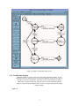
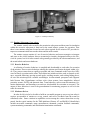


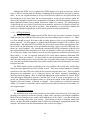

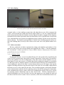
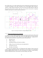

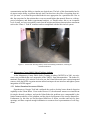
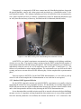
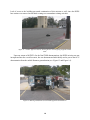

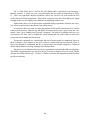
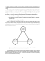

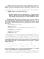


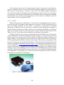
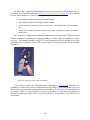
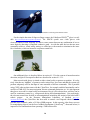

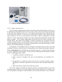


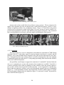
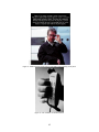
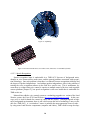

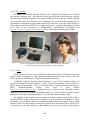


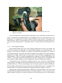
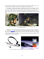

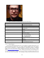
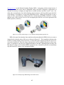


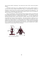
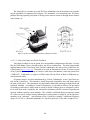
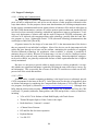
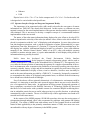


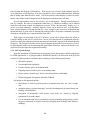

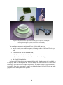
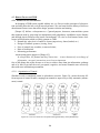
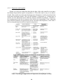


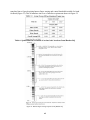


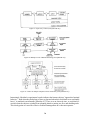
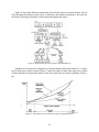


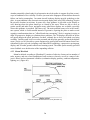
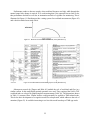
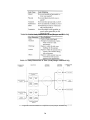
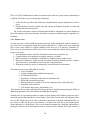
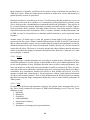
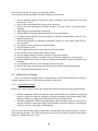
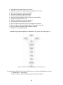
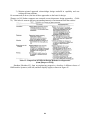


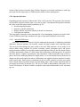
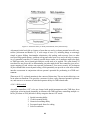
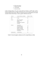
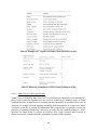

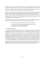


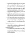
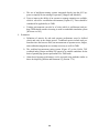
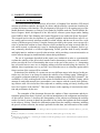


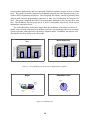
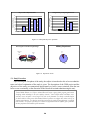

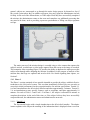
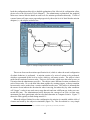
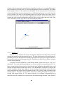

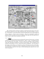
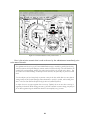
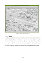
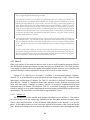


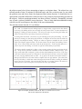

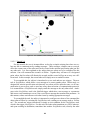
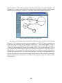


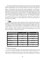
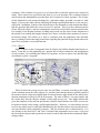
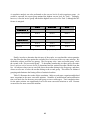
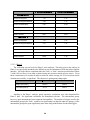
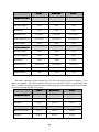
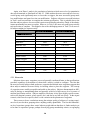
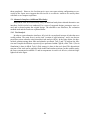
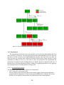

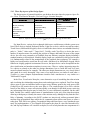
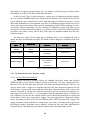
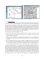
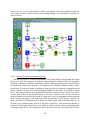


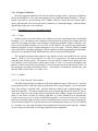
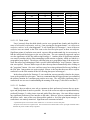
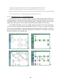


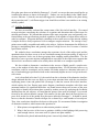


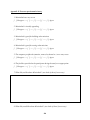

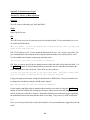

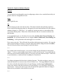
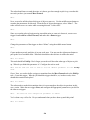
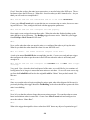
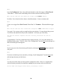

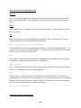

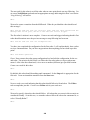
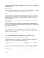


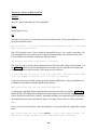

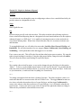


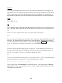


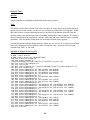


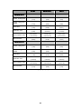
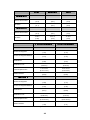
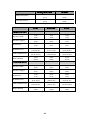
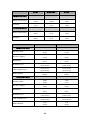


![User's Manual AH-160M Series [Hardware & Software]](http://vs1.manualzilla.com/store/data/006866992_1-bebe17d6e04075ac71fce0bfab0e4653-150x150.png)