1
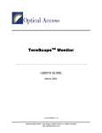
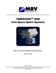
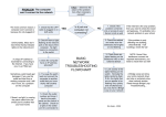
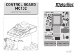
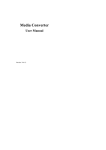
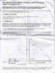
Media Converter
MC102F/XX
User Manual
ML46179 Rev. 02
MC102F/XX
User Manual
Standards Compliance
UL 1950; CSA 22.2 No 950; FCC Part 15 Class A; CE-89/336/EEC, 73/23/EEC
©2001 Optical Access Inc.
i
MC102F/XX
User Manual
Table of Contents
Chapter 1 ............................................................................ 1
Introduction to the 102F/XX Media Converter...................................................... 1
Introduction.............................................................................................................. 1
Application............................................................................................................... 1
Front Panel ............................................................................................................... 3
Technical Specifications ........................................................................................ 4
Chapter 2 ............................................................................ 5
Installation................................................................................................................ 5
Slide Switch Configuration ...................................................................................... 7
Setting the Switches Manually .............................................................................. 7
Contact Information............................................................................................... 9
ii
MC102F/XX
User Manual
Chapter 1
Introduction to the
102F/XX Media
Converter
Introduction
The MC102 product line is a two-port switch used to adapt
different Ethernet interfaces in a multitude of ways. Different
adaptations include copper-to-fiber and fiber-to-fiber with a
choice of multimode fiber, single mode fiber, single fiber
operation, different wavelengths and power levels. The copper
port has the auto-negotiation feature and is a 10/100BaseTX. Using
switching technology, the 102F/XX Media Converter provides
important advantages over other simple repeaters or converters.
The most important distinction is the separation of collision
domains and error packets filtering between the two ports.
Application
Replacing network backbones with fiber and upgrading cable
segments in order to deliver more bandwidth to the desktop
creates a steady increase of mixed media environments. As a
result, copper and fiber cabling must coexist as homogeneous
elements of the network. Media converters can seamlessly
connect copper and fiber cabling and enable network managers
to expand the network. Economics usually dictate that these
circuits are multimode. If applications need to be extended to
other buildings or cities a single mode fiber is utilized. Moreover,
dark fibers contracted from public carriers are usually single mode.
media converters have the options of multimode and single mode
fiber conversion, as well as, conversion between multimode and
single mode fibers.
1
MC102F/XX
User Manual
Over the last few years, local area network traffic has exploded.
Network managers today are facing a barrage of users who are
demanding increasing more bandwidth. Applications such as
videoconferencing, multimedia presentations and electronic
imaging have become more and more popular, causing existing
infrastructures to collapse under the heavy demand. In many
cases IT managers seek efficient ways to utilize existing fibers. One
method is to use single fiber for full-duplex transmission. For this
specific application most of our converters have an option for
single fiber operation (on single mode fiber).
Figure 1 Copper to Single Fiber, Singlemode fiber or Multimode
fiber Conversion
2
MC102F/XX
User Manual
Front Panel
The table below describes the front panel, the various
components , LED indications and their functions.
Description
Function
ETH 10/100
Copper input connection
TX RX
Fiber optic link
DC IN
DC cable connection. The voltage polarities of
the port are:
Global LEDS
Name
Color/Type
of Light
Function
PWR
Green
Power LED - ON = power up
OFF = power down
LNK
Green
On: Established connection
FLK
Green
On: Established connection to
fiber optic link
SPD
Green
On: 100 Mbps connection
ACT
Green
Network signal activity (Tx or Rx)
FRX
Green
Receive a signal from the fiber
optic port.
3
MC102F/XX
User Manual
Technical Specifications
Parameters
MC102F/XX Requirements
Input Voltage (V)
DC: 6.5 ± 7.5 1 Amps*
Maximum Power
Consumption (W)
12W
Size: Width x Depth x
Height
180x120x640 mm
17.4 x 16.15 x 24 inches
Weight
.362 kg / 0.798 lbs.
Operating
Temperature
0 °C to 50°C / 32°F to 122°F
Storage Temperature
-40 °C to +70°C/-58°F to 158°F
Humidity
85% maximum, non-condensing
Standards
Compliance
UL 1950; CSA 22.2 No 950; FCC Part 15
Class A; CE-89/336/EEC, 73/23/EEC
* The external power supply is included with the 102F/XX Media
Converter.
4
MC102F/XX
User Manual
Chapter 2
Installation
The following describes the MC102F/XX media converter, its
installation and configuration procedures as follows:
1.
Connect the enclosed power supply to the DC IN input
connector.
2.
Connect the power supply to the line source.
100 – 240 VAC 50 – 60 Hz
3.
Verify the LED PWR is activated.
4.
Verify that the opposite side is configured to the factory
default, FORCE 100 Mb/s for the fiber optic link.
NOTE:
There is an option to set the MC102F to auto negotiation by selecting internal slide
switch.
5.
Connect Ethernet copper RJ-45 cable to ETH 10/100.
NOTE:
Use a straight cable for host connection or crossed cable for switch or hub
connection.
6.
Verify the LED LINK is active.
7.
Connect fiber optic cable with a suitable connector, SC
Duplex or SC Simplex or MT-RJ, to the optical F/O connector.
8.
Verify the LED FLK is active.
5
MC102F/XX
User Manual
9.
Verify connectivity by sending traffic (Ping).
10.
Verify the LED’s SPD, ACT and FRX are active.
NOTE:
In event of any malfunction use the RESET feature. Use a small sharp object to
press the button within the hole in the top- front of the device.
Figure 2 MC102F/XX
6
MC102F/XX
User Manual
Slide Switch Configuration
The slide switch chip provides the MC102 converter with more
flexibility and switching options. In order to set the switch to the
desired setting the user must open unit’s cover and adjust the slide
switches manually.
Figure 3 Slide Switch
Setting the Switches Manually
1.
Unscrew the MC102F/XX top cover.
2.
Remove the protective covering from the switching unit.
3.
Use a small sharp object to set the switch to the desired
setting.
4.
Reinstall the converter’s protective covering and connect
the converter as described in this chapter.
7
MC102F/XX
User Manual
The table below describes the switch position and which feature is
enabled.
Label
Description
Feature Enabled
NC
Not Connected
The switch is not connected.
FDC
Full Duplex Flow
Control
OFF – Disable flow control (default).
Half Duplex Flow
Control Disable
OFF – Disable flow control (default).
Duplex Mode
When A.N is ON Auto-Negotiation is
disabled.
HDC
D-F
ON – Enable IEEE802.3x Paused based
flow control.
ON – Enable “forced collision” flow
control.
OFF – Set to full Duplex(default).
ON – Set to half Duplex.
100M
Speed Setting
When A.N is ON (Auto-Negotiation is
disabled).
OFF – Set to 100 Mbps (default).
ON – Set to 10 Mbps.
A.N.
AutoNegotiation
enable
OFF – Set to Auto-Negotiation.
ON – The port speed is set by 100M
(default).
The duplex is set by D-F
NOTE:
As the default the slide switch is configured to forced 100 Mbps.
8
MC102F/XX
User Manual
Contact Information
If you have any questions or encounter any difficulties with this
device contact your local Optical Access representative or your
Customer Service Representative.
Contact
USA
1-818-773-0900
International
972-4-993-6200
[email protected]
www.opticalaccess.com
9