1
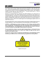
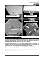
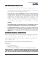
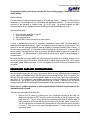
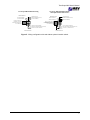
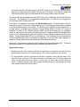
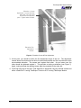
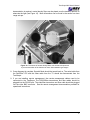
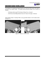
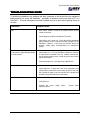
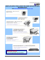
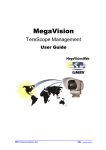
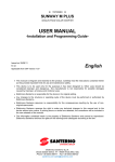
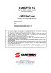
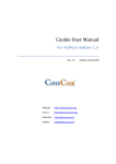
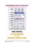
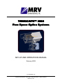
TERESCOPETM 3000 Free Space Optics Systems SET-UP AND OPERATIONS MANUAL February 2003 (170-00-830951-5.0) 10343 Roselle Street San Diego, California 92121 (858) 792-8501 www.mrv.com TABLE OF CONTENTS Section Page # Introduction...................................................................................................................... 1 Safety Warning ................................................................................................................ 1 Eye Safety ....................................................................................................................... 2 Regulatory Compliances ................................................................................................. 3 Site Preparation Check List ............................................................................................. 4 Standard Mounting Instructions ....................................................................................... 4 Standard Cabling Instructions.......................................................................................... 5 Equipment Recommended for Set-up and Alignment...................................................... 8 Initial Alignment Procedure.............................................................................................. 8 Weather Shield Installation............................................................................................ 14 Squelch Mode................................................................................................................ 15 Maintenance & Service.................................................................................................. 15 Troubleshooting Guide .................................................................................................. 17 Warranty Information ..................................................................................................... 18 Contact Information ....................................................................................................... 18 Appendix A: Hole Pattern for TereScope 3000............................................................. 19 Appendix B: Mounting Options ..................................................................................... 20 Appendix C: Optional Close Range Attenuator............................................................. 26 Appendix D: Product Specifications.............................................................................. 28 Complete MRV Communications Product Line.............................................................. 29 i LIST OF FIGURES & TABLES Figure # Page # Figure 1 MRV Communications' TereScope 3000 transceiver terminal ................... 1 Figure 2 Warning label ............................................................................................. 2 Figure 3 Warning label placements on the TereScope 3000.................................... 3 Figure 4 Diagram of Electronics Box........................................................................ 6 Figure 5 Wiring configuration with and without optional interlock switch .................. 7 Figure 6 Elevation Course & Fine Adjustment........................................................ 10 Figure 7 Azimuth Fine Alignment & Lock-down Screws ......................................... 11 Figure 8 Picture of laser aligned in center of detector ............................................ 12 Figure 9 Picture of laser misaligned to the left ....................................................... 12 Figure 10 Placement of neutral density filters .......................................................... 13 Figure 11 Weather Shield Installation ...................................................................... 14 Figure A-1 Hole Pattern for TereScope 3000............................................................. 19 Figure B-1 Mountable Gimbal .................................................................................... 20 Figure B-2 M001 Angle Bracket................................................................................. 20 Figure B-3 Wall Pedestal Mount ................................................................................ 21 Figure B-4 Floor Pedestal Mount ............................................................................... 22 Figure B-5 M015 Reinforced Floor Pedestal Mount................................................... 23 Figure B-6 Extended Wall Mount ............................................................................... 24 Figure C-1 CRA Mount Installed ................................................................................ 26 Figure C-2 Attenuator Installed in Mount ................................................................... 27 Table # Table C-1 ii Page # T3000 Proper Neutral Density Filter Selection ......................................... 27 TereScope 3000 User’s Manual INTRODUCTION INTRODUCTION Thank you for your purchase of our TereScopeTM Free Space Optics system. Along with the TereScope, you should have received copies of support software for your particular system. Please read this set-up and operations manual and support documentation before installing and operating the TereScope equipment. Figure 1. MRV Communications’ TereScope 3000 transceiver terminal. MRV Communications is committed to providing our customers with products of the finest quality and construction. If you have any questions or would like more information regarding your system, please contact us in the United States at (858) 792-8501. MRV Communications’ TereScope 3000 free space optics system provides a wireless data communication link between two line-of-sight points. The TereScope 3000 typically supports data rates between 10 Mbps and 155 Mbps. Because these systems are protocol-independent, they are capable of transmitting Ethernet, Fast Ethernet, FDDI, ATM and a variety of proprietary protocols. Acting as a simple wireless repeater, the TereScope can be directly connected to a user’s LAN without altering the form of the data transmitted. The link consists of two transceiver terminals (see Figure 1). Line-of-sight must be available between the two links. This manual provides the user with enough information to install and maintain the TereScope 3000 system in the field. Please refer to our Site Survey Guide for information about site preparations and mounting considerations prior to beginning the installation of the systems. Although technical information and operating instructions are provided in this manual, the user should never attempt to open the TereScope optical heads or try to make alterations not specified in this document. Any attempt to perform maintenance not detailed in this manual could be potentially hazardous and will void your warranty. SAFETY WARNING Set-up and operation of the TereScope 3000 is not complicated; however, to achieve optimum performance and ensure a safe work environment, you should read through this manual completely before you begin the installation process. CAUTION – Use of controls or adjustments or performance of procedures other than those specified herein may result in hazardous laser radiation exposure. 1 TereScope 3000 User’s Manual EYE SAFETY The TereScope 3000 is a Class 3R laser product as defined by EN 60825-1:1994 & IEC 60825-1/A2: 2001. Under normal operating conditions, the light output is equivalent to a Class 1M laser product as defined by the Center for Devices and Radiological Health (CDRH); however, under single-fault conditions, the light output can reach Class 3R levels. The typical radiant power is 7 mW per transmit aperture for a total output power of 21 mW. Although the TereScope 3000 laser transmitters meet ANSI standards for eye safety when not viewed with binoculars or other optical collecting devices at the telescope output aperture (the TereScope 3000 emits 1.35 mW/cm2), you should avoid looking directly into the laser aperture during operation. Warning labels are affixed to the TereScope 3000 units and serve as a reminder that care should be exercised when working with any laser system (see Figure 2). The lasers operate at a wavelength of 785 nm, which is in the infrared region of the electromagnetic spectrum and is not visible to the human eye. The warning label shown in Figure 2 has been affixed to the housing at multiple locations to indicate the laser classification. Figure 3 shows placement of the warning label on the TereScope 3000. CAUTION – An LED indicator is located on the back cap of the TereScope indicating that the laser is emitting light. This LED is a two-color LED, red and green, which will appear pale red during normal operation. If this LED changes color to either dark red or to green, discontinue use of the TereScope and contact MRV Communications for instructions. The user should never attempt to open the optical housing. Doing so could expose the user to Class 3B diode laser power up to 50 mW in the 780-860 nm range and may result in hazardous laser radiation contact. Vorischt-wenn andere als die hier angebenen Kontrollfunktionen oder Einstellungen oder die Ausführung von Abläufen, Kann zu einer Aussetzung von gefährlicher Strahlung führen. Figure 2. Warning label 2 TereScope 3000 User’s Manual Warning label on weather shield. (Labels appear on both sides of weather hi ld) Warning labels on housing. (Labels appear on both sides of housing) Laser aperture labels on front window. Warning label on aft cap. Figure 3. Warning label placement on the TereScope 3000 REGULATORY COMPLIANCES COMPLIANCES This device complies with the regulations for laser radiation control established by the Center for Devices and Radiological Health, which is part of the Food and Drug Administration under the U.S. Department of Health and Human Services, 21 CFR Chapter 1, Subchapter J. This device complies with part 15 of the FCC Rules. Operation is subject to the following two conditions: (1) This device may not cause harmful interference, and (2) this device must accept any interference received, including interference that may cause undesired operation. This device also complies with EC Directives 89/336/EEC (EMC) and 73/23/EEC (Low Voltage Directive), and is labeled with the CE mark. Changes or modifications not expressly approved by the party responsible for compliance could void the user’s authority to operate the equipment. 3 TereScope 3000 User’s Manual SITE PREPARATION CHE CHECK CK LIST Before you begin installation of the TereScope 3000 units, you should quickly check the following items (a more detailed procedure for site preparation can be found in the Site Survey Guide): Verify that the fiber transceiver wavelength (either 1310 nm or 850 nm) on your switch/router matches the fiber transceiver wavelength of the TereScope unit. For data transmission, 2 strands of multimode fiber optic cable (do not use single-mode fiber unless the single mode option unit has been ordered) should be run with enough length to comfortably reach the TereScope unit. ST connectors should be used unless other arrangements have been made with MRV Communications in advance. If remote management will be used, additional cabling must be run from the control room to the TereScope. An additional 3 strands of multimode fiber (for a total of 5 strands), two for the serial line and one for video, need to be run from the control room to the TereScopes for remote management. Running additional strands of multimode fiber is recommended for redundancy. Fiber transceivers both in the electronics box of the TereScope and the control room will be required. Contact MRV Communications for more details about the fiber transceivers. We recommend using fiber optic cable instead of copper for rooftop installations to avoid the risk of exposing computer equipment in your control room to the threat of lightning strikes. A weather rated power source must be available. This line should be isolated from other heavy equipment (such as air conditioners) and should provide either 100-120 or 200-240 VAC (depending on the configuration), between 50 and 60 Hz, with at least a 15 Amp capability unless other arrangements have been made with MRV Communications in advance. STANDARD MOUNTING INSTRUCTIONS INSTRUCTIONS Due to the narrowness of the laser beam used by the systems, precise alignment is critical to optimal performance of the TereScope and a rigid mounting surface must be found. The bolt circle on the base plate of the TereScope is 6 inches in diameter. The units can therefore be mounted directly to a concrete ledge on the rooftop if it is at least 8 inches wide. A variety of mounting options are displayed in Appendix B of this manual. More information on different mounting scenarios can be found in the Site Survey Guide. Standard Mounting Procedure (mounting to a concrete wall top 8 inches wide) Supplies needed: Four 3/8” concrete anchors Appropriate drill for above anchors Drill Template Provided in Appendix A (or the unit can be set in place and holes marked) Using the template provided or the TereScope itself, orient so that the template or link is facing towards the opposite site. The base plates are slotted to allow for 15 degrees of course adjustment in both directions. First, mark the hole locations. Drill the appropriate holes using a masonry/concrete drill bit. Once the holes have been drilled, the unit may be bolted in place with the concrete anchors. 4 TereScope 3000 User’s Manual All appropriate safety procedures, including the use of safety goggles, should be observed during drilling. Optional Mounts: The same basic mounting procedures apply to all TereScope mounts. Typically, the mount will be anchored to a concrete structure on the building with appropriate anchors. The unit will then be mounted to the pedestal or bracket using (4) 3/8-16 bolts. All mounts supplied by MRV Communications have a complete bolt circle enabling any Azimuth orientation of the unit. Optional mount types: 1. 2. 3. 4. Floor mounted pedestals or tripods Wall mounted pedestals Wall angle brackets Consult MRV Communications for other options A tripod is approved as a mount for temporary installations (contact MRV Communications for additional information about tripods). Again, it is important to place the tripod on a rigid surface. If the tripod is on the roof, place the tripod as close as possible to the edge (preferably near a corner). If the roof surface seems “soft”, it is advisable to place the tripod on top of plywood. In fact, the tripod can be bolted to the plywood from below by removing the tripod’s rubber footpads that reveal 1/2-13 threaded holes. It is also advisable to weigh down the tripod and/or plywood using sandbags or concrete blocks. Be certain that the mounts are stable and have been securely affixed to the building structure. Once the unit is bolted in place, the weather shield should be installed using the eight 6-32 x 5/16 screws and sixteen fender washers provided. Do not over tighten the screws as the acrylic weather shield may crack. STANDARD CABLING INS INSTRUCTIONS TRUCTIONS We recommend running the AC power, the two data fibers, and any optional remote management control cables to a weatherproof junction box close to the mounting location. From this junction, the fiber and AC power and the remote management cables will be run to the TereScope electronics box (see Figure 4). For installations using remote management, at least five strands of multimode fiber should be run: two for data, two for RS232 data, and one for video. If fibers are run for remote management, fiber/RS-232 and fiber/RG-59 transceivers will be required inside the electronics box. Please note: a qualified electrician or other properly trained individual should supervise the installation of the AC cable. There are two main methods for doing this. 1. Remove the AC cable (if present) from the TereScope electronics box and run weatherproof flexible ¾” NPT conduit from the junction box to the AC knockout in the electronics box. The AC wiring should be connected using wire no smaller than 18 AWG terminated with either #6 ring terminal lugs or #6 flanged spade terminal lugs. The wires should be connected to the terminal block in the electronics box as shown in Figure 4. The ground wire should be approximately ½” longer than both the hot and neutral wires. 5 TereScope 3000 User’s Manual 2. As a temporary connection, 100-120VAC units are shipped with outdoor rated AC cables. In this configuration, for temporary outdoor installations, a weather-rated outlet with a cover should be wired within 4 feet of the installation location. The fiber should be routed directly to the unit’s electronics enclosure through flexible ¾” NPT conduit. Fiber should be terminated with ST connectors. Terminals are provided for the option of installing an interlock switch (see right side of Figure 5). An interlock switch will turn off the laser power if the switch opens. For example, if the switch were attached to a lab door and someone opens the door, the lasers will turn off. The lasers will only be on if the interlock switch is closed or shorted. If this option is desired, the user-supplied interlock switch should be connected using wire no smaller than 18 AWG terminated with #6 terminal lugs. If desired, the two data fiber cables can be run in the same conduit as the AC, or the other hole in the TereScope electronics box can be used (recommended if running more than one pair of fiber.) The two data fibers and the AC power lines are the minimum requirements to operate the laser link. If remote management is desired, additional cabling needs to be run. A 6 or 12 strand fiber can be run up to the junction box and terminated with ST connections. ST-ST patch cable can then be routed through the conduit. Remote management requires that two multimode fibers for the RS-232 data and one fiber for the video data are run to the TereScope. In the TereScope electronics box, fiber/RS-232 and fiber/RG-59 transceivers will convert the fiber signals to RS-232 serial and RG-59 video signals. In the control room, if fiber is run, transceivers will be required to convert the fiber signals back to RS-232 and RG-59 signals. The RS-232 & RG-59 signals will then be plugged into the remote management computer. Figure 4. Diagram of Electronics Box. 6 TereScope 3000 User’s Manual TereScope 3000 Installation Wiring Internal Harness TereScope 3000 Installation Wiring With Optional Interlock Switch Internal Harness (WHITE OR BLUE) (WHITE OR BLUE) (BLACK OR BROWN) (GREEN OR GREEN/YELLOW) (BLACK OR BROWN) (GREEN OR GREEN/YELLOW) (BLACK OR BROWN) (BLACK OR BROWN) (BLACK OR BROWN) (BLACK OR BROWN) DO NOT ALTER LAST 4 POSITIONS - FACTORY CONFIGURATION FOR 110 / 220 V OPERATION DO NOT ALTER LAST 4 POSITIONS - FACTORY CONFIGURATION FOR 110 / 220 V OPERATION Interlock Switch LINE IN (BLACK OR BROWN) LINE IN (BLACK OR BROWN) GROUND IN (GREEN OR GREEN/YELLOW) GROUND IN (GREEN OR GREEN/YELLOW) NEUTRAL IN (WHITE OR BLUE) NEUTRAL IN (WHITE OR BLUE) Interlock Switch Figure 5. Wiring configuration with and without optional interlock switch. 7 TereScope 3000 User’s Manual EQUIPMENT RECOMMENDED FOR SETSET-UP AND ALIGNMENT ALIGNMENT Voice communication devices (i.e. 2-way radio or cellular phones) Medium blade screwdriver #2 Phillips screwdriver 3/16" hex driver 5/16” hex driver 7/16” open ended wrench Television monitor with video input jack Adapter cable from monitor to BNC (i.e. RCA to BNC) PalmPilot™1 or PC with MRV Communications supplied software installed The set-up will be nearly the same at both ends of the link. recommended equipment on hand. Each side should have the INITIAL ALIGNMENT PROCEDURE PROCEDURE To turn on the TereScope 3000 system, first make sure that the power is correctly connected and functioning. Turn the power switch to the ON position. (See Figure 4 for power switch location). The red LASER POWER indicator on the back of the optical transceiver should now be visible which indicates that the transmit lasers are now on. Although the TereScope laser transmitters meet ANSI standards for eye safety at the transmit aperture, fault conditions could occur that will increase the laser output above eye safety limits. Never look in the direction of the other transceiver through binoculars, which could magnify the apparent intensity, and avoid looking directly into the transmit apertures of any TereScope 3000. The spotting scope mounted beneath the weather shield has been treated with a special IR filter which makes it eye-safe during an installation. The TereScope 3000 was designed for easy and quick alignment. The two diagnostic tools that greatly simplify the alignment are a TV (or other video monitor) and a PalmPilot™ or laptop PC. 1. Set up a TV BW NTSC standard or other video monitor that is shaded from the sun. Open up the electronics box. Attach a RG-59 video coaxial cable to the BNC video connector located inside the electronics box (see Figure 3) and plug the other end of the cable into the video input of the TV (a BNC-to-RCA adapter may be required). The TV will be used for visual alignment, monitoring the laser light as it approaches the detector. 2. Plug in either a PalmPilot™ running the TereScope Control software or a laptop PC running the TereScope Monitor software to the RS-232 serial port located connector located inside the electronics box (see Figure 3). The PalmPilot™ Control or PC Monitoring software will display quantitative information about link quality during alignment. 3. If a data source (such as a switch or router) is available, plug in the fibers from that data source to the DATA fiber ports located inside the electronics box of the TereScope. It is important to match 1 8 PalmPilot™ is a registered trademark of 3Com Corporation. TereScope 3000 User’s Manual the transmit fiber from the data source to the DATA IN port at the TereScope, and the receive fiber from the data source to the DATA OUT port at the TereScope. One method to distinguish fibers that are paired is that one of the fibers will have writing printed on the outer jacket. If an active data source is plugged into the DATA IN port of the TereScope, then the DATA IN light comes ON. The TereScope is now transmitting modulated light. If no data source is plugged into the TereScope, DATA IN light will be OFF. At this point, it is important to know about the Squelch Mode feature. If Squelch Mode is ON, the lasers will be turned off if there is no data being sent to the TereScope (more information is provided in the Squelch Mode section of this manual). The default mode of operation is Squelch Mode ON. If no data source is available during alignment, Squelch Mode should be turned OFF using the PalmPilot™’s Control or PC’s Monitor software. Select “Sq Off” on the laser menu of TereScope Control or make sure that the Transmit Squelch check box in the Advanced/APD/Laser Enable Menu is clear in the TereScope Monitor (see the TereScope Control or Monitor software manual for more details). Turning Squelch Mode OFF will turn the lasers on. The TereScope will now be transmitting random modulated light, which is necessary for alignment of the other side. When alignment is complete, Transmit Squelch should be turned back ON for best performance. Note that if no data source is plugged into the TereScope, the transmit light will be OFF. IF Squelch Mode is then turned OFF to turn on the lasers, the transmit light will remain OFF. Alignment Procedure: 1. Sighting along the tube, coarsely point the unit towards its counterpart in the Azimuth axis by rotating the entire unit on its mounting bolts. Once close to alignment, lock in place. 2. If a large elevation motion is necessary (more than 5 degrees), loosen the two bolts on the black lever arm using the 7/16” open end wrench and loosen the 3/8” Socket head cap screw on that same side of the gimbal. At this point, the entire tube will pivot about its center. Using the spotting scope, point roughly towards the other unit and tighten the three bolts loosened previously (see Figure 6). 9 TereScope 3000 User’s Manual Elevation - Course Adjustment. Loosen both hex bolts with 7/16” open end wrench and set elevation pitch. Tighten when finished. Elevation Fine Adjustment Screws Figure 6. Elevation Course & Fine Adjustment. 3. At this point, you should be within the fine adjustment range of the unit. The adjustment screws above the electronics box allow for azimuth adjustment and the ones below the tube accommodate elevation. The screws work against each other. As you loosen one, the other should be tightened against it. This provides a locking mechanism (see Figure 7). Again, looking through the spotting scope, align the crosshairs to the other site. 4. Once both sites are at this point, final alignment is performed using the internal camera and either a PalmPilot™ running TereScope Control or a PC running TereScope Monitor. 10 TereScope 3000 User’s Manual Figure 7. Azimuth Fine Alignment & Lock-down Screws. 5. Watch the TV as the fine alignment screws are adjusted. The TV is monitoring the internal camera that is focused on the detector. The center of the detector is located in the center of the display. The goal is to adjust the alignment such that the light from the other unit is centered on the detector (see Figures 8 and 9 for examples). Note that the appearance of the detector on the screen may be affected by the amount of ambient light. For this reason, the picture will appear brighter during the day and darker at night. In addition, it may be necessary to cover the TV monitor during the day if there is too much ambient light to see the image on the screen. Once both units are aligned, double check that the adjustment screws are tight against each other and that the top lock down screw on the azimuth axis is tight (see Figure 7). 6. If not connected earlier, connect a data source at both ends of the link. Verify that Squelch Mode is ON. The transmit light should illuminate when the local data source has been plugged in; and once the opposite end of the link is transmitting, then the receive light should also be lit. 11 TereScope 3000 User’s Manual Figure 8. Picture of laser aligned in center of detector. Figure 9. Picture of laser misaligned to the left. Note that this image may be lighter due to the presence of more ambient light during installation. 7. At the main window of your TereScope Control or TereScope Monitor interface, you should be able to determine the value of the receive signal strength indicator (RSSI). If the RSSI lies between 1.9 and 2.35, there should be enough signal-to-noise to receive data with a bit error rate (BER) of 10-9 or better. If there is not enough modulated light (due to either misalignment or very poor visibility conditions), the RSSI will drop below 1.9 and the bit error rate will begin to increase. If there is too much light, then there is the chance that the detector will become saturated and the TereScope will stop receiving data. This can occur if the TereScopes are set up too close to each other (<10 m) for demonstration purposes. If two TereScopes are set up 800 meters apart and slowly brought together, the RSSI will rise as the distance between the TereScopes decreases. This is because the received power increases as the range decreases. As the range gets smaller, the RSSI value will increase to a maximum value of 2.35. As the range continues to decrease, the RSSI will level off at 2.35, but the detector current will continue to rise. Once the detector current reaches a value of ~400 µA, saturation of the detector will occur and the link will stop functioning. Detector current can be monitored with the TereScope monitoring software. If a short-range 12 TereScope 3000 User’s Manual demonstration is required, neutral density filters can be placed over the transmit aperture to attenuate the light (see Figure 10). More information can be found in the section on close range set-ups. Figure 10. Placement of neutral density filters over the transmit apertures to prevent saturation of the detector at close, demonstration-type ranges. 8. Once alignment is complete, Squelch Mode should be turned back on. The serial cable from the PalmPilot™/PC and the video cable from the TV should be disconnected from the TereScope. 9. If you are installing remote management, the remote management cables need to be connected to the TereScope. The RS-232/fiber transceivers and fiber cables should be plugged into the RS-232 port. The video/fiber transceiver and fiber cable should be plugged into the video BNC connector. See the remote management documentation provided for operational instructions. 13 TereScope 3000 User’s Manual WEATHER SHIELD INSTALLATION INSTALLATION The hardware kit for installing the Weather Shield to your TereScope 3000 system will be taped to the inside of the Weather Shield. The Weather Shield Mounting Hardware Kit will contain the following: - 18-8 Stainless Steel Large-OD Flat Washer #6 Screw Size => Quantity 8 - 18-8 SS Round Head Phillips Machine Screw 6-32 Thread, 3/8" Length => Quantity 8 Attach Weather shield to TereScope 3000 unit using provided hardware in the 8 locations shown. (See figure 11) Figure 11. Installation of Weather Shield. 14 TereScope 3000 User’s Manual SQUELCH MODE TereScope 3000 systems come with the Transmit Squelch Mode of operation. When Transmit Squelch Mode is enabled, the laser will be turned off when there is no signal on the incoming fiber. If Transmit Squelch Mode is disabled, the laser will be randomly modulated. This has been found to cause problems with some communication protocols, specifically FDDI. These problems occur when a transmit fiber is disconnected, causing the remote switch to see the random modulation. The remote switch interprets this as a bad connection and shuts down its own transmitter, causing the same problem at the local switch. To avoid these problems, Transmit Squelch Mode is the default mode of operation. During system installation, however, a data source is not always available. In this case, it may be necessary to disable Transmit Squelch Mode in order to keep the laser on for alignment. Transmit Squelch Mode may be enabled or disabled with TereScope Monitor version 1.01 or higher, or TereScope Control for PalmPilot™ version 1.11 or higher, through the laser enable controls. When alignment is complete, Transmit Squelch should be re-enabled for best performance. MAINTENANCE & SERVICE SERVICE MAINTENANCE: Very little maintenance is required to assure the performance of your TereScope system. The Lexan window at the front of the transceiver should be cleaned periodically. To avoid radiation exposure at the window aperture, turn off the system power using the power switch on the back of the telescope. Wipe the window using a regular glass cleaner and soft cloth or lint-free paper towel. We recommend cleaning approximately every three months; however, depending on weather conditions, the window may require more frequent attention. The Lexan material that the window is fabricated from will slowly yellow with exposure to sunlight and the atmosphere. Slight yellowing will not affect the performance of the system. Check the laser exposure warning labels for fading from the sun (see Figure 2). If they are faded and difficult to read, contact MRV Communications for replacement labels. Your TereScope has been equipped with an anticorrosive device, an emitter designed to protect components against corrosion in non-ventilated housings. The emitter releases a vapor into the interior of the electronics box, which then deposits on the metal surfaces, forming a protective molecular layer. This emitter is non-toxic and is safe to handle and apply. This emitter has been designed to help protect the TereScope’s electronics box for two years. If the access door is opened frequently, replace more often than two years. If the emitter is moist, due to moisture in the electronics box, it is recommended that the emitter be replaced. Contact your MRV Communications service representative for replacements. 15 TereScope 3000 User’s Manual CAUTION – An LED indicator is located on the back cap of the TereScope indicating that the laser is emitting light. This LED is a two-color LED, red and green, which will appear pale red during normal operation. If this LED changes color to either dark red or to green, contact MRV Communications Technical Support Services for instructions. Please note: The units should be powered down with the Laser Enable key switch prior to performing routine maintenance. Take care when standing near or touching the TereScope unit. It takes very little motion to cause the units to become misaligned. If this occurs, realign the system using the fine alignment procedure described previously in this manual. SERVICE: The TereScope 3000 is not field-serviceable. Contact MRV Communications to obtain instructions regarding product service by our personnel. Do not attempt to remove the protective housing from the back of the unit. Tamper-resistant screws will indicate if the cap has been taken off, and the warranty will be void. The user should never attempt to open the optical housing. Doing so could expose the user to Class 3B diode laser power up to 50 mW in the 780-860 nm ranges and may result in hazardous laser radiation contact. All defective equipment must be returned to MRV Communications for repair in the original shipping container. If MRV Communications’ Customer Support Services Department determines that your equipment, or any part of it, will need to be returned to the factory for repair, an RMA (Return Merchandise Authorization) number must be obtained prior to shipping equipment. Failure to obtain an RMA number prior to shipment will result in delays with repairing the equipment. The RMA number must be clearly marked on the outside of the shipping container. The equipment must be shipped via air, not ground service. 16 TereScope 3000 User’s Manual TROUBLESHOOTING GUIDE GUIDE To effectively troubleshoot any problems that arise, personnel on site should have the equipment listed previously for set-up and installation - specifically a television monitor and either a PC or a PalmPilot™. If remote management has been installed, this can be done without gaining access to the units. Indication Potential Cause Remote Receive Light is out on one side • Other unit’s laser has been disabled. Check to see that the laser lockout switch is turned to the position where the key cannot be removed • Check alignment of BOTH units with the TV monitor. • Laser failure on the other unit. Check the monitor photodiode (MPD) readouts on the TereScope monitoring program or the PalmPilot™ interface. If they read zero and the lasers are enabled, contact MRV Communications for replacement options. • Other unit may not be “transmitting”. Check to see that the transmit light is on. This is an indication of whether or not there is a data source connected to the unit. Without a data source, the TereScope transmits noise - which can give a false receive light at close ranges. • If the transmit light is on, verify alignment of BOTH units. • Check the fiber connection between the switch and TereScope. • Check alignment. If either end of the link is misaligned, most switches will re-route traffic to the backup (if there is one) and won’t provide a signal to the unit until the link is aligned and provides an open channel for the router/switch. • Check ON/OFF switch. • Verify AC line in. • Possible DC power Communications. Remote Receive Light is intermittent or the Receive Signal Strength (RSSI) is low and erratic. Data In LED is off All LED’s are off supply failure. Contact MRV 17 TereScope 3000 User’s Manual WARRANTY INFORMATION INFORMATION LIMITED WARRANTY MRV Communications warrants its equipment to be in good working order for thirteen (13) months from the date of shipment. If equipment proves to be defective and MRV Communications is notified within the warranty period, MRV Communications will, at its option, repair or replace the equipment at no charge. All repairs will be done at MRV Communications’ repair facility. Damage to equipment resulting from negligence, misuse, tampering or acts of God is not covered by this warranty. MRV Communications will make every effort to rerun your equipment to you as quickly as possible. Shipping costs for the return of equipment for repair by MRV Communications shall be the responsibility of the purchaser. All defective equipment must be returned to MRV Communications for repair in the original shipping container. If MRV Communications’ Technical Support Department determines that your equipment, or any part of it, will need to be returned to the factory for repair, an RMA number must be obtained prior to shipping equipment. Failure to obtain an RMA number prior to shipment will result in delays with repairing the equipment. This number must be marked clearly on the outside of the shipping container. Limitations of Liability: Except for liability allowed by applicable law, (I) in no event shall MRV Communications be liable under any legal theory, however caused, for any loss of profits, loss of business, loss of use or data, interruption of business, or for indirect, special, incidental or consequential damages of any kind, even if MRV Communications has been advised of the possibility of such damages and (II) in no event will MRV Communications’ aggregate liability arising out of or related to this warranty exceed the amount paid or payable to MRV Communications for the defective equipment. These limitations of liability will continue beyond the expiration of this warranty. This warranty is in lieu of all other warranties, express or implied or statutory, including any warranty of merchantability or fitness for a particular purpose. CONTACT US Equipment Return Address: Attn: Technical Services Center MRV Communications - San Diego Operations 10343 Roselle Street San Diego, California 92121 Phone: 858-657-9663 Fax: 858-657-9677 E-mail: [email protected] www.mrv.com www.opticalaccess.com 18 TereScope 3000 User’s Manual APPENDIX A: HOLE PATTERN PATTERN FOR TERESCOPETM 3000 Figure A-1. Hole Pattern for TereScope 3000. 19 TereScope 3000 User’s Manual APPENDIX B: MOUNTING MOUNTING OPTIONS Figure B-1. Mountable Gimbal - Direct to a flat wall surface. Attach with 4-3/8" concrete anchors. Figure B-2. M001 Angle Bracket - Use when the wall is too thin to mount to the top. Can be used on inner or outer wall surface (reversible). 20 Mountable Gimbal Footprint Interface material: concrete or metal M001 – Angle Bracket Mount Interface material: concrete or metal TereScope 3000 User’s Manual WALL PEDESTAL MOUNTS Figure B-3. Wall Pedestal Mount - Used when the link needs to be elevated above the top of a wall. M054 – 12 inch M053 – 24 inch M060 – 24 inch w/ spacer M022 – 36 inch M053 – 24” Wall Pedestal Mount Interface material: concrete or metal M054 – 12” Wall Pedestal Mount Interface material: concrete or metal M022 – 36” Wall Pedestal Mount Interface material: concrete or metal 21 TereScope 3000 User’s Manual FLOOR PEDESTAL MOUNTS Figure B-4. Floor Pedestal Mount - Similar to the Wall Pedestal Mount. Interface material: concrete M055 – 24 inch M050 – 36 inch M015 – 48 inch Interface material: metal M057 – 24 inch M058 – 36 inch M059 – 48 inch M050 – 36” Floor Pedestal Mount Interface material: concrete 22 M055 – 24” Floor Pedestal Mount Interface material: concrete M057 – 24” Floor Pedestal Beam Mount Interface material: metal TereScope 3000 User’s Manual FLOOR PEDESTAL MOUNTS (con’t) M058 – 36” Floor Pedestal Beam Mount Interface material: metal Figure B-5. M015 Reinforced Floor Pedestal Mount - Similar to the Standard Floor Pedestal. Standard length: 48". M059 – 48” Floor Pedestal Beam Mount Interface material: metal M015 – 48” Reinforced Floor Pedestal Mount Interface material: concrete 23 TereScope 3000 User’s Manual EXTENDED WALL MOUNTS Figure B-6. Extended Wall Mount – Used when a standard wall pedestal mount is insufficient to clear obstacles or for applications requiring an extension from the wall for better access to the transceiver. Interface material: concrete M051 – 24 inch M056 – 36 inch Interface material: metal M062 – 24 inch M063 – 36 inch M056 – 36” Extended Wall Concrete Mount Interface material: concrete 24 M051 – 24” Extended Wall Concrete Mount Interface material: concrete M062 – 24” Extended Wall Beam Mount Interface material: metal TereScope 3000 User’s Manual EXTENDED WALL MOUNTS (con’t) M063 – 36” Extended Wall Beam Mount Interface material: metal 25 TereScope 3000 User’s Manual APPENDIX C: OPTIONAL OPTIONAL CLOSE RANGE ATTENUATOR ATTENUATOR The TereScope 3000 was designed to operate at ranges up to 3.75 km. If the TereScope 3000 units are set up too close together, there will be too much light at the detector and the detector will saturate. If the TereScopes are to be set up 1000 meters or less apart, the optional Close Range Attenuator needs to be installed in the front of both TereScope units. Mount Attachment Procedure Important: Mount Attachment Procedure is to install mounts that were not factory installed. If unit was shipped with attenuator mount, proceed to the next section entitled Attenuator Use. 1. Remove the three Phillips head screws shown in Figure C-1. 2. Fill the holes in the Lexan with Clear RTV. The RTV will act as a seal inside the screw holes. Do not wait for the RTV to dry, proceed immediately. 3. Line up the Attenuator Mount with the three screw holes and attach with three 6-32 x 7/8" Phillips head screws. Do not over torque the screws as cracking of the Lexan may occur. Tighten enough to fully compress the gasket and no more. 4. Lubricate the threads of the mount where the attenuator threads in with an anti-seize compound or grease to prevent galling the aluminum. Remove and replace with 7/8” (3 places) Figure C-1. CRA Mount Installed. Attenuator Use Depending on range, a number of different combinations of ND filters can be used. They are stackable and thread into one another. To start, it is recommended that the following chart be used to determine the correct filter. Once systems are in place and aligned, filters may be added or removed to obtain maximum performance. 26 TereScope 3000 User’s Manual Table C-1. T3000 Proper Neutral Density Filter Selection. Link Range 0 - 75 m Optical Density of Neutral Density Filter ND 3.0 B+W filter Number 110 75 - 500 m 500 - 1000 m Over 1000 m 1.8 0.9 No Attenuator needed 106 N/A No Attenuator needed Hoya filter number 1 Hoya ND400 or 3 Hoya ND (x8) 2 Hoya ND(x8) 1 Hoya ND (x8) No Attenuator needed Too much power can result in saturation of the detector and ultimately poor link performance. Too little power can result in inadequate link margin for poor weather conditions. After the link is installed, the amount of filter should be adjusted for maximum receive power during clear visibility. This means: RSSI = 2.38 to 2.42 HV varies by unit Current (I) 0.200 to 0.300 mA (200 to 300 micro amps on Palm Pilot) (as close to .300 mA as possible without going over) Installation Procedure 1. Install the filters into the mount by gently threading them in. Do not force them. 2. If the filter selection requires more than one filter, each filter can be threaded into one another. 3. If the installation is to be permanent, caulk the filter joints to prevent water from leaking in between and filling with water. Standard clear RTV provides a good watertight seal. Figure C-2. Attenuator Installed in Mount. 27 TereScope 3000 User’s Manual APPENDIX D: TERESCOPE TERESCOPETM 3000 TRANSCEIVER SPECIFICATIONS SPECIFICATIONS Transmitter: Laser Type Laser Class Laser Wavelength Transmit Beam Diameter at Aperture Transmit Beam Divergence Average Output Power Maximum Range (clear conditions) Transmit Beam Diameter at 1 km Allowable Mis-pointing Angle Single Mode AlGaAs Laser Diode Class 3R 785 nm 50 mm (2 in) 2.5 mrad 7 mW (typical) per aperture, 21 mW (typical) total 3.75 km 2.5 m (typical) 0.8 mrad Receiver: Detector Receiver Field of View Bit Error Rate Receiver Diameter Receiver Area Minimum Receive Power (average) Scintillation Fade Margin (at max. range) Allowable Atmospheric Attenuation (at max. range) APD 2.8 mrad -9 < 10 200 mm (8 in) 2 2 0.021 m (32 in ) 100 nW (over receiver area) 7.5 dB 15 dB (visibility ≥ 2.5 miles) Fiber Optic Interface: Line Data Rate Center Wavelength Fiber Link Length Input Optical Power Output Optical Power (62.5/125 µm fiber) (50/125 µm fiber) Interface Connectors 10-200 Mbps (full duplex) 1310 nm (850 nm option) 2000 m (1.24 miles) (max.) -28 dBm avg. (min.); -14 dBm avg. (max.) -18.5 dBm avg. (min.); -14 dBm avg. (max.) -22.0 dBm avg. (min.); -14 dBm avg. (max.) ST Mechanical and Power: Operating Temperature Dimensions Weight Input Power Line Operating Power (Including Heaters) -30°C to 50°C (-22°F to 122°F) 31.25" long x 16.7" wide x 22.68" high 65 lbs 100-240 VAC*, 50-60 Hz, single-phase, 3A *Configured at the factory 350 W Operational Diagnostics: Alignment via CCD Camera Receive and Transmit Data Lights PalmPilot and Windows based monitoring software Monitors receive signal level, laser, and temperature RS-232 based interface Specifications subject to change without notice 28 TereScope 3000 User’s Manual K KE EE EP PU UP PW WIIT TH HT TH HE EL LA AT TE ES ST T IIN NF FR RE EE ES SP PA AC CE EO OP PT TIIC CS S T TE EC CH HN NO OL LO OG GY Y!! Visit www.opticalaccess.com or www.mrv.com COMING SOON! Our next generation line of products. 29