1
AN3209
Application note
Developing your M24LR64-R datalogger application
for temperature acquisition
Introduction
The M24LR64-R is a Dual interface EEPROM. Since it has both an 13.56 MHz ISO 15693
RFID and a 400-kHz I2C interface, the device is a good solution for RF-enabled sensors for
which ST has developed a reference design. One of the main benefits brought by the
M24LR64-R is that the sensor data can be accessed in read and write mode without
consuming any on-board power.
This application note presents a practical useful application for the M24LR64-R datalogger.
It describes an autonomous battery-powered datalogger able to record and store 64 Kbits of
temperature data using the M24LR64-R Dual interface EEPROM (I2C and RF). The
datalogger microcontroller is an STM8L101K3. It communicates with the M24LR64-R using
its serial interface and controls an STTS75 digital temperature sensor.
An on-board demonstration firmware, the M24LR64-R_Datalogger_application_firmware,
stored in the STM8L101K3 memory selects and controls the temperature acquisition
through a RFID reader connected by a USB cable to a PC.
The application is delivered with a PC software, the M24LR64R_Datalogger_application_software, to configure and control the datalogger, as well as
download and display the temperature values.
ST provides all the resources required to develop your own datalogger application and PC
software:
●
Source files of the data logger firmware (M24LR64R_Datalogger_application_firmware): they allow implementing I2C communications
between the M24LR64-R, the STTS75, and the STM8L101K3.
●
Source files of the PC software (M24LR64-R_Datalogger_application_software): they
control RF communications between the M24LR64-R and an RFID reader.
Basic information about the M24LR64-R, STTS75, and STM8L101K3 component
characteristics, as well as a description of the algorithms for the datalogger firmware and PC
software are provided in this document.
Reference documents
●
M24LR64-R datasheet
●
“M24LR64-R tool driver install guide” user manual (UM0863)
●
“Using the M24LR64-R datalogger reference design” user manual (UM0925)
●
“How to manage M24LR64-R data transfers from the I²C bus or an RF channel”
application note (AN3057)
●
STM8L101K3 datasheet
●
STM8L101 reference manual (RM0013).
●
STTS75 datasheet.
The documents are available from http://www.st.com/dualeeprom.
June 2010
Doc ID 17419 Rev 1
1/42
www.st.com
Contents
AN3209
Contents
1
2
Overview of M24LR64-R datalogger application . . . . . . . . . . . . . . . . . . 6
1.1
Board architecture . . . . . . . . . . . . . . . . . . . . . . . . . . . . . . . . . . . . . . . . . . . 6
1.2
Communication interfaces . . . . . . . . . . . . . . . . . . . . . . . . . . . . . . . . . . . . . 7
1.3
Power management . . . . . . . . . . . . . . . . . . . . . . . . . . . . . . . . . . . . . . . . . . 7
Component overview . . . . . . . . . . . . . . . . . . . . . . . . . . . . . . . . . . . . . . . . 8
2.1
2.2
2.3
M24LR64-R Dual interface EEPROM . . . . . . . . . . . . . . . . . . . . . . . . . . . . 8
2.1.1
M24LR64-R main features . . . . . . . . . . . . . . . . . . . . . . . . . . . . . . . . . . . . 8
2.1.2
M24LR64-R I2C interface . . . . . . . . . . . . . . . . . . . . . . . . . . . . . . . . . . . . . 9
2.1.3
M24LR64-R RF Interface . . . . . . . . . . . . . . . . . . . . . . . . . . . . . . . . . . . . 11
2.1.4
Datalogger memory mapping . . . . . . . . . . . . . . . . . . . . . . . . . . . . . . . . 12
STM8L101K3 8-bit low power microcontroller . . . . . . . . . . . . . . . . . . . . . 15
2.2.1
STM8L101K3 overview . . . . . . . . . . . . . . . . . . . . . . . . . . . . . . . . . . . . . 15
2.2.2
STM8L101K3 I2C interface . . . . . . . . . . . . . . . . . . . . . . . . . . . . . . . . . . 16
2.2.3
STM8L101K3 configuration . . . . . . . . . . . . . . . . . . . . . . . . . . . . . . . . . . 17
Digital temperature sensor . . . . . . . . . . . . . . . . . . . . . . . . . . . . . . . . . . . . 18
2.3.1
STTS75 main features . . . . . . . . . . . . . . . . . . . . . . . . . . . . . . . . . . . . . . 18
2.3.2
STTS75 I2C interface . . . . . . . . . . . . . . . . . . . . . . . . . . . . . . . . . . . . . . . 19
2.3.3
STTS75 I2C commands . . . . . . . . . . . . . . . . . . . . . . . . . . . . . . . . . . . . . 19
2.3.4
Temperature format . . . . . . . . . . . . . . . . . . . . . . . . . . . . . . . . . . . . . . . . 20
3
Installing the datalogger package on your computer . . . . . . . . . . . . . 22
4
Developing, compiling and debugging your datalogger firmware . . . 24
4.1
Installing the datalogger application firmware . . . . . . . . . . . . . . . . . . . . . 24
4.2
Software tool-chain overview . . . . . . . . . . . . . . . . . . . . . . . . . . . . . . . . . . 24
4.3
5
ST Visual Develop (STDV) . . . . . . . . . . . . . . . . . . . . . . . . . . . . . . . . . . . 24
4.2.2
C compilers . . . . . . . . . . . . . . . . . . . . . . . . . . . . . . . . . . . . . . . . . . . . . . 24
Description of the datalogger firmware . . . . . . . . . . . . . . . . . . . . . . . . . . 25
4.3.1
Main routine . . . . . . . . . . . . . . . . . . . . . . . . . . . . . . . . . . . . . . . . . . . . . . 25
4.3.2
Acquisition algorithm functions . . . . . . . . . . . . . . . . . . . . . . . . . . . . . . . 27
PC software . . . . . . . . . . . . . . . . . . . . . . . . . . . . . . . . . . . . . . . . . . . . . . . 28
5.1
2/42
4.2.1
Description of the PC software . . . . . . . . . . . . . . . . . . . . . . . . . . . . . . . . . 28
Doc ID 17419 Rev 1
AN3209
Contents
5.1.1
START button algorithm . . . . . . . . . . . . . . . . . . . . . . . . . . . . . . . . . . . . . 29
5.1.2
STOP button algorithm . . . . . . . . . . . . . . . . . . . . . . . . . . . . . . . . . . . . . 30
5.1.3
TRACE GRAPH button algorithm . . . . . . . . . . . . . . . . . . . . . . . . . . . . . 30
5.1.4
Timer management . . . . . . . . . . . . . . . . . . . . . . . . . . . . . . . . . . . . . . . . 31
Appendix A Temperature acquisition datalogger schematics . . . . . . . . . . . . . . 33
Appendix B M24LR64-R RF commands . . . . . . . . . . . . . . . . . . . . . . . . . . . . . . . . 36
B.1
Inventory . . . . . . . . . . . . . . . . . . . . . . . . . . . . . . . . . . . . . . . . . . . . . . . . . . 36
B.2
Reset to Ready . . . . . . . . . . . . . . . . . . . . . . . . . . . . . . . . . . . . . . . . . . . . . 36
B.3
Read single block . . . . . . . . . . . . . . . . . . . . . . . . . . . . . . . . . . . . . . . . . . . 37
B.4
Read Multiple Block. . . . . . . . . . . . . . . . . . . . . . . . . . . . . . . . . . . . . . . . . . 37
B.5
Write single block . . . . . . . . . . . . . . . . . . . . . . . . . . . . . . . . . . . . . . . . . . . 38
B.6
estar commands . . . . . . . . . . . . . . . . . . . . . . . . . . . . . . . . . . . . . . . . . . . . 38
Appendix C STTS75 I2C commands . . . . . . . . . . . . . . . . . . . . . . . . . . . . . . . . . . . 39
6
C.1
Acquire temperature . . . . . . . . . . . . . . . . . . . . . . . . . . . . . . . . . . . . . . . . . 39
C.2
Read acquired Temperature . . . . . . . . . . . . . . . . . . . . . . . . . . . . . . . . . . . 39
Revision history . . . . . . . . . . . . . . . . . . . . . . . . . . . . . . . . . . . . . . . . . . . 41
Doc ID 17419 Rev 1
3/42
List of tables
AN3209
List of tables
Table 1.
Table 2.
Table 3.
Table 4.
Table 5.
Table 6.
Table 7.
Table 8.
Table 9.
Table 10.
Table 11.
Table 12.
Table 13.
Table 14.
Table 15.
Table 16.
Table 17.
4/42
M24LR64-R signal names . . . . . . . . . . . . . . . . . . . . . . . . . . . . . . . . . . . . . . . . . . . . . . . . . . 8
I2C page write function . . . . . . . . . . . . . . . . . . . . . . . . . . . . . . . . . . . . . . . . . . . . . . . . . . . . 10
I2C buffer read function. . . . . . . . . . . . . . . . . . . . . . . . . . . . . . . . . . . . . . . . . . . . . . . . . . . . 10
M24LR64-R-R memory organization . . . . . . . . . . . . . . . . . . . . . . . . . . . . . . . . . . . . . . . . . 12
Status byte values . . . . . . . . . . . . . . . . . . . . . . . . . . . . . . . . . . . . . . . . . . . . . . . . . . . . . . . 13
Overwrite byte values . . . . . . . . . . . . . . . . . . . . . . . . . . . . . . . . . . . . . . . . . . . . . . . . . . . . . 13
Delay byte values . . . . . . . . . . . . . . . . . . . . . . . . . . . . . . . . . . . . . . . . . . . . . . . . . . . . . . . . 13
Relationship between temperature and digital output. . . . . . . . . . . . . . . . . . . . . . . . . . . . . 20
Component values for schematics . . . . . . . . . . . . . . . . . . . . . . . . . . . . . . . . . . . . . . . . . . . 35
Inventory_DataLogger() . . . . . . . . . . . . . . . . . . . . . . . . . . . . . . . . . . . . . . . . . . . . . . . . . . . 36
ResetToReadyRF_DataLogger() . . . . . . . . . . . . . . . . . . . . . . . . . . . . . . . . . . . . . . . . . . . . 36
ReadRF_single_DataLogger() . . . . . . . . . . . . . . . . . . . . . . . . . . . . . . . . . . . . . . . . . . . . . . 37
ReadRF_multiple_DataLogger() . . . . . . . . . . . . . . . . . . . . . . . . . . . . . . . . . . . . . . . . . . . . . 37
WriteSingleBlockRF_DataLogger(). . . . . . . . . . . . . . . . . . . . . . . . . . . . . . . . . . . . . . . . . . . 38
I2C_SS_Config(). . . . . . . . . . . . . . . . . . . . . . . . . . . . . . . . . . . . . . . . . . . . . . . . . . . . . . . . . 39
I2C_SS_Config(). . . . . . . . . . . . . . . . . . . . . . . . . . . . . . . . . . . . . . . . . . . . . . . . . . . . . . . . . 40
Document revision history . . . . . . . . . . . . . . . . . . . . . . . . . . . . . . . . . . . . . . . . . . . . . . . . . 41
Doc ID 17419 Rev 1
AN3209
List of figures
List of figures
Figure 1.
Figure 2.
Figure 3.
Figure 4.
Figure 5.
Figure 6.
Figure 7.
Figure 8.
Figure 9.
Figure 10.
Figure 11.
Figure 12.
Figure 13.
Figure 14.
Figure 15.
Figure 16.
Figure 17.
Figure 18.
Figure 19.
Figure 20.
Figure 21.
Figure 22.
Figure 23.
Figure 24.
Figure 25.
Figure 26.
Figure 27.
Datalogger front side view . . . . . . . . . . . . . . . . . . . . . . . . . . . . . . . . . . . . . . . . . . . . . . . . . . 6
Datalogger back side view . . . . . . . . . . . . . . . . . . . . . . . . . . . . . . . . . . . . . . . . . . . . . . . . . . 6
STM8L101K3/M24LR64-R/STTS75 communication block diagram. . . . . . . . . . . . . . . . . . . 7
Datalogger power management . . . . . . . . . . . . . . . . . . . . . . . . . . . . . . . . . . . . . . . . . . . . . . 7
M24LR64-R pinout . . . . . . . . . . . . . . . . . . . . . . . . . . . . . . . . . . . . . . . . . . . . . . . . . . . . . . . . 8
M24LR64-R functional block diagram. . . . . . . . . . . . . . . . . . . . . . . . . . . . . . . . . . . . . . . . . . 8
Write I2C frame format . . . . . . . . . . . . . . . . . . . . . . . . . . . . . . . . . . . . . . . . . . . . . . . . . . . . . 9
Read I2C frame format . . . . . . . . . . . . . . . . . . . . . . . . . . . . . . . . . . . . . . . . . . . . . . . . . . . . 10
FEIG software support for windows . . . . . . . . . . . . . . . . . . . . . . . . . . . . . . . . . . . . . . . . . . 12
STM8L101K3 32-pin package pinout . . . . . . . . . . . . . . . . . . . . . . . . . . . . . . . . . . . . . . . . . 15
STM8L101K3 functional block diagram . . . . . . . . . . . . . . . . . . . . . . . . . . . . . . . . . . . . . . . 16
STTS75 temperature sensor pinout . . . . . . . . . . . . . . . . . . . . . . . . . . . . . . . . . . . . . . . . . . 18
STTS75 temperature sensor block diagram . . . . . . . . . . . . . . . . . . . . . . . . . . . . . . . . . . . . 18
Typical Pointer Set Configuration Register Write . . . . . . . . . . . . . . . . . . . . . . . . . . . . . . . . 19
Typical pointer set followed by a READ for 2-byte register. . . . . . . . . . . . . . . . . . . . . . . . . 20
M24LR64-R_Datalogger_Application_Software folder structure . . . . . . . . . . . . . . . . . . . . 22
M24LR64-R_Datalogger_Application_Software start menu . . . . . . . . . . . . . . . . . . . . . . . . 23
Needed material to compile and run an application on STM8L101K3 . . . . . . . . . . . . . . . . 24
Main routine algorithm . . . . . . . . . . . . . . . . . . . . . . . . . . . . . . . . . . . . . . . . . . . . . . . . . . . . 26
Acquisition_running algorithm. . . . . . . . . . . . . . . . . . . . . . . . . . . . . . . . . . . . . . . . . . . . . . . 27
Start_acquisition/stop_acquisition/acquisition update algorithms . . . . . . . . . . . . . . . . . . . . 27
M24LR64-R_Datalogger_application_software home page . . . . . . . . . . . . . . . . . . . . . . . . 28
START button algorithm . . . . . . . . . . . . . . . . . . . . . . . . . . . . . . . . . . . . . . . . . . . . . . . . . . . 29
STOP button algorithm . . . . . . . . . . . . . . . . . . . . . . . . . . . . . . . . . . . . . . . . . . . . . . . . . . . . 30
TRACE GRAPH algorithm . . . . . . . . . . . . . . . . . . . . . . . . . . . . . . . . . . . . . . . . . . . . . . . . . 31
Dynamic view - timer algorithm. . . . . . . . . . . . . . . . . . . . . . . . . . . . . . . . . . . . . . . . . . . . . . 32
Temperature acquisition datalogger schematics . . . . . . . . . . . . . . . . . . . . . . . . . . . . . . . . 34
Doc ID 17419 Rev 1
5/42
Overview of M24LR64-R datalogger application
AN3209
1
Overview of M24LR64-R datalogger application
1.1
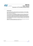
Board architecture
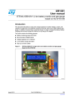
The entire circuit is implemented on a 90x50 mm PCB board which integrates the three ST
components (M24LR64-R, STTS75, and STM8L101K3) plus a 20x40 mm antenna
connected to the dual EEPROM RF interface. The system is supplied from a 3 V battery
(BR2330) fixed on the back side of the PCB as shown in Figure 2.
The board is equipped with a connector which provides an easy access to the STM8L101K3
SWIM signal required to program the microcontroller and debug the firmware (see Figure 2).
This reference board allows the SDA and the SCL I2C signals to be probed using dedicated
connectors.
Figure 1.
Datalogger front side view
Temperature Sensor (STTS75)
Microcontroller (STM8L)
Dual Interface EEPROM
(M24LR64-R)
Antenna
AI18019b
Figure 2.
Datalogger back side view
Battery
SWIM connector
AI18020b
6/42
Doc ID 17419 Rev 1
AN3209
1.2
Overview of M24LR64-R datalogger application
Communication interfaces
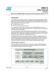
The communications between the STM8L101K3, M24LR64-R, and STTS75 are performed
through an I2C bus. The STM8L101K3 acts as the I2C master, and both the M24LR64-R
and STTS75 act as slaves. The Dual interface EEPROM is also connected to an antenna to
communicate with the RFID reader. Refer to Figure 3 for an overview of the communication
interfaces.
Figure 3.
STM8L101K3/M24LR64-R/STTS75 communication block diagram
3LAVE
3443
TEMPERATURESENSOR
-ASTER
34-,
-ICROCONTROLLER
)#
)#
3LAVE
-,2 $UAL)NTERFACE %%02/-
)#
!NTENNA
!)
1.3
Power management
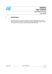
The datalogger is a low power application requiring a particular power management. The
entire power supply is managed by the microcontroller which is the only device directly
powered by the battery (see Figure 4). Both slave nodes and I2C power supply (VCC) are
powered by the STM8L101K3 microcontroller.
Figure 4.
Datalogger power management
-ASTER
34-,
-ICROCONTROLLER
6$$
3443
$
6$$
$
6$$ -,22
$
6##
"ATTERY
3$!
3#,
!)
Doc ID 17419 Rev 1
7/42
Component overview
2
AN3209
Component overview
This section describes the main characteristics of the three STMicroelectronics components
(M24LR64-R, STTS75, and STM8L101K3). It explains how to configure them for the
temperature acquisition application, and it describes the corresponding code function and
examples.
2.1
M24LR64-R Dual interface EEPROM
2.1.1
M24LR64-R main features
The M24LR64-R device is a dual-access electrically erasable programmable memory
(EEPROM). It features an I2C interface and can be operated from a VCC power supply. It is
also a contactless memory powered by the received carrier electromagnetic wave.
The M24LR64-R is organized as 8192x8 bits in the I2C mode and 2048x32 bits in the
ISO 15693 and ISO 18000-3 mode 1 RF mode.
Figure 5.
M24LR64-R pinout
%
!#
!#
633
6##
%
3#,
3$!
!)
M24LR64-R functional block diagram
2OWDECODER
Figure 6.
%%02/-
,ATCH
!#
2&
,OGIC
2&6 ##
0OWERMANAGEMENT
) #
3#,
3$!
!#
#ONTACT6 ##
6##
633
!)
Table 1.
8/42
M24LR64-R signal names
Signal name
Function
Direction
E0, E1
Chip Enable
Input
SDA
Serial Date
I/O
SCL
Serial Clock
Input
Doc ID 17419 Rev 1
AN3209
Component overview
Table 1.
M24LR64-R signal names (continued)
Signal name
Function
Direction
AC0, AC1
Antenna coils
I/O
VCC
Supply voltage
VSS
Ground
M24LR64-R I2C interface
2.1.2
The M24LR64-R can work both in standard and Fast I2C modes. The device carries a builtin 4-bit device type identifier code (1010b) compliant with the I2C bus definition. For the
demonstration application, the STM8L101K3 master operates at a speed of 100 kHz.
The M24LR64-R behaves as a slave for the I2C protocol with all memory operations
synchronized by the serial clock. The device I2C address is 1010 0000b (0xA0)
The I2C master writes and reads to/from the M24LR64-R memory. These basic operations
are performed by the M24LR64-R_Datalogger_application_firmware by calling i2c_ee.c
library functions.
Write operations
To write to the memory, the I2C master sends write commands to the M24LR64-R. The
command frame must be compliant with the format described in Figure 7.
The M24LR64-R_Datalogger_application_firmware calls the I2C_EE_PageWrite function
which programs a set of bytes into the EEPROM (see Table 2 for a description and an
example).
Write I2C frame format
!#+
$EV3ELECT
3TART
0AGE7RITE
!#+
"YTEADDRESS
!#+
"YTEADDRESS
!#+
!#+
$ATAIN
$ATAIN
!#+
$ATAIN.
3TOP
Figure 7.
27
!)
Doc ID 17419 Rev 1
9/42
Component overview
Read operations
Table 2.
AN3209
I2C page write function
Function description
Function name
Parameters
Return value
Example
I2C_EE_PageWrite(uint8_t* pBuffer, uint16_t WriteAddr,
uint8_t NumByteToWrite)
pBuffer: pointer to the buffer containing the data to be written to the EEPROM.
WriteAddr: internal address of the EEPROM where the data must be written.
NumByteToWrite: number of bytes to be written into the EEPROM.
ErrorStatus:
SUCCEEDED
FAILED
I2C_EE_PageWrite(s_data, 0x0002, 0x01) writes the content of the
buffer pointed by sedate at address 0x01.
To read from the memory, the I2C master can send read commands to the M24LR64-R. The
command frame must be compliant with the format described in Figure 8.
The M24LR64-R_Datalogger_application_firmware calls the I2C_EE_BufferRead
function which reads a set of bytes from the EEPROM (see Table 3 for a description and an
example).
Figure 8.
Read I2C frame format
!#+
3TART
$EVSELECT
!#+
"YTEADDRESS
"YTEADDRESS
27
!#+
!#+
!#+
$EVSELECT
3TART
3EQUENTIAL
2ANDOM
2EAD
!#+
$ATAOUT
27
./!#+
3TOP
$ATAOUT.
!)D
Table 3.
I2C buffer read function
Function description
Function
name
I2C_EE_BufferRead(uint8_t* pBuffer, uint16_t ReadAddr, uint8_t
NumByteToRead)
Parameters
pBuffer: pointer to the buffer where the data read from the EEPROM are stored.
ReadAddr:internal EEPROM address from which the read operation is performed.
NumByteToRead: number of bytes to read from the EEPROM.
ErrorStatus:
Return value SUCCEEDED
FAILED
Example
10/42
I2C_EE_BufferRead (s_data, 0x0002, 0x01) reads one byte from memory
address 0x01, and stores the value in the buffer pointed by s_data points.
Doc ID 17419 Rev 1
AN3209
2.1.3
Component overview
M24LR64-R RF Interface
In ISO 15693/ISO 18000-3 1 RF mode, the M24LR64-R is accessible via the 13.56 MHz
carrier electromagnetic wave. Incoming data are demodulated from the received signal
amplitude modulation (ASK: amplitude shift keying). The received ASK wave is 10% or
100% modulated with a data rate of 1.6 Kbit/s using the 1/256 pulse coding mode, or
26 Kbit/s using the 1/4 pulse coding mode.
Outgoing data are generated by the M24LR64-R load variation using Manchester coding
with one or two subcarrier frequencies at 423 kHz and 484 kHz. Data are transferred from
the M24LR64-R at 6.6 Kbit/s in low data rate mode and 26 Kbit/s high data rate mode. The
M24LR64-R supports the 53 Kbit/s in high data rate mode in one subcarrier frequency at
423 kHz. The M24LR64-R follows the ISO 15693/ISO 18000-3 mode 1 recommendation for
radio-frequency power and signal interface
RF commands are sent and decoded by the RFID reader. The demonstration application
can operate with FEIG and estar USB readers, for compliance with the available M24LR64R kits:
●
Development kit: FEIG reader
●
Demonstration kit: FEIG reader
●
Starter kit: estar reader
The commands depend on the type of reader.
The PC M24LR64-R_Datalogger_application_software is developed in Visual Basic. It
includes functions allowing to operate the datalogger with both FEIG and estar readers:
●
Inventory
●
Reset To Ready
●
Read Single Block
●
Write Single Block
●
Read Multiple Block
Refer to Appendix B: M24LR64-R RF commands for a detailed description of these
functions.
Doc ID 17419 Rev 1
11/42
Component overview
AN3209
FEIG commands
FEIG readers are delivered with a package to develop and program application software in
AINSI-C/C++, and Visual Basic (see Figure 9).
Figure 9.
FEIG software support for windows
*AVA.%4 .OTFREEOF
CHARGE
.%4LIBRARY
.%4
.%4
*AVALIBRARY
#CLASSLIBRARY
/")$)3#*
/")$)3#.%4
&%$-
&UNCTIONLIBRARIES$,,
&%&5
&%)3#
!PPLICATIONS,EVEL
&%#/-
&%53"
&%4#0
7INDOWS
DRIVER
$RIVER
/")$53"393
7INDOWS
DRIVER
53"
,!.
+ERNEL,EVEL
23
23
!)
Estar commands
Estar readers are delivered with a package to develop and program application software in
ANSI-C/C++, and Visual Basic. The following dll files are provided:
2.1.4
●
For Visual Basic: HIDdll.bas
●
For C/C++: HIDdll.h, HIDdll.lib
Datalogger memory mapping
The M24LR64-R memory is used as described in Table 4. The first two blocks of sector 0
contain critical system parameters, and application data.
Table 4.
12/42
M24LR64-R-R memory organization
Sector
number
RF block
address
i2C byte
address
bit [31:24]
bit [23:16]
bit [15:8]
bit [7:0]
0
0
0
RFU
Delay
Overwrite
Status
0
1
4
RFU
RFU
Nb Temp[1]
Nb Temp[0]
0
2
8
Temp2 [1]
Temp2 [0]
Temp1 [1]
Temp1 [0]
0
3
12
Temp4 [1]
Temp4 [0]
Temp3 [1]
Temp3 [0]
0
4
16
Temp6 [1]
Temp6 [0]
Temp5 [1]
Temp5 [0]
0
5
20
Temp8 [1]
Temp8 [0]
Temp7 [1]
Temp7 [0]
Doc ID 17419 Rev 1
AN3209
Component overview
Table 4.
M24LR64-R-R memory organization
Sector
number
RF block
address
i2C byte
address
bit [31:24]
bit [23:16]
bit [15:8]
bit [7:0]
...
...
...
...
...
...
...
63
2016
8064
Temp4092
[1]
Temp4092
[0]
Temp4091 [1] Temp4091 [0]
System bytes
●
Status byte
The Status byte shows the current application state. Refer to Table 5 for the meaning of
each possible value.
Table 5.
●
Status byte values
Status byte value
Description
0x11
START
0X22
PAUSED
0x33
RUNNING
0x44
STOPPED
0x55
UPDATE
0x66
OTHER
Overwrite byte
During the acquisition, the temperature values are stored in the memory. When the
memory is full, the application can either stop or rewrite data starting from the first
address, depending on the value of the Overwrite byte (see Table 6).
Table 6.
●
Overwrite byte values
Overwrite byte value
Description
0x11
Overwrite authorized
Any other values
Overwrite non authorized
Delay byte
The Delay byte contains the value of the acquisition rate (see Table 7):
Table 7.
●
Delay byte values
Delay byte value
Description (s)
Comment
0x0D
1
Temperature measured and saved every second
0x10
30
Temperature measured and saved every 30 seconds
Nb Temp bytes
NbTemp bytes contains the number of temperature values stored in the memory. It
consists in two hexadecimal-coded bytes. The number of temperature values is the
concatenation of Nb Temp[1] and Nb Temp[0] where Nb Temp[0] is the LSB and Nb
Doc ID 17419 Rev 1
13/42
Component overview
AN3209
Temp [1] is the MSB. For example, if Nb Temp [0] equals 0xF3 and Nb Temp [1] equals
0x02, then the number of acquired temperature values is 0x02F3 (755d).
Application data
●
Temp bytes
Tempx[0] and Tempx[1] contain the raw temperature (see Table 4), x ranging from 1 to
4092. For example if Tempx[0] = 0x1E and Tempx[1] is 0x80, the concatenation of
these two bytes gives the temperature value that is 0x1E80 corresponding to 30.5 °C
(according to the temperature sensor format).
The temperature format conversion is performed by issuing the following Visual Basic
command:
function convert_temp (TempToConvert As String) As Single
14/42
Doc ID 17419 Rev 1
AN3209
Component overview
2.2
STM8L101K3 8-bit low power microcontroller
2.2.1
STM8L101K3 overview
The STM8L101K3 (part number STM8L101K3T6) 8-bit low power microcontroller features
an enhanced STM8 CPU core which provides an increased processing power (up to 16
MIPS at 16 MHz) while maintaining the advantages of a CISC architecture of improved code
density, 24-bit linear addressing space and an optimized architecture for low power
operations (see Figure 10 and Figure 11).
For more details refer to the STM8L101K3 datasheet and to the STM8L101xx reference
manual (RM0013).
0 # )£ # ?3 # ,
0 # ( 3 5 3! 2 4 ? 2 8
0#(353!24?#+##/
0 # ( 3 5 3! 2 4 ? 4 8
0!(337)-"%%0)2?4)-
Figure 10. STM8L101K3 32-pin package pinout
0"(330)?-)3/
0! (3
0"(330)?- /3)
63 3
0"(330)?3#+
6$$
0"(330)?. 33
Doc ID 17419 Rev 1
0#)£#?3 $!
0"(34)-?42)'#/-0?#(
0 " ( 3 4 )- ? # ( # / -0 ? # ( 0! (3
0"(34)-?#(#/-0?#(
0"(34)-?#(#/-0?#(
0$(34)-?#(#/-0?#(
.2340!(3
!)
15/42
Component overview
AN3209
Figure 11. STM8L101K3 functional block diagram
6$$
-(ZINT2#
K(ZINT2#
6 $$ #LOCK
CONTROLLER
6OLTREG
#LOCKS
TOCOREAND
PER IPHERALS
.2 34
0/20$2
5PTO+BYTES
&LASHM EMORY
INCLUDING
UPTO+BYTES
DATA%%02/-
.ESTEDINTERRUPT
CONTROLLER
UPTO EXTERNAL
INTERRUPTS
+BYTES
32!-
$EBUGMODULE
37)-
!DDRESSANDDATAB US
) 2?4) -
)NFRAREDINTER FACE
0 !;=
0ORT!
0 ";=
0ORT "
0 #;=
0ORT #
0 $;=
0ORT $
6 $$ 6
TO6
63 3
2ESET
34-
#ORE
UPTO-(Z
37) -
0OWER
53!24
)£#
MULTIMASTER
28 4 8 #+
3$! 3 #,
30)
-/3 ) -) 3/ 3#+ .3 3
BIT4IMER
4)- ?#( ;=
4)- ?42) '
BIT4IMER
4)- ?#( ;=
4)- ?42) '
BIT4IMER
#/-0
)7$'
#/- 0?2% &
!75
"EEPER
#/-0
"%% 0
!)
2.2.2
STM8L101K3 I2C interface
The STM8L101K3 I2C peripheral allows multimaster and slave communications with bus
error management in standard (up to 100 kHz) or fast (up to 400 kHz) mode. In the
demonstration datalogger application, only the single master mode is used.
I2C synchronous communications require only two signals: SCL (Serial clock line) and SDA
(Serial data line). The corresponding port pins must be configured as floating inputs. Refer
to the STM8L101K3 datasheet for additional details.
To manage errors resulting from I2C and RF arbitration, an error management mode has
been implemented in the I2C library, i2c_ee.c, called by the M24LR64R_Datalogger_application_firmware (see AN3057 for details).
16/42
Doc ID 17419 Rev 1
AN3209
2.2.3
Component overview
STM8L101K3 configuration
Clock configuration
The STM8L101K3 microcontroller is configured as follows for the demonstration M24LR64R_Datalogger_application_firmware:
●
Master clock set to 2 MHz (minimum)
●
I2C, timer 2 (TIM2), Auto wakeup clocks enabled.
This is done by calling the following functions of the STM8L101 firmware library:
CLK_MasterPrescalerConfig(CLK_MasterPrescaler_HSIDiv8);
CLK_PeripheralClockConfig(CLK_Peripheral_I2C, ENABLE);
CLK_PeripheralClockConfig(CLK_Peripheral_TIM2, ENABLE);
CLK_PeripheralClockConfig(CLK_Peripheral_AWU, ENABLE);
I/O configuration
Three dedicated pins are set in output mode to power the Dual interface EEPROM, the
temperature sensor, and the I2C bus. This is done by using the following STM8L101
firmware library function:
GPIO_Init (GPIOD,GPIO_Pin_5 • GPIO_Pin_6 • GPIO_Pin_7,
GPIO_Mode_Out_PP_Low_Fast);
This example is illustrated in Figure 4.
Note:
It is recommended to set unused pins in input mode to minimize power consumption.
Auto wakeup configuration
The Auto wakeup (AWU) provides an internal wakeup timebase that can be used when the
microcontroller enters Active-halt power saving mode. This timebase is clocked by the low
speed internal (LSI) RC oscillator clock.
To ensure the best possible accuracy when using the LSI clock, its frequency can be
measured with TIM2 timer input capture 1, by calling the AWU_AutoLSICalibration
functions of the STM8L101 firmware library (see code example below):
AWU_AutoLSICalibration ();
AWU_Init (AWU_Timebase_1s);
AWU_Cmd (ENABLE);
/*The datalogger FW then issues the HALT instruction to switch the
microcontroller to Active-halt low power mode. In the following
function, command3 will automatically be executed 1second after
command2 according to the previous configuration */
void function (void)
{
command1 ;
command2 ;
halt ;
command3 ;
}
Doc ID 17419 Rev 1
17/42
Component overview
AN3209
2.3
Digital temperature sensor
2.3.1
STTS75 main features
The STTS75 is a high-precision CMOS digital temperature sensor IC with a programmable
9- to 12-bit analog-to-digital (ADC) converter and an I2C-compatible serial digital interface..
The STTS75 typically accuracy is ±3 °C over the full temperature measurement range of
–55 to 125 °C, and ±2°C in the –25 to 100°C range.
It operates from a 2.7 to 5.5 V supply voltage, with a typical supply current of 75 µA at 3.3 V.
For the demonstration datalogger application, the sensor is configured to the default
resolution settings that is 9 bits, to achieve a temperature resolution of 0.5 °C.
The STTS75 is factory-calibrated and requires no external components to measure
temperature.
Figure 12. STTS75 temperature sensor pinout
3$! 3#,
/3).4 '.$
6$$
!
!
!
!)
1. SDA and OS/INT are open drain.
Figure 13. STTS75 temperature sensor block diagram
4EMPERATURE
3ENSORAND
!NALOGTO$IGITAL
#ONVERTER!$#
#ONFIGURATION2EGISTER
0OINTER2EGISTER
4EMPERATURE2EGISTER
4(933ET0OINT2EGISTER
6$$
#ONTROLAND,OGIC
#OMPARATOR
4/33ET0OINT2EGISTER
3$!
!
!
/3
WIRE)#)NTERFACE
!
3#,
'.$
!)A
18/42
Doc ID 17419 Rev 1
AN3209
Component overview
STTS75 I2C interface
2.3.2
The STTS75 has a simple 2-wire I2C-compatible digital serial interface which allows to
access the data stored in the temperature register at any time.
It communicates via the serial interface with a master controller which operates at speeds
up to 400 kHz. However, for the demonstration datalogger application the master operates
at a speed of 100 kHz.
A0, A1, and A2 pins select the address and allow to connect to up to 8 devices on the same
bus without address conflict. For the demonstration application, A0, A1 and A2 are
connected to ground.
STTS75 I2C device address is 1001 0000b (0x90).
STTS75 I2C commands
2.3.3
The I2C master requests the sensor to acquire a temperature value and read the data from
the sensor register. These operations are performed by calling functions of the I2C library,
i2c_ee.c. Refer to Appendix C: STTS75 I2C commands for a detailed description of these
STTS75 functions.
Acquire temperature
To configure the temperature sensor in temperature acquisition mode, the I2C master sends
a Pointer Set Configuration Register Write frame as shown in Figure 14.
This is done by calling the I2C_SS_Config (uint16_t ConfigBytes) function.
Figure 14. Typical Pointer Set Configuration Register Write
3TART
BY
-ASTER
! ! !
7
$ $
0OINTER"YTE
!DDRESS"YTE
!#+
BY
3443
$ $ $ $ $
#ONFIGURATION"YTE
!#+
BY
3443
!#+
BY
3443
3TOP
#OND
BY
-ASTER
!)B
Doc ID 17419 Rev 1
19/42
Component overview
AN3209
Read acquired temperature
To read the 2 bytes temperature register, the I2C master must send a Pointer Set
Configuration Register Write frame followed by a 2-byte read frame (see Figure 15).
This operation is managed by calling the I2C_SS_BufferRead(unit8_t* pBuffer,
unit16_t ReadAddr, unit8_t NumberByteToRead) function.
Figure 15. Typical pointer set followed by a READ for 2-byte register
3TART
BY
-ASTER
! ! !
7
$ $
0OINTER"YTE
!DDRESS"YTE
!#+
BY
3443
2EPEAT
3TART
BY
-ASTER
! ! !
2
!#+
BY
3443
$ $ $ $ $ $ $ $
$ $ $ $ $ $ $ $
-OST3IGNIFICANT$ATA"YTE
!DDRESS"YTE
!#+
BY
3443
,EAST3IGNIFICANT$ATA"YTE
!#+
BY
-ASTER
3TOP
#OND
.O!#+
BY
BY
-ASTER
-ASTER
!)B
2.3.4
Temperature format
Table 8 shows the relationship between the output digital data and the external temperature
for 9 to 12-bit resolution. The left-most bit in the output data stream controls temperature
polarity information for each conversion. If the sign bit is '0', the temperature is positive and
of the sign bit is '1', the temperature is negative.
Table 8.
Relationship between temperature and digital output
Temperature
(°C)
Sign
Number of bits used by
conversion resolution
9
10
11
12
12-bit resolution
Digital
output
(Hex)
0000
11-bit resolution
0
0000
0
0
0000
0
0
0
0000
10-bit resolution
9-bit resolution
Always
zero
+125
0
111
1101
0
0
0
0
0000
7D00
+25.0625
0
001
1001
0
0
0
1
0000
1910
+10.125
0
000
1010
0
0
1
0
0000
0A20
+0.5
0
000
0000
1
0
0
0
0000
0080
20/42
Doc ID 17419 Rev 1
AN3209
Table 8.
Component overview
Relationship between temperature and digital output (continued)
9
10
11
12
Always
zero
Digital
output
(Hex)
0000
0
0
0
0
0000
0000
111
1111
1
0
0
0
0000
FF80
1
111
0101
1
1
1
0
0000
F5E0
1
110
0110
1
1
1
1
0000
E6F0
Temperature
(°C)
Sign
0
0
000
–0.5
1
–10.25
–25.0625
Number of bits used by
conversion resolution
Doc ID 17419 Rev 1
21/42
Installing the datalogger package on your computer
3
AN3209
Installing the datalogger package on your computer
To install the datalogger package on your computer:
1.
Execute the setup.exe file available from http://www.st.com/dualeeprom to install the
M24LR64-R_Datalogger_application_software and copies the following folders on
your computer (see Figure 16):
–
USB driver
–
.dll files
–
Source code of the M24LR64-R_Datalogger_application_firmware
The RFID reader must not be connected to your PC.
2.
When the installation is complete, connect the reader to the PC through an USB cable.
3.
To install the USB driver, follow the steps described in section 31. of user manual
UM0863 section 3.1.
Figure 16. M24LR64-R_Datalogger_Application_Software folder structure
22/42
Doc ID 17419 Rev 1
AN3209
Installing the datalogger package on your computer
Figure 17. M24LR64-R_Datalogger_Application_Software start menu
Doc ID 17419 Rev 1
23/42
Developing, compiling and debugging your datalogger firmware
AN3209
4
Developing, compiling and debugging your
datalogger firmware
4.1
Installing the datalogger application firmware
The source code of the demonstration M24LR64-R_Datalogger_application_firmware is
then available under C:\Program Files\M24LR64R_Datalogger_Application\sources\M24LR64-R_Datalogger_application_firmware
(see Figure 16) or by clicking Start > M24LR64-R_Datalogger_Application > M24LR64R_Datalogger_application_firmware.
4.2
Software tool-chain overview
To develop, compile and run an application software on an STM8L101K3 microcontroller,
the following software tool-chain components are required (see Figure 18):
●
Integrated development environment (IDE) composed of the ST Visual Develop
(STDV) and the ST Visual programmer software interface (STVP).
●
A C complier
●
The R-LINK hardware
Figure 18. Needed material to compile and run an application on STM8L101K3
$ATA,OGGER
2,).+
3 4 6 IS UAL$E VELOP
!)
4.2.1
ST Visual Develop (STDV)
STVD is a full-featured development environment. It is a seamless integration of the Cosmic
and Raisonance C compilers for STM8 microcontroller family. STDV software is available at
http://st.com/stonline/products/support/micro/files/sttoolset.exe.
To install STDV, download the installation software and follow each step of the installation
wizard. When the installation is complete, the executable is available under
START>Programs>ST Toolset > Development Tools> ST Visual Develop.
4.2.2
C compilers
The C compilers are integrated into the STDV development environment. They allow to
directly configure and control the building of your application through an easy-to-use
graphical interface. The demonstration application uses STM8 Cosmic C compiler (free
version up to 16 KBytes of code).
24/42
Doc ID 17419 Rev 1
AN3209
Developing, compiling and debugging your datalogger firmware
Cosmic compiler is available with the related documentation at
http://www.cosmicsoftware.com/download_stm8_16k.php.
Note:
4.3
1
You have to request a free license to use the compiler.
2
Refer to http://www.cosmic-software.com and http://www.raisonance.com for more
information on complier download, installation and configuration.
Description of the datalogger firmware
The M24LR64-R_Datalogger_application_firmware implemented in the STM8L101K3 is low
power oriented. It manages two power consumption modes:
●
Active consumption mode where the operations are executed by the application.
●
Low consumption mode: when no operation is ongoing, the application switches to low
consumption mode for a predefined delay.
The following sections describe the main and the acquisition routines, where the red
rectangles represent functions. Each function is described in details in a dedicated section.
4.3.1
Main routine
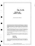
Figure 19 describes the flowchart of main.c file algorithm. main.c is located at C:\Program
Files\M24LR64-R_Datalogger_Application\sources\M24LR64R_Datalogger_application_firmware or by clicking Start > M24LR64R_Datalogger_Application > M24LR64-R_Datalogger_application_firmware.
The datalogger firmware is based on an infinite loop. The first operation checks the status
byte stored in the M24LR64-R dual mode EEPROM. This byte indicates the state of the
datalogger (STARTED or STOPPED).
Doc ID 17419 Rev 1
25/42
Developing, compiling and debugging your datalogger firmware
AN3209
Figure 19. Main routine algorithm
0OWER)#BUS
0OWERDUALMODE
%%02/-
3TATUS
"//4
9% 3
STOP?ACQUISITION
./
2EADDUALMODE
%%02/-3TATUSBYTE
%,3 %
3TATUS 50 $!4 %
ACQUISITION?UPDATE
3 4 !2 4
START?ACQUISITION
2 5..).'
ACQUISITION?RUNNING
5NPOWERSENSOR
5NPOWER
DUALMODE%%02/5NPOWER)#BUS
3WITCHTO!CTIVEHALTMODE
!)
26/42
Doc ID 17419 Rev 1
AN3209
4.3.2
Developing, compiling and debugging your datalogger firmware
Acquisition algorithm functions
Figure 20, Figure 21, and Figure 23 describe the algorithms corresponding to the redrectangle functions of the main routine (see Figure 19).
Figure 20. Acquisition_running algorithm
ACQUISITION?RUNNING
0OWERTEMPERATURE
SENSOR
9% 3
-EMORY&ULL
2EADDUALMODE
%%02/-
./
WRITETHESENSORTO
ACQUIREATEMPERATURE
/VERWRITE
!UTHORIZED
9% 3
START?ACQUISITION
./
READTHESENSORTOGETTHE
ACQUIREDTEMPERATURE
STOP?ACQUISITION
7RITETHETEMPERATUREIN
THEDUALMODE%%02/!)
Figure 21. Start_acquisition/stop_acquisition/acquisition update algorithms
START?ACQUISITION
STOP?ACQUISITION
ACQUISITION?UPDATE
WRITEDUALMODE$ELAY
"YTES
WRITEDUALMODE3TATUS"YTE
34/00%$
READDUALMODE$ELAY"YTE
READDUALMODE$ELAY"YTE
#ONFIGURE!75WITH$ELAY
"YTE6ALUE
#ONFIGURE!75WITH$ELAY
"YTE6ALUE
WRITEDUALMODE3TATUS"YTE
25..).'
WRITEDUALMODE3TATUS"YTE
25..).'
WRITEDUALMODE.UMBEROF
TEMPERATURE"YTESX
!)
Doc ID 17419 Rev 1
27/42
PC software
5
AN3209
PC software
Once the setup.exe file is installed, the M24LR64-R_Datalogger_application_software
project is available under C:\Program Files\M24LR64R_Datalogger_Application\sources\M24LR64-R_Datalogger_application_software, or
from the menu Start > M24LR64-R_Datalogger_Application > M24LR64R_Datalogger_application_software.
The M24LR64-R_Datalogger_application_software is developed with Visual Basic 6.0.
Double click on DATA LOGGER\source code\Software\Launch Project.vbp to open the
corresponding workspace in Visual Basic.
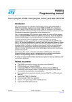
5.1
Description of the PC software
A user interface features all the functions and options to launch and control the temperature
sensing datalogger application (see Figure 22):
●
START/STOP button (see Section 5.1.1)
●
STOP button (see Section 5.1.2)
●
TRACE GRAPH button (see Section 5.1.3)
●
Dynamic view checkbox (see Section 5.1.4)
Figure 22. M24LR64-R_Datalogger_application_software home page
28/42
Doc ID 17419 Rev 1
AN3209
5.1.1
PC software
START button algorithm
In data acquisition mode, clicking the START button from the menu writes the START value
in the Status byte (see Section : System bytes) via the RF interface and starts data
acquisition. Figure 23 shows the START button algorithm.
Figure 23. START button algorithm
&!),
3END)NVENTORYCOMMAND
35##%33
4HEREISNO$ATA,OGGERIN
THEREADERFIELD
2EAD3TATUS?"YTE
9%3
3TATUS?"YTE
34!24
,OWBATTERY
MESSAGEAPPEARS
./
3WITCH3TARTBUTTONIN
STOPBUTTON
7RITE3TATUS?"YTE34!24
2EAD$ELAY?"YTE
$ELAY?"YTE
S
9%3
!UTHORIZE$YNAMICVIEW
./
3TART4IMER
!)
Doc ID 17419 Rev 1
29/42
PC software
5.1.2
AN3209
STOP button algorithm
In data acquisition mode, clicking the STOP button from the menu writes the STOP value in
the application Status byte (see Section : System bytes) via the RF interface and stops data
acquisition. Figure 24 shows the STOP button algorithm.
Figure 24. STOP button algorithm
2EAD3TATUS?"YTE
3TATUS?"YTE
34!24
9%3
,OWBATTERY
MESSAGEAPPEARS
./
7RITE3TATUS?"YTE34/0
3WITCH3TOPBUTTONIN
3TARTBUTTON
!UTHORIZE$YNAMICVIEW
3TOP4IMER
!)
5.1.3
TRACE GRAPH button algorithm
Clicking the TRACE GRAPH button from the menu downloads all the acquired temperature
values stored in the M24LR64-R memory through the RF interface, and displays a graphical
representation of these data. When the delay is set to 1 s, the window displays a checkbox
that allows the user to activate a dynamic view.
Figure 25 shows the TRACE GRAPH algorithm.
30/42
Doc ID 17419 Rev 1
AN3209
PC software
Figure 25. TRACE GRAPH algorithm
&!),
3END)NVENTORYCOMMAND
35##%33
4HEREISNO$ATA,OGGERIN
THEREADERFIELD
2EAD3TATUS?"YTE
3TATUS?"YTE
25..).'
9%3
./
2EAD$ELAY?"YTE
./
$ELAY?"YTE
S
9%3
!UTHORIZE$YNAMICVIEW
4RACEAGRAPHOFSTORED
TEMPERATURES
3WITCH4RACE'RAPHBUTTONIN
2EFRESH'RAPHBUTTON
3TART4IMER
!)
5.1.4
Timer management
When the timer function is enabled, it is executed once per second. This function is used for
graphic animations such as dynamic view, periodic thermometer refresh, display of the
number of acquisition values, and meteorological pictogram.
As an example, when the Dynamic view option box is checked and as long as the
datalogger stays in the reader field, the acquired temperature values are automatically
added to the graph each second (see Figure 26 for a description of the Timer function used
in conjunction with the Dynamic view).
Refer to UM0925 for a description of the other animations.
Doc ID 17419 Rev 1
31/42
PC software
AN3209
Figure 26. Dynamic view - timer algorithm
4IMER
&!),
2EAD.B4EMP?"YTE
4HEREISNO$ATA,OGGERIN
THEREADERFIELD
35##%33
$ISPLAYTHENUMBEROF3TORED
4EMPERATURES
2EADTHELASTACQUIRED
TEMPERATURE
7AITFORS
$ISPLAYTHELASTACQUIRED
TEMPERATURE
)S$YNAMIC
VIEW
%NABLED 9%3
./
3HOW$YNAMICVIEW#HECK"OX
UN#HECKED
$YNAMICVIEW
#HECK"OX
#HECKED
(IDE$YNAMICVIEW#HECK"OX
!DDTHELASTACQUIRED
TEMPERATURETOTHEGRAPH
!)
32/42
Doc ID 17419 Rev 1
AN3209
Temperature acquisition datalogger schematics
Appendix A
Temperature acquisition datalogger
schematics
Figure 27 and Table 9 describe the electrical schematics of the datalogger for temperature
acquisition.
Doc ID 17419 Rev 1
33/42
Temperature acquisition datalogger schematics
Figure 27. Temperature acquisition datalogger schematics
34/42
Doc ID 17419 Rev 1
AN3209
AN3209
Temperature acquisition datalogger schematics
Table 9.
Component values for schematics
Component
Quantity
Description
U1
1
M24LR64-R
U2
1
STM8L101K3
U3
1
STTS75
R1 & R2
2
19 kΩ
R3
1
10 kΩ
C1
1
100 nF
J1
1
Connector
Doc ID 17419 Rev 1
35/42
M24LR64-R RF commands
Appendix B
AN3209
M24LR64-R RF commands
The M24LR64-R_Datalogger_application_software uses the USB driver library to control
RFID readers. The library is written in Visual Basic. It is available under C:\Program
Files\M24LR64-R_Datalogger_Application\sources\M24LR64R_Datalogger_application_software or from Start > M24LR64R_Datalogger_Application > M24LR64-R_Datalogger_application_software.
B.1
Inventory
The ISO 15693 inventory command is performed by calling the
Inventory_DataLogger() function:
Function Inventory_DataLogger() As Integer
Table 10.
Inventory_DataLogger()
Function description
Prototype
Parameters
Returned
value
B.2
Inventory_DataLogger()
None
i_Result: Function status
SUCCEDDED
FAILED
Reset to Ready
The Reset to Ready ISO 15693 command is performed by calling
ResetToReadyRF_DataLogger() function:
Function ResetToReadyRF_DataLogger() As Integer
Table 11.
ResetToReadyRF_DataLogger()
Function description
Prototype
Parameters
Returned
value
36/42
ResetToReadyRF_DataLogger()
None
i_Result: Function status
SUCCEDDED
FAILED
Doc ID 17419 Rev 1
AN3209
B.3
M24LR64-R RF commands
Read single block
The Read Single Block ISO 15693 command is performed by calling the
ReadRF_single_DataLogger() function.
.
Table 12.
ReadRF_single_DataLogger()
Function description
Prototype
Parameters
B.4
Function ReadRF_single_DataLogger (lngAddLow As Long,
lngDataSize As Long, lngNbByteAddress As Long) As String
lngAddLow: address the read operation starts from
lngDataSize: number of data bytes to be read
lngNbByteAddress: number of bytes used to code the address
Returned
value
String
Example
ReadRF_single_DataLogger(0, 4, 2) returns the 4 bytes read from address
0 coded on 2 bytes.
Read Multiple Block
The Read Multiple Block ISO 15693 command is performed by calling the
ReadRF_multiple_DataLogger() function:
.
Table 13.
ReadRF_multiple_DataLogger()
Function description
Prototype
Parameters
Function ReadRF_multiple_DataLogger (lngAddLow As Long,
lngRowNumber As Long, lngDataSize As Long, lngNbByteAddress As
Long) As String
lngAddLow: address the read operation starts from
lngRowNumber: number of blocks to be read (maximum 32)
lngDataSize: number of bytes per block
lngNbByteAddress: number of bytes used to code the address
Returned
value
String
Example
ReadRF_multiple_DataLogger(0,32,4,2) returns in 32*4 bytes read from the address
0 coded on 2 bytes.
Doc ID 17419 Rev 1
37/42
M24LR64-R RF commands
B.5
AN3209
Write single block
The Write Single Block ISO 15693 command is performed calling the
ReadRF_multiple_DataLogger() function WriteSingleBlockRF_DataLogger() function:
.
Table 14.
WriteSingleBlockRF_DataLogger()
Function description
Prototype
Parameters
B.6
Function WriteSingleBlockRF_DataLogger(lngadd As Long, strData
As String, lngDataSize As Long, lngNbBytesAddress As Byte) As
Integer
lngadd: address where the data must be written
strData: String containing the data to be written
lngDataSize:number of data bytes to be written
lngNbBytesAddress: number of bytes used to code the address
Returned
value
ErrorStatus:
SUCCEEDED
FAILED
Example
WriteSingleBlockRF_DataLogger(0, Data_To_Send, 4, 2) returns SUCCEEDED if
the data write has succeeded, FAILED otherwise.
estar commands
All previous Visual Basic functions are compatible with estar readers.
38/42
Doc ID 17419 Rev 1
STTS75 I2C commands
AN3209
Appendix C
STTS75 I2C commands
The M24LR64-R_Datalogger_application_firmware uses the i2c_ee.c C library to interface
with the STTS75 temperature sensor. The library is available under C:\Program
Files\M24LR64-R_Datalogger_Application\sources\M24LR64R_Datalogger_application_firmware or from Start > M24LR64R_Datalogger_Application > M24LR64-R_Datalogger_application_firmware.
The address Byte defines the address of the STTS75 on the I2C bus. It is defined by the
SENSOR_ADDRESS global variable of the i2c_ee.c
#define SENSOR_ADDRESS
C.1
0x90
Acquire temperature
The I2C_SS_Config() function configures the STTS75 in temperature acquisition mode.
Refer to the STTS75 datasheet for a detailed description of the pointer byte and of the
corresponding registers.
.
Table 15.
I2C_SS_Config()
Function description
Prototype
Parameters
Returned
value
I2C_SS_Config (uint16_t ConfigBytes)
ConfigBytes: 2 bytes resulting from the concatenation of the Pointer byte and
Configuration byte.
Pointer byte: Bits P2 to P7 must always be set to 0. Bits P0 and P1 define the
pointer value corresponding to the register to be configured.
Configuration byte: Value to be programmed in the Configuration register. It is the
last byte of the Pointer Set Configuration Register Write frame. (see Section :
Acquire temperature). Default value is 0x00.
ErrorStatus:
SUCCEEDED
FAILED
Example
I2C_SS_Config (0x0183) configures the STTS75 to perform one temperature
acquisition with a resolution of 9 bits and store the value in the 16 bits temperature register.
where
Pointer byte = 0x01
Configuration byte = 0x83
ConfigBytes = 0x0183.
C.2
Read acquired Temperature
The I2C_SS_BufferRead() function allows to read a temperature acquisition value.
Doc ID 17419 Rev 1
39/42
STTS75 I2C commands
.
Table 16.
AN3209
I2C_SS_Config()
Function description
Prototype
I2C_SS_BufferRead(unit8_t* pBuffer, unit16_t ReadAddr,
unit8_t NumberByteToRead)
Parameters
pBuffer: pointer to the buffer containing the 2-bytes temperature data
This buffer contains the acquired temperature coded on 2 bytes (refer to Table 8:
Relationship between temperature and digital output).
pBuffer[1] and pBuffer[2] are the MSB and the LSB, respectively.
ReadAddr: Pointer byte. The Pointer byte must be set to 0x00 to access the
temperature register.
NumberByteToRead: Number of bytes to read.
Returned
value
ErrorStatus:
SUCCEEDED
FAILED
Example
I2C_SS_BufferRead(pBuffer, 0x00, 0x02) accesses the sensor temperature
register and stores the read value in pBuffer.
40/42
Doc ID 17419 Rev 1
AN3209
6
Revision history
Revision history
Table 17.
Document revision history
Date
08-Jun-2010
Revision
1
Changes
Initial release.
Doc ID 17419 Rev 1
41/42
AN3209
Please Read Carefully:
Information in this document is provided solely in connection with ST products. STMicroelectronics NV and its subsidiaries (“ST”) reserve the
right to make changes, corrections, modifications or improvements, to this document, and the products and services described herein at any
time, without notice.
All ST products are sold pursuant to ST’s terms and conditions of sale.
Purchasers are solely responsible for the choice, selection and use of the ST products and services described herein, and ST assumes no
liability whatsoever relating to the choice, selection or use of the ST products and services described herein.
No license, express or implied, by estoppel or otherwise, to any intellectual property rights is granted under this document. If any part of this
document refers to any third party products or services it shall not be deemed a license grant by ST for the use of such third party products
or services, or any intellectual property contained therein or considered as a warranty covering the use in any manner whatsoever of such
third party products or services or any intellectual property contained therein.
UNLESS OTHERWISE SET FORTH IN ST’S TERMS AND CONDITIONS OF SALE ST DISCLAIMS ANY EXPRESS OR IMPLIED
WARRANTY WITH RESPECT TO THE USE AND/OR SALE OF ST PRODUCTS INCLUDING WITHOUT LIMITATION IMPLIED
WARRANTIES OF MERCHANTABILITY, FITNESS FOR A PARTICULAR PURPOSE (AND THEIR EQUIVALENTS UNDER THE LAWS
OF ANY JURISDICTION), OR INFRINGEMENT OF ANY PATENT, COPYRIGHT OR OTHER INTELLECTUAL PROPERTY RIGHT.
UNLESS EXPRESSLY APPROVED IN WRITING BY AN AUTHORIZED ST REPRESENTATIVE, ST PRODUCTS ARE NOT
RECOMMENDED, AUTHORIZED OR WARRANTED FOR USE IN MILITARY, AIR CRAFT, SPACE, LIFE SAVING, OR LIFE SUSTAINING
APPLICATIONS, NOR IN PRODUCTS OR SYSTEMS WHERE FAILURE OR MALFUNCTION MAY RESULT IN PERSONAL INJURY,
DEATH, OR SEVERE PROPERTY OR ENVIRONMENTAL DAMAGE. ST PRODUCTS WHICH ARE NOT SPECIFIED AS "AUTOMOTIVE
GRADE" MAY ONLY BE USED IN AUTOMOTIVE APPLICATIONS AT USER’S OWN RISK.
Resale of ST products with provisions different from the statements and/or technical features set forth in this document shall immediately void
any warranty granted by ST for the ST product or service described herein and shall not create or extend in any manner whatsoever, any
liability of ST.
ST and the ST logo are trademarks or registered trademarks of ST in various countries.
Information in this document supersedes and replaces all information previously supplied.
The ST logo is a registered trademark of STMicroelectronics. All other names are the property of their respective owners.
© 2010 STMicroelectronics - All rights reserved
STMicroelectronics group of companies
Australia - Belgium - Brazil - Canada - China - Czech Republic - Finland - France - Germany - Hong Kong - India - Israel - Italy - Japan Malaysia - Malta - Morocco - Philippines - Singapore - Spain - Sweden - Switzerland - United Kingdom - United States of America
www.st.com
42/42
Doc ID 17419 Rev 1