1
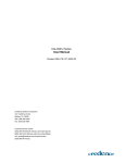
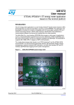
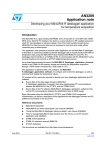
Dual Interface EEPROM
Product presentation
December 2011
Dual Interface EEPROM – Introduction
New MCU control
function
Low-power I2C
interface
RFID and NFC
compatible
RF interface
Unique Energy
Harvesting Function
High-reliability
EEPROM
Enabling a wide range of use cases…
Parameter setting
User setting profile
Usage/load information
Activation key
MANUFACTURING
&
LOGISTICS
RFID
END USER
Datalogging
Personalization
Dual
Interface
EEPROM
Factory settings
In-line calibration
Traceability
Event Log
Warranty management
Wireless pairing
SERVICING &
MAINTENANCE
Calibration
After Sales
Warranty management
RFID
Traceability
NFC
Dual Interface EEPROM - Concept
Read and write parameters
from inside (I²C) and outside (RF)
the application
Dual Interface EEPROM - How it works
Based on Passive RFID technology
Just add a 13.56 MHz inductive antenna onto your PCB
Dual Interface EEPROM
Inductive antenna
No battery needed to operate the
dual interface EEPROM in RF mode
Dual Interface EEPROM : targeted applications
Peripherals,
Communication,
Consumer Electronics
Industrial
Medical
Metering
Factory automation
•
•
•
•
•
•
•
•
•
•
•
•
Calibration
Parameter update
Diagnostics
Maintenance
Asset tracking
Activation
Parameter update
Diagnostics
Maintenance
Traceability
Asset tracking
Activation
Smart sensors,
RFID
•
•
•
•
Data loggers
Identification
Traceability
Sensors/cold chain
Dual Interface EEPROM…
New perspectives for parameters management
Wireless access
Operating data
User settings
Traceability
information
Application data
Event log
Identification data
Ideal for product
configuration
management !
Dual Interface EEPROM…
Convenient zero-power RF data download
Ideal for portable
devices such as
healthcare and
wellness products !
Pulse
Oximeter
Thermometer
Pedometer
On-The-Go
Data Download
M24LR64
Inside
Glucose
Meter
CPR card
Fitness
watch
Weight
Scale
Patient
Monitoring
Home or Hospital
Data Analysis
Dual Interface EEPROM…
Improved consumer experience
New innovative use cases
for consumer and home
appliance products !
User Manual’s URL
Usage / load information
Power consumption history
Warranty information
Date of purchase
User profile setting and reading
Model ID
Use smartphone
for data processing
and user-friendly
interface
Event recorder/temperature log
Calibration data
Dual Interface EEPROM…
Improved customer service
Static
information
Dynamic
information
RF operations working even
when device powered off !
•
•
•
•
•
•
Model ID
Serial Number
Manufacturing plant
Date code
BOM version
Firmware version
• Tamper detection information
• Incidents/defaults logs
• Tracking of critical
components
• Last maintenance records
Dual Interface EEPROM…
Enabling battery-less applications
New
M24LR16E
Innovative energy harvesting function
enabling battery-less designs !
A few mA at ~2V delivered to your
MCU and other components
Dual Interface EEPROM - benefits
Product
configuration
management
Extended
battery lifetime
Battery-less
designs
Improved
customer
service
Improved
consumer
experience
Dual Interface EEPROM conclusion
Innovation based on 2 industry-standard
protocols
Enables cost reduction and flexibility at all
product life steps
If you would like more details, go to the next slide
Product Features
M24LR64 block diagram
I²C interface
- industry standard
- 1.8-5.5V, 400kHz
VCC
64-bit UID
GND
(FactoryProgrammed and
Locked )
SCL
ISO 15693 RF interface
- industry standard
- passive RFID
technology
- high-speed mode
(up to 53 Kbit/s)
SDA
E1
I ²C
protocol
E0
AC1
AC0
64-bit Unique
Identifier
Power
management
and
PC/RF
arbitration
unit
I²C/RF
arbitration
EEPROM
64-Kbit
EEPROM
RF
protocol
Power
extraction
Password
protection
scheme
M24LR16E block diagram
External power supply
NEW!
64-bit
UID
VCC
GND
I²C interface
SCL
I²C
protocol
SDA
RF WIP_BUSY
(Digital output)
Power
management
and
PC/RF
arbitration
unit
RF WIP_BUSY
Vout
(energy harvesting from RF)
VOUT
ISO 15693
RF interface
AC1
AC0
16k-bit
EEPROM
Power
Management
Unit
RF
protocol
ST Confidential
Antenna Integration
Antenna integration
On-board
On-board inductor
Off-board or
Daughter board
I²C interface
Pros
Pros
Integrated and compact
solution
• Small footprint
• Standard component
(4.7µH)
• Small design effort
Cons
Probably less space
available on the PCB for
a large antenna. Read
range may then be
smaller
Cons
• Limited read range
• More sensitive to
orientation vs reader
antenna
Pros
• Antenna may be placed closer to
the outside of the device
• Larger antenna may be designed
• Eventually, better read ranges
• A 2-layer PCB is good enough
Cons
• Unless the antenna is connected,
the M24LR64 may not be accessed
in RF mode
Designers support – antenna design
There are other options for integrating the antenna into
your PCB. An example is « surrounding antenna »
Contact your ST technical support for specific antenna
design support
Surrounding
Antenna
Designers support - antenna integration
ST provides documents helping customers design
the antenna by themselves
Application note
AN2972 Designing an antenna for the M24LR64-R dual interface
AN3178 Using a surface-mount inductor as M24LR64-R antenna
Software
Executable meant for computing a 13.56 MHz antenna
Reference designs
ANT1-M24LR16E
ROBOT-M24LR16E-A
ANT2-M24LR16E
ANTx-M24LR-A
Back to
Main Menu
RF reader-writers
4 types of RF reader-writers
Commercial ISO15693 RFID reader-writers,
available through partners
ST’s 13.56MHz transceiver IC for embedded RF
reader-writer
Mobile phones with ISO15693 capable NFC
function
ST’s evaluation kits for evaluation / development
Commercial RF reader-writers
ISO15693 standard at 13.56 MHz - Firmware upgrade might be required
Exists in various form factors providing wide range of price and performance
RFID reader
Pad/desktop antenna
Handheld reader
Paddle reader
Tunnel station
Conveyor tunnel reader
Gate antenna
Check out the video at www/st/com/edemoroom
(Play « Dual Interface EEPROM RF technology »)
CF module
Commercial RF reader-writer partners
ST is developing a network of reader partners, which are
supporting the M24LR64.
More information available at www.st.com/dualeeprom
Embedded reader-writer: CR95HF chip
ST ISO15693 products will be supported by the CR95HF
with
Software libraries
Reference design
Application notes
M24LR64, M24LR16E
64-Kbit and 16-Kbit
Dual I/F EEPROM
LRi1K, LRi2K,
LRiS2K
UART
Host
controller
ISO15693
Memory
Library
Optional
AES
Encryption
Library
(e.g. STM32
UM0586)
1 and 2-Kbit ISO15693
LRiS64K
SPI
64-Kbit ISO15693 w/
password protection
Other ISO15693
Support of other
ISO15693 devices
Design your own embedded RF reader-writer
CR95HF with Dual Interface EEPROM
Enabling innovative interactive data exchange
Main-unit or reader-writer
MCU
CR95HF
SPI
Memory
with Dual Access
New Application
MCU
M24LRxx
I²C
Display
Touch keys
Sensors
CR95HF technical support
CR95HF drivers (ANSI C)
Schematics and gerber files
- Source code CR95HF drivers v1.0.rar
- Application note AN3355
- Schematics (0017031-B-SCM.pdf)
- Gerber files (0017031-B-Gerber.zip)
PC demonstration software
- M24LRxx Application Software 2.0.zip
Antenna design guidelines
-Application note AN3394
-Antenna design simplified basic tool
DEMO-CR95HF-A
CR95HF ordering information
CR 95 HF-VMD5T
Product Type
Wired
Access
Operating
Voltage
Frequency
Band
Package
CR=Contactless reader IC
HF=High Frequency
(13.56MHz)
95=SPI + UART
V: 2.7V-3.3V
Tape
&
Reel
Operating
Temperature
5: - 25C / +85C
NFC: mobile phones as RF reader-writers
Compatible with ISO15693-capable NFC phones
Dual EE NFC Android App
Works with DATALOG-M24LR-A
reference design
• Dual EE app on the Android market
• Source code at www.st.com/dualeeprom
Nfc-Vreader Android App
M24LR64, M24LR16E
64-Kbit and 16-Kbit
Dual I/F EEPROM
LRi1K, LRi2K,
LRiS2K
1 and 2-Kbit
LRiS64K
64-Kbit w/ password
protection
In development
• Reader-writer application
• Works with ISO15693 products
• Contact your local sales team for
support
Back to
Main Menu
Evaluation Kits
Designers support
Development kit – “DEVKIT-M24LR-A’’
Pad antenna
ANT1-M24LR-A
RFID
reader
I²C
programmer
NB: SDK dll source files available for Windows for free. Charges
apply for other platforms such as .Net, Java,…
ANT2-M24LR-A
ANT3-M24LR-A
Designers support
Starter kit – “STARTKIT-M24LR-A’’
ANT1-M24LR-A
ANT2-M24LR-A
NB: basic dll source files available for Windows only
ANT3-M24LR-A
Designers support
Evaluation kits summary
Purpose
RF operating distance
RF and I²C communication
speed
RF capabilities
Software
Starter kit
Development kit
Evaluation, proof-of-concept
Development, advanced evaluation
Up to 8 cm*
Up to 40 cm*
Slow
Fast
read 64k-bit : 1’24’’
write 64k-bit : 5’34’’
read 64k-bit : 0’08’’
write 64k-bit : 0’31’’
1 tag at a time
Multi-tag capability
Windows dll source code
Windows SDK for free
(others platforms SDK with charge)
FEIG download access code available
Ordering information
STARTKIT-M24LR-A
DEVKIT-M24LR-A
Reference Designs
A wide range of antenna boards…
Contact your local ST sales team for more details
M24LR64-R Datalogger reference design
DATALOG-M24LR-A is a complete reference design with
Hardware design (including antenna design)
MCU firmware (STM8L)
PC software
Turn-key data logging design
DATALOG-M24LR-A
M24LR64-R Datalogger reference design
Demonstrates the use of the M24LR64 in a data logging
application (medical, industrial sensors, …)
helps customers get started with their RFID-enabled
datalogger design
Can be extended to also sense shocks/vibrations, pressure,
light…
DATALOG-M24LR-A
Demonstration
software
Supporting
material
M24LR64-R Datalogger supporting material
AN3209 Application note
Developing your M24LR64-R datalogger application for
temperature acquisition
UM0925 User Manual
Using the M24LR64-R datalogger reference design
.zip
Source
code
Source
code
Gerber files for M24LR64-R datalogger
Firmware for the STM8L101 Microcontroller
Demonstration PC software
The M24LR64-R Datalogger supporting material can be downloaded at
www.st.com/dualeeprom
Ordering Information
Dual Interface EEPROM
Nomenclature for package delivery
M24 LR 16E-RMN6T/2
Serial Interface RF Interface
Type
Type
Memory
Size
Operating
Voltage
R: 1.8V-5.5V
Package
M24 : I2C interface
in user K bits
Internal Tuning
Tape
Capacitance
&
Reel
2: 27.5pF
Operating
Temperature
E: energy harvesting
LR: Long range / 13.56MHz - ISO 15693
6: - 40C / +85C
Dual Interface EEPROM
Nomenclature for die delivery
M24 LR 64-RS185/2
Serial Interface
Type
RF Interface
Type
Memory
Size
Operating
Voltage
Internal Tuning
Capacitance
R: 1.8V-5.5V
Package
M24 : I2C interface
2: 27.5pF
in user K bits
S/Z: Sawn wafer on metallic frame and
UV tape (inkless/inked)
1: wafer orientation in frame
8: wafer size in inches
LR: Long range / 13.56MHz - ISO 15693
5: wafer thickness = 140µm
M24LR64-RS185/2 – die format
M24LR64 chip in die form (meant for
wire bonding technology)
Ultra thin: 140µm thickness +/-10µm
Sawn wafers on UV tape and 8’’ ring
S version: bad chips identified by electronic wafermap (« STIF » format)
provided by ST
Z version: bad chips identified with ink dots on wafer
6 months lifetime @25 degC (UV tape limited)
Production Minimum Ordering Quantity (MOQ) is 5 wafers, i.e.
approximately 42.5ku
See TN0185 for complete die form delivery information
Back to
Main Menu