1
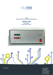
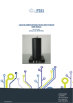
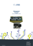
TL 2000 Integrated System for thermoluminescence measurements USER MANUAL Rel.01.01.0001 (Hardware code: TL 2000) 1 TL 2000 USER MANUAL _____________________________ Information provided in this manual is property of IPSES S.r.l. and must be considered and treated as confidential. This publication can only be reproduced, transmitted, transcribed or translated into any human or computer language with the written consent of IPSES S.r.l. Information in this documentation has been carefully checked and is believed to be accurate as of the date of publication; however, no responsibility is assumed of inaccuracies. IPSES will not be liable for any consequential or incidental damages arising from reliance on the accuracy of this documentation. Information contained in this manual is subject to change without notice and does not represent a commitment on the part of IPSES. The design of this instrument is subject to continue development and improvement. Consequently, the equipment associated to this document may incorporate minor changes in detail from the information hereafter provided. All brand or product names are trademarks or registered trademarks of their respective holders. This manual in English is the original version. Printed in Italy Copyright 2009-2015IPSES S.r.l. All rights reserved. 2 IPSES S.r.l. Via Suor Lazzarotto, 10 - 20020 Cesate (MI) - ITALY Tel. (+39) 02 39449519 Fax (+39) 02 700403170 http://www.ipses.com e-mail [email protected] TL 2000 USER MANUAL GUARANTEE IPSES warrants to the end-user in accordance with the following provisions that its branded hardware products, purchased by the end-user from IPSES company or an authorized IPSES distributor will be free from defects in materials, workmanship and design affecting normal use, for a period of one year as of the original purchase date. Products for which proper claims are made will, at IPSES’s option, be repaired or replaced at IPSES’s expense1. Exclusions This Guarantee does not apply to defects resulting from: improper or inadequate installation, use or maintenance; actions or modifications by unauthorized third parties or the end-user; accidental or wilful damage or normal wear and tear. Making a claim Claims must be made by contacting IPSES office within the guarantee period. Please, contact: IPSES S.r.l. - Via Suor Lazzarotto, 10 - 20020 Cesate (MI) Italy Tel. (+39) 02 39449519 – (+39) 02 320629547 Fax (+39) 02 700403170 http://www.ipses.com - e-mail: [email protected] Limitation and Statutory Rights IPSES makes no other warranty, guarantee or like statement other than as explicitly stated above and this Guarantee is given in place of all other guarantees whatsoever, to the fullest extent permitted by law. In the absence of applicable legislation, this Guarantee will be the end-user’s sole and exclusive remedy against IPSES. General Provisions IPSES makes no express warranties or conditions beyond those stated in this warranty statement. IPSES disclaims all other warranties and conditions, express or implied, including without limitation implied warranties and conditions of merchantability and fitness for a particular purpose. IPSES’s responsibility for malfunctions and defects in hardware is limited to repair and replacement as set forth in this warranty statement. IPSES does not accept liability beyond the remedies set forth in this warranty statement or liability for incidental or consequential damages, including without limitation any liability for products not being available for use or for lost data or software. 1 With the exclusion of shipping costs for and from IPSES’s development office. 3 IPSES S.r.l. Via Suor Lazzarotto, 10 - 20020 Cesate (MI) - ITALY Tel. (+39) 02 39449519 Fax (+39) 02 700403170 http://www.ipses.com e-mail [email protected] TL 2000 USER MANUAL WARNING! ELECTRICAL DEVICES COULD DAMAGE EQUIPMENT OR PROPERTY OR CAUSE PERSONAL INJURY This guide contains instructions and technical features of the TL 2000. Read with attention before attempting to install. It is the responsibility of the technician to undertake all the safety rules provided by the law during the installation and the use of this device. For any information which is not contained in this guide, please contact: IPSES S.r.l. - Via Suor Lazzarotto, 10 - 20020 Cesate (MI) Italy Tel. (+39) 02 39449519 – (+39) 02 320629547 Fax (+39) 02 700403170 http://www.ipses.com - e-mail: [email protected] 4 IPSES S.r.l. Via Suor Lazzarotto, 10 - 20020 Cesate (MI) - ITALY Tel. (+39) 02 39449519 Fax (+39) 02 700403170 http://www.ipses.com e-mail [email protected] TL 2000 USER MANUAL TABLE OF CONTENTS REVISION HISTORY .......................................................................................................................................................... 6 1. DESCRIPTION................................................................................................................................................................ 7 2. THE TL 2000 THERMOREGULATION UNIT.................................................................................................................. 7 3. TL2000 FRONT PANEL .................................................................................................................................................. 8 5. VACUUM OVEN ........................................................................................................................................................... 11 6. TECHNICAL FEATURES OF THE TL2000 SYSTEM ................................................................................................... 13 7. SPECTRAL RESPONSE OF THE OPTICAL FILTERS ................................................................................................ 13 8. CONNECTIONS AND INSTALLATION OF THE SYSTEM ........................................................................................... 15 9. PARAMETERS SETUP ................................................................................................................................................ 17 10. EXECUTION OF A HEATING CYCLE BY MANUAL CONTROL ................................................................................ 18 11. OPTIMIZATION OF THE P-I-D CONTROL LOOP ...................................................................................................... 18 12. REMOTE CONTROL .................................................................................................................................................. 19 13. NOTES ON THE INSTALLATION OF TL2000 SYSTEM ............................................................................................ 22 14. TL2000 CONTROL MANAGER SOFTWARE ............................................................................................................. 22 15. MAINTENANCE .......................................................................................................................................................... 31 16. TECHNICAL SPECIFICATIONS ................................................................................................................................. 32 CONTACTS ...................................................................................................................................................................... 33 SUPPORT INFORMATION ............................................................................................................................................... 34 PROBLEM REPORT......................................................................................................................................................... 34 ENGINEERING PROBLEM REPORT............................................................................................................................... 35 5 IPSES S.r.l. Via Suor Lazzarotto, 10 - 20020 Cesate (MI) - ITALY Tel. (+39) 02 39449519 Fax (+39) 02 700403170 http://www.ipses.com e-mail [email protected] TL 2000 USER MANUAL REVISION HISTORY Manual revision history Revision/ Date 01.00.0000 January, 2007 01.00.0001 October, 2009 01.01.0000 June, 2011 01.01.0001 June 2015 Change description Author First version Released Mancuso C. Updated contacts, other minor changes Mancuso C. Updated software functions Mancuso C. Update document layout Bottaccioli M. 6 IPSES S.r.l. Via Suor Lazzarotto, 10 - 20020 Cesate (MI) - ITALY Tel. (+39) 02 39449519 Fax (+39) 02 700403170 http://www.ipses.com e-mail [email protected] TL 2000 USER MANUAL 1. DESCRIPTION The TL 2000 control system is conceived and built as an integrated system to perform thermoluminescence analyses. The system is made by: An accurate and repetitive TL2000 thermoregulation unit to control the heating ramp and to acquire photodetection signals A vacuum oven to heat the sample in a controlled atmosphere A photo-detection unit constituted by a signal processing circuit, a sensitive photomultiplier operating in photon-counting mode, and a high-voltage power supply mod. HiVo. The unit acquires the thermoluminescence signal from the sample as a function of the rising temperature (glow curve). 2. THE TL 2000 THERMOREGULATION UNIT 7 IPSES S.r.l. Via Suor Lazzarotto, 10 - 20020 Cesate (MI) - ITALY Tel. (+39) 02 39449519 Fax (+39) 02 700403170 http://www.ipses.com e-mail [email protected] TL 2000 USER MANUAL The integrated unit for thermoluminescence measurements TL2000 is designed to produce very accurate and repetitive heating profiles to allow the acquisition of the light emitted by the heated sample as a function of the temperature. The operation of the instrument can be controlled by a personal computer equipped with an IEEE-488 (GPIB) parallel interface: a software to control the heating profile and collect and review the data is supplied as part of the system2. 3. TL2000 FRONT PANEL LCD Display 2 See Software section at chapter 15 of this manual. 8 IPSES S.r.l. Via Suor Lazzarotto, 10 - 20020 Cesate (MI) - ITALY Tel. (+39) 02 39449519 Fax (+39) 02 700403170 http://www.ipses.com e-mail [email protected] TL 2000 USER MANUAL TL 2000 THERMOLUMINESCENCE CONTROL UNIT START STOP ENTER SETUP UP DOWN ENTER ESC SYSTEM POWER 0 1 By IPSES S.r.l. 2 3 4 5 1 Function SETUP Function 1 Power switch 2 START UP 3 STOP DOWN 4 ENTER ENTER 5 SETUP ESC 9 IPSES S.r.l. Via Suor Lazzarotto, 10 - 20020 Cesate (MI) - ITALY Tel. (+39) 02 39449519 Fax (+39) 02 700403170 http://www.ipses.com e-mail [email protected] TL 2000 USER MANUAL 4. TL2000 REAR PANEL 6 8 7 SIGNAL INPUT TEST OUTPUT Serial Number: PREAMP POWER By IPSES S 230 Vac IEEE 488 C C 9 6 10 11 12 Input 13 threshold 14 adjustment 7 Signal Input 8 Test output 9 Mains power input 10 Preamplifier power supply output 11 GPIB interface (to control PC) 12 Thermocouple input 13 Fan 14 Oven power output 10 IPSES S.r.l. Via Suor Lazzarotto, 10 - 20020 Cesate (MI) - ITALY Tel. (+39) 02 39449519 Fax (+39) 02 700403170 http://www.ipses.com e-mail [email protected] TL 2000 USER MANUAL 5. VACUUM OVEN The vacuum TL oven is designed to heat the samples during the thermoluminescence analyses. Heating is achieved through a metal strip that supports the sample during the measurement. The oven atmosphere is controlled by using a vacuum root pump to remove the air and replace it with pure nitrogen from a supply line. The following images show the vacuum oven parts. An interlock switch disables the high voltage supply to the PM tube when the housing is not properly mounted on the top of the oven to prevent any possible damage to the PM tube. Interlock switch PM tube housing Inner pressure indicator Nitrogen diffuser Thermocouple connector Connector to nitrogen supply line Connector vacuum pump to 11 IPSES S.r.l. Via Suor Lazzarotto, 10 - 20020 Cesate (MI) - ITALY Tel. (+39) 02 39449519 Fax (+39) 02 700403170 http://www.ipses.com e-mail [email protected] TL 2000 USER MANUAL Socket for the thermocouple Sample holder Heating strip Top view Bottom view The TL oven is equipped with an optional optical filter to be inserted when measuring high yield samples (the filter is a BG12 type with the same spectral response as the filter mounted inside the PM tube housing. See section 8 for details). Filter holding plate Filter To insert the filter, first put its holding plate inside the oven as shown in the picture below, and then place the filter in the hole. To remove the filter, use a small suction cup to take it away from the oven, and then take the plate by the hole in the center, as shown in the picture above. 12 IPSES S.r.l. Via Suor Lazzarotto, 10 - 20020 Cesate (MI) - ITALY Tel. (+39) 02 39449519 Fax (+39) 02 700403170 http://www.ipses.com e-mail [email protected] TL 2000 USER MANUAL 6. TECHNICAL FEATURES OF THE TL2000 SYSTEM Sample heating is obtained through a heating resistive element. The temperature is measured through a type-K thermocouple (heating resistive element and thermocouple are provided with the unit). The control of the power supplied to the heating element is achieved by the use of a PID loop: the error signal, obtained as difference between the reference temperature at a given time t and the actual temperature measured by the thermocouple, is differentiated and integrated. The three components (Proportional, Integral and Differential) are independently amplified (the gain values can be adjusted by the user). The accuracy of the heating profile can be minimized by adjusting the gains of the PID control loop. Different installation conditions (length of the oven cables, operating pressure, dimension and type of the sample) can require an adjustment of the default gain settings. The measure of the intensity of the light emitted by the sample during the heating (glow curve) is achieved by photon counting: a proper PM tube suitable for this operating mode (low dark current, high focusing) must be used. Optionally, the PM tube can be purchased as part of the TL2000 control system. The overall quality of the measurements performed by the system is affected by the correct choice of the PM tube. When the device is connected to a personal computer, it is possible to control the operation of the TL2000 by using a specific software application. The communication between the device and the control computer is achieved through an IEEE-488 parallel interface (GIPB) with a proprietary protocol as described in section 13. Besides, it is possible to control the operation of the TL2000 unit by using the local keys on the frontal panel of the unit. 7. SPECTRAL RESPONSE OF THE OPTICAL FILTERS Inside the PM tube housing there are two circular filters with a diameter of 50 mm and a thickness of 4 mm. The purpose of these filters is to minimize the background due to the dark body emission and achieve the best match to the spectral sensitivity of the photocatode. Besides, a consistent removal of the IR component protects the PM tube from any possible accidental damage. The two filters are: BG12 Filter (pass band filter) KG5 Filter (high temperature resistant pass band filter) 7.1 Features of the BG12 filter. The BG12 filter has a blue color and, when necessary, can be removed from the housing by unscrewing its lower flange. The following graph shows the spectral transmission response of the BG12 filter 13 IPSES S.r.l. Via Suor Lazzarotto, 10 - 20020 Cesate (MI) - ITALY Tel. (+39) 02 39449519 Fax (+39) 02 700403170 http://www.ipses.com e-mail [email protected] TL 2000 USER MANUAL 7.2 Features of the KG5 filter. This filter allows visible light to pass while it absorbs infrared light. Besides, it is high temperature resistant. It has no color and it cannot be removed from the housing, because it is also part of the vacuum seal of the oven. The following graph shows the spectral transmission response of the KG5 filter: 14 IPSES S.r.l. Via Suor Lazzarotto, 10 - 20020 Cesate (MI) - ITALY Tel. (+39) 02 39449519 Fax (+39) 02 700403170 http://www.ipses.com e-mail [email protected] TL 2000 USER MANUAL 8. CONNECTIONS AND INSTALLATION OF THE SYSTEM The TL2000 system needs to be installed in a proper dark room equipped with electrical connecting plugs, nitrogen connections, vacuum pump with its connections and ventilation3. A B Nitrogen diffuser Terminals of the heating strip. Thermocouple feedthrough cable Thermocouple connector 3 It is the responsibility of the end user to comply with all the safety rules provided by law for the installation and the use of the laboratory. Besides, the end user needs to obtain the necessary authorization to hold radiation sources for reference measures. These radiation sources are not provided with the TL2000 system. 15 IPSES S.r.l. Via Suor Lazzarotto, 10 - 20020 Cesate (MI) - ITALY Tel. (+39) 02 39449519 Fax (+39) 02 700403170 http://www.ipses.com e-mail [email protected] TL 2000 USER MANUAL 8.1 Installation of the vacuum oven Remove the oven form the packaging. Mount the thermocouple for the measure of the heating strip temperature: for this, insert the thermocouple tip in its feedthrough flange after having loosened the locknut, then mount it in the proper socket under the heating strip. To facilitate the operation, you can remove the heating strip from its terminals, unscrewing the two screws which fix it. Be careful in handling the thermocouple, because the capillary pipe is mechanically fragile. After having inserted the thermocouple and mounted back the heating strip (locking the screws), gently tighten the feedthrough locknut by hands: vacuum tight is guaranteed. Connect the two power supply cables fixing them in the proper connections on the bottom of the oven: use a proper wrench to close the nuts. Place the oven in the final position and connect the joint for the suction pipe (with its needle valve to control the flow) on one of the two flange connectors type DN16KF (indicated with B in the picture at the previous page). Mount on the other flange the pipe for nitrogen refill with its o-ring (indicated with A in the picture page 15). Check that the nitrogen line is connected to the flange close to the diffuser inside the oven (see the picture at page 15). Complete the connection to the vacuum pump using connectors and flexible vacuum pipes4. Mount the filter to remove oil on the drain pipe of the vacuum pump (as indicated in the instruction of the pump). Follow the instructions of the vacuum pump manufacturer for any other detail. 8.2 Installation of the photomultiplier tube (PMT) 4 Flexible connection pipes are also not included in the TL system package and should be purchased as required by the installation characteristics. 16 IPSES S.r.l. Via Suor Lazzarotto, 10 - 20020 Cesate (MI) - ITALY Tel. (+39) 02 39449519 Fax (+39) 02 700403170 http://www.ipses.com e-mail [email protected] TL 2000 USER MANUAL Open the holder of the photomultiplier tube disassembling the bayonet cap. Take off the PM tube from the packaging, remove the protecting film on the photocathode and insert it in the base integral with the cap. Assemble the magnetic screen around the tube and connect it electrically to the plug provided next to the base. Close the holder and mount it over the oven. When necessary, insert the supplied IR filter between the holder and the oven. Mount the signal preamplifier directly on the output BNC connector present on the PMT holder. Complete the electrical connections by connecting the high voltage cable (BNC HV) to the High voltage power supply HiVo, and the interlock on the auxiliary connector to the oven switch. 8.3 Connection of the control unit. Remove, if present, the protection resistance between the oven output terminals of the control unit; connect the power cables for the heating strip closing them, using a proper wrench, inside the terminals on the back of the control unit. To improve the performance, excess power cable length should be avoided. Complete the electrical connections using the cables supplied with the unit: For the thermocouple, use the compensation cable toward the connector n. 12 shown in the picture at page 11 For the preamplifier output, use the cable BNC/BNC toward the connector n. 7 in the in the picture at page 11 For the preamplifier power supply use the DB 9 cable toward the connector shown as n. 10 in the in the picture at page 11 For the GPIB, use the IEEE488 cable toward the connector shown as n. 11 in the in the picture at page 11 Use the cable to plug in the mains power. Remember power supply is 230 Vca Now the unit can be powered on: the display on the front panel will show the start up logo and then the current values of the sample temperature and the PM tube photon counting rate. 9. PARAMETERS SETUP Working parameters of the unit (gains of PID, parameters for the interface, maximum temperature reachable, maximum during of the heating cycle) can be set by the user, pressing the SETUP key (n. 5 at page 9) on the front panel. On the display the present working parameter values will show; it is possible to pass to another parameter pressing the ENTER key (n. 4 at page 9). To change the parameter value, press the UP Key (n. 2 at page 9) to increase the value and the DOWN key (n. 3 at page 9) to decrease it. Keeping pressing UP or DOWN keys more than half a second, the changing of the values will be faster. When the selected value is reached, press the ENTER key to confirm it, then pass to the following parameter to be set up. When all parameters are correctly set up, press again the SETUP key to exit setup function. Setup function is disabled during the performing of a heating cycle. The value of the parameters is stored in a non-volatile memory, so that when the system is powered on, it will be set on the last set up parameters. On the rear panel of the thermoregulation unit, there is the adjustable knob to set the threshold of the photomultiplier discriminator (see image at page 10 and here below). Through the knob it is possible to regulate the sensibility of the photomultiplier in detecting light, setting the values from 0 (maximum of sensibility) to 10 (minimum of sensibility). A security lock on the knob allows to stop the rotation once the value is selected. 17 IPSES S.r.l. Via Suor Lazzarotto, 10 - 20020 Cesate (MI) - ITALY Tel. (+39) 02 39449519 Fax (+39) 02 700403170 http://www.ipses.com e-mail [email protected] TL 2000 USER MANUAL Security lock to stop the rotation of the knob adjustable knob Usually, the optimum threshold value is the one that gives a count rate of about 100 cps when no heating is in progress. When switching on the device, verify the count rate: if it is very different from the optimum one, adjust the discriminator threshold to restore the optimal count rate. 10. EXECUTION OF A HEATING CYCLE BY MANUAL CONTROL To start a heating cycle, press the START key: the values for the working parameter of the cycle will be requested (heating rate in degree/s and temperature at the end of the cycle); then the heating will start. To set up the value of working parameters, follow the instructions outlined in section 10, using the START, STOP and ENTER keys. Clicking the SETUP key will cancel the operation. When the temperature of end cycle is reached, the system will stop the heating. The heating cycle can be stopped at any time by pressing the STOP key. BE CAREFUL: even if the unit is not supplying any current because the heating cycle was stopped, the heating strip will remain at a high temperature for a long time and can be dangerous in case of an accidental contact: check the temperature on the display before attempting to handle the heating strip or any element in contact with it. 11. OPTIMIZATION OF THE P-I-D CONTROL LOOP The adjustment of the P-I-D gains for the three components (Proportional, Integral and Differential) allows optimizing the behavior of the unit so to have a minimum error between the theoretical and the real heating profile. If the heating system (strip, cables, working atmosphere) changes or if user is analyzing samples which have a very different thermal capacity, the gain values need to be adjusted. We suggest to follow the procedure listed below: Set to 1 the I and D components, then increase the gain of the P component until the heating is effective up to the end temperature of the desired ramp Increase the D gain to minimize the fluctuations and ringing of the temperature Increase the I gain to minimize the temperature error Repeat the adjustments a few times until the results are satisfactory Note: an l gain set too high can cause fluctuations of the temperature which have a progressive increase of excursion and period (minutes); a high D gain can cause instability of a shorter period (seconds) and an irregular period. 18 IPSES S.r.l. Via Suor Lazzarotto, 10 - 20020 Cesate (MI) - ITALY Tel. (+39) 02 39449519 Fax (+39) 02 700403170 http://www.ipses.com e-mail [email protected] TL 2000 USER MANUAL 12. REMOTE CONTROL The TL2000 unit can be remotely controlled by a personal computer connected to the parallel interface GPIB on the unit. The GPIB port is configured as following: programmable address Supported functions: talker, listener, SeriaPoll e ParallelPoll The command strings are in ASCII code, terminated with <E 01> (no specific terminator characters). The thermoregulation unit acts as a slave device: the unit sends messages only in response to a specific request. The command syntax is listed below: UO Status request Answer: xx[,yy] xx is the coded value (in hexadecimal) in two digits of a 8-bit integer which represents the status of the unit. The bits of this number have the following meaning: bit position description 7 Error 6 SRQ activated 5 not used 4 not used 3 not used 2 not used 1 1 = heating in progress 0 1 = unit ready When the bit 7 (Error) is high, then a yy error code is added to the status byte; the request of the status will reset any error condition. The error codes are listed below: 01 Syntax error 02 Illegal command 03 Invalid parameter value 04 Overrange of the measure in progress 05 Overheating of the heating strip 06 Thermocouple not connected or out of order 07 Thermoregulator out of order or wrong connection (Time out during the heating) 08 Internal overtemperature 09 Invalid internal configuration data Besides, the status is also the byte returned by the execution of a SeRialPoll on the GPIB interface. A ServiceReQuest is generated every time an error condition occurs and at the end of a heating process. The condition of ServiceReQuest, indicated by the SRQ bit in the status byte, is automatically reset when the first SeRialPoll is executed. Besides, sending a SelectiveDeviceClear will force the unit to execute a PowerOn Reset, stopping immediately any heating cycle or acquisition in progress. 19 IPSES S.r.l. Via Suor Lazzarotto, 10 - 20020 Cesate (MI) - ITALY Tel. (+39) 02 39449519 Fax (+39) 02 700403170 http://www.ipses.com e-mail [email protected] TL 2000 USER MANUAL ?1 Requests of the temperature ttt.t ttt.t is the temperature centigrade degrees of the RO,rr.r Sets the rise a rr.r degrees/second of the Answer: heating element in ramp at rate heating Answer: none RO, ? Requests the current value of the rise rate of the heating ramp. rr.r rr.r is the degrees/second GO,tt.t Starts the heating using the set rate from the current temperature up to the tt.t temperature; once the tt.t temperature is reached, the heating stops and temperature decays naturally. Answer: current value of the rise rate in Answer: none KO Stops immediately any heating in progress Answer: none Sn,pp.p Sets the n parameter to the pp.p value; the control unit stores in its novolatile memory (E2PROM) some parameters. By this command it is possible to change the value of these parameters. The identification code of the parameter is listed below: Code 0 1 2 4 6 7 8 9 Description P gain of the control loop l gain of the control loop D gain of the control loop Maximum length of a heating cycle (hours); if is 0, this control is disabled GPIB address (only for reading) Maximum absolute working temperature (degrees Celsius) Rise temperature rate (degrees Celsius per second) Ending temperature of a cycle (degrees Celsius) Sn, ? Requests the value of the n parameter; the identification code of the parameter is the one decribed for the previous command. 20 IPSES S.r.l. Via Suor Lazzarotto, 10 - 20020 Cesate (MI) - ITALY Tel. (+39) 02 39449519 Fax (+39) 02 700403170 http://www.ipses.com e-mail [email protected] TL 2000 USER MANUAL Answer: pp.p pp.p is the current value of the n parameter expressed in the proper unit of measure. 21 IPSES S.r.l. Via Suor Lazzarotto, 10 - 20020 Cesate (MI) - ITALY Tel. (+39) 02 39449519 Fax (+39) 02 700403170 http://www.ipses.com e-mail [email protected] TL 2000 USER MANUAL 13. NOTES ON THE INSTALLATION OF TL2000 SYSTEM Installation of the software and the GPIB interface System requirements The minimum computer requirements to manage the TL2000 system are: Pentium 1GHz or higher microprocessor 256 MB RAM memory minimum 300 MB free space on the system hard disk An available slot PCI for the GPIB interface GPIB interface software driver and utility (CD-ROM) Operating system Windows 98/Xp/Me/2000 Installation of the GPIB card When the computer is powered down (power supply cable unplugged), open the computer and install the PCI-GPIB card supplied with the system. See the user manual of your PC about instructions on new cards installation. Be sure that the GPIB card is well inserted in the PCI connector and its front panel is correctly fixed to the computer case. Close the computer and restart it. Then, install the software to manage the GPIB interface which is supplied with the card on CD-ROM. Follow the guided installation procedure, choosing the suggested options. For further details, see the manual supplied with the GPIB interface card. When the installation is finished, restart the PC to make the changing to the configuration effective. It is highly recommended to execute the diagnostic software which is included in the 'NI 488.2 Software for ...' group, in order to verify that the hardware and the software are correctly installed and that there are no conflicts with other system resources. Installation of the TL2000 Control Manager software Insert the TL2000 Control Manager CD-ROM inside the CD unit of the PC and start the installation. Follow the instructions of the installation software. 14. TL2000 CONTROL MANAGER SOFTWARE TL2000 Control Manager allows acquiring, in a very intuitive way, measures from the TL2000 system. Once the software application is started, the screen appears as shown in the following page. 22 IPSES S.r.l. Via Suor Lazzarotto, 10 - 20020 Cesate (MI) - ITALY Tel. (+39) 02 39449519 Fax (+39) 02 700403170 http://www.ipses.com e-mail [email protected] TL 2000 USER MANUAL Measure commands Info: gives information on the selected curve Start: starts a new measure Quit: quits the TL2000 Control Manager program Save: saves the current measure to a disk file Load: loads a measure from disk Unload: unloads a measure LIN/LOG: changes the curve scale from linear to logarithmic and back GLOW: shows or hides the measure glow curve RAMP: shows or hides the temperature ramp curve Full Screen: allows viewing the measure windows in full screen Temperature value of the current cursor position 23 IPSES S.r.l. Via Suor Lazzarotto, 10 - 20020 Cesate (MI) - ITALY Tel. (+39) 02 39449519 Fax (+39) 02 700403170 http://www.ipses.com e-mail [email protected] TL 2000 USER MANUAL Screen showing the measured glow curve Temperature value of the current cursor position Screen showing the temperature ramp 24 IPSES S.r.l. Via Suor Lazzarotto, 10 - 20020 Cesate (MI) - ITALY Tel. (+39) 02 39449519 Fax (+39) 02 700403170 http://www.ipses.com e-mail [email protected] TL 2000 USER MANUAL Positioning and frame selection Cursors: On screens displaying the glow curve and the heating ramp, two kind of cursors are available: A yellow cross shape cursor, as shown in the pictures below: This cursor can be moved either along the glow curve and the heating ramp. When you move the cursor, also the relevant cursor in the other screen will be positioned in the other graph at that point, allowing precisely association between photon emission and temperature at the selected point The left window will indicate the exact temperature in Celsius degrees corresponding to the position of the cursor on the graph. 25 IPSES S.r.l. Via Suor Lazzarotto, 10 - 20020 Cesate (MI) - ITALY Tel. (+39) 02 39449519 Fax (+39) 02 700403170 http://www.ipses.com e-mail [email protected] TL 2000 USER MANUAL Two white cursors for frame selection, as shown in the pictures below: After selecting the desired frame, both on the heating ramp or on photon emission glow curve, on the other graph the corresponding frame will be automatically displayed. The Zoom button allows you to enlarge and view only the selected frame, while the restore button will restore back to default display settings (see next page for descriptions of these functions): 26 IPSES S.r.l. Via Suor Lazzarotto, 10 - 20020 Cesate (MI) - ITALY Tel. (+39) 02 39449519 Fax (+39) 02 700403170 http://www.ipses.com e-mail [email protected] TL 2000 USER MANUAL Window showing the folder where the measure glows are saved Zoom in: allows zooming in the curve window Zoom out: allows zooming out the curve window Restore: allows restoring the default vision without zoom On the right there is a window that displays the current folder name where curves are loaded from or where the curves are saved. The TL2000 software manager automatically installs a folder called demo measure containing three demo glow curves that can be used to become familiar with advanced software features explained in the following pages. 27 IPSES S.r.l. Via Suor Lazzarotto, 10 - 20020 Cesate (MI) - ITALY Tel. (+39) 02 39449519 Fax (+39) 02 700403170 http://www.ipses.com e-mail [email protected] TL 2000 USER MANUAL Menu bar Measure Opening the Measure from the menu bar, the following commands will appear: Start measure: starts a new measure Setup measure: trough this command it is possible to set up the measure parameters. It is possible to set up the values of the starting and ending ramp temperatures in Celsius degrees, the rise rate of the temperature in Celsius degrees per second and the acquisition rate in seconds. System configuration: gives information on the measure setup and the GPIB interface configuration Quit: allows quitting the program. Disk I/O Opening the Disk I/O from the menu bar, the following commands will appear: Load measure: loads a saved measure from disk Unload measure: unloads a measure Save measure: saves the current measure to a disk file Delete measure: deletes a measure Delete current folder: deletes the current folder and all its content Export waveform: allows to export a measure in ASCII format 28 IPSES S.r.l. Via Suor Lazzarotto, 10 - 20020 Cesate (MI) - ITALY Tel. (+39) 02 39449519 Fax (+39) 02 700403170 http://www.ipses.com e-mail [email protected] TL 2000 USER MANUAL Display Opening the Display from the menu bar, the following commands will appear: Zoom in: allows to zoom in the curve window Zoom out: allows to zoom out the curve window Restore: allows to restore the default vision without zoom View Opening the View from the menu bar, the following commands will appear: Information: gives information on the selected curve Glow curve: shows or hides the glow PMT measure curve Ramp: shows or hides the temperature ramp curve Compare: allows to compare two selected curves (two glow curves or two temperature ramps) Compute Opening the Compute from the menu bar, the following commands will appear: Normalization: allows to normalize the selected curve using a corrective factor which can be customized by the user according the following formula: measure_n • K, where K is defined by the user. Smoothing: allows to smooth the selected curve Horizontal shift: allows to shift the selected curve on the temperature horizontal axis to correct for a poor thermal contact of the sample Integration: shows the integral of the curves, according two limits defined by the user. These two limits can be set both by the positioning precision cursors, or writing them in the relevant window: Subtraction: allows to subtract one curve from another one. The obtained graph is displayed in dark green color together with the other two selected curves. Once it is generated, this graph can be saved in ASCII format through the relevant command export waveform in the DISK I/O menu. Average: allows to make an average graphical display of the selected curves. The obtained graph is displayed in dark green color together with the other selected original curves. Once it is generated, this graph can be saved in ASCII format through the relevant command export waveform in the DISK I/O menu. 29 IPSES S.r.l. Via Suor Lazzarotto, 10 - 20020 Cesate (MI) - ITALY Tel. (+39) 02 39449519 Fax (+39) 02 700403170 http://www.ipses.com e-mail [email protected] TL 2000 USER MANUAL Dark green curve obtained thanks to average function from the two glow curve also displayed (in yellow and in light green respectively) Division: executes newvalue( x ) A( x ) B( x ) the following elaboration on two selected spectra: where A is the first spectrum and B is the second one. This function allows to have a graphical display of the temperature range within which the relationship between two curves is constant (typically a curve with the natural TL signal and one with natural + artificial TL). The graph arising from this relationship appears in a new window: On the bottom two buttons are available: save ASCII on the left to save the graph in ASCII format and close to the right to close the window. Plateau: executes the following elaboration on two selected spectra: newvalue( x ) A( x ) max( A) B( x ) A( x ) where A is the first spectrum and B is the second one. Similar to what happen in the Division function, even in this case the resulting graph is displayed in a new window that provides two buttons on the lower part: : save ASCII on the left left to save the graph in ASCII format and close to the right to close the window. 30 IPSES S.r.l. Via Suor Lazzarotto, 10 - 20020 Cesate (MI) - ITALY Tel. (+39) 02 39449519 Fax (+39) 02 700403170 http://www.ipses.com e-mail [email protected] TL 2000 USER MANUAL 15. MAINTENANCE Check periodically the clamping of the power supply cables of the strip, control the strip is well fixed to its terminals: a loose connection can cause a failure in power transfer and a decay of the heating ramp and can also cause damages to the electrical terminals. Clean the optical filters with a soft cloth without hairs. Follow maintenance instructions indicated in its user manual for the vacuum pump. Periodically clean the fan to have a correct air circulation. 31 IPSES S.r.l. Via Suor Lazzarotto, 10 - 20020 Cesate (MI) - ITALY Tel. (+39) 02 39449519 Fax (+39) 02 700403170 http://www.ipses.com e-mail [email protected] TL 2000 USER MANUAL 16. TECHNICAL SPECIFICATIONS 1 – Power supply of the heating strip .maximum voltage 5 V .maximum current 90 A .maximum power 450 W 2 – Measure of the temperature .thermocouple type K input .linearity +/- 1° C .range from -100 up to +900 centigrade degrees 3 – General features .power supply: 230 Vac -50-60 Hz .power consumption max 500W .fuse: 5x20 -4 A Fast 4- connection of the vacuum oven .two flange connectors type DN16KF Mechanical dimensions of the control unit : 471 x 192 x 513 mm (18.54 x 7.56 x 20.2 inches) 32 IPSES S.r.l. Via Suor Lazzarotto, 10 - 20020 Cesate (MI) - ITALY Tel. (+39) 02 39449519 Fax (+39) 02 700403170 http://www.ipses.com e-mail [email protected] TL 2000 USER MANUAL CONTACTS IPSES S.r.l. conceives, projects and markets electronic and scientific instruments. The customized planning of our devices allows us to answer specific necessities for customers asking for embedded systems. IPSES clients enjoy access to a dedicated project engineering team, available as needed. Our pool consists of highly competent professionals whose experience in this field is extremely strong. Thanks to constant updating and technical development, IPSES is a leading company, combining the dynamism of a young group into the competence and reliability of a qualified staff. IPSES S.r.l. Research and development office: Via Suor Lazzarotto, 10 20020 Cesate (MI) Italy tel. (+39) 02 39449519 - (+39) 02 320629547 fax (+39) 02 700403170 e-mail: [email protected] http://www.ipses.com 33 IPSES S.r.l. Via Suor Lazzarotto, 10 - 20020 Cesate (MI) - ITALY Tel. (+39) 02 39449519 Fax (+39) 02 700403170 http://www.ipses.com e-mail [email protected] TL 2000 USER MANUAL __________________________________ SUPPORT INFORMATION The customer is at liberty to contact the relevant engineer at IPSES S.r.l. directly. Telephone : Fax Email : : (+39) 02 39449519 (+39) 02 320629547 (+39) 02 700403170 [email protected] PROBLEM REPORT The next page is a standard template used for reporting system problems. It can be copied and send as a fax. Alternative bugs may be reported by emails, in this case please insure that the mail contains similar information listed in the Engineering Problem Report form. 34 IPSES S.r.l. Via Suor Lazzarotto, 10 - 20020 Cesate (MI) - ITALY Tel. (+39) 02 39449519 Fax (+39) 02 700403170 http://www.ipses.com e-mail [email protected] TL 2000 USER MANUAL ENGINEERING PROBLEM REPORT Problem describer Name Company Date Tel. Fax IPSES s.r.l. Via Suor Lazzarotto, 10 Cesate (MI) Italy Fax (+39) 02 700403170 e-mail [email protected] Product Name Version Serial No. Report Type (bug, change request or technical problem) Major bug Minor bug Change request Technical problem Urgency: High Medium Low Problem Description Reproduction of Problem IPSES s.r.l. Action notes Received by Date Report No. Action 35 IPSES S.r.l. Via Suor Lazzarotto, 10 - 20020 Cesate (MI) - ITALY Tel. (+39) 02 39449519 Fax (+39) 02 700403170 http://www.ipses.com e-mail [email protected] TL 2000 USER MANUAL (Product code TL 2000 Rel. 01.01.0001) IPSES S.r.l. Via Suor Lazzarotto, 10 20020 Cesate (MI) - ITALY Tel. (+39) 02 39449519 – (+39) 02 320629547 Fax (+39) 02 700403170 e-mail: [email protected] [email protected] 36 IPSES S.r.l. Via Suor Lazzarotto, 10 - 20020 Cesate (MI) - ITALY Tel. (+39) 02 39449519 Fax (+39) 02 700403170 http://www.ipses.com e-mail [email protected]