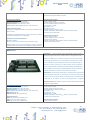
1
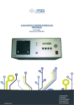
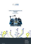
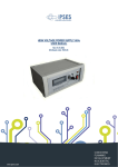
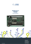
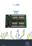
CAN I/O Control Unit USER MANUAL Rel. 01.00.0004 (Hardware code: CAN I/O) 1 www.ipses.com CAN I/O Control Unit USER MANUAL _____________________________ Information provided in this manual is property of IPSES S.r.l. and must be considered and treated as confidential. This publication can only be reproduced, transmitted, transcribed or translated into any human or computer language with the written consent of IPSES S.r.l. Information in this documentation has been carefully checked and is believed to be accurate as of the date of publication; however, no responsibility is assumed of inaccuracies. IPSES will not be liable for any consequential or incidental damages arising from reliance on the accuracy of this documentation. Information contained in this manual is subject to change without notice and does not represent a commitment on the part of IPSES. The design of this instrument is subject to continue development and improvement. Consequently, the equipment associated to this document may incorporate minor changes in detail from the information hereafter provided. All brand or product names are trademarks or registered trademarks of their respective holders. This manual in English is the original version. Printed in Italy Copyright 2009-2015IPSES S.r.l. All rights reserved. 2 IPSES S.r.l. Via Suor Lazzarotto, 10 - 20020 Cesate (MI) - ITALY Tel. (+39) 02 39449519 Fax (+39) 02 700403170 http://www.ipses.com e-mail [email protected] CAN I/O Control Unit USER MANUAL GUARANTEE IPSES warrants to the end-user in accordance with the following provisions that its branded hardware products, purchased by the end-user from IPSES company or an authorized IPSES distributor will be free from defects in materials, workmanship and design affecting normal use, for a period of one year as of the original purchase date. Products for which proper claims are made will, at IPSES’s option, be repaired or replaced at IPSES’s expense1. Exclusions This Guarantee does not apply to defects resulting from: improper or inadequate installation, use or maintenance; actions or modifications by unauthorized third parties or the end-user; accidental or wilful damage or normal wear and tear. Making a claim Claims must be made by contacting IPSES office within the guarantee period. Please, contact: IPSES S.r.l. - Via Suor Lazzarotto, 10 - 20020 Cesate (MI) Italy Tel. (+39) 02 39449519 – (+39) 02 320629547 Fax (+39) 02 700403170 http://www.ipses.com - e-mail: [email protected] Limitation and Statutory Rights IPSES makes no other warranty, guarantee or like statement other than as explicitly stated above and this Guarantee is given in place of all other guarantees whatsoever, to the fullest extent permitted by law. In the absence of applicable legislation, this Guarantee will be the end-user’s sole and exclusive remedy against IPSES. General Provisions IPSES makes no express warranties or conditions beyond those stated in this warranty statement. IPSES disclaims all other warranties and conditions, express or implied, including without limitation implied warranties and conditions of merchantability and fitness for a particular purpose. IPSES’s responsibility for malfunctions and defects in hardware is limited to repair and replacement as set forth in this warranty statement. IPSES does not accept liability beyond the remedies set forth in this warranty statement or liability for incidental or consequential damages, including without limitation any liability for products not being available for use or for lost data or software. 1 With the exclusion of shipping costs for and from IPSES’s development office. 3 IPSES S.r.l. Via Suor Lazzarotto, 10 - 20020 Cesate (MI) - ITALY Tel. (+39) 02 39449519 Fax (+39) 02 700403170 http://www.ipses.com e-mail [email protected] CAN I/O Control Unit USER MANUAL WARNING! ELECTRICAL DEVICES COULD DAMAGE EQUIPMENT OR PROPERTY OR CAUSE PERSONAL INJURY This guide contains instructions and technical features of the CAN I/O Control Unit. Read with attention before attempting to install. It is the responsibility of the technician to undertake all the safety rules provided by the law during the installation and the use of this device. For any information which is not contained in this guide, please contact: IPSES S.r.l. - Via Suor Lazzarotto, 10 - 20020 Cesate (MI) Italy Tel. (+39) 02 39449519 – (+39) 02 320629547 Fax (+39) 02 700403170 http://www.ipses.com - e-mail: [email protected] 4 IPSES S.r.l. Via Suor Lazzarotto, 10 - 20020 Cesate (MI) - ITALY Tel. (+39) 02 39449519 Fax (+39) 02 700403170 http://www.ipses.com e-mail [email protected] CAN I/O Control Unit USER MANUAL TABLE OF CONTENTS REVISION HISTORY .......................................................................................................................................................... 6 GENERAL FEATURES ....................................................................................................................................................... 7 CARD DESCRIPTION ........................................................................................................................................................ 8 STATUS LEDS.................................................................................................................................................................. 13 DRIVER INSTALLATION .................................................................................................................................................. 13 SOFTWARE ...................................................................................................................................................................... 16 COMMUNICATION PROTOCOL ...................................................................................................................................... 22 FTD2XX.dll USAGE EXAMPLE ........................................................................................................................................ 24 FIRMWARE UPGRADE FUNCTIONALITY ...................................................................................................................... 25 PRODUCT CODE ............................................................................................................................................................. 26 TECHNICAL FEATURES .................................................................................................................................................. 26 OTHER AVAILABLE I/O CARDS ...................................................................................................................................... 27 CONTACTS ...................................................................................................................................................................... 32 SUPPORT INFORMATION ............................................................................................................................................... 33 PROBLEM REPORT......................................................................................................................................................... 33 ENGINEERING PROBLEM REPORT............................................................................................................................... 34 5 IPSES S.r.l. Via Suor Lazzarotto, 10 - 20020 Cesate (MI) - ITALY Tel. (+39) 02 39449519 Fax (+39) 02 700403170 http://www.ipses.com e-mail [email protected] CAN I/O Control Unit USER MANUAL REVISION HISTORY Manual revision history Revision/ Date 01.00.0000 January 2009 01.00.0001 January 2011 01.00.0002 April 2011 01.00.0003 April 2014 01.00.0004 June 2015 Change description Author First version Released Zancanato A. Modified driver installation chapter and added new Zancanato A. available I/O cards Added chapter with description of communication Zancanato A. protocol Minor changes Mancuso C. Update document layout Bottaccioli M. 6 IPSES S.r.l. Via Suor Lazzarotto, 10 - 20020 Cesate (MI) - ITALY Tel. (+39) 02 39449519 Fax (+39) 02 700403170 http://www.ipses.com e-mail [email protected] CAN I/O Control Unit USER MANUAL GENERAL FEATURES CAN I/O is a control unit, integrated on European Card Format (160 x 100 mm – 6,30 x 3,94 inches) equipped with CAN, USB and RS232 interfaces. The card can work as stand alone device on CAN BUS. Its configuration is achieved either through USB (in this case the board is self powered) or through RS232 interface. CAN I/O can manage sixteen optocoupled inputs and sixteen optocoupled outputs which are reciprocally isolated in two groups of eight. A driver to for USB is provided with the card. Besides, a configuration software is also provided with: this software allows to control the board either through USB and RS232 and allows to configure CAN working parameters (such as baudrate, high and low speed, etc...). 7 IPSES S.r.l. Via Suor Lazzarotto, 10 - 20020 Cesate (MI) - ITALY Tel. (+39) 02 39449519 Fax (+39) 02 700403170 http://www.ipses.com e-mail [email protected] CAN I/O Control Unit USER MANUAL CARD DESCRIPTION CAN I/O card is shown in the pictures below. In the upper part of the card there are the sixteen outputs which are numbered from 0 up to 7 on the card serigraphy, divided in two groups. In the lower part of the card there are the sixteen inputs, numbered and divided as the outputs. CAN, USB, RS232, external supply connectors and configuration jumpers are also shown ATTENTION: IN ORDER TO PRECLUDE MALFUNCTIONING OR DAMAGE DO NOT CONNECT EXTERNAL POWER SUPPLY AND USB AT THE SAME TIME CAN J5 RS232 J1, J2, J3, J4 USB External Supply Picture 1a: CAN I/O card, jumper and interfaces 8 IPSES S.r.l. Via Suor Lazzarotto, 10 - 20020 Cesate (MI) - ITALY Tel. (+39) 02 39449519 Fax (+39) 02 700403170 http://www.ipses.com e-mail [email protected] CAN I/O Control Unit USER MANUAL STATUS LED OUT1 ÷ OUT8 OUT9 ÷ OUT16 L1, L2, L3, L4 L5, L7, L8 LED 9 to LED 24 LED 25 to LED 40 LINK LED IN1 ÷ IN8 IN9 ÷ IN16 Picture 1b: CAN I/O card, jumper and interfaces The Jumpers are (Picture 1a): J1 J2 J3 J4 J5 If inserted before start up, it sets the device in firmware update mode If inserted, it sets the RS232 communication Reserved Reserved If inserted, it enables the CAN BUS terminate resistor (between CAN-H and CAN-L) The LEDs are (Picture 1b): LINK Green LED: USB has been recognized and can communicate 9 IPSES S.r.l. Via Suor Lazzarotto, 10 - 20020 Cesate (MI) - ITALY Tel. (+39) 02 39449519 Fax (+39) 02 700403170 http://www.ipses.com e-mail [email protected] CAN I/O Control Unit USER MANUAL STATUS L1 L2 L3 L4 L5 L7 L8 L9 L10 L11 L12 L13 D14 L15 L16 L17 L18 L19 L20 L21 L22 L23 L24 L25 L26 L27 L28 L29 L30 L31 L32 L33 L34 L35 L36 L37 L38 L39 L40 Green LED: CAN enabled Red LED: RS232 enabled (if it is off ,USB is enabled) Red LED: reserved Red LED: reserved Red LED: reserved Red LED: reserved Red LED: firmware update mode Red LED: check transceiver CAN Red LED: OUT 1 enabled Red LED: OUT 2 enabled Red LED: OUT 3 enabled Red LED: OUT 4 enabled Red LED: OUT 5 enabled Red LED: OUT 6 enabled Red LED: OUT 7 enabled Red LED: OUT 8 enabled Red LED: OUT 9 enabled Red LED: OUT 10 enabled Red LED: OUT 11 enabled Red LED: OUT 12 enabled Red LED: OUT 13 enabled Red LED: OUT 14 enabled Red LED: OUT 15 enabled Red LED: OUT 16 enabled Green LED: Vhigh applied at IN 1 Green LED: Vhigh applied at IN 2 Green LED: Vhigh applied at IN 3 Green LED: Vhigh applied at IN 4 Green LED: Vhigh applied at IN 5 Green LED: Vhigh applied at IN 6 Green LED: Vhigh applied at IN 7 Green LED: Vhigh applied at IN 8 Green LED: Vhigh applied at IN 9 Green LED: Vhigh applied at IN 10 Green LED: Vhigh applied at IN 11 Green LED: Vhigh applied at IN 12 Green LED: Vhigh applied at IN 13 Green LED: Vhigh applied at IN 14 Green LED: Vhigh applied at IN 15 Green LED: Vhigh applied at IN 16 10 IPSES S.r.l. Via Suor Lazzarotto, 10 - 20020 Cesate (MI) - ITALY Tel. (+39) 02 39449519 Fax (+39) 02 700403170 http://www.ipses.com e-mail [email protected] CAN I/O Control Unit USER MANUAL OUTPUT The sixteen outputs are completely isolated both between them in two groups of eight and with other signals on the device. Here below there are the diagrams of two typical connections of external device to CAN I/O card: in the first case, the card will manage directly some loads (with maximal current of 150mA). In the second case, the card is connected to a high impedance device (i. e. the inputs of a PLC). Picture 2a: diagram of the output connections. Picture 2b: diagram of the output connections. Output status is displayed by LED placed near every connector (LED from L9 to L24). 11 IPSES S.r.l. Via Suor Lazzarotto, 10 - 20020 Cesate (MI) - ITALY Tel. (+39) 02 39449519 Fax (+39) 02 700403170 http://www.ipses.com e-mail [email protected] CAN I/O Control Unit USER MANUAL INPUT The sixteen inputs are completely isolated both between them in two groups of eight and toward other signals on the device. We suggest to connect inputs following one of the two diagrams displayed below: -picture 3a: in case inputs have to detect the pression of a switch or an open collector output. -picture 3b: in case inputs are directly controlled by a voltage. Picture 3a: diagram of input implementation. Picture 3b: diagram of input implementation. Input status is displayed by LEDs placed near every connector (LED form L25 to L40). 12 IPSES S.r.l. Via Suor Lazzarotto, 10 - 20020 Cesate (MI) - ITALY Tel. (+39) 02 39449519 Fax (+39) 02 700403170 http://www.ipses.com e-mail [email protected] CAN I/O Control Unit USER MANUAL STATUS LEDS LED STATUS OFF ON Status description CAN in SLEEP mode CAN enabled LED L8 OFF BLINKING ON Status description Device ready for the use transceiver CAN check-up transceiver CAN lacking or damaged DRIVER INSTALLATION We recommend to execute the automatic software installation from CD before connect the device to PC. By this way software and USB driver for CAN I/O are installed, allowing the PC to automatically identify the device once you connect it. If you use the recommend automatic software installation from CD , do not follow all the others indications contained in this chapter. If you DO NOT install the software CAN Manager and you use the card CAN I/O you need to install only the USB IPSES driver that is certified for the most recent Microsoft operating systems: - Microsoft Windows 2000 family - Microsoft Windows XP family, x86 - Microsoft Windows Server 2003 family, x86 - Microsoft Windows Server 2003 family, x64 - Microsoft Windows XP family, x64 - Microsoft Windows Vista family, x86 - Microsoft Windows Vista family, x64 - Windows Server 2008 family, x86 - Windows Server 2008 family, x64 –Windows 7 - Windows 7 x64 - Windows Server 2008 Release 2 family, x64 If your PC has an internet connection, you should follow the automatic Windows Update procedure, otherwise follow the manual installation procedure from CD. 13 IPSES S.r.l. Via Suor Lazzarotto, 10 - 20020 Cesate (MI) - ITALY Tel. (+39) 02 39449519 Fax (+39) 02 700403170 http://www.ipses.com e-mail [email protected] CAN I/O Control Unit USER MANUAL Automatic Windows Update procedure 1) Connect the CAN I/O to PC using a USB cable. Windows operating system will detect a new device, showing a message similar to: 2) In the following windows “found new hardware wizard” chose “Yes, this time only” and then “Next”. 3) Then choose “install the software automatically (Recommended)” and then “Next”. Wait for downloading of the driver and its installation. 14 IPSES S.r.l. Via Suor Lazzarotto, 10 - 20020 Cesate (MI) - ITALY Tel. (+39) 02 39449519 Fax (+39) 02 700403170 http://www.ipses.com e-mail [email protected] CAN I/O Control Unit USER MANUAL 4) Installation is displayed. Choose completed when the window on the left is “Finish” to exit. 5) After a window with the message “Found New Hardware. USB Serial Port” is displayed. Follow again instruction from point 2) Manual driver installation procedure 1) Connect the CAN I/O to PC using a USB cable. Windows operating system will detect a new device, showing a message similar to: 2) In the following windows “found new hardware wizard” chose “No, not this time” and then “Next”. 3) Then choose “install from a list or specific location (Advanced)” and “Next”. Then Set the driver folder path on the CD provided with. 15 IPSES S.r.l. Via Suor Lazzarotto, 10 - 20020 Cesate (MI) - ITALY Tel. (+39) 02 39449519 Fax (+39) 02 700403170 http://www.ipses.com e-mail [email protected] CAN I/O Control Unit USER MANUAL 4) The Successful of the installation is indicated by the message of completing the found new hardware wizard. To click "Finish". end, 5) After installation of the hardware described above, the new device "USB Serial Port" is detected. Follow again instruction from point 2). SOFTWARE A CD with a demo software is provided with the card. This software allows to manage CAN I/O main functions. Main window description In the picture below there is a snapshot of the software main window. 16 IPSES S.r.l. Via Suor Lazzarotto, 10 - 20020 Cesate (MI) - ITALY Tel. (+39) 02 39449519 Fax (+39) 02 700403170 http://www.ipses.com e-mail [email protected] CAN I/O Control Unit USER MANUAL Picture 4: Main windows of the software. The main windows is divided in four zone which, in the picture above, are surrounded respectively in blue, yellow, green and red. The blue surrounded zone includes commands to enable or to disable CAN interface using the available button. When CAN interface is enabled, the CAN Status LED turns green and CAN settings are shown If CAN interface is enabled, the device executes a BUS scan. CAN messages appear in the yellow surrounded zone. The number of messages shown in the text box can be changed using the indicator number which is in the lower part of the window. The CAN log can be saved as ASCII file choosing Save CAN log from CAN Option menu. The device can send messages in the following modes all customizable by the user: standard or extended, single or periodic. The green surrounded zone allows the user to insert: CAN address, message length and data to be sent. To send a single message, set the period at zero; in case of periodic messages, set the period value. We suggest to disable the show sent message function from CAN Option menu if you send periodic messages, because in this case the software becomes slow. The device is also equipped with a temperature sensor. Push the button in the red surrounded zone to read the board measured temperature. Config Panel description Before using CAN interface, the device must be configured. The configuration is made through the Config panel (Picture 5). To enable it, select Config CAN from CAN Option menu. 17 IPSES S.r.l. Via Suor Lazzarotto, 10 - 20020 Cesate (MI) - ITALY Tel. (+39) 02 39449519 Fax (+39) 02 700403170 http://www.ipses.com e-mail [email protected] CAN I/O Control Unit USER MANUAL Picture 5: Config Panel. Configuration panel allows to set: speed (the user can change manually the registers or he can choose a pre-calculate speed), mask, filters and activation of CAN Commands. Description of Command Configuration Window The CAN Command Windows allows to set card address and CAN Commands. The CAN Commands are: read input, write output, read temperature. Thanks to these commands it is possible to communicate through CAN. To configure CAN commands, it is necessary to assign an address to CAN I/O and to configure command data (the first bytes of CAN messages). Default configuration is 500 kbps speed with no filters. The Command Configuration Window (Picture 6) can be opened from Command menu choosing Config CAN Command. Picture 6: Command Configuration Window Default configuration is 500 Kbps speed with the following parameters: 18 IPSES S.r.l. Via Suor Lazzarotto, 10 - 20020 Cesate (MI) - ITALY Tel. (+39) 02 39449519 Fax (+39) 02 700403170 http://www.ipses.com e-mail [email protected] CAN I/O Control Unit USER MANUAL ADDRESS: . . . . . . . . . . . . . . . . . . . . .64A (hex) READ TEMPERATURE COMMAND: . . . . . . 3A (hex) READ INPUT COMMAND: . . . . . . . . . . . . 3B (hex) WRITE OUTPUT COMMAND: . . . . . . . . . . 3C (hex) CAN Command Description CAN message to write CAN I/O Output must contain: 1 - CAN I/O address (defined by users) 2 – the first byte which is the write output command (defined by users) 3 – the second byte which is the output state (from 1 up to 8) 4 – the third byte which is the output state (from 9 up to 16) OTHER BYTES WILL BE IGNORED Example (ref. Picture 6): CAN message to enable the fourth and the eleventh output are: Direction IN OUT Address 5D8(hex) 5D8(hex) Byte 1 1(hex) 41(hex) Byte 2 8(hex) 8(hex) Byte 3 4(hex) 4(hex) Other Byte IGNORE Not present CAN message to get CAN I/O input state must contain: 1 - CAN I/O address (defined by users) 2 – The first byte which is the read input command (defined by users) OTHER BYTES WILL BE IGNORED Example (ref. Picture 6): CAN message to read the CAN I/O input state. The reply shows the fourth and eleventh inputs are high. Direction IN OUT Address 5D8(hex) 5D8(hex) Byte 1 2(hex) 42(hex) Byte 2 IGNORE 8(hex) Byte 3 IGNORE 4(hex) Other Byte IGNORE Not present CAN message to get board measured temperature must contain: 1 - CAN I/O address (defined by users) 2 – The first byte which is the read temperature command (defined by users) OTHER BYTES WILL BE IGNORED Example (ref. Picture 6): CAN message to read temperature: the reply shows a temperature of 21.19°C calculate as follows: 153(hex)*0.0625(dec)°C=21.1875°C Direction IN Address 5D8(hex) Byte 1 3(hex) Byte 2 IGNORE Byte 3 IGNORE Other Byte IGNORE 19 IPSES S.r.l. Via Suor Lazzarotto, 10 - 20020 Cesate (MI) - ITALY Tel. (+39) 02 39449519 Fax (+39) 02 700403170 http://www.ipses.com e-mail [email protected] CAN I/O Control Unit USER MANUAL OUT 5D8(hex) 43(hex) 1(hex) 53(hex) Not present Check inputs and outputs using software Through software it is possible to read input status or to write the output status using the relevant window (Picture 7) which can be opened choosing Read Input Logic or Write Output Logic from Command menu. Picture 7: Logic Input/Output Windows. Trhough Logic Output Status windows it is possible to configure CAN I/O output start up status. To do this, write the values and then push Make these Start Up values button, the start up output values are shown under the check box. Stand Alone Mode CAN I/O can work on a CAN BUS with no PC and software. To enable the stand alone mode it is enough to connect CAN interface and power supply the card either from USB or from an external power supply. (ATTENTION: IN ORDER TO PRECLUDE MALFUNCTIONING OR DAMAGE DO NOT CONNECT EXTERNAL POWER SUPPLY AND USB AT THE SAME TIME). Default configuration is 500 Kbps speed with the following parameters: ADDRESS: . . . . . . . . . . . . . . . . . . . . .64A (hex) READ TEMPERATURE COMMAND: . . . . . . 3A (hex) READ INPUT COMMAND: . . . . . . . . . . . . 3B (hex) WRITE OUTPUT COMMAND: . . . . . . . . . . 3C (hex) CAN default configuration can be modified and saved when you exit form the software. The device reloads the parameters automatically at the start up. 20 IPSES S.r.l. Via Suor Lazzarotto, 10 - 20020 Cesate (MI) - ITALY Tel. (+39) 02 39449519 Fax (+39) 02 700403170 http://www.ipses.com e-mail [email protected] CAN I/O Control Unit USER MANUAL Statistic Window Description The software can find the period of different CAN messages on the BUS. This feature is available in CAN Option menu when CAN interface is enabled. Picture 7: Statistic Window. The user can customize the watching time window, the refresh period and he can filter one or more bytes from the CAN message. 21 IPSES S.r.l. Via Suor Lazzarotto, 10 - 20020 Cesate (MI) - ITALY Tel. (+39) 02 39449519 Fax (+39) 02 700403170 http://www.ipses.com e-mail [email protected] CAN I/O Control Unit USER MANUAL COMMUNICATION PROTOCOL Is possible to use some features of the board through a direct communication with RS232 or USB interfaces. If you want use the USB interface you need to install the driver supply with the board and include the dynamic library FTD2XX.dll. Otherwise, if you use the RS232 interface, no drivers installation is required. ATTENTION: IN ORDER TO PRECLUDE MALFUNCTIONING OR DAMAGE DO NOT CONNECT EXTERNAL POWER SUPPLY AND USB AT THE SAME TIME Every command sent to the board must be formatted in the following way: <FRMDELM> <CMD> <Data> <FRMDELM> Where <FRMDELM> is the byte that delimit the command frame “0x20”, <CMD> is the byte that identify the command and <Data> are the command parameters. The board response format is: <CMD> <Data> Where <CMD> is the command executed and <Data> are the requested parameters. The available commands are: The output write command (<CMD>=0x51) followed by two byte which bits represent the 16 outputs status. The board respond only <CMD> byte Example: command: 0x20 0x51 0x81 0x18 0x20 reply: 0x51 effect: the outputs 0, 7 of the first block and the outputs 3, 4 of the second block are now active. The command that set the current output status as start-up status (<CMD>=0x48). The board respond only <CMD> byte Example: command: 0x20 048 0x20 reply: 0x48 status: The current output status is set as Start-Up status The read input command (<CMD>=0x52). The board respond with <CMD> byte followed by two byte which bits represent the 16 inputs status. Example: command: 0x20 0x52 0x20 reply: 0x52 0x81 0x18 status: the inputs 0, 7 of the first block and the inputs 3, 4 of the second block are active The read temperature command (<CMD>=0x50. The board respond with <CMD> byte followed by two byte that represent a 16 bit integer number. You can find the temperature multiply this number for 0.0625. Example: command: 0x20 0x50 0x20 reply: 0x50 0x01 0x93 interpretation: The 16 bit number is -> 0x0193=403 the temperature is 403*0.0625=25.19°C 22 IPSES S.r.l. Via Suor Lazzarotto, 10 - 20020 Cesate (MI) - ITALY Tel. (+39) 02 39449519 Fax (+39) 02 700403170 http://www.ipses.com e-mail [email protected] CAN I/O Control Unit USER MANUAL 23 IPSES S.r.l. Via Suor Lazzarotto, 10 - 20020 Cesate (MI) - ITALY Tel. (+39) 02 39449519 Fax (+39) 02 700403170 http://www.ipses.com e-mail [email protected] CAN I/O Control Unit USER MANUAL FTD2XX.dll USAGE EXAMPLE This example show the usage of the USB dynamic library FTD2XX.dll for a direct board communication. The example was write in C but you can use this library with any program language. /************************************************************************/ // Open Device Communication /************************************************************************/ if ((*FT_Open_Ptr) (0, &Handle_device)) { MessagePopup ("ERROR",OPEN_ERROR_MSG ); goto Error; } /************************************************************************/ // Read temperature /************************************************************************/ //send command buffer=malloc(3); buffer[0]=FRAME; buffer[1]=CMD_READ_TEMPERATURE; buffer[2]=FRAME; if ((*FT_Write_Ptr) (Handle_device, buffer, 3, &ByteWrite)) { MessagePopup ("ERROR",WRITE_ERROR_MSG ); free(buffer); goto Error; } //read answer if ((*FT_Read_Ptr) (Handle_device, buffer, 3, &ByteRead)) { MessagePopup ("ERROR",READ_ERROR_MSG ); free(buffer); goto Error; } if (*buffer!=CMD_READ_TEMPERATURE) { MessagePopup ("ERROR",READ_ERROR_MSG ); free(buffer); goto Error; } temperature = ((buffer[1]<<8)+buffer[2])*0.0625; free(buffer); buffer=malloc(50); sprintf (buffer, "Temperature: %f", temperature); MessagePopup ("ERROR", buffer); free(buffer); 24 IPSES S.r.l. Via Suor Lazzarotto, 10 - 20020 Cesate (MI) - ITALY Tel. (+39) 02 39449519 Fax (+39) 02 700403170 http://www.ipses.com e-mail [email protected] CAN I/O Control Unit USER MANUAL FIRMWARE UPGRADE FUNCTIONALITY CAN I/O is provided with a Boot Loading for firmware update by USB. To set the unit in firmware upgrade mode, select jumper J1 before switching on the device. To do firmware Upgrade a specific software shown in figure 9 must be used. Firmware upgrading is not possible through RS232 or CAN. Picture 8: Firmware upgrade software start-up. Open the new firmware file pushing Open File button, then activate connection choosing Connect Device button (if the connection is disabled the LED stays off), then push Download Firmware and wait for the pop-up message (fail or pass). Picture 10: file loaded. 25 IPSES S.r.l. Via Suor Lazzarotto, 10 - 20020 Cesate (MI) - ITALY Tel. (+39) 02 39449519 Fax (+39) 02 700403170 http://www.ipses.com e-mail [email protected] CAN I/O Control Unit USER MANUAL PRODUCT CODE Code Description CAN I/O CAN I/O-DIN USB-A-B USB-A-B-ill CAN I/O control card CAN I/O control card mounted on a universal support for DIN rail USB cable to connect USB cards USB cable with light end to connect USB cards TECHNICAL FEATURES Power supply: USB configuration mode: self powered through USB Stand alone mode: 5V external supply or self powered through USB RS232 configuration mode: 5V external supply Working temperature: from 0°C up to +60°C Storage temperature: from -40°C up to +85°C Interface toward: 1 USB port type B, compatible with USB2.0 and RS232 Card dimensions: 160 x 100 mm (6.30 x 3.94 inches) Inputs: sixteen optocoupled inputs, reciprocally isolated in two groups of eight, which can support a max voltage of 36V low level: lower then 1V high level: higher then 2,5V impedance: about 2,5 kΩ Outputs: sixteen optocoupled outputs, reciprocally isolated in two groups of eight, which can support a max voltage of 36V and max current of 150mA. CAN: configurable High-speed o Low-speed with customize band rate (up to 1MB/s) and support for extended or standard frame. Protection: optocouplers with operative isolation voltage of 2.500 max RMS Thermal sensor: Resolution: 0,0625°C Accuracy: ±1°C (max) from 25°C to 65°C ±2°C (max) from -40°C to 25°C and from 65°C to 85°C ±3°C (max) from -55°C to -40°C and from 85°C to 125°C 26 IPSES S.r.l. Via Suor Lazzarotto, 10 - 20020 Cesate (MI) - ITALY Tel. (+39) 02 39449519 Fax (+39) 02 700403170 http://www.ipses.com e-mail [email protected] CAN I/O Control Unit USER MANUAL OTHER AVAILABLE I/O CARDS IO‐69: Input/output Card with 6 inputs and 9 relay outputs and USB interface IO‐69‐USB is a self‐powered card to manage six optocoupled inputs and nine relay outputs with USB interface. A timeout control allows to protect the connecting devices, turning off all the outputs if it does not receive commands from the host within a time configurable through software. Furthermore, there is the possibility to program all the outputs so that each one will activate only when inputs reach assigned conditions: in this case, IO‐ 69 acts like a programmable logic controller (PLC). The card is produced in two versions: with single pole double throw relay (SPDT) and with single pole single throw relay (SPST). General technical features: Power supply: selfpowered thorugh USB Working temperature: from 0°C up to + 60°C Storage temperature: from ‐40°C up to + 85°C Size: European format card (100 x 160 mm ‐ 3,94 x 6,30 inches) USB port technical features: 1 type B port, compatible with USB 2.0, autonomously powered for the host connection Possibility to connect directly to an host port up to 256 cards for a maximum of 1.536 inputs and 2.304 outputs. Technical features of inputs: Number of inputs: six Operative Voltage: independently selectable for each input at 5V/12V/24V (DC) Protection: optocouplers with 2.500VRMS maximum operative voltage Connectors: pitch terminal block Technical features of outputs: Number of outputs: nine SPDT version: ‐ Type: relay single pole double throw ‐ Max switching current: 0,25A ‐ Max carrying current: 0,5A ‐ Max switching voltage: 70VAC/100VDC, potential free ‐ Max contact resistance: 200mΩ SPST version: ‐ Type: relay single pole single throw ‐ Max switching current: 0,5A ‐ Max carrying current: 1A ‐ Max switching voltage: 100VAC/DC, potential free ‐ Max contact resistance: 150mΩ Isolation voltage between coil and contacts: 500VDC. Connectors: pitch terminal block Timeout control to turn off all the outputs if it does not receive commands from the host within a time configurable through software. IO‐1616: Input/output Card with 16 inputs and 16 outputs and USB interface IO1616 is a self powered card to manage sixteen optoisolated inputs and sixteen optoisolated outputs with USB interface. IO1616 can be directly connected to PLC, to input devices from operator and to other I/O systems. 27 IPSES S.r.l. Via Suor Lazzarotto, 10 - 20020 Cesate (MI) - ITALY Tel. (+39) 02 39449519 Fax (+39) 02 700403170 http://www.ipses.com e-mail [email protected] CAN I/O Control Unit USER MANUAL On request, an integrated temperature sensor allows to know in real time the temperature of the system IO1616 is placed in. General technical features: Power supply: self‐powered thorugh USB Working temperature: from 0°C up to + 60°C Storage temperature: from ‐40°C up to + 85°C Size: European format card (100 x 160 mm ‐ 3,94 x 6,30 inches) USB port technical features: 1 type B port, compatible with USB 2.0, autonomously powered for the host connection ‐ Possibility to connect directly to an host port up to 128 cards, cards for a maximum of 2.048 inputs and 2.048 outputs Temperature sensor technical features: Resolution: 0,0625°C Accuracy: from ±1°C to ±3°C, depending on temperature range. Timeout control to turn off all the outputs if it does not receive commands from the host within a time configurable through software. Technical features of inputs: Number of inputs: sixteen Operative voltage: from 3,3VDC up to 36VDC Max current absorbed: 10mA (on each input) Input impedance: ≈ 2.5KΩ Logic low level: < 1V Logic high level: > 2.5V Port read average time execution: 15 ms Protection: optocouplers with 2.500VRMS maximum operative voltage Connectors: pitch terminal block Technical features of outputs: Number of outputs: sixteen Operative voltage: from 3,3VDC up to 36VDC Maximum current: 150 mA Protection: optocouplers with 2.500VRMS maximum operative voltage Connectors: pitch terminal block WEB‐IO‐WiFi: Input/output Card with 16 inputs and 16 outputs, Ethernet and WiFi interfaces, integrated web, telnet and SNMP servers WEB‐IO‐WiFi is a card to manage sixteen optocoupled inputs and sixteen optocoupled outputs with Ethernet and WiFi interfaces, equipped with a web, a telnet and an SNMP servers. The web server allows to connect and to manage the card using any web browser (i. e. Internet Explorer or Firefox), with no needs to install a software on your PC. Beside, the card can be connected directly to a switch or to a router, by this way it can be accessed by any PC connected to Internet. It is also possible to develop a customized software managed by telnet service or SNMP client. The board is available with built‐in antenna or with ultra miniature coaxial (U.FL) connector for external antenna connection. WEB‐IO‐WiFi can be directly connected to PLC, to input devices from operator and to other I/O systems. Each input and output status can be read by a web browser or a telnet client at any moment, besides it is shown directly on the board thanks to LEDs fixed on. On request, the card can be equipped with an integrated temperature sensor which allows to monitor in real time the temperature around the regulator voltage module. General technical features: Power supply: external, from 5VDC to 32VDC Working temperature: from 0°C u to + 60°C Storage temperature: from ‐40°C up to + 85°C Size: European format card (100 x 160 mm ‐ 3,94 x 6,30 inches) Max thickness: 20 mm Ethernet interface: 1 Ethernet RJ45 port Supported protocols: Telnet: the card can work as telnet server HTTP: the card can work as web server SNMP: the card can work as SNMP server Technical features of inputs: Number of inputs: sixteen Operative voltage: from 3,3VDC to 36VDC Max absorbed current: 10mA (on each input) Logic low level: < 1V Logic high level: > 2.5V Input impedance: ≈ 2.5KΩ Protection: optocouplers with 2.500VRMS maximum operative voltage Connectors: pitch terminal block Technical features of outputs: Number of outputs: sixteen 28 IPSES S.r.l. Via Suor Lazzarotto, 10 - 20020 Cesate (MI) - ITALY Tel. (+39) 02 39449519 Fax (+39) 02 700403170 http://www.ipses.com e-mail [email protected] CAN I/O Control Unit USER MANUAL WiFi technical features: ‐ Compatibility: WiFi 802.11b (2,4GHz). ‐ Security: WEP, WPA and WPA2. ‐ Transmit power: 10dBm (10mW). ‐ Receiver sensitivity: ‐83dBm ‐Built‐in antenna or ultra miniature coaxial (U.FL) connector for external antenna connection ‐ Configurable to connect to any Access Point, with any channel and SSID. Operative voltage: from 3,3VDC to 36VDC Max open collector current: 150mA Protection: optocouplers with 2.500VRMS maximum operative voltage Connectors: pitch terminal block Temperature sensor technical features: Resolution: 0,0625°C Accuracy: from ±1°C to ±3°C, depending on temperature range. Timeout control to turn off all the outputs if it does not receive commands from the host within a time configurable through software. WEB‐ADIO: Input/output Card with 8 analogical inputs, 8 digital inputs, 8 analogical outputs and 8 digital outputs, Ethernet interface, integrated web, telnet and SNMP servers WEB‐ADIO is a card to manage 8 optocoupled digital inputs, 8 analogical inputs, 8 optocoupled digital outputs and 8 analogical outputs with Ethernet interface, equipped with a web, a telnet and an SNMP servers. The WEB server allows to connect and to manage the card using any web browser (i. e. Internet Explorer and Firefox), with no needs to install a software on your PC Beside, the card can be connected directly to a switch or to a router with no need to use a PC. It is also possible to develop a customized software managed by telnet service. WEB‐ADIO can be directly connected to PLC or to analogical transducer, to input devices from operator and to other I/O systems. The analogical inputs and outputs have an operative voltage from 0V to 10V, with a resolution of 10mV and are calibrated one by one. Each input and output status can be read by a web browser or a telnet client at any moment, besides, the status of digital inputs and outputs it is shown directly on the board thanks to LEDs fixed on. On request, the card can be equipped with an integrated temperature sensor which allows to monitor in real time the temperature around the regulator voltage module. General technical features: Power supply: external, from 12VDC to 15VDC Working temperature: from 0°C up to + 60°C Storage temperature: from ‐40°C up to + 85°C Size: European format card (100 x 160 mm ‐ 3,94 x 6,30 inches) Max thickness: 20mm Ethernet interface: 1 Ethernet RJ45 port Supported protocols: Telnet: the card can work as telnet server HTTP: the card can work as web server SNMP: the card can work as SNMP server Temperature sensor technical features: Resolution: 0,0625°C Accuracy: from ±1°C to ±3°C, depending on temperature range. Timeout control to turn off all the digital outputs if it does not receive commands from the host within a time configurable through software. Technical features of inputs: Number of inputs: sixteen: 8 analogical and 8 digital Operative voltage of digital inputs: from 3,3VDC to 36VDC Operative voltage of analogical inputs: from 0V to 10V (10 bit ADC). Max current absorbed on each input: Digital: 10mA. Analogical: 1mA. Input impedance: Digital: ≈2,5kΩ. Analogical: ≈15kΩ. Logic low level: < 1V Logic high level: > 2.5V Protection: Digital: optocouplers with 2.500VRMS maximum operative voltage. Analogical: overvoltage protection through calmp diodes. Connectors: pitch terminal block Technical features of outputs: Number of outputs: sixteen: 8 analogical and 8 digital Operative voltage of digital outputs: from 3,3V to 36V (DC). Operative voltage of analogical outputs: from 0V to 10V (10 bit DAC). Max current (on each output): Digital: 150mA. Analogical: ± 25mA. Response average time: Digital: 100µs. Analogical: 6ms (from 10% to 90% of the whole dynamic). Protection of digital outputs: optocouplers with 2.500VRMS maximum operative voltage. Connectors: pitch terminal block 29 IPSES S.r.l. Via Suor Lazzarotto, 10 - 20020 Cesate (MI) - ITALY Tel. (+39) 02 39449519 Fax (+39) 02 700403170 http://www.ipses.com e-mail [email protected] CAN I/O Control Unit USER MANUAL WEB‐ADIO‐WiFi: Input/output Card with 8 analogical inputs, 8 digital inputs, 8 analogical outputs and 8 digital outputs, Ethernet and WiFi interfaces, integrated web, telnet and SNMP servers WEB‐ADIO‐WiFi is a card to manage 8 optocoupled digital inputs, 8 analogical inputs, 8 optocoupled digital outputs and 8 analogical outputs with Ethernet and WiFi interfaces, equipped with a web, a telnet and an SNMP servers. The web server allows to connect and to manage the card using any web browser (i. e. Internet Explorer and Firefox), with no needs to install a software on your PC Beside, the card can be connected directly to a switch or to a router with no need to use a PC. The board is available with built‐in antenna or with ultra miniature coaxial (U.FL) connector for external antenna connection. It is also possible to develop a customized software managed by telnet service. The analogical inputs and outputs have an operative voltage from 0V to 10V, with a resolution of 10mV and are calibrated one by one. WEB‐ADIO‐WiFi can be directly connected to PLC or to analogical transducer, to input devices from operator and to other I/O systems. Each input and output status can be read by a WEB browser or a telnet client at any moment, besides, the status of digital inputs and outputs it is shown directly on the board thanks to LEDs fixed on. General technical features: Power supply: external, from 15VDC to 32VDC Working temperature: from 0°C up to + 60°C Storage temperature: from ‐40°C up to + 85°C Size: European format card (100 x 160 mm ‐ 3,94 x 6,30 inches) Max thickness: 20mm Ethernet interface: 1 Ethernet RJ45 port Supported protocols: Telnet: the card can work as telnet server HTTP: the card can work as web server SNMP: the card can work as SNMP server WiFi technical features: ‐ Compatibility: WiFi 802.11b (2,4GHz). ‐ Security: WEP, WPA and WPA2. ‐ Transmit power: 10dBm (10mW). ‐ Receiver sensitivity: ‐83dBm ‐Built‐in antenna or ultra miniature coaxial (U.FL) connector for external antenna connection ‐ Configurable to connect to any Access Point, with any channel and SSID. Timeout control to turn off all the digital outputs if it does not receive commands from the host within a time configurable through software. Technical features of inputs: Number of inputs: sixteen: 8 analogical and 8 digital Operative voltage of digital inputs: from 3,3VDC to 36VDC . Operative voltage of analogical inputs: from 0V to 10V (10 bit ADC). Max current absorbed on each input: Digital: 10mA. Analogical: 0,1mA. Input impedance: Digital: ≈2,5kΩ. Analogical: >1MΩ. Logic low level: < 1V Logic high level: > 2.5V Protection: Digital: optocouplers with 2.500VRMS maximum operative voltage. Analogical: overvoltage protection through clamp diodes. Connectors: pitch terminal block Technical features of outputs: Number of outputs: sixteen: 8 analogical and 8 digital Operative voltage of digital outputs: from 3,3VDC to 36VDC . Operative voltage of analogical outputs: from 0V to 10V (10 bit DAC). Max current on each output: Digital: 150mA. Analogical: ± 25mA. Response average time: Digital: 100 µs. Analogical: 6ms (from 10% to 90% of the whole dynamic). Protections Digital: optocouplers with 2.500VRMS maximum operative voltage. Connectors: pitch terminal block 30 IPSES S.r.l. Via Suor Lazzarotto, 10 - 20020 Cesate (MI) - ITALY Tel. (+39) 02 39449519 Fax (+39) 02 700403170 http://www.ipses.com e-mail [email protected] CAN I/O Control Unit USER MANUAL IN8‐USB: Input Card with 8 inputs and USB interface IN8 is a low size auto powered control unit equipped with USB interface. IN8 can check eight galvanic isolated inputs: on each input it is possible to apply voltages regardless form the USB ground, with a maximum voltage of 30V. Easy to use, thanks to the driver provided with and to the LabVIEW 8.2 library available on demand, IN8 also reduce installation costs. The board low size to be easily integrated in several systems. Besides, IN8 has its inputs galvanically isolated to protect from electromagnetic disturbances and ground loops, improving its reliability and quality. IN8 is the right answer to the need to acquire digital signals from a PC in an industrial environment. General technical features: Power supply: self‐powered through USB Working temperature: from 0°C up to + 60°C Storage temperature: from ‐40°C up to + 85°C Size: 80 x 75 mm (2,95 x 3,15 inches) ‐ Possibility to connect directly to an host port up to 256 cards, for a maximum of 2.048 inputs USB port technical features: 1 type B port, compatible with USB 2.0, autonomously powered for the host connection Technical features of inputs: Number of inputs: 8 Operative voltage: from 3,3VDC up to 36VDC Max current absorbed: 10mA (on each input) Input impedance: ≈ 2.5KΩ Logic low level: < 1V Logic high level: > 2.5V Port read average time execution: 12 ms Protection: optocouplers with 2.500VRMS maximum operative voltage Connectors: pitch terminal block The state of the inputs is shown through LEDs on the board LabVIEW Library for I/O cards: A complete library for LabVIEW, giving the feasibility of I/O devices remote control, is available on request. The Library allows to implement a LabVIEW application without knowing the details of the communication protocol, making the development quick and easy. Each library is provided with a help file which explains deeper each function included with. 31 IPSES S.r.l. Via Suor Lazzarotto, 10 - 20020 Cesate (MI) - ITALY Tel. (+39) 02 39449519 Fax (+39) 02 700403170 http://www.ipses.com e-mail [email protected] CAN I/O Control Unit USER MANUAL CONTACTS IPSES S.r.l. conceives, projects and markets electronic and scientific instruments. The customized planning of our devices allows us to answer specific necessities for customers asking for embedded systems. IPSES clients enjoy access to a dedicated project engineering team, available as needed. Our pool consists of highly competent professionals whose experience in this field is extremely strong. Thanks to constant updating and technical development, IPSES is a leading company, combining the dynamism of a young group into the competence and reliability of a qualified staff. IPSES S.r.l. Research and development office: Via Suor Lazzarotto, 10 20020 Cesate (MI) Italy tel. (+39) 02 39449519 - (+39) 02 320629547 fax (+39) 02 700403170 e-mail: [email protected] http://www.ipses.com 32 IPSES S.r.l. Via Suor Lazzarotto, 10 - 20020 Cesate (MI) - ITALY Tel. (+39) 02 39449519 Fax (+39) 02 700403170 http://www.ipses.com e-mail [email protected] CAN I/O Control Unit USER MANUAL __________________________________ SUPPORT INFORMATION The customer is at liberty to contact the relevant engineer at IPSES S.r.l. directly. Telephone : Fax Email : : (+39) 02 39449519 (+39) 02 320629547 (+39) 02 700403170 [email protected] PROBLEM REPORT The next page is a standard template used for reporting system problems. It can be copied and send as a fax. Alternative bugs may be reported by emails, in this case please insure that the mail contains similar information listed in the Engineering Problem Report form. 33 IPSES S.r.l. Via Suor Lazzarotto, 10 - 20020 Cesate (MI) - ITALY Tel. (+39) 02 39449519 Fax (+39) 02 700403170 http://www.ipses.com e-mail [email protected] CAN I/O Control Unit USER MANUAL ENGINEERING PROBLEM REPORT Problem describer Name Company Date Tel. Fax IPSES s.r.l. Via Suor Lazzarotto, 10 Cesate (MI) Italy Fax (+39) 02 700403170 e-mail [email protected] Product Name Version Serial No. Report Type (bug, change request or technical problem) Major bug Minor bug Change request Technical problem Urgency: High Medium Low Problem Description Reproduction of Problem IPSES s.r.l. Action notes Received by Date Report No. Action 34 IPSES S.r.l. Via Suor Lazzarotto, 10 - 20020 Cesate (MI) - ITALY Tel. (+39) 02 39449519 Fax (+39) 02 700403170 http://www.ipses.com e-mail [email protected] CAN I/O Control Unit USER MANUAL (Product code CAN I/O Rel. 01.00.0004) IPSES S.r.l. Via Suor Lazzarotto, 10 20020 Cesate (MI) - ITALY Tel. (+39) 02 39449519 – (+39) 02 320629547 Fax (+39) 02 700403170 e-mail: [email protected] [email protected] 35 IPSES S.r.l. Via Suor Lazzarotto, 10 - 20020 Cesate (MI) - ITALY Tel. (+39) 02 39449519 Fax (+39) 02 700403170 http://www.ipses.com e-mail [email protected]