1
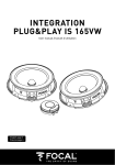
(044)361-05-06
ICQ:495-089-192
(067)469-02-12
ICQ:613-211-859
(099)048-99-03
(093)672-77-76
User's Manual
Car subwoofer Focal Utopia Be 13 WS
In the online store Winauto you also can buy car subwoofer Focal Utopia Be 13 WS . Delivery in Kiev and throughout
Ukraine with payment upon receipt!
http://winauto.ua
Car Receivers - Facia Plates - Head Units - TV and Monitors - Car Antennas - Car Audio - Car DVRs - GPS Navigation - Trip Computers - Security
Systems - Mechanical Locking - Car Park Systems - Cameras - Optic and Light - Car Tuning - Car Heating - Marine Audio and Electronics - Car
Accessories - Car Isolation - Car Installation Components - Car Batteries - Liquid and Oil -
Car audio and car goods internet store Winauto
Utopia Beryllium
the Spirit of Sound
a
u
.
o
t
u
a
in
w
Français page 31
Car audio and car goods internet store Winauto
a
u
.
o
t
u
a
in
w
2
Car audio and car goods internet store Winauto
Summary
Page
Precautions 4
Utopia Be line: User’s manual 5
Tweeters installation 7
Woofers / midranges mounting 9
a
u
.
o
t
u
N° 5 and N°6 Crossblock wiring 13
N°7 Crossblock wiring 15
Crossblock installation 17
N°5 and N°6 Crossblock settings 19
w
a
in
N°7 Crossblock settings 21
Utopia Be Active Kit 23
Subwoofers installation 25
Box enclosure mounting 27
Kits specifications 28
Subwoofers specifications 29
Conditions of guarantee 30
Dimensions 59
International guarantee 61
Notes 63
Serial numbers 64
3
English
Car audio and car goods internet store Winauto
Precautions
Special precautions regarding
the Beryllium dome tweeter
In its solid form, Beryllium is harmless. However, due to its nature,
certain special precautions should
be observed to avoid exposure to
unnecessary risk.
• Under no circumstances the
Beryllium dome should be subjected
to any form of abrasive action. To
ensure no accidental damage to the
tweeter dome it is advised to carefully
replace the protection cover.
• In the unlikely case of damage to
the dome, of any form, the supplied
piece of adhesive tape should be
immediately used to seal the whole
front surface of the tweeter. The
protective cover should then be
replaced and also taped securely
in place. You should then inform the
dealer from whom you purchased
the product so that the tweeter can
be removed by a professional and
returned to the product distributor
for replacement.
• If the dome is broken in any way
giving rise to loose particles of
Beryllium, they should be carefully
collected with the use of a supplied
adhesive tape and sealed in a ziptop bag to be returned with the
tweeter.
For further information, please contact
Focal-JMlab directly:
[email protected]
Warning
Continued listening at high volume
levels above 110dB, can damage
your hearing durably. Listening
above 130dB can damage your
hearing permently.
a
u
.
o
t
u
a
in
w
4
English
Running-in period
The drivers used in the Uopia
Be Line are made up of complex
mechanical elements and requires
an adaptation period before they
deliver their full potential. They must
get adapted to the temperature
and humidity conditions of their
environment. This running-in period
depends on the encountered conditions and can last several weeks.
In order to shorten this period,
we advise you to let your speaker
operate for about twenty hours at
medium level, playing standard
music programs, but with a large
amount of bass. Once the components of the speaker are completely stabilized, it is possible to
enjoy the real performances of your
speakers.
Car audio and car goods internet store Winauto
Utopia Be line: User’s manual
Congratulations on purchasing
a product from the Utopia Be
range. We are happy you share
our passion for “the Spirit of
Sound”. Designed using the latest
technologies, these speakers
continue Focals perfectionist
beliefs, developing products
with high power handling, and
unrivalled sound quality. To
obtain the best results from
this product, we recommend
that you follow carefully all the
information contained in this
user’s manual.
If not followed correctly any fault
observed, may not be covered by
the guarantee.
a
u
.
o
t
u
a
in
w
To confirm Focal-Jmlab’s guarantee, please register on line on our website: http://register.focal-fr.com,
or send the guarantee back to us within 10 days of purchase.
5
English
Car audio and car goods internet store Winauto
a
u
.
o
t
u
• Fig. 1
a
in
w
• Fig. 2 and 3
6
English
• Fig. 4 and 5
Car audio and car goods internet store Winauto
Tweeters installation
Location
TBe tweeter has been designed for
flush mounting (recommended)
or surface mounting installation,
using the two fixing kits provided.
Installation’s choice position is
extremely important. This is a major
factor for high frequency SPL, stability
of the acoustics, stereophonic
imaging, and overall staging. The
standard recommendation for an
ideal stereo imaging, is to ensure
the “left” and “right” tweeters are
installed in the same positions.
Also they are approximately at
equal distance to the driver (viceversa for the passenger). Various
positions advised should be checked
and comparatives made, for an
ideal positioning. Tweeter should
always be positioned ahead of the
normal listening position. The main
preferences are the outer positions
of the dashboard (fig. 1, A),
on the windscreeen pillars (fig. 1, B)
(only requires a small amount of
install work). The location close to
the door mirror (fig. 1, C) is also
regarded as a good position. Lastly
a position high in the door (fig. 1, D)
is also acceptable even if it is not
considered as the best to optimize
staging. It is imperative to check
before any installation is attempted,
that enough space is available
(especially
for
flush-mounting
appli-cations). Crossblock (included
in n°5, 6 and 7 kits) contains all
necessary functionalities to optimize
the tweeter setting, according to its
location and vehicle acoustic.
Surface mounting
Surface mounting fixing kit offers
various possibilities, thanks to its
wave guide which allows different
alignments. Fix the assembly using the
screw provided on vehicle trim. Don’t
forget the washer to avoid rubber
joint’s slide shearing (fig. 2, 3).
Thread the cable from the tweeter,
through the back. Then fix tweeter
using the four stainless steel screws.
a
u
.
o
t
u
Flush mounting (highly recommended)
Best results will be obtained by a
tweeter flush mounting. Cut trim
using tweeter as a mould. Push in the
support and ensure it remains flat on
the surface. Ensure it is locked in
place with the screws supplied. Lock
the screw. Thread the cable from the
tweeter, through the back, then lock
in place the tweeter using the four
screws provided (fig. 4, 5).
a
in
w
7
English
Car audio and car goods internet store Winauto
a
u
.
o
t
u
• Fig. 2
• Fig. 1
8
English
a
in
w
• Fig. 3
Car audio and car goods internet store Winauto
Woofers / midranges mounting
Woofer location
Woofers positioned ideally high
in the doors (fig. 1, A), produce
optimal midrange frequencies.
Woofers positioned mid in the
doors are also a solution to
obtain good linearity (fig. 1, B).
If the woofer-mids are positioned
low in the doors (fig. 1, C),the
loss of midrange will be im-portant.
The woofer-mids from the Utopia
Be range can also be placed low in
the “kick-panels” (fig. 2, D) of the
vehicle. This is to further optimize the
stereophonic imaging and staging.
This mounting only suits to Utopia
Be 5“. Crossblock will allow to
obtain a fine setting according to
the location.
Midranges location
3“ midrange (n°7 Utopia Be kit) is
made to be install near tweeter, on
dashboard (fig. 2, E), in order to
have the better staging. 0.5l volume
aims at going down to 180Hz.
Mounting advises
Utopia Be woofers and woofermidranges have been designed for
a multitude of vehicles installations.
It is worth understanding the basic
requirements for installing such
products. These woofers and woofermidranges are abble to deliver
enormous amounts of energy, during
their positive / negative movement.
Therefore it is imperative that they
be fixed rigid to the desired location
(fig. 3, A). Resin might be used
(fig. 3, B). The fixing location should
also be strengthened when necessary.
Panels should be strengthened to
eliminate any unwanted vibrations
and screwed on a metallic part
of the vehicle (fig. 3, C). Such vibrations will drastically reduce the
overall performance. These drive
units should be fixed and sealed
to the baffle or location panel. The
use of the foam gasket is advisable
for correct air sealing. For added
performance, and to better reduce
such unwanted vibrations and other
acoustical losses, we recommend
the use of “plain chant”. Easily
positioned behind the woofer, on
a
u
.
o
t
u
the metal-work of the vehicle, Plain
Chant soaks-up vibrations as well
as acoustic reflections. Always ensure before that enough space is
available for the magnet assembly,
that it doesn’t interfere with safety
mechanisms or general working
parts. In the case of not using the
grilles supplied, it is important to
ensure the speakers will fit correctly.
Ensure there is enough depth
behind the speaker has already
been explained,but enough thought
must also be given for the forward
movement of the cone and surround
assembly.
w
a
in
9
English
Car audio and car goods internet store Winauto
a
u
.
o
t
u
• Fig. 1
• Fig. 2
10
English
• Fig. 3
a
in
w
• Fig. 4
Car audio and car goods internet store Winauto
Woofers / midranges mounting
Woofer
Set up fixing clips to accept the
fixing screws later (fig.1). Set up the
fixing ring, ensuring it lines-up with
the fixing clip positions.Fix the foam
gasket to the back of the drive unit
chassis. Fix with the screws provided.
Add the grille, clip on the screws
head, then push in place. To remove
the grille, pull on the tongue.
Midrange
Set up fixing clips to accept the
fixing screws later. (fig.1). Set up the
fixing ring, ensuring it lines-up with
the fixing clip positions. Fix with the
screws provided. Add the grille, clip
on the screws head, then push in
place. To remove the grille, pull on
the tongue.
a
u
.
o
t
u
a
in
w
11
English
Car audio and car goods internet store Winauto
a
u
.
o
t
u
• Fig. 1
• Fig. 2
12
English
• Fig. 3
w
a
in
Car audio and car goods internet store Winauto
N° 5 and N°6 Crossblock wiring
N° 5, 6 Crossblock can be connected
to amplifier according to 3 ways:
• Monowiring: one cable per speaker’s group (left/right fig. 1)
• Biwiring: two pairs of cables from
amplifier to woofer section and tweeter section. This is an interesting solution
for high cabling lenght between
amplifier and Crossblock (fig. 2).
• Biamplification: crossblock is powered separately from woofer and
tweeter amplifiers (fig. 3).
a
u
.
o
t
u
a
in
w
13
English
Car audio and car goods internet store Winauto
a
u
.
o
t
u
• Fig. 1
• Fig. 2
14
English
• Fig. 3
w
a
in
Car audio and car goods internet store Winauto
N°7 Crossblock wiring
• Monowiring: one cable per speaker’s group (left/right fig.1 ).
• Biwiring: two pairs of cables from
amplifier to woofer section and
midrange/tweeter section. This is an
interesting solution for high cabling
lenght between amplifier and
Crossblock (fig. 2).
• Biamplification: Crossblock is po
wered separately from woofer and
midrange/tweeter amplifiers (fig. 3).
Switch the amplifier outputs on “IN”
crossover inputs. Switch woofer on
“W” inputs, midrange on “M” and
tweeter on “T”.
• Warning: ensure both speaker is
wired in phase, thus polarities are
respected “+” to “+” and “-” to
“-”. If not done correctly, a hole or
a peak may result, due to a phase
reversal. This will dramatically impair
the overall performance.
a
u
.
o
t
u
a
in
w
15
English
Car audio and car goods internet store Winauto
a
u
.
o
t
u
• Fig. 1
a
in
w
16
English
• Fig. 2
• Fig. 3
Car audio and car goods internet store Winauto
Crossblock installation
Warning
When using Crossblock in biwiring or biamplification, you
must remove the 4 jumpers
backside, if you don’t, you can
damage amplifiers (fig. 1). Keep
them on for monowiring.
Mounting
To access to Crossover fixing holes,
remove the fixing screws (fig. 2).
Fix Crossblock with the four screws
provided on a perfectly flat area
(fig. 3). Please bear in mind that you
must keep enough space at the back
of the Crossblock to easily access
the cables.
a
u
.
o
t
u
a
in
w
17
English
Car audio and car goods internet store Winauto
• Fig. 1
a
u
.
o
t
u
• Fig. 2
18
English
a
in
w
• Fig. 3
• Fig. 4
• Fig. 5
Car audio and car goods internet store Winauto
N°5 and N°6 Crossblock settings
N°5/N°6 Crossblock is an exclusive
high technology crossover offering
4480 different filtering combinations
to adapt kit’s characteristics to car’s
environment and to your own tastes.
We advise you to refer to the
Quality Control Certificate provided
with each kit in order to know the
reference setting (fig. 1).
This setting corresponds to an
optimized linearity obtained according to normalized measuring
conditions (see file for more informations) and is a good base to
refer to before begining settings.
The response curve may change
according to vehicle acoustic,
speakers location, woofer / tweeter
distance and speakers orientation.
An adapted Crossblock setting will
allow to have a flat response curve.
We advise you to use a measure
equipment (RTA) for a fine setting.
We advise you to note the different
settings in order to refer to them as
often as you need.
S1 setting (Low-pass)
This setting changes the low-pass
frequency value (12dB/octave). “1”
refers to the higher value and “10”
refers to the lower one (fig. 2).
S2 setting (Q factor)
This setting allows to boost midrange.
It aims at correcting medium when
the woofer is out of the listening
axis, low in the door for example,
midrange’s losses may occur. “8”
refers to a linear response whereas
“1” refers to maximum midrange’s
boost (fig. 3).
a
u
.
o
t
u
S3 setting (Hi-pass)
This setting changes the hi-pass
frequency value (12 dB/octave).
Seven settings are available. “1”
refers to the higher value whereas
“7” refers to the lower one (fig. 4).
S4 setting (Level)
It refers to tweeter level setting. Each
value change level around 1dB per
step. “8” refers to minimum boost
whereas “1” refers to maximum
boost (fig. 5).
a
in
w
19
English
Car audio and car goods internet store Winauto
• Fig. 1
a
u
.
o
t
u
• Fig. 2
20
English
a
in
w
• Fig. 3
• Fig. 4
• Fig. 5
Car audio and car goods internet store Winauto
N°7 Crossblock settings
N°7 Crossblock is an exclusive high
technology crossover offering 4480
different filtering combinations to
adapt kit’s characteristics to car’s
environment and to your own tastes.
We advise you to refer to the
Quality Control Certificate provided
with each kit in order to know the
reference setting (Fig. 1).
This setting corresponds to an
optimized
linearity
obtained
according to normalized measuring
conditions (see file for more
informations) and is a good base
to refer to before begining settings.
The response curve may change
according to vehicle acoustic,
speakers location, woofer/tweeter
distance and speakers orientation.
An adapted Crossblock setting will
allow to have a flat response curve.
We advise you to use a measure
equipment (RTA) for a fine setting.
We advise you to note different
settings in order to refer to them as
often as you need.
S1 setting
It combines two settings in one.
It changes low-pass crossover
frequency values (12dB/octave).
Steps “1” to “5” refer to different
low-pass frequency values, whereas
steps “6” to “10” also refer to the
same “1” to “5” values but a boost
is included. Steps “6” to “10” are
interesting in solving level losses due
to woofer location (low in the door
for example). Steps “1” and “6”
refer to the higher frequency pass,
whereas steps “5” and “10” refer to
the lower one (fig. 2).
a
u
.
o
t
u
S3 setting (Level)
Midrange level setting according to
8 values, 1dB per step. Step “1”
refers to the higher boost whereas
“8” refers to the lower one (fig. 4).
S4 setting (Level)
It is the tweeter level setting. Eight
steps increase or decrease tweeter
level (1dB per step). Step “1” refers
to maximum level, whereas “8”
refers to minimum one (fig. 5).
S2 setting (Hi-pass)
This setting changes high-pass
frequency values (12dB/octave).
Step “1” refers to the higher
frequency pass, whereas “7” refers
to the lower one. The midrange lowpass value remains fix (fig. 3).
w
a
in
21
English
Car audio and car goods internet store Winauto
a
u
.
o
t
u
• Fig. 1
a
in
w
22
English
• Fig. 2
Car audio and car goods internet store Winauto
Utopia Be Active Kit
Active kits (N°5, 6, 7) are provided
without Crossblock crossover in
order to allow amplification with
active crossover. It is specially
adapted to numerous speakers
configurations.
Speaker
a
in
Recommanded maximal cutt-off
frequency (high-pass)
frequency (low-pass)
5 W2 Be
6 W2 Be
6 W3 Be
2.5kHz
w
150Hz
N°7 active kit wiring
Wire tweeter and woofer on active
crossover, then wire crossover to
amplifiers. Please bear in mind that
you must respect polarities (“+” to
“+”; “-” to “-”) (fig. 2).
a
u
.
o
t
u
Recommanded minimal cutt-off
Tweeter Tbe
3 W2 Be
N°5 / N°6 active kits wiring
Wire tweeter and woofer on active
crossover, then wire crossover to
amplifiers. Please bear in mind that
you must respect polarities (“+” to
“+”; “-” to “-”) (fig. 1).
full
6kHz
80Hz
4kHz
70Hz
4kHz
60Hz
1kHz
23
English
Car audio and car goods internet store Winauto
a
u
.
o
t
u
• Fig. 2
• Fig. 1
a
in
w
• Fig. 3
24
English
• Fig. 4
Car audio and car goods internet store Winauto
Subwoofers installation
Utopia Be line subwoofers are
tailored to be installed in small
enclosures to allow their installation
in the front of the vehicle. The aim
is to bring bass frequencies from the
back to the front of the vehicle in
order to have a better staging. It also
aims at allotting critical frequencies
(50 to 100Hz) to real speakers tuned
to have a maximum of neutrality,
dynamic and behaviour.
Subwoofers installation
Each subwoofer kit comes complete
with its fixing kit and foam gasket.
Cut out and place the driver into
position and attached securely in
place.
13 WS mounting
Place fixing clips to accept the fixing
screws later. (fig.X). Place the fixing
ring (fig. 1), ensuring it lines-up with
the fixing clip positions. Fix the foam
gasket to the back of the drive unit
chassis. Fix with the screws provided.
Add the grille and push in place
(clip the grille on screw’s heads).
To remove the grille, pull on the
tongue.
a
u
.
o
t
u
21 WX mounting
Fix the foam gasket to the back
of drive unit chassis, then fix with
the screws provided. Add the grille
and push in place (clip the grille on
screw’s heads) (fig. 3).
To remove the grille, pull on the
tongue.
Wiring
You must respect polarities between
subwoofer, amplifier and crossover
(fig. 2, 4).
a
in
w
25
English
Car audio and car goods internet store Winauto
13 WS Clos
F-3 (Hz)
Q factor
76
0.707
3 liters
78
0.82
V (l)
F-3 (Hz)
Q factor
30 liters
43
0.77
15 liters
45
0.907
a
u
.
o
t
u
• Fig. 1
• Fig. 2
V (l)
5 liters
w
a
in
21 WX clos
21 WX bass-reflex
26
English
• Fig. 3
V (l)
F-3 (Hz)
Fb (Hz)
Port (d x l)
30 liters
29
34
6 x 20 cm
Car audio and car goods internet store Winauto
Box enclosure mounting
The correct acoustic load, normally
the type of enclosure and volume
made available to the subwoofer, is
of prime importance for maximum
performance. All pistonic acoustic
devices require a defined acoustic
load to work correctly. This means
type of charge (sealed or bass reflex)
and volume must be chosen wisely,
to gain maximum performance.
Sealed box enclosure
Utopia Be subwoofers have been
carefully optimised to work in sealed
box enclosure. This type of enclosure
ensures sub bass frequencies
remain full and controlled. The
available excursion of the sub is
far more stable, for controlled
linearity limiting distortion, ensuring
maximum performance is maintained. The added benefit of a
properly defined sealed enclosure,
is that it remains comparatively
small in size. Compared to a
defined bass reflex enclosure, which
normally has a slight increase in the
sound pressure level, Utopia Be
subwoofers have improved power
handling characteristics. Therefore
this slight reduction of level can
be compensated with increased
amplification (fig 1, 2).a
w
a
in
a
u
.
o
t
u
Bass-reflex enclosure
Bass-reflex enclosure suits to 21
WX subwoofer under conditions. It
brings a boost of energy around
50Hz to have dynamic bass. Bassreflex enclosure distinguishes by an
important efficiency in bass and
sub bass. Contrary to sealed box,
bass-reflex needs a bigger volume.
Please follow strckly each instruction
(volume, vent size …) (fig. 3).
Inverse mounting
Because 21WX uses such large
impressive multi-ferrite driveunits.
You can invert the subwoofer. When
choosing inverted mounting, the
phase must be inverted, so that the
polarity is observed.
27
English
Car audio and car goods internet store Winauto
Kits specifications
Kit
N° 5 / N° 5 Active
N° 6 / N° 6 Active
N° 7 / N° 7 Active
150W
200W
200W
100W
Maximum power
Nominal power
Sensitivity
Frequency response (± 3 dB)
Nominal impedance
Tweeter
Cone
75W
100W
89.5dB
91.5dB
89dB
75Hz to 40kHz
66Hz to 40kHz
55Hz to 40kHz
4 Ohms
4 Ohms
4 Ohms
TBe
TBe
TBe
Pure Beryllium inverted
Pure Beryllium inverted dome
a
u
.
o
t
u
Pure Beryllium inverted
dome
Magnet
Neodymium
Resonant frequency (Fs)
1294Hz
DC resistance (Re)
6 Ohms
Woofer/midrange
5 W2 Be
Neodymium
Neodymium
1294Hz
1294Hz
6 Ohms
6 Ohms
6 W2 Be
3 W2 Be
6 W3 Be
“W” composite sandwich
“W” composite sandwich
“W” composite sandwich
40x15mm (1.57x0.6in)
25x8.5mm (1x0.34in)
40x17mm (1.57x0.7in)
Neodymium
Neodymium
Neodymium
Rubber
Rubber
Rubber
67.47Hz
64.39Hz
188.74Hz
55.28Hz
3.48 Ohms
2.91 Ohms
3.37 Ohms
3.22 Ohms
5.23 liters
9.19 liters
0.31 liter
9.92 liters
Qes
0.64
0.79
0.77
0.82
Qms
9.37
14.73
13.79
11.42
Qts
0.6
0.75
0.729
0.765
Sd
86.59cm2
132.73cm2
30.19cm2
132.73cm2
a
in
Cone “W” composite sandwich
Voice coil (d x h)
32x13mm (1.26x0.5in)
Magnet
Surround
Neodymium
w
Resonant frequency (Fs)
DC resistance (Re)
Vas
Bl
Rubber
5.08N/A
4.95N/A
3.93N/A
5.31N/A
3.5mm (0.14in)
4.5mm (0.18in)
2mm (0.08in)
5.5mm (0.22in)
Cut-out diameter
115.50mm (4.55in)
143mm (5.63in)
73mm (2.9in)
14 mm (5.63in)
Mounting depth
63mm (2.48in)
72mm (2.84in)
35.8mm (1.4in)
72mm (2.84in)
Xmax
28
English
dome
Car audio and car goods internet store Winauto
Subwoofers specifications
13 WS
21 WX
Maximum power
300W
500W
Nominal power
150W
250W
Sensitivity
88dB
86.5dB
“W” composite sandwich
“W” composite sandwich
Cone
Surround
Rubber
Rubber
Nom. Impedance
4 Ohms
4 Ohms
VC diameter
32mm (1.26in)
50mm (2in)
VCV height
22mm (0.86in)
25mm (1in)
Xmax
8mm (0.31in)
8.5mm (0.33in)
Neodymium
Multiferrite (x12)
6mm (0.24in)
8mm (0.31in)
Magnet
Gap height
Fs
53.43Hz
a
in
Vas
Qes
Qms
Qts
w
Re
Sd
Mms
a
u
.
o
t
u
36.63Hz
5.24 liters
18.8 liters
0.52
0.77
10.09
2.81
0.495
0.6
3.09 Ohms
3.4 Ohms
86.59cm2
208.67cm2
17.84g
61.4g
Les
17.70mH
19.19mH
Res
59.96 Ohms
12.41 Ohms
5.97N/A
7.9N/A
Bl
29
English
Car audio and car goods internet store Winauto
Conditions of guarantee
All Focal loudspeakers are covered
by guarantee drawn up by the official
Focal distributor in your country.
Your distributor can provide all
details concerning the conditions of
guarantee. Guarantee cover extends
at least to that granted by the legal
guarantee in force in the country
where the original purchase invoice
was issued.
a
u
.
o
t
u
a
in
w
To confirm Focal-Jmlab’s guarantee, please register on line on our website: http://register.focal-fr.com,
or send the guarantee back to us within 10 days of purchase.
30
English
Focal-JMlab® - BP 374 - 108, rue de l'Avenir - 42353 La Talaudière cedex - France - www.focal-fr.com
Tél. 00 33 4 77 43 57 00 - Fax 00 4 77 43 57 04
Due to constant technological advances, Focal reserves its right to modify specifications without notice. Images may not conform exactly to specific product. ©Focal-JMlab