1
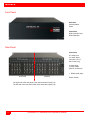
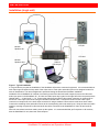
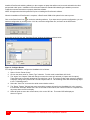
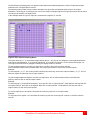
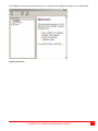
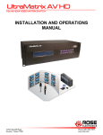
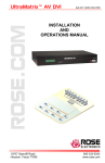
UltraMatrix AV 16x16 AUDIO/VIDEO MATRIX SWITCH INSTALLATION AND OPERATIONS MANUAL 10707 Stancliff Road Houston, Texas 77099 Phone (281) 933-7673 www.rose.com LIMITED WARRANTY Rose Electronics warrants the UltraMatrix™ AV to be in good working order for one year from the date of purchase from Rose Electronics or an authorized dealer. Should this product fail to be in good working order at any time during this one-year warranty period, Rose Electronics will, at its option, repair or replace the Unit as set forth below. Repair parts and replacement units will be either reconditioned or new. All replaced parts become the property of Rose Electronics. This limited warranty does not include service to repair damage to the Unit resulting from accident, disaster, abuse, or unauthorized modification of the Unit, including static discharge and power surges. Limited Warranty service may be obtained by delivering this unit during the one-year warranty period to Rose Electronics or an authorized repair center providing a proof of purchase date. If this Unit is delivered by mail, you agree to insure the Unit or assume the risk of loss or damage in transit, to prepay shipping charges to the warranty service location, and to use the original shipping container or its equivalent. You must call for a return authorization number first. Under no circumstances will a unit be accepted without a return authorization number. Contact an authorized repair center or Rose Electronics for further information. ALL EXPRESS AND IMPLIED WARRANTIES FOR THIS PRODUCT INCLUDING THE WARRANTIES OF MERCHANTABILITY AND FITNESS FOR A PARTICULAR PURPOSE, ARE LIMITED IN DURATION TO A PERIOD OF ONE YEAR FROM THE DATE OF PURCHASE, AND NO WARRANTIES, WHETHER EXPRESS OR IMPLIED, WILL APPLY AFTER THIS PERIOD. SOME STATES DO NOT ALLOW LIMITATIONS ON HOW LONG AN IMPLIED WARRANTY LASTS, SO THE ABOVE LIMITATION MAY NOT APPLY TO YOU. IF THIS PRODUCT IS NOT IN GOOD WORKING ORDER AS WARRANTED ABOVE, YOUR SOLE REMEDY SHALL BE REPLACEMENT OR REPAIR AS PROVIDED ABOVE. IN NO EVENT WILL ROSE ELECTRONICS BE LIABLE TO YOU FOR ANY DAMAGES INCLUDING ANY LOST PROFITS, LOST SAVINGS OR OTHER INCIDENTAL OR CONSEQUENTIAL DAMAGES ARISING OUT OF THE USE OF OR THE INABILITY TO USE SUCH PRODUCT, EVEN IF ROSE ELECTRONICS OR AN AUTHORIZED DEALER HAS BEEN ADVISED OF THE POSSIBILITY OF SUCH DAMAGES, OR FOR ANY CLAIM BY ANY OTHER PARTY. SOME STATES DO NOT ALLOW THE EXCLUSION OR LIMITATION OF INCIDENTAL OR CONSEQUENTIAL DAMAGES FOR CONSUMER PRODUCTS, SO THE ABOVE MAY NOT APPLY TO YOU. THIS WARRANTY GIVES YOU SPECIFIC LEGAL RIGHTS AND YOU MAY ALSO HAVE OTHER RIGHTS WHICH MAY VARY FROM STATE TO STATE. NOTE: This equipment has been tested and found to comply with the limits for a Class A digital device, pursuant to Part 15 of the FCC Rules. These limits are designed to provide reasonable protection against harmful interference when the equipment is operated in a commercial environment. This equipment generates, uses, and can radiate radio frequency energy and, if not installed and used in accordance with the instruction manual, may cause harmful interference to radio communications. Operation of this equipment in a residential area is likely to cause harmful interference in which case the user will be required to correct the interference at his own expense. IBM ®, AT, and PS/2 are trademarks of International Business Machines Corp. Microsoft ® and Microsoft Windows™ are registered trademarks of Microsoft Corp. Apple, Macintosh, and ADB are trademarks of Apple Computer, Inc. Sun is a registered trademark of Sun MicroSystems Inc. Any other trademarks mentioned in this manual are acknowledged to be the property of the trademark owner. Copyright Rose Electronics 2007. All rights reserved. No part of this manual may be reproduced, stored in a retrieval system, or transcribed in any form or any means, electronic or mechanical, including photocopying and recording, without the prior written permission of Rose Electronics. Rose Electronics Part # MAN-UMAV Printed In the United States of America Revision 1.2 INTRODUCTION Contents Page Disclaimer............................................................................................................................................................................. 1 Introduction........................................................................................................................................................................... 1 Features ............................................................................................................................................................................ 1 Installation (single unit) ........................................................................................................................................................ 3 Installation (multiple units) .................................................................................................................................................... 7 Operating UltraMatrix AV ..................................................................................................................................................... 9 Macro’s ............................................................................................................................................................................... 10 Safety ................................................................................................................................................................................. 13 Safety and EMC Regulatory Statements ........................................................................................................................ 13 Service Information ............................................................................................................................................................ 14 Maintenance and Repair ................................................................................................................................................ 14 Technical Support ........................................................................................................................................................... 14 Figures Page Figure 1. Typical Installation ................................................................................................................................................ 3 Figure 2. Configure Router ................................................................................................................................................... 4 Figure 3. Rose Control Switching Matrix .............................................................................................................................. 5 Figure 4. Multiple Unit Installation ........................................................................................................................................ 7 Figure 5. Configure Router (Multiple units) .......................................................................................................................... 7 Figure 6. RoseControl 16x32 ............................................................................................................................................... 8 Figure 7. Operating the RoseControl Matrix ........................................................................................................................ 9 Figure 8. Macros ................................................................................................................................................................ 10 Figure 9. Help menu ........................................................................................................................................................... 11 Appendices Page Appendix A – General Specifications ................................................................................................................................. 15 INTRODUCTION Disclaimer While every precaution has been taken in the preparation of this manual, the manufacturer assumes no responsibility for errors or omissions. Neither does the manufacturer assume any liability for damages resulting from the use of the information contained herein. The manufacturer reserves the right to change the specifications, functions, or circuitry of the product at any time without notice. The manufacturer cannot accept liability for damages due to misuse of the product or other circumstances outside the manufacturer’s control. The manufacturer will not be responsible for any loss, damage, or injury arising directly or indirectly from the use of this product. (See limited warranty) Introduction ® Thank you for choosing Rose Electronics UltraMatrix AV™ for your audio and VGA video switching requirements. The UltraMatrix AV is designed especially for control rooms, audio/video presentations, security centers and many other digital media applications. The ease of switching audio and video sources makes the UltraMatrix AV a versatile and flexible addition to your system. Up to 16 video sources and 16 audio sources can be switched to any selected output port. The audio is automatically switched with the video source. The video and audio switching can be controlled by an IR controller, the RS232 input using a PC Windows based software or individually controlled at the remote location. The UltraMatrix AV supports resolutions up to 1600 x 1200 (bandwidth – 200 MHz) for high quality imagery and video and full stereo audio with a frequency response of 20Hz to 20 KHz. Repetitive switching sequences can be recorded and saved in 1 of 50 macros for playback at any time. Installation consists of two procedures: 1. Connecting the equipment a. Computer videos b. Audio sources 2. Installing the access software for controlling the UltraMatrix AV. Each computer’s video is connected using a HD15M to HD15M cable Each computer’s audio is connected using a standard 3.5mm stereo audio cable The access software makes switching the selected input to an output fast and easy. Just click on the input source and then the output destination and the video and audio are instantly switched. The video and audio from a selected input source are switched together to the output destination. Features Switch multiple video and audio signals to multiple monitors and stereo speakers Route stereo audio together with the video signal to multiple outputs Supports all video formats (VGA / SVGA / XGA / RGBHV / SOG and others) Video bandwidth of 200MHz Supports resolutions up to 1600 x 1200 Save and playback up to 50 different Macro routing sequences Click and switch intuitive software for audio and video switching Add additional units to increase the number of monitors (up to 64) that can be switched to UltraMatrix AV Installation and Operations Manual 1 MODELS Front Panel Indicators Communication Power Connectors RJ45 controller input RJ45 Expansion Rear Panel Connectors 16- audio input 16- audio output (Standard 3.5 mm Stereo Mini plug) 16 video input 16 video output (HD15F connectors) 1- RS232 serial input OUTPUTS INPUTS The right side of the rear panel is the video and audio inputs (16) The left side of the rear panel is the video and audio outputs (16) 2 UltraMatrix AV Installation and Operations Manual Power / Switch INSTALLATION Installation (single unit) CPU #1 . . . . . CPU #16 Monitor/ Speakers #1 . . . . . Monitor/ Speakers #16 Serial Cable to RS-232 port Figure 1. Typical Installation Control Computer It is a good idea to pre-plan the installation of the UltraMatrix AV and the connected equipment. It is recommended that each video input be labeled to keep track of the video source. Each video and audio input can be assigned a name for ease of identification. The name assignment is performed during the RoseControl software installation. Installation of the UltraMatrix AV consists of connecting each of the video and audio output sources to the video and audio input ports on the UltraMatrix AV. All video and audio inputs are located on the right half of the rear panel and are labeled video 1 – 16 and audio 1 – 16. Connect the video from the HD15F video output connector on computer #1 to the HD15F video input connector #1 using an HD15M to HD15M cable. Connect the audio from the audio output connector on computer #1 to the audio input connector #1 using a standard 3.5mm male to male stereo audio cable. Connect the remaining video and audio sources to the corresponding video and audio inputs. Keep the video and audio together, meaning computer #1’s video and audio should be connected to the UltraMatrix AV video #1 and audio #1 inputs. When all connections have been made, power up the system. It is recommended that you first power on all monitors, then the UltraMatrix AV unit, then boot each computer. UltraMatrix AV Installation and Operations Manual 3 Install the RoseControl switching software on the computer or laptop that will be used to control and switch the video and optional audio inputs. Installation of RoseControl follows the standard Windows® type installation procedure. Follow the onscreen instructions to properly install the software. NOTE: All equipment should be powered on prior to installing the RoseControl software. When the installation of RoseControl is complete, a RoseControl ICON will be placed in the start-up menu. to invoke the switching software. If you have saved a previous configuration, you can Click on the RoseControl Icon load that configuration by clicking on the “Yes” tab, select the configuration file, and load it to the OSD matrix. If you click on the “No” tab, the “Configure Router” window will display as shown below. Figure 2. Configure Router For a single unit installation, configure the UltraMatrix AV as follows: 1. Select 1 for the “Router Count”. 2. Click on the down arrow for “Router Type” selection. For this model, select Matrix AV 16x16. 3. The “Inputs” and “Outputs” fields will change to match the router type selected (16 inputs and 16 outputs) These fields can be manually changed to any value from 1 to 16. If you have 4 video input sources to switch to 8 displays, change the inputs field to 4 and the outputs field to 8. The switching matrix will automatically adjust to a 4 x 8 switching matrix. 4. Select the “Com Port” to connect the serial communication cable to. 5. The “Router Timeout” field set how many seconds the program will wait for the UltraMatrix AV unit to respond to commands. Example: 2.5 will wait 2 and 1/2 seconds. If 0 is entered, the unit will not wait for a response and any errors that occur will not display. 6. When all fields are set to the correct values, click on the “OK” tab. The matrix OSD will display as shown in Figure 3. 4 UltraMatrix AV Installation and Operations Manual The RoseControl switching matrix is a dynamic matrix that will automatically adjust the number of inputs and outputs selected on the “Configure Router” screen. The switching matrix makes it easy to select and switch any input video and optional audio source to any output destination. By clicking on a cross-point, you can route a single or multiple outputs to a single input source but an output can only be connected to one input source. In the example shown in Figure 3, Input 04 is connected to output 03, 07, and 08. Figure 3. Rose Control Switching Matrix The input names (In 01 – In 16) and the Output Names (Out 01 – Out 16) can be changed to a name that identifies the video source and destination. In 01 could be videofeed1, In 03 could be Computer 6, In 04 could be DVR player, etc. The output names can also be changed to identify the display location or function. To select multiple outputs to connect to a single input, hold the control (Ctrl) key down and click on the individual output numbers needed. Next, click on the input number to route to the selected outputs. Example: To route outputs 1, 3, 5, 7, and 16 to input #2, hold down the control key, click on the output numbers 1, 3, 5, 7, and 16. When all outputs are selected, click on input number 2. To select multiple adjacent outputs to connect to a single input, click on the first output number, hold down the shift key, and then click on the last output number. Example: To route outputs 1-5 to input #3 and outputs 7-12 to input #7, click on output number 1, hold down the shift key and click on output number 5, then click on the input #3. Next click on output number 7, hold down the shift key and click on output number 12, then click on the input #7. To route a single input to all outputs, hold down the control key and click on an input number. Example: To route input #7 to outputs 1-16, hold down the control key and click on the input #7. Outputs 1-16 will be routed to input #7. UltraMatrix AV Installation and Operations Manual 5 On the right side of the RoseControl switching matrix there are up to 50 macro tabs that are used to save and play back macros. These macros store a set sequence of routes. To record a macro: 1. Click on the Record button. A blinking “recording” message below this button will be displayed to indicate that all routes are being recorded. 2. Select the desired cross points. There is no limit on the number of routes you may record. 3. If you click a macro button while in the record mode, the macro will be executed, and these routes will be added to the recording. This makes it possible to combine the routes of two or more macros into one bigger macro. 4. When finished, click the “Save Macro” button. You will be instructed to then click on one of the macro buttons. Doing this will save the recorded routes to that button. To cancel saving the macro, click the “Cancel Save” button. 5. To play back a macro, simply click on one of the 50 macro buttons. Use the scrollbar to bring any of these into view. 6. The macros are automatically saved in the current configuration file. They are also saved when you select the File/Save Configuration... menu. NOTE: A macro is temporarily saved in the macro tabs (1-50) for the current session. If power is cycled or removed, all macro settings are lost. To permently save the macro and session settings, click on “File” and choose “Save Configuration” or “Save Configuration As” and save the session and all macro information to a file on the controlling computer. 6 UltraMatrix AV Installation and Operations Manual Installation (multiple units) The installation of multiple units consists of one designated master unit and one or more secondary units. All secondary units must have the frame address set for the unit by the factory. The master unit will have a frame address of “0x00”, the secondary units will have a frame address of “0x01”, “0x02”. Etc. The frame address is used when switching ports using RoseControl software or via serial HEX commands sent to the units. (See serial control for instructions) To install and control multiple units, you will need a VGA “Y” cable to connect from the computer’s video port to unit #1 and unit #2’s VGA input ports. An audio “Y” cable is needed if your units have the audio switching option. Also a serial “Y” cable is connected from the controlling computer or laptop to each unit’s RS232 port. When connecting the VGA and optional audio “Y” cables, connect both the VGA and audio cables to the same port number on the master and the secondary unit. (Computer #1 video to the master video port #1 and the secondary video port #1) Secondary unit Master Unit Controlling Laptop with RoseControl Software installed 1 of 16 computers Figure 4. Multiple Unit Installation Install RoseControl software on the controlling computer and start the program. Configure the unit as shown in Figure 5. Figure 5. Configure Router (Multiple units) UltraMatrix AV Installation and Operations Manual 7 1. 2. 3. 4. 5. Select 2 for the “Router Count”. Select AV-16x16 for “Router Type 00”. Select AV-16x16 for “Router Type 01” Select the “Com Port” to connect the serial communication cable to. The “Router Timeout” field set how many seconds the program will wait for the UltraMatrix AV unit to respond to commands. Example: 2.5 will wait 2 and 1/2 seconds. If 0 is entered, the unit will not wait for a response and any errors that occur will not display. 6. When all fields are set to the correct values, click on the “OK” tab. The matrix OSD will display as shown in Figure 6 Figure 6. RoseControl 16x32 The RoseControl switching matrix will display a 16 in by 32 out matrix. Use the bottom scroll bar to display outputs 1-32. Outputs 1-16 are the Master unit outputs and outputs 17-32 and the secondary unit outputs. To switch the input #1 video source to output #2 on the master and secondary units, click on the cross-point In 01, Out 02 and In01, Out 17. This switches the video source on the master and secondary units to the input #1 port and the destination on the master and secondary unit to output port #2. This configuration routes a single video source to two output destinations, one on the master unit and one on the secondary unit. The output destination pairs are 1 and 16, 2 and 17, 3 and 18, … 16 and 32. You can switch a single video source to a single output port by not selecting the output port on the master (1-16) or the secondary (17-32) unit. 8 UltraMatrix AV Installation and Operations Manual Operating UltraMatrix AV Operating the UltraMatrix AV is performed from a standalone computer or laptop connected via a serial cable (single unit installation) or serial “Y” cable (multiple unit installation) to the unit’s RS232 port. RoseControl software is used for all video source selection and destination routing. Inputs are listed vertically and outputs horizontally. Routing a video source to a destination monitor is performed by clicking on the input / output cross-point. You can also route a video source to a destination by first clicking on the output numbered tab across the top of the matrix, then click on an input numbered tab on the left side of the matrix. Input and output names can be changed by highlighting the name and entering the new name. A video source can be routed to one, two or all outputs, but an output can only be connected to a single input. Figure 7. Operating the RoseControl Matrix Multiple adjacent output selection To select multiple outputs that are next to each other, click on one output, then hold down the shift key and select the last output. The output range will be selected as shown above. Next click on the input to route to all the selected outputs. Multiple non-adjacent output selection To select multiple outputs, hold down the control key and select the needed outputs. The selected outputs will all be selected. Next click on the input to route to the selected outputs. To route a single input to all outputs, hold down the control key and click on the input tab number. UltraMatrix AV Installation and Operations Manual 9 Macro’s The UltraMatrix AV can save custom routing schemes as macros. Up to 50 different macros can be created and saved for use at anytime with a single click. Figure 8. Macros To create a macro, click on the Record tab. A dialog box will display showing two choices, “Manual Save” or “Save Status”. If you already have a video routing scheme laid out and want to save it as a macro, click on “Save Status” tab and follow the on-screen instructions. If you are designing a routing scheme and want to record and save the scheme as a macro, click on the “Manual Save” tab. A blinking “Recording” message will display indicating that all routing selections are being recorded. When the assignment is complete, click on a Macro tab on the right and save the macro to that macro position. The RoseControl matrix can be customized to conform to your system set-up. If your system has 12 video sources and these will be displayed on 6 monitors, the matrix can be customized to be a 12 x 6 matrix. Select the Router Type AV-16x16, change the Inputs to 12 and the Outputs to 6 and click on OK. The RoseControl matrix will automatically adjust to a 12 x 6 matrix as shown. 10 UltraMatrix AV Installation and Operations Manual The UltraMatrix AV has a very useful Help function. Clicking on Help will display the help menu as shown below. Figure 9. Help menu UltraMatrix AV Installation and Operations Manual 11 The UltraMatrix AV can be instructed to switch any video input port to any video output port by sending a serial command to the RS232 port. The serial HEX packet format that is sent to the UltraMatrix AV has the following structure: <Header Byte 0><Header Byte 1><Frame Address><Reserved><Source><Destination><Data Bytes><BCC> <Header Byte 0> <Header Byte 1> <Frame Address> <Reserved> <CMD> <Data Bytes> <BCC> Always 0xBE Always 0xEF Frame address set by the manufacture Always 0x00 - Reserved for future use Command byte Number of bytes for the associated CMD XOR of all bytes in the string except the BCC byte Set the communication program up with the below settings. The program must be capable of sending HEX commands to the unit. Baud Rate Start Bits Data Bits Parity Stop Bits 9600 1 8 None 1 Example: The command to switch input #1 to output #1 for the main unit with a frame address of 00 is: BE EF 00 00 00 00 00 51 To calculate the BCC HEX value, convert each byte to its binary equivalent as shown below BE EF 00 00 00 00 00 10111110 11101111 00000000 00000000 00000000 00000000 00000000 -------------XOR result 01010001 Hex equivalent 5 1 To arrive at the XOR result, look at each column and note the number of 1s. If there is an even number of 1s or all zeroes in a column, the result for that column is zero. The result is 1 if there is an odd number of 1s in the column. To set input #2 to output #1 for the main unit with a frame address of 00 is: 0xBE 0xEF 0x00 0x00 0x00 0x01 0x00 0x50 BE EF 00 00 00 01 00 10111110 11101111 00000000 00000000 00000000 00000001 00000000 -------------XOR result 01010000 Hex equivalent 5 0 12 UltraMatrix AV Installation and Operations Manual SAFETY Safety The UltraMatrix AV has been tested for conformance to safety regulations and requirements, and has been certified for international use. Like all electronic equipment, the UltraMatrix AV should be used with care. To protect yourself from possible injury and to minimize the risk of damage to the Unit, read and follow these safety instructions. Follow all instructions and warnings marked on this Unit. Except where explained in this manual, do not attempt to service this Unit yourself. Do not use this Unit near water. Assure that the placement of this Unit is on a stable surface. Provide proper ventilation and air circulation. Keep connection cables clear of obstructions that might cause damage to them. Use only power cords, power adapter and connection cables designed for this Unit. Keep objects that might damage this Unit and liquids that may spill, clear from this Unit. Liquids and foreign objects might come in contact with voltage points that could create a risk of fire or electrical shock. Do not use liquid or aerosol cleaners to clean this Unit. Always unplug this Unit from its electrical outlet before cleaning. Unplug this Unit refer servicing to a qualified service center if any of the following conditions occur: The connection cables are damaged or frayed. The Unit has been exposed to any liquids. The Unit does not operate normally when all operating instructions have been followed. The Unit has been dropped or the case has been damaged. The Unit exhibits a distinct change in performance, indicating a need for service. Safety and EMC Regulatory Statements Safety information Documentation reference symbol. If the product is marked with this symbol, refer to the product documentation to get more information about the product. WARNING CAUTION A WARNING in the manual denotes a hazard that can cause injury or death. A CAUTION in the manual denotes a hazard that can damage equipment. Do not proceed beyond a WARNING or CAUTION notice until you have understood the hazardous conditions and have taken appropriate steps. Grounding These are Safety Class I products and have protective earthing terminals. There must be an un-interruptible safety earth ground from the main power source to the product’s input wiring terminals, power cord, or supplied power cord set. Whenever it is likely that the protection has been impaired, disconnect the power cord until the ground has been restored. Servicing There are no user-serviceable parts inside these products. Only service-trained personnel must perform any servicing, maintenance, or repair. The user may adjust only items mentioned in this manual. UltraMatrix AV Installation and Operations Manual 13 SERVICE and MAINTENANCE Service Information Maintenance and Repair This Unit does not contain any internal user-serviceable parts. In the event a Unit needs repair or maintenance, you must first obtain a Return Authorization (RA) number from Rose Electronics or an authorized repair center. This Return Authorization number must appear on the outside of the shipping container. See Limited Warranty for more information. When returning a Unit, it should be double-packed in the original container or equivalent, insured and shipped to: Rose Electronics Attn: RA__________ 10707 Stancliff Road Houston, Texas 77099 USA Technical Support If you are experiencing problems, or need assistance in setting up, configuring or operating your UltraMatrix AV, consult the appropriate sections of this manual. If, however, you require additional information or assistance, please contact the Rose Electronics Technical Support Department at: Phone: (281) 933-7673 E-Mail: [email protected] Web: www.rose.com Technical Support hours are from: 8:00 am to 6:00 pm CST (USA), Monday through Friday. Please report any malfunctions in the operation of this Unit or any discrepancies in this manual to the Rose Electronics Technical Support Department. 14 UltraMatrix AV Installation and Operations Manual Appendix A – General Specifications Video Video Bandwidth 200MHz Video Input Signal Level 1 Volt pk-pk into 75R Output Impedance 100 Ohms Input Impedance 75 Ohms Resolution Up to 1600 x 1200 Video Connector HD15F Audio Signal 15KHz 0db unbalanced 10K Ohms Frequency Response 20 Hz to 20 KHz, +/- 0.5db Audio Connector 3.2mm Stereo Jack (Input and Output Power Voltage 90 – 230 VAC, 1A, 50/60 Hz Physical Dimensions 19” W x 11.3” D x 5.2” H (482mm W x 287mm D x 133mm H Weight 8.8 lbs (4kg) 10707 Stancliff Road Houston, Texas 77099 Phone (281) 933-7673 www.rose.com