1
P/N: 59033051E002
Copyright © 2007. All rights reserved. No warranty of any kind is made in regard to this material, including, but not limited to, implied warran ties of merchantability or fitness for any particular purpose. We are not liable for any errors contained herein nor for incidental or consequential damages in connection with furnishing, performance or use of this material. We shall be under no liability in respect of any defect arising from fair wear and tear, wilful damage, negligence, abnormal working conditions, failure to follow the instructions and warnings, or mis use or alteration or repair of the products without written approval. No part of this document may be repro duced, transmitted, stored in a retrieval system, transcribed, or translated into any human or computer or other language in any form or by any means electronic, mechanical, magnetic, optical, chemical, biologi cal, manual or otherwise, except for brief passages which may be quoted for purposes of scholastic or lit erary review, without express written consent and authorization. We reserve the right to make changes in product design without reservation and without notification. The material in this guide is for information only and is subject to change without notice. All trademarks mentioned herein, registered or otherwise, are the properties of their various, ill, assorted owners. General handling precautions • • • • • Do not dispose of the scanner in fire. Do not put the scanner directly in the sun or by any heat source. Do not use or store the scanner in a very humid place. Do not drop the scanner or allow it to collide violently with other objects. Do not take the scanner apart without authorization.
i Table of Contents 1 2 3 4 5 6 7 8 9 10 11 12 13 Introduction......................................................................... 1 Scanner and Accessories ................................................... 2 Quick Start.......................................................................... 3 Connecting to a Host .......................................................... 3 Disconnecting the Cable from the Scanner ....................... 4 How to Scan ...................................................................... 4 6.1 Scanning in Handheld mode ...................................... 4 6.2 Scanning in Stand mode ............................................ 5 Scanner Outline ................................................................ 5 Assembling the Optional Stand........................................... 6 Visible Indicators................................................................. 7 Sound Indicators................................................................. 7 Troubleshooting .................................................................. 8 Configuration Modes........................................................... 8 12.1 Barcodes .................................................................. 8 12.2 Zset......................................................................... 8 12.3 Serial Programming ................................................. 9 Programming Guide .......................................................... 9 13.1 Programming Options .............................................. 9 13.2 Default Parameters ................................................ 9 13.3 Factory Default Setting............................................. 10 13.4 Default Data Transmit Format .................................. 11 13.5 Program Procedure Using Barcode Manual............. 11 13.6 Parameter setting..................................................... 12 System function setting ............................................ 12 Scan function setting................................................ 13 Operation function setting ........................................ 15 Interface settings 1. RS232 interface setting .................................... 16 2. Keyboard wedge setting .................................... 18 3. USB interface setting ......................................... 20 4. Wand emulation setting ..................................... 21 The symbologies ...................................................... 22 Full ASCII code 39 table........................................... 36
ii iii
1 Introduction With an impressive scanning speed, this scanner is a highspeed single line laser handheld scanner that brings about the most effective scanning capability any handheld scanner offers. Guaranteed to bring in efficiency for any retail, office or warehouse environment, it is also enhanced through the builtin Z SCAN decoding technology. This one of a kind technology provides realtime scanning and hardware decoding capability that ensures an unbeatable first read success rate. Ergonomically designed, this handheld scanner is available in two different scan engines to choose from. Compared to other similar products on the market, both versions guarantee an impressive, fast and accurate first read success rate. It automatically reads and interprets the world’s most popular 1D barcodes. Either scanners pledge highreliability and superior performance. This slender and lightweight handheld scanner is ruggedly encased. Its durable trigger switch is sturdy enough to withstand heavy usage. The LED display and beeper are programmable to cater to the users’ own preference. Equipped with multiinterface communication, the scanner has an outstanding scanning performance that promises to help you achieve boundless possibilities.
1 2 Scanner and Accessories The highspeed single line laser handheld scanner package contains: 1 ea. single line laser handheld scanner 1 ea. Communication Cable 1 ea. Power Adapter (only for specific RS232 cables) 1 ea. User’s Manual (this book) 1 ea. Optional scanner stand If any contents are damaged or missing, please contact your dealer immediately. Please leave this Users’ Manual within easy access of person using the scanner.
2 3 Quick Start 1. Connect the 10pin RJ45 male connector into the jack on the scanner. When the connection is made, a “click” will be heard. If the scanner is powered directly from the Host supply, skip to step 4. 2. Connect the Lshaped plug of the power supply into the power jack on the cable. 3. Connect the power supply into an AC outlet. Double check that the AC input requirement of the power supply match the AC outlet. 4. Connect the communication cable to the host (refer to your host manual to locate the correct port.) 5. Turn on the Host system. 6. Once the scanner is properly installed, the red, green, and blue LED will turn on. 4 Connecting to a Host 1. Turn off the host system. 2. Connect the 10pin RJ45 male connector into the jack on the scanner. When the connection is made, a “click” will be heard. If the scanner is powered directly from the host supply, skip to step 5. 3. If it is necessary, plug the Lshaped plug of the power supply into the power jack on the cable. 4. Connect the power supply into an AC outlet. (Double check that the AC input requirements of the power supply match the AC outlet.) 5. Connect the cable to the proper port on the host system. 6. Turn on the host system. 7. If the scanner is properly installed, the redgreenblue LED will turn once and 3 powerup beep will be heard. 8. Set the scanner to communicate with your particular POS terminal by scanning the appropriate bar codes. The programming varies on different terminals, for more information consult chapter 13. 9. Verify that the scanner is successfully reading bar codes and transmitting the correct content to the terminal.
3 5 Disconnecting the Cable from the Scanner Prior to removing the cable from the scanner, it is highly advised that the power of the host system is turned off, and power supply disconnected from the cable. 1. Locate the small hole at the bottom of the scanner. 2. Use a metallic pin and insert into the hole. 3. Gently pull the strainrelief of the cable once a faint “click” is heard. 6 How to Scan There are two ways of scanning a bar code. One method is through “Handheld Mode” and the other is through “Stand Mode.” The following explains how these can be achieved. 6.1 Scanning in Handheld mode 1. When the scanner is removed from the stand, the trigger scan is activated. 2. Press the trigger and aim at the bar code. 3. When decoding is successful, the scanner beeps and the LED indicate blue/green. 6.2 Scanning in Stand mode 1. The blue LED will blink when the scanner is placed on the optional presentation stand. This indicates that the Stand mode scanning is activated. 2. Present the bar code in the scan field. 3. The bar code will automatically be decoded and transmitted.
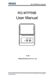
4 7 Scanner Outline Blue LED Red LED Cable Connection Green LED Trigger Pin Hole Exit Window Buzzer Sound Hole
5 8 Assembling the Optional Stand The optional selfsupporting stand is to facilitate the usage of your scanner. It moves freely and can be placed anywhere on countertops. It can be tilted to a maximum of 60 degrees. 60° To attach the scanner to the optional stand, hook the scanner on the two holes located at the front of the stand.
6 9 Visible Indicators There are three (blue) LED indicator bars and two (green/red) LED indicators on top of the scanner. These indicate the operational status of the scanner. LED Status Blue, Red, and Green LEDs are off LED Indication These LED will not be on if the scanner has no power from the host or transformer. When the scanner is in standby mode, the trigger button is enabled. Present a barcode to the scanner and the red LED will turn on when the laser is turned on. Steady Blue, Red, and Green The scanner is in Bootload Mode (firmware upgrade status) Steady Red When the laser is active, the red LED is on. The red LED will remain on until the laser is deactivated. Single Green and Blue Flash Steady Green A barcode has been successfully decoded. Steady Red/Green This indicates the scanner has a motor or laser failure. A beep is heard when a motor failure occurs. Return the unit for repair. Constant Blue Flashes While the scanner is on the stand, the laser will turn on (along with the red LED) when a barcode is presented in the scan field. The barcode will be automatically decoded and transmitted. Alternate Red and Green Flashes The scanner detects a power failure. Please check whether the power is properly connected. 10 A barcode has been successfully decoded, but the object is not removed from the scan window. The scanner is in programming mode. Sound Indicators When the scanner is in operation, it provides audible feedback. The beeps indicate the status of the scanner. Beep One Beep Indication A barcode has been successfully decoded. Three Consequent Beeps This indicates that the scanner has passed the selftest and is operating properly. When the scanner is powered up. Two Consequent Beep This indicates that the scanner is in programming mode. Continuous Beep Tone This is a failure indication. Return the unit for repair.
7 11 Troubleshooting Problem The scanner has no reaction; no LED, beeps, or laser The scanner is functioning but it is not decoding. Possible Cause The power is not ON Solution Refer to the “Quick Start” section of the manual The label of the barcode might be disabled. The number of characters of the barcode label does not match the initial setting. Enable the barcode type from the programming guide. Adjust the label length setting of the barcode type. When using the KBW interface, the data transmission is slower than usual A barcode is read but not accepted by the host device. The system is not compatible with the international ALT method. Under properties, select the language property that is suitable for your keyboard. Either a wrong interface is selected or the interface is incorrectly set. Check the interface, cable used and its settings. Alternating red and green flashes There is a power failure in this scanner. Please check and see if the power is properly connected. Steady red/green LED There is a laser failure in the scanner. Immediately power off the scanner and return the unit for repair. Characters are being dropped. The delay time in the inter character needs to be increased. Adjust the character delay time. 12 Configuration Modes This scanner has three programming modes. 12.1 Barcodes This scanner can be configured by scanning the bar codes located under the “Programming Guide” section. Please refer to this guide for instructions. 12.2 Serial Programming This mode gives endusers the ability to send a series of commands using the serial port of the host system. For more information, please contact your dealer.
8 13 Programming Guide Scanning a series of programming bar code labels can configure the series scanners. This allows decoding options and interface protocols to be tailored to a specific application. The configuration is stored in nonvolatile memory and will not be lost by removing power from the scanner. The scanner must be properly powered before programming. For RS232C type scanners, an external power adapter must be used to supply DC power to the scanner. If a keyboard emulation type scanner is used with an IBM PC/XT/ AT, PS/2 or any fully compatible computers, power will be drawn from the key board port. No external power adapter is required. If keyboard emulation type scanner is used with any other non IBM PC compatible computers, an external power adapter may be needed. During the programming mode, the laser scanner will acknowledge a good and valid reading with a short beep. It will give long beeps for either an invalid or bad reading. 13.1 Programming Options Programmable options are divided into four groups. The first group includes the options that show the general behavior of the laser scanner. The second group governs the operation of RS232C type serial ports. The third group selects the keyboard type that the keyboard emulation type will be emulated. The last group sets the decoding parameters for each barcode symbology. 13.2 Default Parameters This table gives the default settings of all the programmable parameters. The default settings will be restored whenever the "Reset" programming label is scanned and the laser scanner is in programming mode.
9 13.3 Factory Default Setting Scanner Timing Same code delay RS232 communication Baud rate Parity Data Bits Stop Bit RTS/CTS Terminator Keyboard Wedge Communication Terminal Type Keyboard Terminator USB Communication Terminator type Code mode Keyboard Wand Emulation Wand emulation speed Data output Decoder Selection EAN/UPC CODE 39 Code 32 CODABAR ITF 2 OF 5 MSI Chinese Post code Code 93 Code 128 EAN128 Beeper sound Frequency Duration Led/Beep Before transmission Operating parameter Trigger mode(handheld mode) Stand mode Header and Trailer InterMessage delay Inter character delay Code Identifiers Identifier code as ZEBEX standard Identifier code as AIM standard Code 39 identifier code ITF 2 of 5 identifier code Chinese post code identifier code UPCA identifier code UPCE identifier code EAN13 identifier code EAN8 identifier code Codabar identifier code Code 128 identifier code Code 93 identifier code MSI identifier code Default 500msec Default 9600 none 8 1 off <CR><LF> Default PC/AT US keyboard Enter(Alpha numeric) Default Enter Scan code US keyboard Default Normal Black=high Default Enable Enable disable Disable Enable disable disable Enable Enable Disable Default Medium 100msec On Default Enable Enable None None None Default Disable Disable M I H A E F FF N K L P
10 13.4 Default data transmit format Code Message format D1 D2 D3 D4 D5 D6 D7 D8 D9 D10 D11 D12 D13 D1 D2 D3 D4 D5 D6 D7 D8 D1 D2 D3 D4 D5 D6 D7 D8 D9 D10 D11 D12 D1 D2 D3 D4 D5 D6 D7 D8 D1Dx (default 3~62) ]C1 D1Dx (default 3~62) D1Dx (default 3~62) D1Dx (default 6~32) D1Dx (default 6~32) D1Dx (default 8~32) D1Dx (default 3~32) D1Dx (default 6~32) EAN13 EAN8 UPCA UPCE CODE128 EAN128 CODE39 CODABAR INTERLEAVED 2/5 CHINESE POST CODE CODE93 MSI 13.5 Program Procedure Using Barcode Manual START
Read Start of Configuration Label Set All Defaults Set Operating Parameters Set Serial Port Parameters Set Keyboard Type Finish Discard Read End of Configuration Label Read Abort Label END 11 Set Decoding Parameters 13.6 Parameter setting Note: Default values are highlighted in grey background. Start Of Configuration System Function Setting Barcode Value Description Reset (return to factory default) Display firmware version Return as customer default Save as customer default Return to USB default Return to wand emulation default Return to RS232 default IBM PC/AT/PS/2 Keyboard emulation Abort (exit programming mode(no update) End Of Configuration
12 Start Of Configuration Scan Function Setting Handheld Operation Trigger mode Ÿ The scanner becomes inactive as soon as the data is transmitted. It must be triggered to become active again. Pulse mode Ÿ This scanner will light up and blink when press the scanner trigger switch once. And, the scanner will turn off for next pressing. The laser remains on for approximately 3 to 10 second after enter Pulse light Auto trigger mode. Ÿ The mode is auto object detect to active laser. Bar code data is transmitted when the trigger button is pressed. Note: Not all models support this function setting. Aim mode. Ÿ Normal is pulse mode but Bar code data is transmitted when the trigger button is pressed Momentary mode. Ÿ The scanner will light up only when the trigger switch is pressed. The scanner will turn off when the trigger switch is released. Flash on/off timeout duration Medium Fast Slow End Of Configuration
13 Start Of Configuration Scan Function Setting (continued) Stand Operation Auto scan in stand mode. Ÿ Auto object detect to active laser and bar code is automatically decoded and transmitted. (Specific models only) Ÿ Always active pulse laser when order without object sensor version Stand by manual trigger Scan Angle Change (for specific models only) Wide scan angle mode Reduced scan angle mode Same Code Delay 50msec 100msec 200msec 300msec 400msec 500msec 600msec 700msec 800msec 1000msec Infinite End Of Configuration
14 Start Of Configuration Operation Function Setting Good Read Beeper Tone Selection Medium beeper tone Low beeper tone High beeper tone Speaker disable Beeper Sound Selection Long Medium Short Ultra Short Ultra Long Loud Volume Medium Volume Slight volume Poweron tone Poweron tone enable disable LED/Beep after transmission. Ÿ Use this bar code to indicate a "good read" after a bar code has been successfully decoded. LED/Beep before transmission Ÿ Use this bar code to indicate a good read" after successfully transmitting the bar code data to the host.
Inter Character Delay 0ms 2ms 5ms 10ms 20ms 50ms End Of Configuration
15 Start Of Configuration Inter Message Delay 0 ms 100 ms 500 ms 1000 ms Interface Settings 1. RS232C Interface Setting Baud Rate 115200 19200 9600 4800 2400 1200 Parity Bit Even parity Odd parity Mark parity Space parity None parity Stop Bit 1 stop bit 2 stop bit Data Bit 7 data bit 8 data bit End Of Configuration
16 Start Of Configuration Handshaking Protocol None handshaking ACK/NAK Xon/Xoff RTS/CTS Enable BEEPER ON<BEL> CHARACTER Ignore BEEP ON <BEL> CHARACTER Disable ACK/NAK timeout beeper Enable ACK/NAK timeout beeper(three sound beeper sound) ACK/NAK response time 300ms ACK/NAK response time 2s ACK/NAK response time 500ms ACK/NAK response time 3s ACK/NAK response time 1s ACK/NAK response time 5s ACK/NAK response time infinity End Of Configuration
17 Start Of Configuration Message Terminator RS232 message terminator—none RS232 message terminator—CR/LF RS232 message terminator—C RS232 message terminator—LF RS232 message terminator—H tab RS232 message terminator—STX/ETX RS232 message terminator—EOT 2. Keyboard Wedge Setting Keyboard Wedge Setting IBM PC/AT/PS/2 Keyboard emulation International Keyboard mode.( ALT method). Keyboard language supportUSA Keyboard language supportUK send scan code Keyboard language supportGERMANY Keyboard language supportFRENCH send scan code End Of Configuration
18 Start Of Configuration Keyboard Wedge Setting (continued) Keyboard language supportSPANISH send scan code Keyboard language supportITALIAN send scan code Keyboard language supportSwitzerland send scan code Keyboard language supportBelgium send scan code Keyboard language supportJapanese Capital lock on Capital lock off Function key emulation enable Function key emulation disable Send number as normal data Send number as keypad data Message Terminator Keyboard terminatornone Keyboard terminatorEnter Keyboard terminatorHTAB End Of Configuration
19 Start Of Configuration 3. USB Interface Setting USB interface International Keyboard mode.( ALT method). Keyboard language supportUSA Keyboard language supportGERMANY Keyboard language supportFRENCH send scan code Keyboard language supportSPANISH send scan code Keyboard language supportJapanese Message Terminator Keyboard terminatornone Keyboard terminatorEnter Keyboard terminatorHTAB End Of Configuration
20 Start Of Configuration 4. Wand Emulation Setting Wand emulation is not supported as standard, if needed, please contact your distributor. Wand Emulation All barcode will be decoded and transmitted in that symbology Enable Wand output data format as CODE39 Wand emulation data output black=high Ÿ Scan this bar code to set quiet zones and spaces low and bars =high. Wand emulation data output black=low Ÿ Scan this bar code to set quiet zones and spaces high and bars=low Idle = high Ÿ Idle state refers to the TTL logic level of the Wand Emulation signal when not in use Idle = low Ÿ Idle state refers to the TTL logic level of the Wand Emulation signal when not in use Wand emulation speedLow Ÿ This option allows the transmission of wand emulation at 1ms narrow element width Wand emulation speedmedium Ÿ This option allows the transmission of wand emulation at 600us narrow element width Wand emulation speednormal Wand emulation speedhigh Ÿ This option allows the transmission of wand emulation at 300us narrow element width Wand emulation speedhigher Ÿ This option allows the transmission of wand emulation at 100 us narrow element width Wand emulation narrow/wide ratio 1:2 Wand emulation narrow/wide ratio 1:3 End Of Configuration
21 Start Of Configuration The Symbologies CODABAR Parameter Setting Codabar enable CODABAR disable Codabar start/stop character transmissionnone Codabar start/stop character transmissionA,B,C,D Codabar start/stop character transmission DC1~DC4 Codabar start/stop character transmission a/t,b/n,c/*,d/e Codabar maximum length setting Codabar minimum length setting Save setting to confirm (for length setting) Codabar concatenation disable Codabar concatenation enable No check character Validate modulo 16,but don’t transmit End Of Configuration
22 Start Of Configuration CODABAR Parameter Setting (continued) Validate modulo 16 and transmit Codabar data redundant check=off Codabar data redundant check=1 Codabar data redundant check=2 Code 39 Parameter Setting Code 39 enable Code 39 disable Code 32 enable Code 32 disable Code 39 data redundant check=off Code 39 data redundant check=1 Code 39 data redundant check=2 Standard code 39 FULL ASCII code 39 Code 39 start/stop character transmission End Of Configuration
23 Start Of Configuration Code 39 Parameter Setting (continued) Code 39 start/stop character without transmission Code 39 check digit calculate and transmit Code 39 check digit calculate but without transmit No check character Code 39 maximum length setting Code 39 minimum length setting Save setting to confirm (for length setting) Code 39 concatenation enable Code 39 concatenation disable Code 32 (Italian pharmacy) transmit “A” character Code 32 (Italian pharmacy) without transmit ”A” character End Of Configuration
24 Start Of Configuration Code 93 Parameter Setting (continued) Code 93 enable Code 93 disable Code 93 data redundant check=off Code 93 data redundant check=1 Code 93 data redundant check=2 Code 93 maximum length setting Code 93 minimum length setting Save setting to confirm (for length setting) Code 93 check digit calculate but without transmit Code 93 check digit not calculate and without transmit Code 93 check digit calculate and transmit End Of Configuration
25 Start Of Configuration Code 128 Code 128 enable Code 128 disable EAN 128 enable EAN 128 disable Code 128 data redundant check=off Code 128 data redundant check=1 Code 128 data redundant check=2 Code128 FNC2 concatenation enable Code128 FNC2 concatenation disable No check character Calculate but not transmitted Save setting to confirm (for length setting) Code 128 maximum length setting Code 128 minimum length setting End Of Configuration
26 Start Of Configuration Chinese Post Code Chinese post code enable Chinese post code disable Chinese post codedata redundant check=off Chinese post code data redundant check=1 Chinese post codedata redundant check=2 Chinese post code maximum length setting Chines post code code minimum length setting Save setting to confirm (for length setting) MSI/PLESSY MSI enable MSI disable MSI data redundant check= off MSI data redundant check=1 MSI data redundant check=2 MSI/PLESSY maximum length setting MSI/PLESSY minimum length setting Save setting to confirm (for length setting) End Of Configuration
27 Start Of Configuration MSI/PLESSY (continued) MSI/Plessy double check digit calculate but not transmit MSI/Plessy double check digit without calculate and transmit MSI/Plessy double check digit calculate but only first digit transmit MSI/Plessy double check digit calculate and both transmit MSI/Plessy single check digit calculate but without transmit MSI/Plessy single check digit calculate and transmit ITF 2 of 5 ITF 2 of 5 enable ITF 2 of 5 disable IATA code enable IATA disable ITF 25 data redundant check=off ITF25 data redundant check=1 ITF25 data redundant check=2 ITF 2 of 5 code maximum length setting End Of Configuration
28 Start Of Configuration ITF 2 of 5 (continued) ITF 2 of 5 code minimum length setting ITF 2 of 5 no check character ITF 2 of 5 check digit calculate and transmit ITF 2 of 5 check digit calculate but without transmit ITF 2 of 5 one Fixed length setting ITF 2 of 5 two Fixed length setting ITF 2 of 5 length variable Save setting to confirm (for length setting) UPC/EAN/JAN EAN convert toISSN/ISBN enable EAN convert to ISSN.ISBN disable UPC/EAN/JAN enable UPC/EAN/JAN disable UPC/EAN/JAN ALL ENABLE EAN8 OR EAN13 ENABLE UPCA AND EAN13 ENABLE End Of Configuration
29 Start Of Configuration UPC/EAN/JAN (continued) UPCA AND UPCE ENABLE UPCA ENABEL UPCE ENABLE EAN13 ENABLE EAN8 ENABEL UPC/EAN Addendum Disable Add on 5 only Add on 2 only Add on 2 or 5 Force UPCE to UPCA format enable Force UPCE to UPCA format disable Force UPCA to EAN13 format enable Force UPCA to EAN13 format disable Transmit UPCA check digit enable Transmit UPCA check digit disable Transmit UPCE leading character enable End Of Configuration
30 Start Of Configuration UPC/EAN/JAN (continued) Transmit UPCE leading character disable Transmit UPCE check digit enable Transmit UPCE check digit disable Transmit EAN8 check digit enable Transmit EAN8 check digit disable Transmit EAN13 check digit enable Transmit EAN13 check digit disable Transmit UPCA leading character enable Transmit UPCA leading character disable Addon format with separator Addon format without separator EAN/UPC +addon (none mandatory) EAN/UPC +addon ( mandatory) EAN/UPC +addon mandatory for 378/379 French Supplement requirement, not sent for other EAN/UPC +addon mandatory for 978/977 (bookland) Supplement requirement, not sent for other End Of Configuration
31 Start Of Configuration UPC/EAN/JAN (continued) EAN/UPC +addon mandatory for 434/439 German Supplement requirement, optionally for other EAN/UPC +addon mandatory for 419/414 Euro amounts Supplement requirement, not sent for other EAN/UPC +addon mandatory for 414/419 Euro Supplement requirement, optionally for other EAN/UPC +addon mandatory for 491 Japanese (bookland) Supplement requirement, not sent for other EAN/UPC +addon mandatory 491 Japanese (bookland) Supplement requirement, optionally for other Disable all EAN/OPC + Addon mandatory for specific country code force EAN8 to EAN13 format enable force EAN8 to EAN13 format disable EAN/UPC +addon mandatory for 414/419/378/379/978/977/434/439/529/ Euro Supplement requirement, optionally for other EAN/UPC +addon mandatory for 414/419/378/379/978/977/434/439/529/ Euro Supplement requirement, not sent for other EAN13 country code first “0” can transmitted EAN13 country code first:”0” can’t transmitted End Of Configuration
32 Start Of Configuration Addendum Seek Timeout Note: A higher timeout value setting offer more assurance that an addendum has been read correctly while a lower setting allows faster scanning performance. Addendum seek timeout value=1 Addendum seek timeout value=2 Addendum seek timeout value=3 Addendum seek timeout value=4 Addendum seek timeout value=5 Addendum seek timeout value=6 Addendum seek timeout value=7 Addendum seek timeout value=8 Addendum seek timeout value=9 Addendum seek timeout value=10 2 digit addendum data redundant check=off 2 digit addendum data redundant check=1 2 digit addendum data redundant check=2 2 digit addendum data redundant check=3 5 digit addendum data redundant check=off End Of Configuration
33 Start Of Configuration Addendum Seek Timeout (continued) 5 digit addendum data redundant check=1 5 digit addendum data redundant check=2 5 digit addendum data redundant check=3 Data Editing Identifier Code Disable identifier code Enable identifier code table as ZEBEX standard Enable identifier code table as AIM standard. CODE 39 identifier code setting ITF 2 of 5 identifier code setting CHINESE POST CODE identifier code setting UPCE identifier code setting UPCA identifier code setting EAN13 identifier code setting EAN8 identifier code setting End Of Configuration
34 Start Of Configuration Identifier Code (continued) CODABAR identifier code setting CODE 128 identifier code setting CODE 93 identifier code setting MSI identifier code setting Save setting to confirm (for length setting) Add code length as header enable (2 Bytes) Add code length as header disable (2 Bytes) Header And Trailer Header (Preamble) Trailer (Postamble) Truncate header character Truncate trailer character End Of Configuration
35 Start Of Configuration Full ASCII Code 39 Table Code 39 ASCII Hexa code Code 39 ASCII Hexa code Full ASCII NUL 00 Full ASCII SI Function key“Shift” 0F Full ASCII SOH Function key“Ins” 01 Full ASCII DLE Function key“5(num)” 10 Full ASCII STX Function key“Del” 02 Full ASCII DC1 Function key“F1” 11 Full ASCII ETX Function key“Home” 03 Full ASCII DC2 Function key“F2” 12 Full ASCII EOT Function key“End” 04 Full ASCII DC3 Function key“F3” 13 Full ASCII ENQ Function key“Up arrow” 05 Full ASCII DC4 Function key“F4” 14 Full ASCII ACK Function key“Down arrow” 06 Full ASCII NAK Function key“F5” 15 Full ASCII BEL Function key“Left arrow” 07 Full ASCII SYN Function key“F6” 16 Full ASCII BS Function key “Backspace” 08 Full ASCII ETB Function key“F7” 17 Full ASCII HT Function key“TAB” 09 Full ASCII CAN Function key“F8” 18 Full ASCII LF Function key“Enter (alpha numeric” 0A Full ASCII EN Function key“F9” 19 Full ASCII VT Function key“right arrow” 0B Full ASCII SUB Function key“F10” 1A Full ASCII FF Function key“PgUp” 0C Full ASCII ESC Function key“F11” 1B Full ASCII CR Function key “Enetr(num.)” 0D Full ASCII FS Function key“F12” 1C Full ASCII SO Function key“PgDn” 0E Full ASCII GS Function key“ESC” 1D End Of Configuration
36 Start Of Configuration Full ASCII Code 39 Table Code 39 ASCII Hexa code Code 39 ASCII Hexa code Full ASCII RS Function key“CTL(L)” 1E Full ASCII 2D Full ASCII US Function key“ALT(L)” 1F Full ASCII . 2E Full ASCII SP 20 Full ASCII / 2F Full ASCII ! 21 Full ASCII 0 30 Full ASCII “ 22 Full ASCII 1 31 Full ASCII # 23 Full ASCII 2 32 Full ASCII $ 24 Full ASCII 3 33 Full ASCII % 25 Full ASCII 4 34 Full ASCII & 26 Full ASCII 5 35 Full ASCII ‘ 27 Full ASCII 6 36 Full ASCII ( 28 Full ASCII 7 37 Full ASCII ) 29 Full ASCII 8 38 Full ASCII * 2A Full ASCII 9 39 Full ASCII + 2B Full ASCII : 3A Full ASCII , 2C Full ASCII ; 3B End Of Configuration
37 Start Of Configuration Full ASCII Code 39 Table Code 39 ASCII Hexa code Code 39 ASCII Hexa code Full ASCII < 3C Full ASCII K 4B Full ASCII = 3D Full ASCII L 4C Full ASCII > 3E Full ASCII M 4D Full ASCII ? 3F Full ASCII N 4E Full ASCII @ 40 Full ASCII O 4F Full ASCII A 41 Full ASCII P 50 Full ASCII B 42 Full ASCII Q 51 Full ASCII C 43 Full ASCII R 52 Full ASCII D 44 Full ASCII S 53 Full ASCII E 45 Full ASCII T 54 Full ASCII F 46 Full ASCII U 55 Full ASCII G 47 Full ASCII V 56 Full ASCII H 48 Full ASCII W 57 Full ASCII I 49 Full ASCII X 58 Full ASCII J 4A Full ASCII Y 59 End Of Configuration
38 Start Of Configuration Full ASCII Code 39 Table Code 39 ASCII Hexa code Code 39 ASCII Hexa code Full ASCII Z 5A Full ASCII i 69 Full ASCII [ 5B Full ASCII j 6A Full ASCII \ 5C Full ASCII k 6B Full ASCII ] 5D Full ASCII l 6C Full ASCII ^ 5E Full ASCII m 6D Full ASCII _ 5F Full ASCII n 6E Full ASCII ` 60 Full ASCII o 6F Full ASCII a 61 Full ASCII p 70 Full ASCII b 62 Full ASCII q 71 Full ASCII c 63 Full ASCII r 72 Full ASCII d 64 Full ASCII s 73 Full ASCII e 65 Full ASCII t 74 Full ASCII f 66 Full ASCII u 75 Full ASCII g 67 Full ASCII v 76 Full ASCII h 68 Full ASCII w 77 End Of Configuration
39 Start Of Configuration Full ASCII Code 39 Table Code 39 ASCII Hexa code Full ASCII x 78 Full ASCII y 79 Full ASCII z 7A Full ASCII { 7B Full ASCII | 7C Full ASCII } 7D Full ASCII ~ 7E Full ASCII DEL 7F End Of Configuration
40 Part no.: MUL5326201