1
1
2
No warranty of any kind is made in regard to this material, including, but not limited to,
implied warranties of merchantability or fitness for a particular purpose. We are not liable
for any errors contained herein or incidental or consequential damages in connection with
furnishing, performance or use of this material.
No part of this document may be reproduced, transmitted, stored in a retrieval system,
transcribed, or translated into any language or computer language in any form or by any
means electronic, mechanical, magnetic, optical, chemical, manual or otherwise, without
express written consent and authorization.
We reserve the right to make changes in product design without reservation and without
notification. The material in this guide is for information only and is subject to change
without notice.
All trademarks mentioned herein, registered or otherwise, are the properties of their various
respective owners.
Copyright © 2006.
All rights reserved.
Radio Notice
This equipment generates uses and can radiate radio frequency energy. If not installed
and used in accordance with the instructions in this manual, it may cause interference to
radio communications. The equipment has been tested and found to comply with the limits
for a Class A computing device pursuant to EN55022 and 47 CFR, Part 2 and Part 15 of the
FCC rules. These specifications are designed to provide reasonable protection against
interference when operated in a commercial environment.
Radio and Television Interference
Operation of this equipment in a residential area can cause interference to radio or
television reception. This can be determined by turning the equipment off and on. The
user is encouraged to try to correct the interference by one or more of the following
measures:
Reorient the receiving antenna.
Relocate the device with respect to the receiver.
Move the device away from the receiver.
Plug the device into a different outlet so that the device and the receiver are on different
branch circuits.
If necessary the user may consult the manufacturer, and authorized dealer, or experienced
radio/television technician for additional suggestions. The user may find the following
booklet prepared by the Federal Communications Commission helpful: “How to Identify and
Resolve Radio-TV Interference Problems.” This booklet is available from the U.S.
Government Printing Office, Washington, DC 20402 U.S.A., Stock No. 004000003454.
For CE-countries
This scanner is in conformity with CE standards. Please note that an approved,
CE-marked power supply unit should be used in order to maintain CE conformance.
i
Laser Safety
The laser scanner complies with safety standard IEC 60825 -1for a Class I laser produce.
It also complies with CDRH as applicable to a Class IIa laser product. Avoid long term
staring into direct laser light.
Radiant Energy: The laser scanner uses one low-power visible laser diodes operating at
650nm in an opto-mechanical scanner resulting in less than 3.9μW radiated power as
observed through a 7mm aperture and averaged over 10 seconds.
Do not attempt to remove the protective housing of the scanner, as unscanned laser light
with a peak output up to 0.8mW would be accessible inside.
Laser Light Viewing: The scan window is the only aperture through which laser light may
be observed from this product. A failure of the scanner motor, while the laser diode
continues to emit a laser beam, may cause emission levels to exceed those for safe
operation. The scanner has safeguards to prevent this occurrence. If, however, a
stationary laser beam is emitted, the failing scanner should be disconnected from its power
source immediately.
Adjustments: Do not attempt any adjustments or alteration of this product. Do not
remove the protective housing of the scanner. There are no user-serviceable parts inside.
Caution: Use of controls or adjustments or performance of procedures other than those
specified herein may result in hazardous laser light exposure.
Optical: The use of optical instruments with this product will increase the eye hazard.
Optical instruments include binoculars, magnifying glasses, and microscopes but do not
include normal eye glasses worn by the user.
ii
Table of Contents
Introduction........................................................................................... 1
Unpacking............................................................................................. 2
Outline .................................................................................................. 3
Scanner Outline ........................................................................... 4
Stand Outline ............................................................................... 4
Connecting ........................................................................................... 5
Power........................................................................................... 5
Verifying Scanner Operation........................................................ 5
Connecting to the Host ................................................................ 6
Setting Up the Scanner ........................................................................ 7
Scan Test ..................................................................................... 7
Set up........................................................................................... 7
Operating the Scanner ......................................................................... 9
Function Button............................................................................ 9
Presentation Mode............................................................ 9
Multi-line Scan Mode ...................................................... 10
Single-line Scan Mode.................................................... 10
LED Indications...........................................................................11
Beeps .........................................................................................11
Sleep Mode................................................................................ 12
Maintaining the Scanner..................................................................... 13
Troubleshooting.................................................................................. 14
Programming Guide ........................................................................... 15
Programming Options................................................................ 15
Default Parameters.................................................................... 15
Factory Default Setting .............................................................. 16
Default Data Transmit Format.................................................... 17
Program Procedure Using Barcode Manual.............................. 17
Parameter Setting...................................................................... 18
System Function Setting................................................. 18
Scan Function Setting..................................................... 19
Double Field Support ...................................................... 21
Japanese Double Field Support ..................................... 22
Operation Function Setting ............................................. 23
Interface Settings ............................................................ 25
RS-232C Interface Setting ....................................... 25
Keyboard Wedge Setting ......................................... 28
USB Interface Setting............................................... 30
Wand Emulation Setting ........................................... 31
The Symbologies ............................................................ 33
CODABAR Parameter Setting ................................. 33
iii
Code 39 Parameter Setting...................................... 34
Code 93 Parameter Setting...................................... 36
Code 128 .................................................................. 37
Chinese Post Code .................................................. 38
MSI/Plessy................................................................ 39
ITF 2 of 5 .................................................................. 40
UPC/EAN/JAN.......................................................... 41
Addendum Seek Timeout ......................................... 45
Data Editing........................................................................ 46
Identifier Code .......................................................... 46
Header and Trailer.................................................... 47
Full ASCII Code 39 Table ................................................... 48
iv
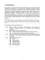
1. Instruction
The scanner, combining with omnidirectional scanning performance and
handheld convenience, it is ergonomically facilitates scanning of large
items that is unable to be presented to any counter-top scanner. It is also
equipped with single line scanning capability and in stand operation with
exclusively designed adjustable stand to benefit for any kind of
applications required. The scanner has a built-in high speed decoder
and instantly decodes any popular 1D symbology and optional in
decoding of RSS group barcodes. It is also equipped with multi-interface
communication, which supports RS-232, keyboard and as well as USB
interface.
The reading status can be checked with the LED indicator, and buzzer.
The scanner operates with +5VDC from Host or external power supply
unit.
The scanner includes key features as,
Button switch in between omnidirectional and single–line
scanning capability, ideal for increasing your operating
efficiency.
Powerful 20-line scan pattern yields
1400 scans per second for omnidirectional scanning
74 scans per second for single-line scanning
Implement with the proprietary real-time hardware decoding
technology that ensures instant recognition and decoding
barcodes
Ideal for applications at:
Retail
Point-of-Sale
Logistic tracking
Administration
Inventory control
Manufacturing
1
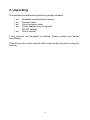
2. Unpacking
The handheld omnidirectional scanner package contains:
1 ea.
1 ea.
1 ea.
1 ea.
1 ea.
Handheld omnidirectional scanner
Scanner stand
Communication cable
Power adapter (only for specific
RS-232 cables)
User’s manual
If any contents are damaged or missing, please contact your dealer
immediately.
Please leave this user’s manual within easy access of person using the
scanner.
2
3. Outline
3-1. Scanner Outline
Buzzer
Exit Window
LED Indicator
Object Detector
Function
button
Buzzer
Scan Trigger
Pin Hole
Cable
Connection
Description
Exit Window
Object Detector
Beeper
Scan Trigger
Pin Hole
LED Indicator
Switching button
Cable Connection
Function
Reads barcodes
Trigger and wake up scanner when
presenting barcode in its range
For beep tone indication
Trigger to make data capture
Use pin to loose interface cable
When power is on, LED turns Red; for a good
read, green light blinks.
Push down to make switch between
single-line and omnidirectional scanning.
For interface communication cable
connection.
3
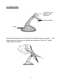
3-2. Stand Outline
Set device into
stand in this
direction
Device Holder
Logo
Gently set the device into the stand in the direction shown by arrow. The
stand supports the device as hands-free mode and it tilts in 36° angle
range shown as below.
4
4. Connecting
4-1. Power
The scanner requires a minimum of 250mA at 5 VDC power. The interface cable
that comes with the scanner supports both direct power (where the scanner takes
power from the host machine) and external power (that’s what the supplied power
adapter is for). A sufficiently robust POS system can support a scanner
successfully without external power; a POS system with a barely adequate power
supply may produce erratic performance (either of the POS system itself, or of the
scanner, or both) when a scanner is attached. Unless you are sure your POS
system can candle such loading, it is recommended that you use the supplied
power adapter. When an external adapter is connected, the scanner does not
take power from the host.
The scanner turns on when power is supplied, and turns off when power is
removed. There is no on/off switch on the scanner itself.
Use only an AC/DC power adapter approved for the scanner. Use of other
power supplies may cause damage to the scanner, and void the factory warranty.
4-2. Verifying Scanner Operation
Please follow the procedure below to verify scanning operation.
1. Insert the 10-pin modular plug of the Interface cable into the scanner
until a firm click is heard.
2. Plug the power adapter into the jack on Interface cable if necessary.
3. Plug the AC end of the power adapter into an AC outlet, or plug the
other end of cable into host if power adapter is not needed. The
scanner powers up, the buzzer sounds four beeps and the LED
indicator glows.
4. Present a known-good test barcode to the scanner. The scanner
should issue a short beep and the LED should flash red momentarily.
[if the scanner is connected to a keyboard wedge for this test, it
should read one barcode, beep, then remain with a red LED
indicating light. This is normal when the keyboard wedge is not
connected to a live host terminal.]
Note: if the scanner does not produce any beeps, or produces the wrong
beeps, or the LED does not light up, remove the power connection and
refer to the section on Troubleshooting.
5
4-3. Connecting to the Host
The interface cable comes with different host-end connectors, depending
on the host. Follow the steps below to connect the interface cable to the
host.
1. Make sure that the power of the host system is off.
2. Connect the host end of the interface cable to the appropriate
connector on the host system.
3. For those cases where external power is used, plug the external AC
power adapter into the jack on the interface cable.
4. Turn on the host system.
6
5. Setting up the Scanner
In certain cases no setup is required.
The scanner is either
pre-programmed to suit the situation, or it automatically detects and is
ready to go. In other cases the scanner must be informed about what
kind of system it is connected to. This can be done in a few moments
using the programming barcodes enclosed in the later sections of this
booklet.
The programming section may be used to set a number of parameters on
the scanner: communication interface type (RS-232, Keyboard, USB),
beep tone, sleep mode timings, same-code delay time, enable/disable
decoding of numerous code types, and more advanced things like set
headers and trailers.
Individual parameters may be set at any time without affecting the other
parameters.
5-1. Scan Test
1. With the scanner running (LED blue) and the host system on, try to
scan several known-good barcodes.
2. Check the results on the POS screen. If the scanner is reading
okay, no further setup may be necessary.
3. If the POS screen does not show the expected scans, go to Set Up,
below.
5-2. Set Up
With the scanner running (LED blue) and the host system on, present the
<Start of configuration> barcode, found in the programming section, to the
scanner. The scanner gives two beeps: low and high, and the LED turn
red. The scanner is in programming mode.
Decide which parameters are required and find their barcodes in the
programming section.
Cover unwanted codes with your hand and present the desired codes,
one by one, to the scanner, the scanner beeps once as it accepts each
code.
7
When done, again present the <End of configuration> barcode. The
scanner beeps twice, once long and once short, and the LED returns to
blue. The scanner has been programmed.
Test again with known-good barcodes. If results are good, you are done
setting up. Otherwise, return to step 1 and try again.
8
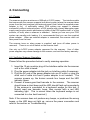
6. Operating the Scanner
The scanner can read barcodes in either omnidirectional or single-line
mode to accommodate different requirements. This scanner is truly
omnidirectional while single-line mode is usually used for better aiming on
the specific barcode on the same sheet of more than one barcode printed
closely.
6-1. Function Button
Press down the Function Button on top of the scanner as shown below
to switch between omnidirectional scanning and single-line scanning
modes.
Function Button
¾
If the scanner is powered off and re-turned on, even the
function button is pushed down before it’s turned off, the
scanner stays as factory default (omnidirectional scanning).
Hence, in order to have single-line scanning, the function
button has to be pressed up and pressed down again.
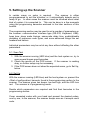
1) Presentation Mode:
As if the scanner is on the stand, the scanner will always stay active in
Presentation Mode. In other words, no matter if the Function Button LED
light is on or off, the scanner stays in the Presentation Mode.
9
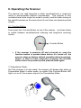
2) Multi-Line Scan Mode:
As if the scanner is not on the stand as well as the Function Button is not
pushed down (which Function Button LED is off), the scanner is in
Multi-Line Scan Mode by pressing the trigger button to decode.
The below illustrates the operation on large bulky items without aiming on
the barcodes.
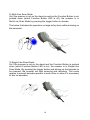
3) Single-Line Scan Mode:
As if the scanner is not on the stand and the Function Button is pushed
down (which Function Button LED is on), the scanner is in Single-Line
Scan Mode. By pressing the trigger button and aiming on the barcode to
be scanned, the scanner will start scanning and decoding. This mode
applies to several barcodes parallel to each other or when it is necessary
to aim on barcodes.
10
6-2. LED Indications
A dual color red-blue LED indicates operating status as follows:
LED status
Indication
Off
No power supplied to the scanner
Steady blue light
The scanner is on and ready to scan
One red flash
A barcode has been successfully decoded.
Steady red light
A barcode has been successfully decoded, but
the object is not removed from the scan window.
The scanner is in programming mode.
Flashing blue light
The scanner is in sleep mode.
Steady Purple light
This indicates the scanner has a motor or laser
failure. For motor failure, a periodic beep is
sounded. Return the unit for repair.
Alternate flashing red
and blue light
The scanner detects failing power.
check the power supply.
Please
6-3. Beeps
A beeper gives audible feedback on scanner operation.
Beeps
Indication
One beep
A barcode has been successfully decoded.
Four beeps in series
This indicates the scanner passed the power on
self-test and is operating properly.
Two beeps: low-high
The scanner has entered programming mode.
Two beeps: same tone
Scanner has returned from programming to
normal mode.
Continuous tone
This is a failure indication. Return the unit for
repair.
11
6-4. Sleep Mode
After the scanner has been inactive for a period of time, the laser
automatically turns off; then the motor will turn off and the scanner will
enter into “Sleep Mode”, the blue status LED blinks once as indication. To
wake up the scanner, simply present an object close to the exit window, or
press the trigger button.
Note: The scanner includes a motion sensor that detects activity in front
of the scan window. The detecting distance is up to about 15cm (6
inches) from the scan window,
12
7. Maintaining the Scanner
The scanner is designed for long-term trouble-free operation and rarely
requires any maintenance. Only an occasional cleaning of the scanner
window is necessary in order to remove dirt and fingerprints.
7-1. Cleaning the Scan Window
Wipe the scan window with a soft lint-free cloth and a non-abrasive
cleaner to avoid scratching and damaging the scan window. The scan
window may be cleaned while the scanner is running.
7-2. Replacing the Interface Cable
The standard interface cable is attached to the scanner with an 10-pin
modular connector. When the connector is properly seated, it is secured
in the scanner handle by a flexible retention tab. The cable is designed
to be field replaceable.
Replacement cables can be obtained from your authorized distributor.
To replace the cable, take the following steps.
1. Make sure that the power of your computer is switched off, and if a
power adapter is used, disconnect it from the scanner cable.
2. Disconnect the old scanner cable from the computer system.
3. Locate the small hole at the bottom of the scanner. (Shown as
indicated)
4. Use a metallic pin and insert into the hole.
5. Gently pull out the interface while pressing down the hole by pin.
The cable should come out.
6. Insert the new interface cable into the bottom of the scanner until it
clicks.
7. Plug the new cable into the host.
8. If a power adapter is used, plug the power adapter into the jack on
the interface cable.
13
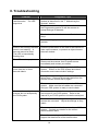
8. Troubleshooting
Problem
The scanner is on but cannot
read barcodes. The LED
stays blue.
Diagnostic Tips
The scanner window is dirty. Clean the scanner
window as described in the “7. Maintaining the
Scanner” section.
The presented barcode type is not enabled. Use
the Programming section to tell the scanner to
accept that type of barcode.
The host has disabled the scanner. Check host
setup.
The barcode type presented is not supported by the
scanner.
The scanner is on, but the
motor is not running; the facet
wheel is not rotating. A
barcode cannot be read.
The LED is intermittently
flashing blue.
The scanner has entered into the sleep mode.
Press the push button on the front of the scanner to
wake up the scanner, or present an object close to
the scan window.
The LED remains purple
Possible failure of the scanning safeguard circuit.
Disconnect the scanner from its power source
immediately and contact your dealer.
The scanner does not accept
more than two or three
barcode labels.
There is no proper handshaking with the POS
system. Switch on the POS system and check
connection and communication settings.
A stray barcode is sitting somewhere in the scanner
field of view. Remove all barcode labels from the
scanner’s scan volume and try again.
The scanner cannot send the data to the POS
system. Make sure that all cables are connected
and your POS system is ready to receive data.
A barcode is read by the
scanner but not accepted by
the POS system.
The communication cable is not connected to the
correct port of your POS system. Refer to the
manual of your POS system to locate the serial port.
The communication settings of the system and
scanner do not match. Adjust the settings so they
match.
The communication cable does not suit your POS
system. Contact your dealer for the correct
communication cable.
The software running on the POS system does not
support the data format of the barcode label.
14
9. Programming Guide
Scanning a series of programming bar code labels can configure the scanner.
This allows decoding options and interface protocols to be tailored to a specific
application. The configuration is stored in non-volatile memory and will not be lost
by removing power from the scanner.
The scanner must be properly powered before programming. For RS-232C type
scanners, an external power adapter must be used to supply DC power to the
scanner. If a keyboard emulation type scanner is used with an IBM PC/ AT, PS/2
or any fully compatible computers, power will be drawn from the keyboard port.
No external power adapter is required. If keyboard emulation type scanner is
used with any other non IBM PC compatible computers, an external power
adapter may be needed.
During the programming mode, the laser scanner will acknowledge a good and
valid reading with a short beep. It will give long beeps for either an invalid or bad
reading.
9-1. Programming Options
Programmable options are divided into four groups. The first group includes the
options that show the general behavior of the laser scanner. The second group
governs the operation of RS-232C type serial ports. The third group selects the
keyboard type that the keyboard emulation type will be emulated. The last group
sets the decoding parameters for each barcode symbology.
9-2. Default Parameters
This table gives the default settings of all the programmable parameters. The
default settings will be restored whenever the "Reset" programming label is
scanned and the laser scanner is in programming mode.
15
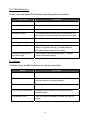
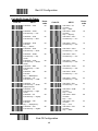
9-3. Factory Default Setting
Scanner Timing
Same code delay
RS-232 communication
Baud rate
Parity
Data Bits
Stop Bit
RTS/CTS
Terminator
Keyboard Wedge Communication
Terminal Type
Keyboard
Terminator
USB Communication
Terminator type
Code mode
Keyboard
Wand Emulation
Wand emulation speed
Data output
Decoder Selection
EAN/UPC
CODE 39
Code 32
CODABAR
ITF 2 OF 5
MSI
Chinese Post code
Code 93
Code 128
EAN-128
Beeper sound
Frequency
Duration
Led/Beep Before transmission
Operating parameter
Trigger mode(handheld mode)
Stand mode
Header and Trailer
Inter-Message delay
Inter character delay
Code Identifiers
Identifier code as ZEBEX standard
Identifier code as AIM standard
Code 39 identifier code
ITF 2 of 5 identifier code
Chinese post code identifier code
UPC-A identifier code
UPC-E identifier code
EAN-13 identifier code
EAN-8 identifier code
Codabar identifier code
Code 128 identifier code
Code 93 identifier code
MSI identifier code
Default
500msec
Default
9600
none
8
1
off
<CR><LF>
Default
PC/AT
US keyboard
Enter(Alpha numeric)
Default
Enter
Scan code
US keyboard
Default
Normal
Black=high
Default
Enable
Enable
Disable
Disable
Enable
Disable
Disable
Enable
Enable
Disable
Default
Medium
100msec
On
Default
Enable
Enable
None
None
None
Default
Disable
Disable
M
I
H
A
E
F
FF
N
K
L
P
16
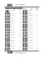
9-4. Default data transmit format
Code
EAN-13
EAN-8
UPCA
UPCE
CODE128
EAN128
CODE39
CODABAR
INTERLEAVED 2/5
CHINESE POST CODE
CODE93
MSI
Message format
D1 D2 D3 D4 D5 D6 D7 D8 D9 D10 D11 D12 D13
D1 D2 D3 D4 D5 D6 D7 D8
D1 D2 D3 D4 D5 D6 D7 D8 D9 D10 D11 D12
D1 D2 D3 D4 D5 D6 D7 D8
D1-Dx
(default 3~62)
]C1 D1-Dx (default 3~62)
D1-Dx
(default 3~62)
D1-Dx
(default 6~32)
D1-Dx
(default 6~32)
D1-Dx
(default 8~32)
D1-Dx
(default 3~32)
D1-Dx
(default 6~32)
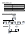
9-5. Program Procedure Using Barcode Manual
START
Read Start of
Configuration
Label
Set All
Defaults
Set Operating
Parameters
Set Serial Port
Parameters
Set Keyboard
Type
Finish
Discard
Read End of
Configuration
Label
Read Abort
Label
END
17
Set Decoding
Parameters
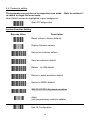
9-6. Parameter setting
The parameter can only be set in single-line scan mode. Refer to section 6-1
to switch to single line scan mode.
Note: Default values are highlighted in grey background.
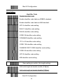
Start Of Configuration
System Function Setting
Barcode Value
Description
Reset (return to factory default)
Display firmware version
Return as customer default
Save as customer default
Return to USB default
Return to wand emulation default
Return to RS232 default
IBM PC/AT/PS/2 Keyboard emulation
Abort
(exit programming mode(no update)
End Of Configuration
18
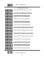
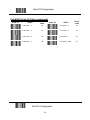
Start Of Configuration
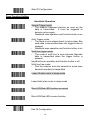
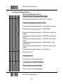
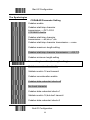
Scan Function Setting
Handheld Operation
Normal Trigger mode
y
The scanner becomes inactive as soon as the
data is transmitted. It must be triggered to
become active again.
Handheld scan operation and function button is on
Auto Trigger mode
The mode is auto object detect to active laser. Bar
code data is transmitted when the trigger button is
pressed
y
Handheld scan operation and function button is on
y
Multi line trigger mode.
y
The mode is multi line to scan barcode. Barcode
data is transmitted when the trigger button is
pressed
Handheld scan operation and function button is off
Multi line free mode.
Pick the scanner and aim barcode to quick scan
barcode and data is transmitted
y
Laser off when enter to sleep mode
Laser flash when enter to sleep mode
Blue LED/Red LED function as normal
Blue LED/Red LED reverse function
End Of Configuration
19
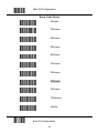
Start Of Configuration
Same Code Delay
50msec
200msec
400msec
600msec
800msec
100msec
300msec
500msec
700msec
1000msec
Infinite
End Of Configuration
20
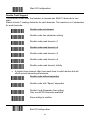
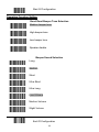
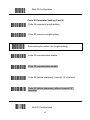
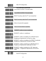
Start Of Configuration
Double Field Support
The scanner allows user the freedom to decode two EAN-13 barcode to one
scan.
Select at least 1 leading character for each barcode .The maximum is 4 characters
for each barcode.
Double code not allowed
Double code free character setting
Double code seek timeout x 1
Double code seek timeout x 2
Double code seek timeout x 3
Double code seek timeout x 4
Double code seek timeout :Infinity
¾
A higher times timeout offer more seek time to catch double but will
effect normal barcode performance.
Double code without separator
Double code with “Space” separator
Double Code Separator free setting
Only one ACSII character available
Save setting to confirm
End Of Configuration
21
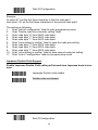
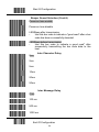
Start Of Configuration
Example
To select 471 as the first three character in the first code pair1
And select 121 as the first three characters in the second code pair2.
The setting as following:
1.
Scan “start of configuration” label to enter programming mode
2.
Scan “Double code free character setting” label
3.
Scan code byte “4” from ASCII code table
4.
Scan code byte “7” from ASCII code table
5.
Scan code byte “1” from ASCII code table
6.
Scan “save setting to confirm” label to save first code pair setting
7.
Scan code byte “1” from ASCII code table
8.
Scan code byte “2” from ASCII code table
9.
Scan code byte “1” from ASCII code table
10. Scan “save setting to confirm” label to save second code pair setting
11. Scan ”end of “configuration” label exit programming mode
Japanese Double Field Support
Enable Japanese Double Field setting will decode two Japanese book at one
scan.
Japanese Double code enable
Double code not allowed
End Of Configuration
22
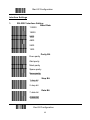
Start Of Configuration
Operation Function Setting
Good Read Beeper Tone Selection
Medium beeper tone
High beeper tone
Low beeper tone
Speaker disable
Beeper Sound Selection
Long
Medium
Short
Ultra Short
Ultra Long
Loud Volume
Medium Volume
Slight Volume
End Of Configuration
23
Start Of Configuration
Beeper Sound Selection (Cont’d)
Power-on tone enable
Power-on tone disable
LED/Beep after transmission.
Use this bar code to indicate a "good read" after a bar
code has been successfully decoded.
y
LED/Beep before transmission
y
Use this bar code to indicate a good read" after
successfully transmitting the bar code data to the
host.
Inter Character Delay
0ms
2ms
5ms
10ms
20ms
50ms
Inter Message Delay
0 ms
100 ms
500 ms
1000 ms
End Of Configuration
24
Start Of Configuration
Interface Settings
1.
RS-232C Interface Setting
Baud Rate
115200
19200
9600
4800
2400
1200
Parity Bit
Even parity
Odd parity
Mark parity
Space parity
None parity
Stop Bit
1 stop bit
2 stop bit
Data Bit
7 data bit
8 data bit
End Of Configuration
25
Start Of Configuration
Handshaking Protocol
None handshaking
ACK/NAK
Xon/Xoff
RTS/CTS
Enable BEEPER ON<BEL> CHARACTER
Ignore Beep on<BEL> character
Disable ACK/NAK timeout beeper
Enable ACK/NAK timeout beeper(three sound
beeper sound)
ACK/NAK response time 300ms
ACK/NAK response time 2s
ACK/NAK response time 500ms
ACK/NAK response time 3s
ACK/NAK response time 1s
ACK/NAK response time 5s
ACK/NAK response time infinity
End Of Configuration
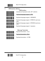
26
Start Of Configuration
Message Terminator
RS-232 message terminator—none
RS-232 message terminator—CR/LF
RS-232 message terminator—C
RS-232 message terminator—LF
RS-232 message terminator—H tab
RS-232 message terminator—STX/ETX
RS-232 message terminator—EOT
End Of Configuration
27
Start Of Configuration
2.
Keyboard Wedge Setting
Keyboard Wedge Setting
IBM PC/AT/PS/2 Keyboard emulation
International Keyboard mode.( ALT method).
Keyboard language support---USA
Keyboard language support---UK send scan code
Keyboard language support---GERMANY
Keyboard language support---FRENCH send scan
code
Keyboard language support---SPANISH send scan
code
Keyboard language support---ITALIAN send scan
code
Keyboard language support---Switzerland send
scan code
Keyboard language support---Belgium send scan
code
Keyboard language support---Japanese
Capital lock on
Capital lock off
Function key emulation enable
Function key emulation disable
Send number as normal data
Send number as keypad data
End Of Configuration
28
Start Of Configuration
Message Terminator
Keyboard terminator---none
Keyboard terminator---Enter
Keyboard terminator---H-TAB
End Of Configuration
29
Start Of Configuration
3.
USB Interface Setting
USB interface
International Keyboard mode.( ALT method).
Keyboard language support---USA
Keyboard language support---GERMANY
Keyboard language support---FRENCH send scan
code
Keyboard language support---SPANISH send scan
code
Keyboard language support---Japanese
Message Terminator
Keyboard terminator---none
Keyboard terminator---Enter
Keyboard terminator---H-TAB
End Of Configuration
30
Start Of Configuration
4.
Wand Emulation Setting
Wand emulation is not supported as standard, if needed, please contact
your distributor.
Wand Emulation
All barcode will be decoded and transmitted in that
symbology
Enable Wand output data format as CODE39
Wand emulation data output black=high
y
Scan this bar code to set quiet zones and
spaces low and bars =high.
Wand emulation data output black=low
Scan this bar code to set quiet zones and
spaces high and bars=low
y
Idle = high
y
Idle state refers to the TTL logic level of the
Wand Emulation signal when not in use
Idle = low
Idle state refers to the TTL logic level of the
Wand Emulation signal when not in use
y
End Of Configuration
31
Start Of Configuration
Wand Emulation (Cont’d)
Wand emulation speed-----Low
y
This option allows the transmission of wand
emulation at 1ms narrow element width
Wand emulation speed-----medium
This option allows the transmission of wand
emulation at 600us narrow element width
y
Wand emulation speed-----normal
Wand emulation speed-----high
This option allows the transmission of wand
emulation at 300us narrow element width
y
Wand emulation speed-----higher
This option allows the transmission of wand
emulation at 100 us narrow element width
y
Wand emulation narrow/wide ratio 1:2
Wand emulation narrow/wide ratio 1:3
End Of Configuration
32
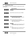
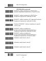
Start Of Configuration
The Symbologies
CODABAR Parameter Setting
Codabar enable
Codabar start/stop character
transmission-----DC1~DC4
CODABAR disable
Codabar start/stop character
transmission-----a/t,b/n,c/*,d/e
Codabar start/stop character transmission-----none
Codabar maximum length setting
Codabar start/stop character transmission-----A,B,C,D
Codabar minimum length setting
Save setting to confirm (for length setting)
Codabar concatenation disable
Validate modulo 16 and transmit
Codabar concatenation enable
Codabar data redundant check=off
No check character
Codabar data redundant check=1
Validate modulo 16,but don’t transmit
Codabar data redundant check=2
End Of Configuration
33
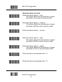
Start Of Configuration
Code 39 Parameter Setting
Code 39 enable
FULL ASCII code 39
Code 39 disable
Code 39 start/stop character transmission
Code 39 start/stop character without transmission
Code 32 enable
Code 32 disable
Code 39 check digit calculate and transmit
No check character
Code 39 check digit calculate but without transmit
Code 39 data redundant check=off
Code 39 data redundant check=1
Code 39 data redundant check=2
End Of Configuration
34
Start Of Configuration
Code 39 Parameter Setting (Cont’d)
Code 39 maximum length setting
Code 39 minimum length setting
Save setting to confirm (for length setting)
Code 39 concatenation enable
Code 39 concatenation disable
Code 32 (Italian pharmacy) transmit “A” character
Code 32 (Italian pharmacy) without transmit ”A”
character
End Of Configuration
35
Start Of Configuration
Code 93 Parameter Setting
Code 93 enable
Code 93 disable
Code 93 data redundant check=off
Code 93 data redundant check=1
Code 93 data redundant check=2
Code 93 maximum length setting
Code 93 minimum length setting
Save setting to confirm (for length setting)
Code 93 check digit calculate but without transmit
Code 93 check digit not calculate and without
transmit
Code 93 check digit calculate and transmit
End Of Configuration
36
Start Of Configuration
Code 128
Code 128 enable
Code 128 disable
EAN 128 enable
EAN 128 disable
Code128 FNC2 concatenation enable
Code128 FNC2 concatenation disable
Code 128 data redundant check=off
Code 128 data redundant check=1
Code 128 data redundant check=2
Code 128 maximum length setting
Code 128 minimum length setting
Save setting to confirm (for length setting)
End Of Configuration
37
Start Of Configuration
Chinese Post Code
Chinese post code enable
Chinese post code disable
Chinese post codedata redundant check=off
Chinese post code data redundant check=1
Chinese post codedata redundant check=2
Chinese post code maximum length setting
Chines post code code minimum length setting
Save setting to confirm (for length setting)
End Of Configuration
38
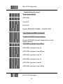
Start Of Configuration
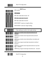
MSI/Plessy
MSI enable
MSI disable
MSI data redundant check= off
MSI data redundant check=1
MSI data redundant check=2
MSI/PLESSY maximum length setting
MSI/PLESSY minimum length setting
Save setting to confirm (for length setting)
MSI/Plessy double check digit calculate but not
transmit
MSI/Plessy double check digit calculate and both
transmit
MSI/Plessy double check digit without calculate and
transmit
MSI/Plessy single check digit calculate but without
transmit
MSI/Plessy double check digit calculate but only first
digit transmit
MSI/Plessy single check digit calculate and transmit
End Of Configuration
39
Start Of Configuration
ITF 2 of 5
ITF 2 of 5 enable
ITF 2 of 5 disable
IATA code enable
IATA disable
ITF 2 of 5 check digit calculate and transmit
ITF 2 of 5 check digit calculate but without transmit
ITF 2 of 5 no check character
ITF 2 of 5 one Fixed length setting
ITF 2 of 5 two Fixed length setting
ITF 25 data redundant check=off
ITF25 data redundant check=1
ITF25 data redundant check=2
ITF 2 of 5 code minimum length setting
ITF 2 of 5 length variable
ITF 2 of 5 code maximum length setting
Save setting to confirm (for length setting)
End Of Configuration
40
Start Of Configuration
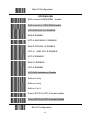
UPC/EAN/JAN
EAN convert toISSN/ISBN enable
EAN convert to ISSN.ISBN disable
UPC/EAN/JAN ALL ENABLE
EAN-8 ENABEL
UPC-A AND EAN-13 ENABLE
EAN-8 OR EAN-13 ENABLE
UPC-A AND UPC-E ENABLE
UPC-E ENABLE
EAN-13 ENABLE
UPC-A ENABEL
UPC/EAN Addendum Disable
Add on 5 only
Add on 2 only
Add on 2 or 5
Force UPC-E to UPC-A format enable
Force UPC-E to UPC-A format disable
End Of Configuration
41
Start Of Configuration
UPC/EAN/JAN (Cont’d)
Force UPC-A to EAN-13 format enable
Force UPC-A to EAN-13 format disable
Transmit UPC-A check digit enable
Transmit UPC-A check digit disable
Transmit UPC-E check digit enable
Transmit UPC-E check digit disable
Transmit UPC-E leading character enable
Transmit UPC-E leading character disable
Transmit UPC-A leading character enable
Transmit UPC-A leading character disable
Transmit EAN-13 check digit disable
Transmit EAN-13 check digit enable
Transmit EAN-8 check digit enable
Transmit EAN-8 check digit disable
End Of Configuration
42
Start Of Configuration
UPC/EAN/JAN (continued)
force EAN-8 to EAN-13 format enable
force EAN-8 to EAN-13 format disable
EAN-13 country code first “0” can transmitted
EAN-13 country code first:”0” can’t transmitted
Add-on format with separator
Add-on format without separator
EAN/UPC +add-on (none mandatory)
EAN/UPC +add-on ( mandatory)
EAN/UPC +add-on mandatory for 378/379 French
Supplement requirement, not sent for other
EAN/UPC +add-on mandatory for 978/977 (bookland)
Supplement requirement, not sent for other
EAN/UPC +addon mandatory for 434/439 German
Supplement requirement, optionally for other
EAN/UPC +addon mandatory for 491 Japanese
(bookland) Supplement requirement, not sent for
other
End Of Configuration
43
Start Of Configuration
UPC/EAN/JAN (continued)
EAN/UPC +addon mandatory for 419/414 Euro
amounts Supplement requirement, not sent for other
EAN/UPC +addon mandatory for 414/419 Euro
Supplement requirement, optionally for other
EAN/UPC +addon mandatory 491 Japanese (bookland)
Supplement requirement, optionally for other
Disable all EAN/OPC + Add-on mandatory for specific
country code
EAN/UPC +add-on mandatory for
414/419/378/379/978/977/434/439/529/ Euro
Supplement requirement, optionally for other
EAN/UPC +add-on mandatory for
414/419/378/379/978/977/434/439/529/ Euro
Supplement requirement, not sent for other
Addendum seek timeout value=1
Addendum seek timeout value=2
Addendum seek timeout value=3
End Of Configuration
44
Start Of Configuration
Addendum Seek Timeout
Note: A higher timeout value setting offer more assurance that an addendum has been read
correctly while a lower setting allows faster scanning performance.
Addendum seek timeout value=4
Addendum seek timeout value=5
Addendum seek timeout value=6
Addendum seek timeout value=7
Addendum seek timeout value=8
Addendum seek timeout value=9
Addendum seek timeout value=10
2 digit addendum data redundant check=off
2 digit addendum data redundant check=1
2 digit addendum data redundant check=2
2 digit addendum data redundant check=3
5 digit addendum data redundant check=off
5 digit addendum data redundant check=1
5 digit addendum data redundant check=2
5 digit addendum data redundant check=3
End Of Configuration
45
Start Of Configuration
Data Editing
Identifier Code
Disable identifier code
Enable identifier code table as ZEBEX standard
Enable identifier code table as AIM standard.
UPC-A identifier code setting
EAN-13 identifier code setting
EAN-8 identifier code setting
CODE 39 identifier code setting
CODABAR identifier code setting
ITF 2 of 5 identifier code setting
CODE 128 identifier code setting
CHINESE POST CODE identifier code setting
CODE 93 identifier code setting
UPC-E identifier code setting
MSI identifier code setting
Save setting to confirm (for length setting)
Add code length as header enable (2 Bytes)
Add code length as header disable (2 Bytes)
End Of Configuration
46
Start Of Configuration
Header And Trailer
Header (Preamble)
Trailer (Postamble)
Truncate header character
Truncate trailer character
End Of Configuration
47
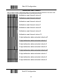
Start Of Configuration
Full ASCII Code 39 Table
Code 39
Hexacode
ASCII
Full ASCII ---NUL
00
Full ASCII ---SOH
Function key-----“Ins”
01
Full ASCII ---STX
Function key-----“Del”
02
Full ASCII ---ETX
Function
key-----“Home”
Full ASCII ---EOT
Function key-----“End”
Code 39
ASCII
Hexacode
Full ASCII ---SI
Function
key-----“Shift”
Full ASCII ---DLE
Function
key-----“5(num)”
Full ASCII ---DC1
Function key-----“F1”
0F
03
Full ASCII ---DC2
Function key-----“F2”
12
04
Full ASCII ---DC3
Function key-----“F3”
13
Full ASCII ---ENQ
Function key-----“Up
arrow”
Full ASCII ---ACK
Function key-----“Down
arrow”
Full ASCII ---BEL
Function key-----“Left
arrow”
Full ASCII ---BS
Function
key-----“Backspace”
Full ASCII ---HT
Function key-----“TAB”
05
Full ASCII ---DC4
Function key-----“F4”
14
06
Full ASCII ---NAK
Function key-----“F5”
15
07
Full ASCII ---SYN
Function key-----“F6”
16
08
Full ASCII ---ETB
Function key-----“F7”
17
09
Full ASCII ---CAN
Function key-----“F8”
18
Full ASCII ---LF
Function key-----“Enter
(alpha numeric”
Full ASCII ---VT
Function key-----“right
arrow”
Full ASCII ---FF
Function key-----“PgUp”
0A
Full ASCII ---EN
Function key-----“F9”
19
0B
Full ASCII ---SUB
Function
key-----“F10”
Full ASCII ---ESC
Function
key-----“F11”
Full ASCII ---FS
Function
key-----“F12”
Full ASCII ---GS
Function
key-----“ESC”
1A
Full ASCII ---CR
Function
key-----“Enetr(num.)”
Full ASCII ---SO
Function key-----“PgDn”
0C
0D
0E
End Of Configuration
48
10
11
1B
1C
1D
Start Of Configuration
Full ASCII Code 39 Table (continued)
Code 39
ASCII
Hexacode
Code 39
ASCII
Hexacode
Full ASCII ---RS
Function
key-----“CTL(L)”
1E
Full ASCII ----
2D
Full ASCII ---US
Function
key-----“ALT(L)”
1F
Full ASCII ---.
2E
Full ASCII ---SP
20
Full ASCII ---/
2F
Full ASCII ---!
21
Full ASCII ---0
30
Full ASCII ---“
22
Full ASCII ---1
31
Full ASCII ---#
23
Full ASCII ---2
32
Full ASCII ---$
24
Full ASCII ---3
33
Full ASCII ---%
25
Full ASCII ---4
34
Full ASCII ---&
26
Full ASCII ---5
35
Full ASCII ---‘
27
Full ASCII ---6
36
Full ASCII --- (
28
Full ASCII ---7
37
Full ASCII ---)
29
Full ASCII ---8
38
Full ASCII ---*
2A
Full ASCII ---9
39
Full ASCII ---+
2B
Full ASCII ---:
3A
Full ASCII ---,
2C
Full ASCII ---;
3B
End Of Configuration
49
Start Of Configuration
Full ASCII Code 39 Table (continued)
Code 39
Hexacode
ASCII
Code 39
ASCII
Hexacode
Full ASCII ---<
3C
Full ASCII ---K
4B
Full ASCII ---=
3D
Full ASCII ---L
4C
Full ASCII --->
3E
Full ASCII ---M
4D
Full ASCII ---?
3F
Full ASCII ---N
4E
Full ASCII ---@
40
Full ASCII ---O
4F
Full ASCII ---A
41
Full ASCII ---P
50
Full ASCII ---B
42
Full ASCII ---Q
51
Full ASCII ---C
43
Full ASCII ---R
52
Full ASCII ---D
44
Full ASCII ---S
53
Full ASCII ---E
45
Full ASCII ---T
54
Full ASCII ---F
46
Full ASCII ---U
55
Full ASCII ---G
47
Full ASCII ---V
56
Full ASCII ---H
48
Full ASCII ---W
57
Full ASCII ---I
49
Full ASCII ---X
58
Full ASCII ---J
4A
Full ASCII ---Y
59
End Of Configuration
50
Start Of Configuration
Full ASCII Code 39 Table (continued)
Code 39
ASCII
Hexacode
Code 39
ASCII
Hexacode
Full ASCII ---Z
5A
Full ASCII ---i
69
Full ASCII ---[
5B
Full ASCII ---j
6A
Full ASCII ---\
5C
Full ASCII ---k
6B
Full ASCII ---]
5D
Full ASCII ---l
6C
Full ASCII ---^
5E
Full ASCII ---m
6D
Full ASCII ---_
5F
Full ASCII ---n
6E
Full ASCII ---`
60
Full ASCII ---o
6F
Full ASCII ---a
61
Full ASCII ---p
70
Full ASCII ---b
62
Full ASCII ---q
71
Full ASCII ---c
63
Full ASCII ---r
72
Full ASCII ---d
64
Full ASCII ---s
73
Full ASCII ---e
65
Full ASCII ---t
74
Full ASCII ---f
66
Full ASCII ---u
75
Full ASCII ---g
67
Full ASCII ---v
76
Full ASCII ---h
68
Full ASCII ---w
77
End Of Configuration
51
Start Of Configuration
Full ASCII Code 39 Table (continued)
Code 39
ASCII
Hexacode
Code 39
ASCII
Hexacode
Full ASCII ---x
78
Full ASCII ---|
7C
Full ASCII ---y
79
Full ASCII ---}
7D
Full ASCII ---z
7A
Full ASCII ---~
7E
Full ASCII ---{
7B
Full ASCII ---DEL
7F
End Of Configuration
52