1
1
Advanced Handheld High-Speed Laser Scanner
Revision History
Changes to the original manual are listed below:
Version
Date
Description of Version
1.0
June. 25, 2010 Initial release
i
Handheld Bluetooth® CCD/Laser Scanner
Important Notice
No warranty of any kind is made in regard to this material, including, but not limited to,
implied warranties of merchantability or fitness for any particular purpose. We are not
liable for any errors contained herein nor for incidental or consequential damages in
connection with furnishing, performance or use of this material. We shall be under no
liability in respect of any defect arising from fair wear and tear, willful damage,
negligence, abnormal working conditions, failure to follow the instructions and warnings,
or misuse or alteration or repair of the products without written approval. No part of this
document may be reproduced, transmitted, stored in a retrieval system, transcribed, or
translated into any human or computer or other language in any form or by any means
electronic, mechanical, magnetic, optical, chemical, biological, manual or otherwise,
except for brief passages which may be quoted for purposes of scholastic or literary
review, without express written consent and authorization. We reserve the right to make
changes in product design without reservation and without notification. The material in
this guide is for information only and is subject to change without notice. All trademarks
mentioned herein, registered or otherwise, are the properties of their various, ill,
assorted owners.
General Handling Precautions
Do not dispose the scanner in fire.
Do not put the scanner directly in the sun or by any heat source.
Do not use or store the scanner in a very humid place.
Do not drop the scanner or allow it to collide violently with other objects.
Do not take the scanner apart without authorization
Guidance for Printing
This manual is in A5 size. Please double check your printer setting before printing it out.
When the barcodes are to be printed out for programming, the use of a high-resolution
laser printer is strongly suggested for the best scan result.
Copyright © 2010. All rights reserved.
Handheld Bluetooth® CCD/Laser Scanner
ii
Radio Notice
This equipment generates uses and can radiate radio frequency energy. If not installed
and used in accordance with the instructions in this manual, it may cause interference to
radio communications. The equipment has been tested and found to comply with the
limits for a Class A computing device pursuant to EN55022 and 47 CFR, Part 2 and Part 15
of the FCC rules. These specifications are designed to provide reasonable protection
against interference when operated in a commercial environment.
Radio and Television Interference
Operation of this equipment in a residential area can cause interference to radio or
television reception. This can be determined by turning the equipment off and on.
The user is encouraged to try to correct the interference by one or more of the following
measures:
- Reorient the receiving antenna.
- Relocate the device with respect to the receiver.
- Move the device away from the receiver.
- Plug the device into a different outlet so that the device and the receiver are on
different branch circuits.
If necessary the user may consult the manufacturer, and authorized dealer, or
experienced radio/television technician for additional suggestions. The user may find
the following booklet prepared by the Federal Communications Commission helpful:
“How to Identify and Resolve Radio-TV Interference Problems.” This booklet is available
from the U.S. Government Printing Office, Washington, DC 20402 U.S.A., Stock No.
004000003454.
Laser Safety
This equipment generates, uses, and can radiate radio frequency energy. If not installed
and used in accordance with the instructions in this manual, it may cause interference to
radio communications. The equipment has been tested and found to comply with the
limits for a Class A computing device pursuant to EN55022 and 47 CFR, Part 2 and Part 15
of FCC Rules. These specifications are designed to provide reasonable protection against
interference when operated in a commercial environment.
Radiant Energy: The laser scanner uses one low-power visible laser diodes operating at
650nm in an opto-mechanical scanner resulting in less than 3.9μW radiated power as
observed through a 7mm aperture and averaged over 10 seconds.
Do not attempt to remove the protective housing of the scanner, as unscanned laser light
with a peak output up to 0.8mW would be accessible inside.
iii
Handheld Bluetooth® CCD/Laser Scanner
Laser Light Viewing: The scan window is the only aperture through which laser light may
be observed from this product. A failure of the scanner engine, while the laser diode
continues to emit a laser beam, may cause emission levels to exceed those for safe
operation. The scanner has safeguards to prevent this occurrence. If, however, a
stationary laser beam is emitted, the failing scanner should be disconnected from its
power source immediately.
Adjustments: Do not attempt any adjustments or alteration of this product. Do not
remove the protective housing of the scanner. There are no user-serviceable parts inside.
Optical: The use of optical instruments with this product will increase the eye hazard.
Optical instruments include binoculars, magnifying glasses, and microscopes but do not
include normal eye glasses worn by the user.
CAUTION: Use of controls or adjustments or performance of procedures other than those
specified herein may result in hazardous radiation exposure.
For CE-Countries
This scanner is in conformity with CE standards. Please note that an approved, CE-marked
power supply unit should be used in order to maintain CE conformance.
Handheld Bluetooth® CCD/Laser Scanner
iv
Table of Contents
Important Notice..................................................................................................................ii
General Information.............................................................................................................1
Introduction .................................................................................................................1
Unpacking ....................................................................................................................2
Scanner Outline............................................................................................................3
Cradle Outline ..............................................................................................................3
Getting Started.....................................................................................................................4
Installing and Charging Scanner Batteries....................................................................4
Installing Batteries................................................................................................4
Charging Batteries ................................................................................................5
Connecting the Cradle..................................................................................................6
Connection on Cradle Host ..................................................................................7
Attach the Interface Cable....................................................................................7
Detach the Interface Cable...................................................................................9
Pairing Scanner and Cradle Host ........................................................................................10
Cradle Host.................................................................................................................10
SPP - Slave ..................................................................................................................11
SPP - Master ...............................................................................................................15
Paging the Scanner.............................................................................................................17
Scanning.....................................................................................................................17
Handheld Scanning ............................................................................................17
Hands-free Scanning ..........................................................................................17
Data Transmit Method .......................................................................................................18
Normal (default).........................................................................................................18
Out-of-Range Mode ...................................................................................................18
Standard Batch Mode ................................................................................................18
Cradle Contact Batch Mode .......................................................................................19
ACK/NAK protocol or Frame packing .................................................................................20
Scanner to remote application...................................................................................21
Beeper Indication...............................................................................................................22
LED Indication ....................................................................................................................23
The Scanner................................................................................................................23
The Communication Cradle........................................................................................24
Maintenance ......................................................................................................................25
Cleaning the Window and Housing............................................................................25
Inspecting on Interface Cables ...................................................................................25
Battery........................................................................................................................25
Programming Guide ...........................................................................................................26
Default Parameters ....................................................................................................26
Program Procedure Using Barcode Manual ...............................................................29
Parameter Setting ......................................................................................................30
v
Handheld Bluetooth® CCD/Laser Scanner
USER’S MANUAL
General Information
Introduction
This scanner has two types scan engines, CCD and Laser, to choose from and they are well
featured with advanced wireless technology, enabling working efficiency for
simultaneous data transfer when scanning as well as working portability as not being
constrained by short of cable length. Working places as shipping industry, cargo
warehouses, superstores, pharmacies, and many more open-space or large-scale
manufacturing sites are delighted to enjoy this move-around freedom.
The cradle, a dongle or any device with wireless technology can be the host of this
scanner. All scanned data are instantly transferred to the connected host in a 100-meter
connection range in open space or 75-meter range in indoor environments (the actual
communication range may vary due to different indoor placement). As if out of
connection range, the embedded 32KB flash memory provides sufficient data space to
store up to 500 sets of data.
Either scanning in the handheld or hands-free mode, this scanner always offers a highaccuracy and reliable scanning ability. This scanner would be your trusted tool scanning
partner.
1
Handheld Bluetooth® CCD/Laser Scanner
USER’S MANUAL
Unpacking
This scanner package contains:
1 ea.
Wireless Single-Line CCD or Laser Scanner
1 ea.
1 ea.
Charging Cradle or Cradle with Radio
Communication
DC 9V Power Adapter
2 ea.
Ni-MH AA Recharge Battery
1 ea.
Interface Cable (only for the cradle host)
1 ea.
Hand stripe
1 ea.
User’s Manual CD
If any contents are damaged or missing, please contact your dealer immediately.
Please leave this user’s manual within easy access of person using the scanner.
Handheld Bluetooth® CCD/Laser Scanner
2
USER’S MANUAL
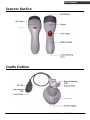
Scanner Outline
Cradle Outline
3
Handheld Bluetooth® CCD/Laser Scanner
USER’S MANUAL
Getting Started
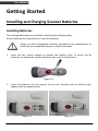
Installing and Charging Scanner Batteries
Installing Batteries
The rechargeable batteries are packed individually for shipping safety.
Please follow up the steps below to install the batteries.
Always use the rechargeable batteries provided by the manufacturer to
avoid any non-compatible danger or void the warranty.
1.
Loose the two screws enough to remove the battery cover. (It would not be
necessary to remove the screws otherwise may result in losing them.)
Figure 2-1
2.
Insert the batteries into the scanner one by one. (positive pole to positive pole,
negative pole to negative pole)
Figure 2-2
Handheld Bluetooth® CCD/Laser Scanner
Figure 2-3
4
USER’S MANUAL
3.
Put back the battery cover, and tighten both screws.
Figure 2-4
Charging Batteries
For users with the charging cradle, you can connect the charging cradle with power
adapter and the scanner is now in charging.
For cradle host users, you can connect the cradle with the power adapter (shown as
Figure 2-9 as example) first, then place the scanner into the cradle in a 30° angle (shown
as Figure 2-5) and press down to make it seat tight into the cradle (shown as Figure 2-6);
a clear and short beep is heard when position correctly into the cradle.
Press Down
Figure 2-5
5
Figure 2-6
Handheld Bluetooth® CCD/Laser Scanner
USER’S MANUAL
Once the scanner is well situated in the cradle, press down any one of the small buttons
at the side of cradle LED lamp to start charging (Shown as Figure).
Figure 2-7
Press any one to start charging
The LED of scanner light in RED as in charge, and light in BLUE when full charged. Refer to
Chapter 9 for LED indication.
We call this “Smart Charge”, as battery life is well depended on the charging number of
times, so only charge the batteries when necessary by following the abovementioned
procedures to prolong your battery life.
You may also set up auto-charging as every time the scanner is placed into the cradle.
Follow and scan the appropriate barcode symbols to set up from programming section of
this booklet
Note:
For first charging, always charge the batteries over 5 hours continuously to
prolong your battery life.
After every full charge, you may use the scanner for 8 hours continuously.
Recommended charging environment is temperature in 0°C~35°C (32°F~95°F).
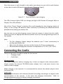
Connecting the Cradle
There are two types of cradle to select for this scanner.
Charging Cradle
Cradle Host
Charging Cradle
This cradle designs for battery charging only, it does not support radio communication.
Simply connect the external DC-9V9W power adapter into it and place scanner into
cradle to start charging.
When charging is not required, it is recommended to remove the adapter plug to retain
the battery life.
Cradle Host
The cradle host features with advanced wireless technology and designs to support radio
communication to the scanner. It the same has charging functionality. Refer to
Charging Batteries section for battery charging instructions.
Handheld Bluetooth® CCD/Laser Scanner
6
USER’S MANUAL
Connection on Cradle Host
The scanner pairs with the cradle, when the scanner scans barcode data and passes to
cradle via radio communication, the cradle sends data to host by its interface cable.
Steps to connect the cradle to host as follows:
1.
Take the desirable interface cable and insert the RJ-45 connector to cradle cable
box until you hear a clear and short “click” sound, then connect the other end to
the host.
2.
When using Keyboard wedge and USB interface for radio communication, it is not
necessary to have an external power adapter if host has sufficient power. But
these interfaces need external power adapter when charging batteries.
Note: When external power adapter (9V) is available, the cradle will disregard
the power supply from host (5V).
3.
If using RS-232 interface, it is necessary to plug an external power adapter always.
Plug the power adapter into the DC-Jack of cradle cable box. (Shown as Figure 2-10)
4.
Once cradle powers up, its LED lamp lights RED for one second then turns to flashes
BLUE light. The BLUE LED means the cradle is waiting to be connected. If the
scanner pairs with this cradle, they are connected, and BLUE LED light is always on.
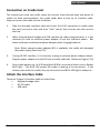
Attach the Interface Cable
There are 3 types of interface cable to select from,
Keyboard wedge cable
RS-232 cable
USB cable
7
Handheld Bluetooth® CCD/Laser Scanner
USER’S MANUAL
Keyboard wedge cable
Figure2-8
Communication Only
Figure2-9 Communication and Charging
RS-232 Cable
Always require adapter for both communication and charging
Figure 2-10
Handheld Bluetooth® CCD/Laser Scanner
8
USER’S MANUAL
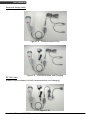
USB Cable
Figure 2-11 Communication Only
Figure 2-12 Communication and Charging
Detach the Interface Cable
There is a hole on cradle cable box, and use a sharp pin to push down the hole while
using another hand gently pull out the interface cable to release it slowly. (Shown in
Figure 2-13)
9
Figure 2-13
Handheld Bluetooth® CCD/Laser Scanner
USER’S MANUAL
Pairing Scanner and Cradle Host
This scanner supports three radio communication types,
Cradle Host,
SPP (Serial Protocol Profile) Slave
SPP (Serial Protocol Profile) Master.
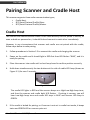
Cradle Host
The scanner and communication cradle in the same delivery box are paired in factory, as
soon as both are powered on, it should find and connect to each other immediately.
However, in any circumstance that scanner and cradle are not paired with the cradle,
follow steps below to redo pairing.
1.
Follow procedures in Section 2.2 to connect the cradle and charging the scanner.
2.
Power on the cradle and it should light in RED first than LED flashes “BLUE”, and it is
ready for pairing.
3.
Place the scanner into cradle until a short beep heard to confirm position correctly.
4.
Hold down simultaneously the two buttons at the side of cradle LED lamp (shown as
Figure 3-1) for over 2 seconds.
Figure 3-1
The cradle LED lights in RED and the scanner beeps as a High-Low-High beep tone,
and then the scanner and cradle both LED flashes. If pairing is success, you will
hear Low-High beep tone and cradle LED stays in BLUE and scanner LED stays in
GREEN.
5.
If the cradle is locked for pairing, or if scanner is not set in cradle host mode, it beeps
twice and GREEN LED on scanner puts out.
Handheld Bluetooth® CCD/Laser Scanner
10
USER’S MANUAL
Note:
In cradle host mode, the scanner is always in master mode and cradle is in slave
mode. Therefore, you have to scan on “Unlock Pairing Mode” barcode symbol to
unlock paired scanner and cradle, than connect or link to other devices.
6.
As the scanner links to the communication cradle, the cradle LED stays in BLUE. If
in any case the scanner link timeout or enters power down mode, then the cradle
LED flashes in BLUE. Press scanner trigger or place the scanner back into the cradle,
the communication links automatically again.
Note:
The default radio communication type of scanner sets in cradle host, if by any chance the
scanner lost this setting, use the programming barcode symbologies provided in this
booklet to set it as “Cradle Host” again.
SPP - Slave
In the mode of SPP Slave, the scanner is remote by connecting with Serial Protocol Profile
(SPP) host. Therefore, please first make sure your host device is well equipped with
advanced wireless technology connectivity and an application software before following
the steps below to start pairing.
Note:
All host device and application software has different operating features, here we take a
Widcomm BTW utility as an example.
1.
Turn on the host computer and activate its Bluetooth® connection.
2.
Scan “Start of Configuration” to enter programming mode
3.
Scan “SPP Slave” barcode label
4.
Scan “End of Configuration” barcode label to exit programming mode. Now, the
scanner LED flashes in GREEN, indicating it’s waiting to be connected.
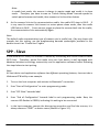
5.
In the host computer, execute the discovering procedure and find the scanner, it is
always shown as “ZBBT” as device name (Shown in Figure 3-2).
11
Handheld Bluetooth® CCD/Laser Scanner
USER’S MANUAL
Figure 3-2
6.
Select “ZBBT” the scanner, as the scanner default encryption is enabled, and you will
be requested to enter the PIN code as “12345678” to start pairing.
Figure 3-3
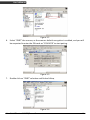
7.
Double click on “ZBBT” selection and find as follow,
Figure 3-4
Handheld Bluetooth® CCD/Laser Scanner
12
USER’S MANUAL
8.
Right click on the icon and select “Connect Bluetooth Serial Port”. Once pairing is
completed, the scanner will make low-high beep tone and the LED light in GREEN.
Note:
When scanner is set in slave mode, and the master device supports Piconet, this master
device can connect with up to 7 slave mode scanners or equipments at the same time.
Figure 3-5
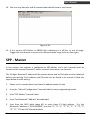
9.
Right click on icon and select “Contents” and remember your SPP Bluetooth® COM
port.
Figure 3-6
The following steps will help you verify the communication status; the actual application
depends on your application software used.
13
Handheld Bluetooth® CCD/Laser Scanner
USER’S MANUAL
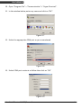
10. Open “Program File” > “Communication” > “Hyper Terminal".
11. In the window below, enter any name and click on “OK”.
Figure 3-7
12. Select the appropriate COM port as you remembered.
Figure 3-8
13. Select COM port contents as follow then click on “OK”
Figure 3-9
Handheld Bluetooth® CCD/Laser Scanner
14
USER’S MANUAL
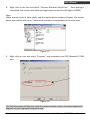
14. Test scan any barcode, and all scanned data should show in your screw.
Figure 3-10
15. If the scanner LED flashes in GREEN light indicating it is off-line, or out of range.
Trigger the scan button or move in of communication range to be on-line again.
SPP - Master
In this section, the scanner is configured as SPP-Master, and a pair barcode must be
created to the remote Bluetooth® device to which the scanner can connect.
The 12 digits Bluetooth® address of the remote device and its PIN code must be obtained
before start pairing. Such address and PIN code can be found in its manual. Follow the
steps below to start pairing.
1.
Power on the remote device and have its address ready in hand.
2.
Scan the “Start of Configuration” barcode label to enter programming mode.
3.
Scan “SPP Master” barcode label.
4.
Scan “Set Bluetooth® Address” barcode label.
5.
Scan from the ASCII table (page 62) to enter these 12 digit address. E.g. the
Bluetooth® address is “011B1345600”, scan the “0”, “0”, “1”, “1”, “B”, “1”, “3”, “4”, “5”,
“6”, “0”, “0” from ASCII barcode labels.
15
Handheld Bluetooth® CCD/Laser Scanner
USER’S MANUAL
6.
Scan “Confirm the Setting” barcode label confirm the Bluetooth® address.
Hint:
It is often found too much trouble to scan ASCII barcode label,
especially there are 12 digits to be entered. You can create a Code
39 barcode label of these 12 digits, and scan this code only for your
Bluetooth® address entry and jump to scan “Confirm the Setting”.
The Code 39 barcode label formula as follow:
BxxxxxxxxxxxxT; where “x” represents as these 12 digits.
7.
Scan “Set PIN Code” barcode label if required, otherwise jump to “Begin Pair with
Slave”.
Note:
The PIN code is an 8 digit PIN code given by remote device, you may also enter
“12345678” or ignore this entry and go directly to scan “Begin Pair with Slave” barcode
label.
8.
Scan “Confirm the Setting” barcode label to confirm the PIN code setting.
9.
Scan “Begin Pair with Slave” barcode label and a beep tone is heard to confirm
setting than start pairing.
At the same time, the scanner LED flashes in GREEN light, and if pairing successfully,
then scanner will emit Low-High beep tone, GREEN light of scanner LED is on.
If pairing failed, the scanner emits a series beep tone and you can start set-up
procedures all over again.
10. Scan “End of Configuration” to exit set up.
Handheld Bluetooth® CCD/Laser Scanner
16
USER’S MANUAL
Paging the Scanner
Paging the scanner often happens when you have two or more pairs of scanners and
communication cradles, and can not find which scanner pairs with its cradle.
Press any key on cradle, and it sends out a signal to its paired scanner, this scanner beeps
3 beeps and lights BLUE LED 3 times. But if the scanner is out of its receiving range,
then it won’t react to the cradle.
Scanning
There are two ways to scan with this device.
Handheld scanning
Hands-free scanning
Handheld Scanning
In the handheld scanning, hand held the scanner and simply aim at a barcode label and
push the scanner trigger to scan (Shown as Figure 5-1). Avoid aim vertically to the
barcode label as a total reflection might effect the scanning performance.
Figure 5-1
Hands-free Scanning
Put the scanner into the cradle for hands-free scanning, and move the barcode label
approach the scanner scanning zone (Shown as Figure 5-2).
Figure 5-2
17
Handheld Bluetooth® CCD/Laser Scanner
USER’S MANUAL
Data Transmit Method
The data transfer method includes four types, Normal (default), Out-of-Range Mode,
Standard Batch Mode and Cradle Contact Batch Mode. Users may modify this setting
according to their preferences.
Normal (default)
The scanner is not storing any data. When the scanner is within the connection range,
the scanned data will be transferred to the host computer immediately (a good beep
sound is made). If the scanner is out of its connecting range, the scanner scans and emits
4 high-tone series of beep sound, indicating data transmitting error.
Out-of-Range Mode
In this mode, the scanner is out of its wireless communication range. When scan a
barcode label, the scanner LED flashes BLUE light indicating barcode reading success, but
emit 4 high-tone series of beeps to indicate the communication breaks.
If the communication is not connected still, the scanner LED now flashes twice per
second in GREEN light, and barcode data read is saved into memory.
When scanner is back into its communication range or re-connected, the stored data is
sent when scanning next barcode label.
When data send to host, a medium-tone is heard indicating transmitting successfully.
Standard Batch Mode
Whether within the connection range or not, in Standard Batch Mode, the scanner stores
all scanned data which will be transferred to the host computer after scanning “Send
Batch Data” label.
Handheld Bluetooth® CCD/Laser Scanner
18
USER’S MANUAL
Cradle Contact Batch Mode
Working the same as Standard Batch Mode except all scanned data will only be
transferred to the host computer when the scanner is put into the cradle.
When the scanner is put into the cradle, a short-tone beep sound is made to confirm the
scanner is fitted into the cradle correctly, then the scanner LED flashes 3 times in BLUE
light and stay on, then the scanner starts transferring scanned data. Once the transfer is
done, a long medium-tone beep sound will be made.
In this mode, the scanner is NOT required to be paired with the cradle to transfer the
scanned data.
Note:
After the scanned data is transferred to the host computer, the scanner automatically
clears out its flash memory.
19
Handheld Bluetooth® CCD/Laser Scanner
USER’S MANUAL
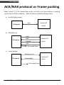
ACK/NAK protocol or Frame packing
When scanner is in SPP Master/Slave mode, and add in the data protocol or packing
could confirm the data reliability. Refer to below for different setting options:
a) No ACK/NAK protocol:
BT Scanner
b)
data
Remote BT
device
ACK/NAK only
data
BT scanner
NAK
Remote BT
Resend
device
ACK
Get a good beep
c)
Frame packing:
Data format of
BT scanner
Acknowledge
Remote BT
device
Get a good beep
Handheld Bluetooth® CCD/Laser Scanner
20
USER’S MANUAL
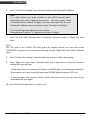
Scanner to remote application
Data Format of Packet
To send a data (barcode) to the remote application, the BT scanner has to encapsulate it:
EAH(Header)
1 byte
Size of
payload
1 byte
FEH(Format
Byte)
1 byte
Data
ID
1 byte
Data
Varies
AEH(End
of Byte)
1 byte
Reserved
Byte
1 byte
Title
Header Character (EAH)
Definition
The character ID at the head of every data.
It has to start with EAH.
Size of Payload
The encapsulated data length excluding
header character.
Differentiate data format; barcode data is
always FEH.
Format Byte (FEH)
Data ID
The number of each data. If receive the
same ID more than once, only the first one is
valid, delete the rest.
Data
Decoded barcode data
End of Byte (AEH)
Record data ends.
Reserved Byte
Reserved for future use
Example:
If barcode data is "ABCD", than sender sends out:
EAH + 9H + FEH + ID + "ABCD "+ AEH + Reserved Byte
9 = 1+1+1+4+1+1
Acknowledge packet
55H (Header )
1 byte
Data ID
1 byte
55H (end of byte)
1 byte
Example:
If scanner sends out:
EAH , 9H , FEH , 01H , "ABCD ", AEH , EEH
Remote acknowledges:
55H +01H + 55H
21
Handheld Bluetooth® CCD/Laser Scanner
USER’S MANUAL
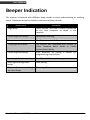
Beeper Indication
The scanner is featured with different beep sounds to assist understanding its working
status. Please see below for detailed indications of beep sounds.
Beep Sound
Single beep
Indication
Good decode, and data is either transferred
to the host computer or saved in the
memory.
2 short high-tone beeps
Low battery warning.
3 short low-tone beeps
The flash memory is full.
2 long high-tone beeps
The scanner has completed data transfer in
either Standard Batch Mode or Cradle
Contact Batch Mode.
4 short high-tone beeps
Error occurred. ex. pairing is broken up,
programming error and etc.
Low to high-tone beeps
The Bluetooth® connection is good.
Short high-low-high-tone
beeps
Short medium-tone and long
low-tone beeps
Start pairing
Powering off
Handheld Bluetooth® CCD/Laser Scanner
22
USER’S MANUAL
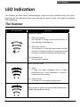
LED Indication
The scanner and the radio communication cradle are both featured with LED lights,
assisting you to understand their status during the work. Please see below for detailed
LED indications.
The Scanner
LED Illustration
Indication
GREEN LED Flash
(i) Once per second
The scanner is trying to pair with the host, or
such pairing has broken up.
(ii) Twice per second
The scanner is in Out-of-Range mode, and the
scanner is trying to build up a connection with
the host, or such connection has broken up.
(iii) Constantly on
The scanner is paired.
BLUE LED Bars Flash
(i) Once
A data has been decoded, and is either
transferred to a host computer or saved in
memory by the scanner.
(ii) Continuously
The scanner is in programming mode.
Constant Light on with First “BLUE” LED Bar
The scanner is either in Standard Batch Mode or in
Cradle Contact Batch Mode.
23
Handheld Bluetooth® CCD/Laser Scanner
USER’S MANUAL
Constant RED LED Light On
When the scanner is in the cradle, it indicates the
scanner is under charging.
Constant Light on with Third “BLUE” LED Bar
When the scanner is in the cradle, it indicates the
scanner charging is completed.
All BLUE LED Bars
(i) Constantly Light On
The scanner is transferring data to the host
computer and is in either Standard Batch
Mode or Cradle Contact Batch Mode.
(ii) Flash Twice Every 3 Seconds
The scanner has a low battery
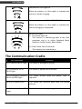
The Communication Cradle
LED Illustration
LED Flashes in BLUE Light
Indication
The cradle is waiting for pairing.
LED Constantly On in
BLUE Light
The cradle is paired with a scanner.
LED Alternately Flashes in
BLUE and RED Light
The cradle initiate failed and power reset is
required.
RED LED Flashes Once
The cradle has received data from the paired
scanner.
LED Constantly On in RED
Light
The cradle is processing pairing.
Handheld Bluetooth® CCD/Laser Scanner
24
USER’S MANUAL
Maintenance
This device provides reliable and efficient operation with a minimum of care. Although
specific maintenance is not required, as to prolong the operating life of the device, the
following precautions needs to be ensured.
Cleaning the Window and Housing
Any visibly dirty, or scratch on the scanner window will degrade reading performance,
therefore do not use abrasive wipes or tissues on the window. When the scanner is not
operating, use a soft cloth or lens tissue and gently wipe the scanning window lens.
Do not spread liquid or submerge into liquid in any circumstance.
Never use solvents (e.g., acetone, benzene, ether, or phenol-based agents) on the
housing or window, solvents may damage the housing finish or the window.
Inspecting on Interface Cables
Inspect regularly on the interface cables and its connectors, a badly worn or damaged
cable or connecters may interfere the scanning operation. Contact your distributor for
information on cable replacement.
Battery
The lifetime of rechargeable batteries would rely on the number of times the batteries
are recharged. Hence, we recommend users to keep default setting and charge in Smart
Charge mode (Refer to Section 2.1 for Charging Details). In general, we recommend
charge the scanner at the end of each working day or when the scanner requires charging.
25
Handheld Bluetooth® CCD/Laser Scanner
USER’S MANUAL
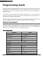
Programming Guide
Scanning a series of programming bar code labels can configure the scanner. This allows
decoding options and interface protocols to be tailored to a specific application. The
configuration is stored in non-volatile memory and will not be lost by removing power
from the scanner.
The scanner must be properly powered before programming. If you are about to
change the cradle host of parameter, the scanner and cradle must be in pairing status to
prevent failure in programming operation.
During the programming mode, the scanner will acknowledge a good and valid reading
with a short beep. It will give long beeps for either an invalid or bad reading.
Default Parameters
The factory default setting table gives the default settings of all the programmable
parameters. The default settings will be restored whenever the "Reset" programming
label is scanned and the laser scanner is in programming mode.
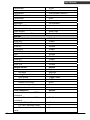
Factory Default Setting
Parameter
Radio communication
Bluetooth host
Pairing mode
Data transmit
Radio protocol timeout
Power off timeout
Encryption
Cradle Host
RS-232 communication
Baud rate
Parity
Data bits
Stop bit
RTS/CTS
Terminator
Keyboard Wedge Communication
Handheld Bluetooth® CCD/Laser Scanner
Default
Cradle Host
Unlocked
Normal
5 seconds
20 minutes
Enable
9600
none
8
1
off
<CR><LF>
26
USER’S MANUAL
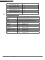
Terminator
Keyboard
Terminator
USB Communication
Terminator
Code mode
Keyboard
Wand Emulation
Wand emulation speed
Data output
Pair contact on cradle
Scanner
Decoder Selection
EAN/UPC
CODE 39
Code 32
CODABAR
ITF 2 OF 5
MSI
Chinese post code
Code 93
Code 128
EAN-128
Beeper Sound
Frequency
Duration
Operating Parameter
Scan mode
Stand mode
Header and trailer
Inter-message delay
Inter-character delay
Code Identifiers
Identifier code as ZEBEX
standard
Identifier code as AIM
standard
Code 39 identifier code
ITF 2 of 5 identifier code
Chinese post code identifier
code
27
PC/AT
US keyboard
Enter(Alpha numeric)
Enter
Scan code
US keyboard
Normal
Black=high
Enable
Default
Enable
Enable
Disable
Enable
Enable
Disable
Disable
Enable
Enable
Disable
Default
High
Medium
Default
Trigger mode
Enable
None
None
None
Default
Disable
Disable
M
I
H
Handheld Bluetooth® CCD/Laser Scanner
USER’S MANUAL
UPC-A identifier code
UPC-E identifier code
EAN-13 identifier code
EAN-8 identifier code
Codabar identifier code
Code 128 identifier code
Code 93 identifier code
MSI identifier code
11.1 Default Data Transmit Format
Code
EAN-13
EAN-8
UPCA
UPCE
CODE128
EAN128
CODE39
CODABAR
INTERLEAVED 2/5
CHINESE POST CODE
CODE93
MSI
A
E
F
FF
N
K
L
P
Message format
D1 D2 D3 D4 D5 D6 D7 D8 D9 D10 D11 D12 D13
D1 D2 D3 D4 D5 D6 D7 D8
D1 D2 D3 D4 D5 D6 D7 D8 D9 D10 D11 D12
D1 D2 D3 D4 D5 D6 D7 D8
D1-Dx
(default 3~62)
C1 D1-Dx (default 3~62)
D1-Dx
(default 3~62)
D1-Dx
(default 6~32)
D1-Dx
(default 6~32)
D1-Dx
(default 8~32)
D1-Dx
(default 3~32)
D1-Dx
(default 6~32)
Handheld Bluetooth® CCD/Laser Scanner
28
USER’S MANUAL
Program Procedure Using Barcode Manual
START
Read Start of
Configuration Label
Set All Defaults
Set Operating
Parameters
Set Serial Port
Parameters
Set Keyboard Type
Finish
Discard
Read End of
Configuration Label
Read Abort Label
Set Decoding
Parameters
END
29
Handheld Bluetooth® CCD/Laser Scanner
USER’S MANUAL
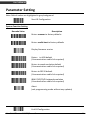
Parameter Setting
Note: Default values are highlighted in grey background.
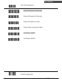
Start Of Configuration
System Function Setting
Barcode Value
Description
Return scanner to factory defaults
Return cradle host to factory defaults
Display firmware version
Return to USB default
(Communication cradle link required)
Return to wand emulation default
(Communication cradle link required)
Return to RS232 default
(Communication cradle link required)
IBM PC/AT/PS/2 Keyboard emulation
(Communication cradle link required)
Abort
(exit programming mode without any updates)
End Of Configuration
Handheld Bluetooth® CCD/Laser Scanner
30
USER’S MANUAL
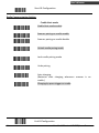
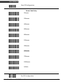
Start Of Configuration
Radio Communication Setting
Cradle Host mode
Cradle Host mode enable
Scanner pairing on cradle enable
Scanner pairing on cradle disable
Unlock cradle paring mode
Lock cradle pairing mode
Undo pairing
Auto charging
(Batteries start charging whenever scanner is on
cradle.)
Charging by press trigger on cradle
End Of Configuration
31
Handheld Bluetooth® CCD/Laser Scanner
USER’S MANUAL
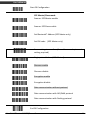
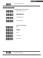
Start Of Configuration
SPP Master/Slave mode
Scanner SPP Master enable
Scanner SPP Slave enable
Set Bluetooth® Address (SPP Master only)
Set PIN code (SPP Master only)
Save setting to confirm (for address and pin code
setting required)
Begin pair with slave (SPP Master)
Discover enable
Discover disable
Encryption enable
Encryption disable
Data communication without protocol
Data communication with ACK/NAK protocol
Data communication with Packing protocol
End Of Configuration
Handheld Bluetooth® CCD/Laser Scanner
32
USER’S MANUAL
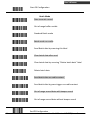
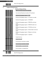
Start Of Configuration
Batch Mode
Data transmit normal
Out of range buffer enable
Standard Batch mode
Batch mode on cradle
Send Batch data by scanning this label
Clear batch data after send
Clear batch data by scanning “Delete batch data” label
Delete batch data
Send batch data on cradle contact
Send batch data by press trigger on cradle contact
Out of range resend data with beeper sound
Out of range resend data without beeper sound
End Of Configuration
33
Handheld Bluetooth® CCD/Laser Scanner
USER’S MANUAL
Start Of Configuration
Radio protocol communication parameter
Radio protocol timeout= 3 second
Radio protocol timeout= 5 second
Radio protocol timeout =8 second
Radio protocol timeout= 10 second
Radio protocol timeout =13 second
Radio protocol timeout =16 second
Radio protocol timeout= 20 second
Power off timeout=5 minute
Power off timeout=10 minutes
End Of Configuration
Handheld Bluetooth® CCD/Laser Scanner
34
USER’S MANUAL
Start Of Configuration
Power off timeout=20 minutes
Power off timeout=30 minutes
Power off timeout=1 hours
Power off by scanning this label
Link beeper enable
Link beeper disable
End Of Configuration
35
Handheld Bluetooth® CCD/Laser Scanner
USER’S MANUAL
Start Of Configuration
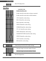
Same Code Delay
50msec
200msec
400msec
600msec
800msec
100msec
300msec
500msec
700msec
1000msec
Infinite
End Of Configuration
Handheld Bluetooth® CCD/Laser Scanner
36
USER’S MANUAL
Start Of Configuration
Operation Function Setting
Good Read Beeper Tone Selection
Medium beeper tone
High beeper tone
Low beeper tone
Speaker disable
Beeper Sound Selection
Long
Medium
Short
Ultra Short
Ultra Long
End Of Configuration
37
Handheld Bluetooth® CCD/Laser Scanner
USER’S MANUAL
Start Of Configuration
Inter Character Delay
0ms
2ms
5ms
10ms
20ms
50ms
Inter Message Delay
0 ms
100 ms
500 ms
1000 ms
End Of Configuration
Handheld Bluetooth® CCD/Laser Scanner
38
USER’S MANUAL
Start Of Configuration
Interface Settings
1.
RS-232C Interface Setting
Baud Rate
115200
19200
9600
4800
2400
1200
Parity Bit
Even parity
Odd parity
Mark parity
Space parity
None parity
Stop Bit
1 stop bit
2 stop bit
Data Bit
7 data bit
8 data bit
End Of Configuration
39
Handheld Bluetooth® CCD/Laser Scanner
USER’S MANUAL
Start Of Configuration
Handshaking Protocol
None handshaking
ACK/NAK
Xon/Xoff
RTS/CTS
Enable BEEPER ON<BEL> CHARACTER
Ignore Beep on<BEL> character
Disable ACK/NAK timeout beeper
Enable ACK/NAK timeout beeper(three sound
beeper sound)
ACK/NAK response time 300ms
ACK/NAK response time 2s
ACK/NAK response time 500ms
ACK/NAK response time 3s
ACK/NAK response time 1s
ACK/NAK response time 5s
ACK/NAK response time infinity
End Of Configuration
Handheld Bluetooth® CCD/Laser Scanner
40
USER’S MANUAL
Start Of Configuration
Message Terminator
RS-232 message terminator—none
RS-232 message terminator—CR/LF
RS-232 message terminator—C
RS-232 message terminator—LF
RS-232 message terminator—H tab
RS-232 message terminator—STX/ETX
RS-232 message terminator—EOT
End Of Configuration
41
Handheld Bluetooth® CCD/Laser Scanner
USER’S MANUAL
Start Of Configuration
2.
Keyboard Wedge Setting
Keyboard Wedge Setting
IBM PC/AT/PS/2 Keyboard emulation
International Keyboard mode.( ALT method).
Keyboard language support---USA
Keyboard language support---UK send scan code
Keyboard language support---GERMANY
Keyboard language support---FRENCH send scan
code
Keyboard language support---SPANISH send scan
code
Keyboard language support---ITALIAN send scan
code
Keyboard language support---Switzerland send scan
code
Keyboard language support---Belgium send scan
code
Keyboard language support---Japanese
Capital lock on
Capital lock off
Function key emulation enable
Function key emulation disable
Send number as normal data
Send number as keypad data
End Of Configuration
Handheld Bluetooth® CCD/Laser Scanner
42
USER’S MANUAL
Start Of Configuration
Message Terminator
Keyboard terminator---none
Keyboard terminator---Enter
Keyboard terminator---H-TAB
End Of Configuration
43
Handheld Bluetooth® CCD/Laser Scanner
USER’S MANUAL
Start Of Configuration
3.
USB Interface Setting
USB interface
International Keyboard mode.( ALT method).
Keyboard language support---USA
Keyboard language support---GERMANY
Keyboard language support---FRENCH send scan
code
Keyboard language support---SPANISH send scan
code
Keyboard language support---Japanese
Message Terminator
Keyboard terminator---none
Keyboard terminator---Enter
Keyboard terminator---H-TAB
End Of Configuration
Handheld Bluetooth® CCD/Laser Scanner
44
USER’S MANUAL
Start Of Configuration
4.
Wand Emulation Setting
Wand emulation is not supported as standard, if needed, please contact your distributor.
Wand Emulation
All barcode will be decoded and transmitted in that
symbology
Enable Wand output data format as CODE39
Wand emulation data output black=high
Scan this bar code to set quiet zones and
spaces low and bars =high.
Wand emulation data output black=low
Scan this bar code to set quiet zones and
spaces high and bars=low
Idle = high
Idle state refers to the TTL logic level of the
Wand Emulation signal when not in use
Idle = low
Idle state refers to the TTL logic level of the
Wand Emulation signal when not in use
End Of Configuration
45
Handheld Bluetooth® CCD/Laser Scanner
USER’S MANUAL
Start Of Configuration
Wand Emulation (Cont’d)
Wand emulation speed-----Low
This option allows the transmission of wand
emulation at 1ms narrow element width
Wand emulation speed-----medium
This option allows the transmission of wand
emulation at 600us narrow element width
Wand emulation speed-----normal
Wand emulation speed-----high
This option allows the transmission of wand
emulation at 300us narrow element width
Wand emulation speed-----higher
This option allows the transmission of wand
emulation at 100 us narrow element width
Wand emulation narrow/wide ratio 1:2
Wand emulation narrow/wide ratio 1:3
End Of Configuration
Handheld Bluetooth® CCD/Laser Scanner
46
USER’S MANUAL
Start Of Configuration
The Symbologies
CODABAR Parameter Setting
Codabar enable
Codabar start/stop character transmission----DC1~DC4
CODABAR disable
Codabar start/stop character transmission----a/t,b/n,c/*,d/e
Codabar start/stop character transmission-----none
Codabar maximum length setting
Codabar start/stop character transmission----A,B,C,D
Codabar minimum length setting
Save setting to confirm (for length setting)
Codabar concatenation disable
Validate modulo 16 and transmit
Codabar concatenation enable
Codabar data redundant check=off
No check character
Codabar data redundant check=1
Validate modulo 16,but don’t transmit
Codabar data redundant check=2
End Of Configuration
47
Handheld Bluetooth® CCD/Laser Scanner
USER’S MANUAL
Start Of Configuration
Code 39 Parameter Setting
Code 39 enable
FULL ASCII code 39
Code 39 disable
Code 39 start/stop character transmission
Code 39 start/stop character without transmission
Code 32 enable
Code 32 disable
Code 39 check digit calculate and transmit
No check character
Code 39 check digit calculate but without transmit
Code 39 data redundant check=off
Code 39 data redundant check=1
Code 39 data redundant check=2
End Of Configuration
Handheld Bluetooth® CCD/Laser Scanner
48
USER’S MANUAL
Start Of Configuration
Code 39 Parameter Setting (Cont’d)
Code 39 maximum length setting
Code 39 minimum length setting
Save setting to confirm (for length setting)
Code 39 concatenation enable
Code 39 concatenation disable
Code 32 (Italian pharmacy) transmit “A” character
Code 32 (Italian pharmacy) without transmit ”A”
character
End Of Configuration
49
Handheld Bluetooth® CCD/Laser Scanner
USER’S MANUAL
Start Of Configuration
Code 93 Parameter Setting
Code 93 enable
Code 93 disable
Code 93 data redundant check=off
Code 93 data redundant check=1
Code 93 data redundant check=2
Code 93 maximum length setting
Code 93 minimum length setting
Save setting to confirm (for length setting)
Code 93 check digit calculate but without transmit
Code 93 check digit not calculate and without
transmit
Code 93 check digit calculate and transmit
End Of Configuration
Handheld Bluetooth® CCD/Laser Scanner
50
USER’S MANUAL
Start Of Configuration
Code 128
Code 128 enable
Code 128 disable
EAN 128 enable
EAN 128 disable
Code128 FNC2 concatenation enable
Code128 FNC2 concatenation disable
Code 128 data redundant check=off
Code 128 data redundant check=1
Code 128 data redundant check=2
Code 128 maximum length setting
Code 128 minimum length setting
Save setting to confirm (for length setting)
End Of Configuration
51
Handheld Bluetooth® CCD/Laser Scanner
USER’S MANUAL
Start Of Configuration
Chinese Post Code
Chinese post code enable
Chinese post code disable
Chinese post codedata redundant check=off
Chinese post code data redundant check=1
Chinese post codedata redundant check=2
Chinese post code maximum length setting
Chines post code code minimum length setting
Save setting to confirm (for length setting)
End Of Configuration
Handheld Bluetooth® CCD/Laser Scanner
52
USER’S MANUAL
Start Of Configuration
MSI/Plessy
MSI enable
MSI disable
MSI data redundant check= off
MSI data redundant check=1
MSI data redundant check=2
MSI/PLESSY maximum length setting
MSI/PLESSY minimum length setting
Save setting to confirm (for length setting)
MSI/Plessy double check digit calculate but not
transmit
MSI/Plessy double check digit calculate and both
transmit
MSI/Plessy double check digit without calculate and
transmit
MSI/Plessy single check digit calculate but without
transmit
MSI/Plessy double check digit calculate but only first
digit transmit
MSI/Plessy single check digit calculate and
transmit
End Of Configuration
53
Handheld Bluetooth® CCD/Laser Scanner
USER’S MANUAL
Start Of Configuration
ITF 2 of 5
ITF 2 of 5 enable
ITF 2 of 5 disable
IATA code enable
IATA disable
ITF 2 of 5 check digit calculate and transmit
ITF 2 of 5 check digit calculate but without transmit
ITF 2 of 5 no check character
ITF 2 of 5 one Fixed length setting
ITF 2 of 5 two Fixed length setting
ITF 25 data redundant check=off
ITF25 data redundant check=1
ITF25 data redundant check=2
ITF 2 of 5 code minimum length setting
ITF 2 of 5 length variable
ITF 2 of 5 code maximum length setting
Save setting to confirm (for length setting)
End Of Configuration
Handheld Bluetooth® CCD/Laser Scanner
54
USER’S MANUAL
Start Of Configuration
UPC/EAN/JAN
EAN convert to ISSN/ISBN enable
EAN convert to ISSN/ISBN disable
UPC/EAN/JAN ALL ENABLE
EAN-8 ENABEL
UPC-A AND EAN-13 ENABLE
EAN-8 OR EAN-13 ENABLE
UPC-A AND UPC-E ENABLE
UPC-E ENABLE
EAN-13 ENABLE
UPC-A ENABEL
UPC/EAN Addendum Disable
Add on 5 only
Add on 2 only
Add on 2 or 5
Force UPC-E to UPC-A format enable
Force UPC-E to UPC-A format disable
End Of Configuration
55
Handheld Bluetooth® CCD/Laser Scanner
USER’S MANUAL
Start Of Configuration
UPC/EAN/JAN (Cont’d)
Force UPC-A to EAN-13 format enable
Force UPC-A to EAN-13 format disable
Transmit UPC-A check digit enable
Transmit UPC-A check digit disable
Transmit UPC-E check digit enable
Transmit UPC-E check digit disable
Transmit UPC-E leading character enable
Transmit UPC-E leading character disable
Transmit UPC-A leading character enable
Transmit UPC-A leading character disable
Transmit EAN-13 check digit disable
Transmit EAN-13 check digit enable
Transmit EAN-8 check digit enable
Transmit EAN-8 check digit disable
End Of Configuration
Handheld Bluetooth® CCD/Laser Scanner
56
USER’S MANUAL
Start Of Configuration
UPC/EAN/JAN (continued)
force EAN-8 to EAN-13 format enable
force EAN-8 to EAN-13 format disable
EAN-13 country code first “0” can transmitted
EAN-13 country code first:”0” can’t transmitted
Add-on format with separator
Add-on format without separator
EAN/UPC +add-on (none mandatory)
EAN/UPC +add-on ( mandatory)
End Of Configuration
57
Handheld Bluetooth® CCD/Laser Scanner
USER’S MANUAL
Start Of Configuration
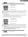
Data Editing
Identifier Code
Disable identifier code
Enable identifier code table as factory standard
Enable identifier code table as AIM standard.
UPC-A identifier code setting
EAN-13 identifier code setting
EAN-8 identifier code setting
CODE 39 identifier code setting
CODABAR identifier code setting
ITF 2 of 5 identifier code setting
CODE 128 identifier code setting
CHINESE POST CODE identifier code setting
CODE 93 identifier code setting
UPC-E identifier code setting
MSI identifier code setting
Save setting to confirm (for length setting)
Add code length as header enable (2 Bytes)
Add code length as header disable (2 Bytes)
End Of Configuration
Handheld Bluetooth® CCD/Laser Scanner
58
USER’S MANUAL
Start Of Configuration
Header And Trailer
Header (Preamble)
Trailer (Postamble)
Save setting to confirm
The Header and Trailer allows you to append a header and/or a trailer to every message
transmitted via serial port, USB or the keyboard port. There is no restriction in selecting
header or trailer characters as far as the sum of the lengths of header and trailer is not
larger than 10 digits.
1.) Select either header or trailer you are going to program by scanning the
corresponding label.
2.) Scan your ideal character(s) from the enclosed ASCII table to set as header or trailer
(be sure to enable full ASCII code 39 option before starting).
3.) Read the “Save setting to confirm” label to confirm the programming.
Truncate Character
Truncate header character
Truncate trailer character
Save setting to confirm
The Truncate character setting allows you to truncate a number of symbology
header or trailer. When you do so, the specific character you select is deleted
from the symbology.
1.)
Scan the “Truncate header character” or “Truncate trailer character” label.
2.)
Scan two barcode value from the full ASCII code table (0~9). For example,
if you want to omit the number 2, then scan ”0” and “2.
3.)
Scan the ”Save setting to confirm” label.
End Of Configuration
59
Handheld Bluetooth® CCD/Laser Scanner
USER’S MANUAL
Start Of Configuration
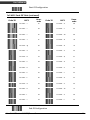
Full ASCII Code 39 Table
Code 39
ASCII
Hexa
code
Code 39
ASCII
Hexacode
Full ASCII ---NUL
00
Full ASCII ---SI
Function key-----“Shift”
0F
Full ASCII ---SOH
Function key-----“Ins”
01
10
Full ASCII ---STX
Function key-----“Del”
02
Full ASCII ---DLE
Function key----“5(num)”
Full ASCII ---DC1
Function key-----“F1”
Full ASCII ---ETX
Function key-----“Home”
03
Full ASCII ---DC2
Function key-----“F2”
12
Full ASCII ---EOT
Function key-----“End”
04
Full ASCII ---DC3
Function key-----“F3”
13
Full ASCII ---ENQ
Function key-----“Up
arrow”
Full ASCII ---ACK
Function key-----“Down
arrow”
Full ASCII ---BEL
Function key-----“Left
arrow”
Full ASCII ---BS
Function key----“Backspace”
Full ASCII ---HT
Function key-----“TAB”
05
Full ASCII ---DC4
Function key-----“F4”
14
06
Full ASCII ---NAK
Function key-----“F5”
15
07
Full ASCII ---SYN
Function key-----“F6”
16
08
Full ASCII ---ETB
Function key-----“F7”
17
09
Full ASCII ---CAN
Function key-----“F8”
18
Full ASCII ---LF
Function key-----“Enter
(alpha numeric”
Full ASCII ---VT
Function key-----“right
arrow”
Full ASCII ---FF
Function key-----“PgUp”
0A
Full ASCII ---EN
Function key-----“F9”
19
0B
Full ASCII ---SUB
Function key-----“F10”
1A
0C
Full ASCII ---ESC
Function key-----“F11”
1B
Full ASCII ---CR
Function key----“Enetr(num.)”
Full ASCII ---SO
Function key-----“PgDn”
0D
Full ASCII ---FS
Function key-----“F12”
1C
0E
Full ASCII ---GS
Function key-----“ESC”
1D
End Of Configuration
Handheld Bluetooth® CCD/Laser Scanner
11
60
USER’S MANUAL
Start Of Configuration
Full ASCII Code 39 Table (continued)
HexaCode 39
ASCII
code
Code 39
ASCII
Hexacode
Full ASCII ---RS
Function key-----“CTL(L)”
1E
Full ASCII ----
2D
Full ASCII ---US
Function key-----“ALT(L)”
1F
Full ASCII ---.
2E
Full ASCII ---SP
20
Full ASCII ---/
2F
Full ASCII ---!
21
Full ASCII ---0
30
Full ASCII ---“
22
Full ASCII ---1
31
Full ASCII ---#
23
Full ASCII ---2
32
Full ASCII ---$
24
Full ASCII ---3
33
Full ASCII ---%
25
Full ASCII ---4
34
Full ASCII ---&
26
Full ASCII ---5
35
Full ASCII ---‘
27
Full ASCII ---6
36
Full ASCII --- (
28
Full ASCII ---7
37
Full ASCII ---)
29
Full ASCII ---8
38
Full ASCII ---*
2A
Full ASCII ---9
39
Full ASCII ---+
2B
Full ASCII ---:
3A
Full ASCII ---,
2C
Full ASCII ---;
3B
End Of Configuration
61
Handheld Bluetooth® CCD/Laser Scanner
USER’S MANUAL
Start Of Configuration
Full ASCII Code 39 Table (continued)
Code 39
ASCII
Hexacode
Code 39
ASCII
Hexacode
Full ASCII ---<
3C
Full ASCII ---K
4B
Full ASCII ---=
3D
Full ASCII ---L
4C
Full ASCII --->
3E
Full ASCII ---M
4D
Full ASCII ---?
3F
Full ASCII ---N
4E
Full ASCII ---@
40
Full ASCII ---O
4F
Full ASCII ---A
41
Full ASCII ---P
50
Full ASCII ---B
42
Full ASCII ---Q
51
Full ASCII ---C
43
Full ASCII ---R
52
Full ASCII ---D
44
Full ASCII ---S
53
Full ASCII ---E
45
Full ASCII ---T
54
Full ASCII ---F
46
Full ASCII ---U
55
Full ASCII ---G
47
Full ASCII ---V
56
Full ASCII ---H
48
Full ASCII ---W
57
Full ASCII ---I
49
Full ASCII ---X
58
Full ASCII ---J
4A
Full ASCII ---Y
59
End Of Configuration
Handheld Bluetooth® CCD/Laser Scanner
62
USER’S MANUAL
Start Of Configuration
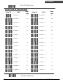
Full ASCII Code 39 Table (continued)
HexaCode 39
ASCII
code
Code 39
ASCII
Hexacode
Full ASCII ---Z
5A
Full ASCII ---i
69
Full ASCII ---[
5B
Full ASCII ---j
6A
Full ASCII ---\
5C
Full ASCII ---k
6B
Full ASCII ---]
5D
Full ASCII ---l
6C
Full ASCII ---^
5E
Full ASCII ---m
6D
Full ASCII ---_
5F
Full ASCII ---n
6E
Full ASCII ---`
60
Full ASCII ---o
6F
Full ASCII ---a
61
Full ASCII ---p
70
Full ASCII ---b
62
Full ASCII ---q
71
Full ASCII ---c
63
Full ASCII ---r
72
Full ASCII ---d
64
Full ASCII ---s
73
Full ASCII ---e
65
Full ASCII ---t
74
Full ASCII ---f
66
Full ASCII ---u
75
Full ASCII ---g
67
Full ASCII ---v
76
Full ASCII ---h
68
Full ASCII ---w
77
End Of Configuration
63
Handheld Bluetooth® CCD/Laser Scanner
USER’S MANUAL
Start Of Configuration
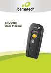
Full ASCII Code 39 Table (continued)
HexaCode 39
ASCII
code
Code 39
ASCII
Hexacode
Full ASCII ---x
78
Full ASCII ---|
7C
Full ASCII ---y
79
Full ASCII ---}
7D
Full ASCII ---z
7A
Full ASCII ---~
7E
Full ASCII ---{
7B
Full ASCII ---DEL
7F
End Of Configuration
Handheld Bluetooth® CCD/Laser Scanner
64