1
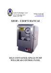
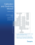
Axiom Technologies L.L.C
15731 W. Hardy Road, Suite 7
Houston, Texas 77060
Telephone: 281 931 0907
Fax: 281 231 6562
www.axiomsafe ty.com
XP3
USER’S MANUAL
COMPACT
HIGH AND LOW PRESSURE
SHUTDOWN SYSTEM
Axiom Technologies
XP3 User’s Manual
15731 W. Hardy Rd., Suite 7, Houston, Texas 77060
Phone 281 931 0907
GENERAL
The XP3 alarm and shutdown system is a self supported, compact shutdown device that
has been designed to provide a safe and reliable mean to monitor temperature or pressure
on a production process and initiate a shutdown if the reading exceeds the pre-set limits
of operation.
The system has been built to withstand the adverse conditions of the oil-field
environment and provides a straightforward interface with the operator. Abnormal
conditions are indicated by indicator lamps (LEDs), each associated with a label
indicating the condition detected.
Powered by lithium batteries, the system is expected to operate for about five years
without replacing batteries and besides normal periodical functionality test there is little
or no maintenance needed.
INSTALLATION
Typically, the XP3 is shipped with the battery module installed in the “storage position”
for shipment. Remove the four studs holding the battery module, rotate the module 180º
and carefully re-install as shown on page 7 of this manual. The XP3 is now energized
and the green LED blinking once every two seconds.
Indicator LEDs
“Reset” – “Test”
Switch
Low Press/Temp
Alarm Setting
Solenoid Valve
Sensing Port
High Press/Temp
Alarm Setting
Fig. 1 XP3 General Layout
The unit can be wall mounted or mounted directly on the process line. The box is
provided with a small drain hole at the bottom to drain condensation. Do not mount the
Manual Rev. 3E
February 07, 2008
Page 2 OF 8
Axiom Technologies
XP3 User’s Manual
15731 W. Hardy Rd., Suite 7, Houston, Texas 77060
Phone 281 931 0907
XP3 sideways or upside down as this may allow rainwater to ingress and accumulate in
the enclosure.
XP3 / Pressure Sensing
Connect monitored pressure to Sensing Port. Sensed pressure is not to exceed 10% over
full scale as this would cause damage in the instrument and void warranty. If the flow is
prone to pressure spikes, a pulsation dampener is to be installed between the sensing port
and sensed fluid. It is recommended that an isolation valve is installed between the
sensing port and process to allow for maintenance and testing.
NOTE: XP3 DEVICE IS TO BE MOUNTED UPRIGHT ON
VERTICAL POSITION ONLY.
NOTES:
Do not exceed rated range. When connecting pressure bourdon assembly
(bottom of XP3), dope or use teflon tape on connection threads.
Use wrench on shank to tighten or loosen bourdon connection. Do not twist
case when installing, this will damage internal components and void
warranty. Do not over-tighten.
Connecting the Solenoid Valve.
The typical connection the solenoid valve is as follows
Port 1 (normally closed)
Port 2 (common)
Port 3 (normally open)
Supply Pneumatic Pressure (100 PSI Typ.)
Actuator
Exhaust
Port No. 1 - Pneumatic Supply
100 PSI Typ.
Port No. 2 - To Actuator.
Note:
Port numbers are stamped
near the ports
Port No. 3 - Exhaust
Fig. 2 Solenoid pneumatic/hydraulic typical connection
Manual Rev. 3E
February 07, 2008
Page 3 OF 8
Axiom Technologies
XP3 User’s Manual
15731 W. Hardy Rd., Suite 7, Houston, Texas 77060
Phone 281 931 0907
Adjusting High and Low limits
Facing the dial, left knob adjusts the “Low Limit” while the “High Limit” contact is
controlled by the knob on the right. To set the limit contacts simply turn the knob to the
desired position in the scale.
OPERATION
The system can be commanded to “Reset” or “Test” by pressing the toggle switch up or
down respectively. By pushing to “Reset” the operator commands the unit to return to
the flowing condition while the “Test” function allows the operator to see the last
recorded cause of shutdown (corresponding LED blinks fast) and then the system
proceeds to slow blink each red LED to confirm all indicator circuits are operating
normally.
The system is shipped in the “RESET” condition. The needle of the gauge touching
either the “Low” or “High” set point causes the XP3 to switch the solenoid valve into
“shutdown”. The corresponding alarm LED will blink once a second to indicate the
actual cause of the shutdown even if the alarm goes away or another alarm is later
detected.
EXAMPLE. If an XP3 senses a “High Pressure” in a production line it will cause a
shutdown and the “High Pressure” LED will blink. After a number of hours, because of
the shutdown, the sensed pressure may fall to the point where the high pressure clears and
the needle of the gauge is now touching the low pressure alarm. In this case the XP3 will
continue to flash the “High Pressure” alarm LED until the operator presses “Reset”. If
the operator wants to confirm the cause of alarm, even after the system is back to normal,
he just need to press “Test” and the XP3 will blink the “High Pressure” LED to show the
last recorded cause of shutdown.
After the XP3 is installed, the operator is to set the high and low alarm settings and open
the isolation valve to allow pressure into the sensing port.
If the gauge is on alarm at the time the operator presses “Reset” the existing alarm will be
ignored for 30 minutes to allow the process to return to normal; there is no need to
disturb the set-point before restoring the process. It is recommended not to move the set
points out of the alarm condition as this involves the risk of the operator forgetting to
return the alarms to the proper setting once the process returns to normal. If more than 30
minutes is needed then it is suggested that the operator presses “Reset” again before the
time expires for re-starting the 30 minutes counting.
If the pressure (or temperature) returns to normal before 30 the minutes expires, the XP3
will re-arm itself and will initiate shutdown again if an alarm is sensed.
Manual Rev. 3E
February 07, 2008
Page 4 OF 8
Axiom Technologies
XP3 User’s Manual
15731 W. Hardy Rd., Suite 7, Houston, Texas 77060
Phone 281 931 0907
Time Delay Input
The XP3 can be configured to have a 15 seconds time delay before initiating shutdown.
This is mainly used in situations where the nature of the process causes pressure
excursions that are not cause for shutdown if they last for just a couple of seconds. The
time delay may be individually set by means of jumping JMP2 for having a delay on the
Low Alarm and JMP1 for having a delay on the High Alarm. Each XP3 is shipped with
the shunt connector attached to one pin on the jumper circuit (no time delay). To activate
the time delay the operator is to install the shunt across the pins of JMP2 for the low
pressure andJMP1 if the delay is to be set for the high pressure.
Fig 3 JMP1 and JMP2 are located at the bottom left corner of control board.
MAINTENANCE
The XP3 requires little maintenance but a minimum of a monthly visual examination and
testing is recommended to insure that the unit as well as the systems associated with the
safety shutdown is operating properly.
It is recommended that once a year the gauge pointer and High and Low limit points be
cleaned with a non residue contact cleaner to insure optimum performance.
Manual Rev. 3E
February 07, 2008
Page 5 OF 8
Axiom Technologies
XP3 User’s Manual
15731 W. Hardy Rd., Suite 7, Houston, Texas 77060
Phone 281 931 0907
Inspecting the XP3
The XP3 is to be examined periodically and operation may be confirmed by observing
the “Syst.” LED for verifying it blinks every two seconds. (Sunny days may require the
operator to shade the “Syst.” LED to see it blinking).
The XP3 is to be inspected also to confirm that the face of the gauge is clean and the
pressure/temperature indication is clearly visible. If evidence of contamination is seen on
the needle of the gauge or set points, cleaning is needed to insure that contact will be
made if an alarm condition is reached.
To clean the contact points or needle use a soft cloth and contact cleaner fluid. Do not
use abrasives materials or fluids as they will cause damage and reduce system’s
reliability.
Note
Avoid opening the enclosure in a rainy or dusty environment.
The batteries are expected to have a life of about 5 years before replacement is needed.
The XP3 routinely read battery voltages and provides warning if the batteries need
replacement. When the batteries are beginning to go low the XP3 will blink the “Lo
Batt” LED to indicate that battery replacement is needed. If the batteries are not replaced
within a few days the XP3 will cause a “Lo Batt.” shutdown as further reduction in
voltage may prevent the system from protecting the process.
WARNING - EXPLOSION HAZARD
BATTERIES MUST ONLY BE CHANGED IN AN AREA
KNOWN TO BE NON-HAZARDOUS. REPLACE BATTERY
MODULE WITH AXIOM TECHNOLOGIES PART
NUMBER AT-LBP-36144.
Manual Rev. 3E
February 07, 2008
Page 6 OF 8
Axiom Technologies
XP3 User’s Manual
15731 W. Hardy Rd., Suite 7, Houston, Texas 77060
Phone 281 931 0907
REPLACING THE BATTERY MODULE
Fig. 4
Remove screws from cover
Fig. 5
Open front cover
Fig. 6
Battery module is on top of box
Fig. 7
Unscrew the four (4) nylon spacers
holding the battery module.
Fig. 8 Pull old battery module out and
return for safe disposal.
Fig. 9
Align the new battery module
with threaded studs and push
it in place gently.
Manual Rev. 3E
February 07, 2008
Page 7 OF 8
Axiom Technologies
XP3 User’s Manual
15731 W. Hardy Rd., Suite 7, Houston, Texas 77060
Fig. 10 Re-install nylon spacers to hold
the battery module in place.
Tighten by hand only.
Phone 281 931 0907
Fig. 11 Cover is to be closed and secured with
front screws to insure proper sealing
and protection from environment .
WARNING
DO NOT ATTEMPT TO RECHARGE BATTERY MODULE
AS THIS MAY TRIGGER AN UNSTABLE CONDITION
WITHIN THE LITHIUM CELLS AND CAUSE AN
EXPLOSION
Return used battery modules to Axiom Technologies for safe
disposal.
XP3 - ENVIRONMENTAL SPECIFICATIONS
Temperature range
Humidity range
Altitude
Hazardous Area Classification
:
:
:
:
-40 to +60C
0 To 95% max., non condensing
2,000 m. max.
Suitable for Class I, Division 2, Groups C & D,
Hazardous Locations. Temp. code T3C
XP3 - PRESSURE RATINGS
Sensing Pressure : Ranges of up to 20,000 psi max
Solenoid Valve Pressure : 100 psi max. (standard ), up to150 psi available
XP3 - ELECTRICAL RATINGS
Electrical Source : Dual voltage lithium battery module3.6 & 14.4 VDC
Current consumption : 285 mA max. on 3.6VDC Circuits
435 mA (3 A max. pulse) on 14.4VDC Circuits
Manual Rev. 3E
February 07, 2008
Page 8 OF 8