1
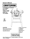
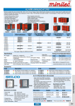
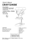
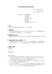
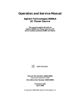
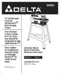
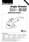
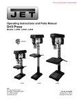
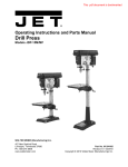
.JET
EQUIPMENT &TOOLS
OPERATOR'S MANUAL
JDP-8 DRILL PRESS
Stock No. M-354066
EGUIPMENT
a TOOLS, INC.
A W'H . Walter Meier Holding Company
.lET
P.O.BOX 1349
AUBURN, WA98071-1349
[253] 351-6000
FAX [253]
939-8001
6/90
OPERATING INSTRUCTIONS
TABLE OF CONTENTS
Before operating the unit, please read this
manual thoroughly, and retain it for future
reference.
General Safety Instructions. . . . . . . . . . . . . . 2
Additional Safety Rules. . . . . . . . . . . . . . . . . 3
Specifications.
We thank you for your purchase of a JET Drill
Press. It has been designed, engineered and
manufactured to give you the best possible
dependability and performance. However
we'd like to remind you that faultless running is
entirely dependent upon rational use and
Careful maintenance, which will also spare the
user time consuming delays and costly
repairs.
........................ 4
Electrical Requirements
5
Getting to Know Your Drill Press.
.................. 7
Assembly Instructions
Operations
Installing Chuck
Removing Chuck & Arbor. . . .
Depth Stop. . . . . . . . . . . . . . .
Spindle Speeds. . . . . . . . . . .
Changing Spindle Speeds and
Tensioning Belt
Return Spring Adjustment. . .
Basic Operational Hints
Lubrication.
......... 6
8
. . . . . . . . .. 8-9
............ 9
............ 9
9-10
. . . . . . . . . . . 11
11
. . . . . . . . . . . . . . . . . . . . . . . . . 11
Electrical Breakdown
Parts Breakdown.
Parts List.
12
. . . . . . . . . . . . . . . . . . . . 13
. . . . . . . . . . . . . . . . . . . . . ..
14-15
WARNING!
Some dust created by power sanding, sawing,
grinding, drilling, and other construction activities
contains chemicals known [to the Sate of California]
to cause cancer, birth defects or other reproductive
harm. Some examples of these chemicals are:
. Lead from lead-based paints,
. Crystalline silica from bricks and cement and other
masonry products, and
. Arsenic and chromium from chemically treated
lumber.
The model and serial numbers of your set are
located on the front of the belt cover.
Record the serial number in the space
provided below. Refer to these numbers in
any correspondence relating to this product:
MODEL:
Your risk from these exposure varies, depending on
SERIAL N0.:
how often you do this type of work. To reduce your
exposure to these chemicals: work in a well ventilated
area, and work with approved safety equipment, such
as those dust masks that are specially designed to
filter out microscopic
1
particles.
GENERAL SAFETY INSTRUCTIONS
11. TURN POWER OFF. NEVER LEAVE
TOOL RUNNING UNATTENDED. Do not
leave tool until it comes to a complete stop.
1. KEEP GUARDS IN PLACE. Safety guards
must be kept in place and in working order.
2. REMOVE ADJUSTING KEYS AND
WRENCHES. Check to see that the chuck
keys and adjusting wrenches are removed
from tool before turning it on.
12. KEEP WORK AREA CLEAN. Cluttered
areas and benches invite accidents.
3. REDUCE THE RISK OF UNINTENTIONAL
ST ARTING. Make sure switch is in the
"OFF" position before plugging in the tool.
13. DO NOT USE IN DANGEROUS
ENVIRONMENT. Do not use power tools
in damp or wet locations or expose them to
rain. Keep work area well lighted.
4. DO NOT FORCE TOOLS. They will do the
job better and safer at the rate for which
they were designed.
14. KEEP CHILDREN AWAY. All visitors
should be kept at a safe distance from
work area.
5. USE RIGHT TOOL. Do not force tool or
attachment to do a job for which it was not
designed.
15. MAKE WORKSHOP CHILD PROOF. Use
padlocks, master switches, and remove
starter keys.
6. SECURE WORK. Use clamps or a vise to
hold work when practical. NEVER use
hands to hold workpiece.
16. WEAR PROPER APPAREL. Loose
clothing, gloves, neckties, rings, bracelets
or other jewelry may get caught in moving
parts. Non slip footwear is recommended.
Wear protective hair covering to contain
long hair.
7. MAINTAIN TOOLS WITH CARE. Keep
tools sharp and clean for the best and
safest performance. Follow instructions for
lubricating and changing accessories.
17. ALWAYS USE SAFETY GLASSES AND
DUST MASKS. Use face or dust mask if
cutting operation is dusty. Every day
eyeglasses only have impact resistant
lenses, they are NOT safety glasses.
8. DISCONNECT TOOLS FROM POWER.
Before servicing, or when changing
accessories such as bits, blades, cutters,
etc.
18. DO NOT OVERREACH. Keep proper
footing and balance at all times.
9. USE RECOMMENDED ACCESSORIES.
Consult the owner's manual for
recommended accessories. The use of
improper accessories may cause injuries to
operator.
19. NEVER STAND ON TOOL. Serious
injuries could occur if a moving part is
unintentionally contacted.
10. CHECK DAMAGED PARTS. A guard or
any part that is damaged should be
carefully checked to determine that it will
operate properly and perform its intended
function. Check for alignment of moving
parts, binding of moving parts, breakage of
parts, mounting, and any other conditions
that may affect its operation. A guard or
any part that is damaged shoulq be
properly repaired or replaced.
20. WQOD DUST CREATED BY CERTAIN
WOODWORKING TOOLS CAN BE
HAZARDOUS TO YOUR HEALTH.
Operate machinery in a well ventilated
area. Use of a dust collection system is
highly recommended.
2
ADDITIONAL SAFETY RULES FOR DRILL PRESSES
1. Operate drill presses only if you are familiar
with its operation. If not, ask a qualified
user.
2. Always shut off power to machine before
making any adjustments.
3. Machine must be properly grounded. Be
sure to check that electrical connections
are compatible with machine.
4. Always check tightness of drill bit before
operating. Failure to do so could cause
damage to machine and/or operator.
5. Always remove chuck key from chuck
before starting machine.
6. Always adjust table and/or depth stop to
prevent drilling into table. It is highly
recommended to use a backing piece when
drilling through workpiece.
7. Secure workpiece to table with clamps or a
vise to prevent rotating with the drill bit.
WARNING :Do not wear gloves when operating
drill press; serious injury could
result.
WARNING :Wear proper eye protection when
operating. this or any power tool.
3
JET DRILL PRESSES
SPECIFICATIONS:
Stock Number:
Swing:
Type:
Drilling Capacity:
Chuck Size:
Spindle Travel:
Spindle Distance to
Base:
Spindle Distance to
Table:
Table Size Diameter:
Table Tilt:
Spindle Taper:
Column Diameter:
Spindle Speed:
Spindle RPM:
Overall Height:
Base Size:
Motor:
Net Weight (approx):
Shipping Weight (approx):
JDP-8
354066
8"
Bench
3/8"
1/2"
2"
10 1/8"
7 3/16"
63/8"
:t 45°
JT#33
1 7/8"
5
620-3100
22 1/2"
7 3/8" x 11 1/2"
1/6HP, 1Ph
115V
U.L. Listed
401bs.
441bs.
4
electrical requirements
WARNING: TO AVOID INJURY FROM UNEXPECTED STARTUP, DO NOT USE BLOWER OR
WASHING MACHINE MOTORS OR ANY MOTOR
WITH AN AUTOMATIC RESET OVERLOAD PROTECTOR.
This power tool is equipped with a 3-conductor cord
and grounding type plug. approved by Underwriters'
Laboratories and the Canadian Standards Association.
The ground conductor has a green jacket and is attached to the tool housing at one end and to the ground
prong in the attachment plug at the other end.
This plug requires a mating 3-conductor grounded type
outlet as shown.
CONNECTING TO POWER
SOURCE OUTLET
If the outlet you are planning to use for this power tool
is of the two prongtype. DO NOT REMOVE OR ALTER
THE GROUNDING PRONG IN ANY MANNER. Use
an adapter as shownand always connect the grounding
lug to known ground.
It is recommendedthat you have a qualified electrician
replace the TWO prong outlet with a properly grounded
THREE prong outlet.
This machine must be grounded while in use to protect
the operator from electric shock.
Plug power cord into a 110-120V properly grounded
type outlet protected by a 15-amp. dual element time
delay or Circuit breaker.
NOT ALL OUTLETS ARE PROPERLY GROUNDED.
IF YOU ARE NOT SURE THAT YOUR OUTLET, AS
PICTURED BELOW, IS PROPERLY GROUNDED,
HAVE IT CHECKED BY A QUALIFIED ELECTRICIAN.
WARNING: TO AVOID ELECTRIC SHOCK, DO NOT
TOUCH THE METAL PRONGS ON THE PLUG,
WHEN INSTALLING OR REMOVING THE PLUG TO
OR FROM THE OUTLET.
WARNING: FAILURE TO PROPERLY GROUNDTHIS
POWER TOOL CAN CAUSE ELECTRICUTION OR
SERIOUS SHOCK, PARTICULARLY WHEN USED IN
DAMP LOCATIONS, OR NEAR METAL PLUMBING.
IF SHOCKED, YOUR REACTION COULD CAUSE
YOUR HANDS TO HIT THE CUTTING TOOL.
IF POWERCORD IS WORN OR CUT, OR DAMAGED
IN ANY WAY, HAVE IT REPLACED IMMEDIATELY
TO AVOID SHOCK OR FIRE HAZARD.
An adapter as shown below is available for connecting
plugs to 2-prong receptacles.
WARNING: THE GREEN GROUNDING LUG EXTENDING FROM THE ADAPTER MUST BE CONNECTED TO A PERMANENT GROUND SUCH AS
TO A PROPERLY GROUNDED OUTLET BOX.
GROUNDING LUG
MAKE SURE THIS IS
CONNECTED TO A
KNOWN GROUND
3-PRONG
PLUG
2-PRONG
RECEPTACLE
~
~
ADAPTER
0
NOTE: Th'e adapter illustrated is for use only if you
already have a properly grounded 2-prong receptacle.
Adapter-isnot allowed in Canada by the Canadian Electrical Code.
GROUNDING
PRONG
The use of any extension cord will cause some loss of
power. To keep this to a minimum and to prevent overheating and motor burn-out, use the table below to
determine the minimum wire size (A.W.G.) extension
cord. Use only 3 wire extension cords which have 3prong grounding type plugs and 3-pole receptacles
which accept the tools plug.
ALWAYS USE A
PROPERLY GROUNDED
OUTLET
Your unit is for use on less than 120 volts. It has a plug
that looks like the one above.
ExtensionCord Length
0-25 Feet
26-50 Feet
51-100 Feet
5
Wire Size A.W.G.
16
14
12
getting to know your drill press
BELT GUARD
BELT TENSION LOCK
HANDLE
FEED HANDLE
HEAD LOCK SiT
SCREWS
COLUMN
TABLE SUPPORT
TABLE
FEED SPRING
ADJUSTMENT
BASE
FEED
SPRING
DEPTH SCALE
INDICATOR
ON-OFF SWIT(.H
DEPTH SCALE
SPLINES
(GROOVES)
SPINDLE
TABLE BEvel. LOCK
LOCATION
CHUCk
PIN
-+
XEY
6
111-.
...
~
CHUCK
ASSEMBLY INSTRUCTIONS
Refer to parts breakdown and/or descriptive
pictures for numbers indicated in ().
Some floor models come with the table bracket
support already on the column.
Models JDP-8 and JDP-10 do not use a rack
system. Slide table bracket support on these
models directly onto column.
1. Place base (1 ) on flat and level surface.
2.
Bolt column(2A)to base (1 ) using four hex
head bolts (5) supplied. (position gear
rack (22) to right side of base - where
applicable).
3. Remove rack ring (23) and rack (22) from
column using supplied hex socket wrench.
4. Install worm pinion (9) into bracket (6) so
that both gears engage smoothly.
5. Slide rack (22) into bracket (6). Then slide
this unfinished assembled unit onto
column (1), (make sure unfinished portion
of rack is positioned on top and that rack is
seated properly in lower collar).
6. Slide rack ring (23) over column and fasten
with hex socket screw (24).
7. Install crank handle (10) onto previously
installed worm pinion (9) and tighten hex
head bolt (11) with wrench.
8. Install column lock handle (19) through
plain side of bracket (6) into threaded side
and tighten.
9.
Place head assembly (25) on top of
column (2A). CAUTION! Head assembly
is heavy - use two people or appropriate
material handling equipment when lifting.
21
10. Align head (25) to base (1) and tighten to
column(2A) with two socket screws (26)
found on right side of head.
11. Install three handle bars (43A) into handle
body (37).
12
7
12. Install table (21) into table bracket (12) and
tighten table lock handle (19).
13. Install 60 watt (max.) light bulb (not
included) into receptacle on bottom of
head (25)
INSTALLING
NOTE:
CHUCK
JDP-8, JDP-10, JDP-14J and JDP14JF are Jacobs tapered. The chuck
mounts directly to the spindle. An
arbor is not used. Make sure the
arbor nose is clean of any oil or rust
protectant before mounting chuck.
On models equipped with a Morse
taper make sure all rust protectant is
cleaned off before inserting arbor.
You can inspect this by lowering the
quill, using the downfeed handles,
and rotating the spindle until the
knock out hole in the spindle lines up
with the knock out hole in the quill.
1. Slide small end of arbor (71) into chuck
(72A).
2. Place long end of arbor (71) into spindle
(58). Rotate arbor to line up tang with
spindle.
3. Raise table (21) to within 5 inches of
chuck. Place a block of wood on table and
lower chuck assembly to block of wood
with handle bar assembly (43A).
4. Press firmly to set assembly in spindle.
IMPORTANT:Spindle, arbor, and drill chuck
have to be clean of protective
grease. Chuck and spindle may
not seat properly if these parts
are not clean.
REMOVING CHUCK AND ARBOR
58
72
e
JDP-8, JDP-10, JDP-14J, JDP-14JF (Jacobs
taper #33)
1. Leave quill (56) in fully retracted position:
2.
Place a pickle-type fork between bottom of
quill (56) and top of chuck.
3. While applying
sides, increase
chuck falls off.
below chuck to
pressure equally to both
prying action slowly until
Be sure to put other hand
catch it.
DEPTH STOP
To drill multiple holes at the same preset
depth, use the depth stop (no's. 610-618)
To set depth stop, simply advance bit to lowest
desired depth with the feed handle. Using
your other hand, advance nuts (614) on depth
stop until they are snug to seat (611).
Spindle will now advance only to this preset
depth. To release, simply advance nuts
counterclockwise to top of depth stop.
SPINDLE SPEEDS
A spindle speed and corresponding belt
arrangement chart can be found on the inside
of the pulley guard. Refer to this chart when
changing speeds. The JDP-8, JDP-10, JDP14J, and JDP-14JF all have 5 speeds. The
JDP-14M, JDP-17M, and JDP-14MF all have
16 speeds. The JDP-20MF has 12 speeds.
CHANGING SPINDLE SPEEDS AND
TENSIONING BELT
JDP-8
1. Loosen slide bar bolt (33).
9
2. Press motor base (34) to back of head (25)
and hold (base is spring loaded).
3. Change belts to desired position on motor
pulley (79) and spindle pulley (70).
Reference speed charts (165) on inside of
pulley cover assembly (90A).
90A
79
4. Position motor base (34) to allow for
approximately 1/2" deflection by thumb
pressure at midpoint between pulleys.
5. Tighten slide bar bolt (33).
25
10
33
RETURN SPRING ADJUSTMENT
LUBRICATION
The return spring is adjusted at the factory and
should not need adjustment. If it does, follow
these steps.
All motor ball bearings are permanently
lubricated. No further lubrication IS necessary.
1. Disconnect drill press from power source.
Periodically lubricate the splines (grooves) in
the spindle (58) and teeth of the quill (56).
2.
Loosen two nuts (53, 106) approximately
1/4". Do not remC"3.
3.
Firmly hold coil spring cover (49A); pull out
and rotate until pin on return spring plate
(52) engages with next notch in coil spring
cover (49A). Turn counterclockwises to
increase tension and clockwise to
decrease tension.
4. Tighten two nuts (53,1 06) to hold in
place - do not overtighten. Nuts should not
contact housing when tight.
. BASIC OPERATIONAL HINTS
1. Always use a back-up piece of material
(wood). This protects the bit and the table.
It also prevents splintering of the
workpiece.
2.
Place material in such a way as to come
into contact with the left side of the column.
This will prevent the material from
spinning.
WARNING: If workpiece is not long enough,
use a clamp or drill press vise that
is securely fastened into the table.
Failure to do so may cause
serious injury.
3.
Feed bit into material with only enough
force to allow drill bit to work. Feeding too
slowly may cause burning of workpiece.
Feeding too quickly may cause the motor
to stop and/orthe belts to slip. It may also
cause the workpiece to break free from its
clamps or the drHI bit to break.
4. Generally speaking, the smaller the drill
bit, the greater the RPM required. Wood
will require higher speeds than metal.
Metal is usually drilled at slow speeds.
5. In dusty environments, frequently blowout
any dust that accumulates inside the
motor.
11
ELECTRICAL BREAKDOWN/JDP-8
PLUG
SWITCH
MOTOR
BLACK
WHIT
GREEN
--
GREEN
I
GROUND
N
PARTS BREAKDOWN DIAGRAMJDP-8
~: ~~.~
~
"'
c
';
99
,
.,
I
~
I
'-.
@-----.
13
PARTSLIST
MODEL
JDP-8
PARTN
102.00102.
INDEXN
1
2.A
5
6
--
102.00404A1
2601BZDA56
102.00601
7
2.669BZDA2.7
8
9
10
11
12
13
14
15
16
18
19
21
2.701FZDl06
10200905
10201004
2701FZD111
10201209
2.5
2.6
10202.536
I
31
I
32.
10601401
2701QZD506
10201602
2658MZDU36
10602001
10202102
Head
Headless set
Spring
Slide bar
2.603BBlA52.
10303101
102.032.15
I
10303303
1060342.2.
Slide bar bolt
. Motor base
35
36
2.501NZDN32.
2601BZDA56
37
i 2.705FZD108
Spring washer
Hex. hd. bolt
lock nut
38
10203824
Feed shaft
43A
102.04306A2.
46
10204602
Handle bar ass'y
Scale
49A
51
52.
53
54
55
56
57
58
59
61
62
10204930
10205113
103052.06
i
M10X1.5- T4
cP2.3-5
I
1
I
-t-------I
I
i
M8X1.25-15
!
1/3" X2.9/32.-5/.s4!
M8xl.25-2.5
----l
1
2570BBN117
10206522
20015Z6203
Retaining
ring
Driving sleeve
Ball bearing
67
69
70
72A
74
75
76
77
78
79
80
81
82
85
87
88
89
10306701
10306901
10207003
COO14170110
8203120204
2808B537H2
2601BZDA54
I
----r
M8X 1.2.5-8
M8XL 2.5-16
63
65
66
102.05405
2.701FZD111
102.05601
10305701
102.05803
II
--
20015Z6201
2570BBNl11
2.701QZD609
r
I 2" X 12UNC-7/8"
1 4"-30
1 4"-20UNC
Coil spring
cover
Spring seat
Plate
Hex. nut
Quill set screw
Hex. nut
Quill
ftubber washer
Spindle
Ball bearing
Ball bearing
Retaining ring
2001ZZ6201
]
M5X0.8-2.0
M6x 1.0-5
screw
33
34
QUANTITY
1
1
3
4>48
M8X1.25-25
Pan. hd. screw
Hex. nut
Set rin
Scale bolt
Hex. nut
Pointer
Hex. hd. bolt
locator Din
Hex. nut
Angle scale
Drive screw
Table handle lock
Table
2601QBDS81
!
REMAR[S
PARTNAME
Rase
Column & holder ass'y
Hex. hd. bolt
Table bracket
i
14
1
2.
--
--
1
1
1
1--
--
2.
2-----
===t--+-=
M8X 1.2.5
I
I
1
i
.
._-------j
3
--
1
1
+-------I
1
1,
=:
-h0378XUNE-r
I
i--
-+
6201ZZ
6201Z
1
1=-+-I
I
1
-----
I
Collar
Pulley set nut
Spindle pulley
Chuck include 131 key
Motor
Motor cable
Hex. hd. bolt
250 1NZDN26
Flat washer
Hex. nut
2701FZDlOa
10207904
Motor pulley
2571NNC204 [ey
2603BBlA36
Headless set screw
2801CBHAOl
Strain relief
280788061-12
Cable
2898DOSG04 SWltch
10208827
Switch box
2titi9BZDA24
Pan hd. screw
1
1
1
I
2
1
1
1 -1
1
2
1
1
-----
1
1
1
2.
O.75X 3C UL
M8X1.25-16
5/16*7/8-5/64
M8x 1.25 1=6
3/16X3/16-0.79
M6x 1. 0 6
0.75X3cUL
M5x0.8-12
1
1
1
1
1
1
4
8
4
1
1
1
2
1
1
1
2
----
---
---
---
90A
10209037A1
__92
g
-t
___101_-i
___12I__------ 128
149
2701FZD105
-- 10212702"
--" 2653MBDEll
2536MBE606
-- _!1!216908
10216211
I
2658MZDU36
I
10216509
__60-"-=t=
,---_l>°2
I
--
2602BBDA23
2504MBC005
7QL__-J138MBL704
903
131
,
Hex. soc. set screw
. 2603BBLA52
-- 162
163
--- 165
M6x 1.0-12
2638BZDA39 Belt
2572ARK270
--191)
,-__160
Pulley cover ass'y
Round hd. screw
Hex. nut
Switch plate
TappinQ screw
Spring pin
Nameplate
Warning label
Drive screw
Speed chart
---
1
4
--"
1
--
I----L---
MaX 1.25-8
I-----
-- I----L----2
-"
""-
1
-------"1
-cb
"---
Hex. soc. set screw
Ext. tooth lock washer
Wrench hex. L.
2.3-5
M5XO.8-8
--
cb5
4--66
--
I---L-"---
"---
4
1 "---"--"---
_L_____"__L_-
NOT SHOW
1 "---"-
2801ABRF04
Cable protection
2
COO14170 117
Chuck key
1
--
I
,,
I!
i
i
I
i
i
i
I
I
I
I
I
---------
------ -------
------
-- f------
---
-------
-----
--
---
----- f--
---
15