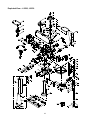
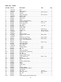
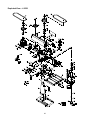
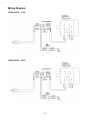
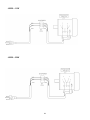
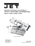
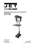
1
This .pdf document is bookmarked
Operating Instructions and Parts Manual
Drill Press
Models: J-2500, J-2530, J-2550
J-2530
WALTER MEIER (Manufacturing), Inc.
427 New Sanford Road
LaVergne, Tennessee 37086
Ph.: 800-274-6848
www.waltermeier.com
J-2500
J-2550
Part No. M-354400
Revision B 04/2012
Copyright © 2012 Walter Meier (Manufacturing), Inc.
Warranty and Service
Walter Meier (Manufacturing), Inc., warrants every product it sells. If one of our tools needs service or repair, one of our Authorized
Service Centers located throughout the United States can give you quick service. In most cases, any of these Walter Meier
Authorized Service Centers can authorize warranty repair, assist you in obtaining parts, or perform routine maintenance and major
repair on your JET® tools. For the name of an Authorized Service Center in your area call 1-800-274-6848.
Lathe Accessories
Machine Accessories
Mobile Bases
Safety Equipment
Specialty Items
Vise Accessories
Air ToolsContractor
Air Tools-Industrial
Air Tools-Light
Industrial
Lubrication
Palet Trucks
Rigging Equip.
Service Jacks
Stackers
Surface Grinders
Tapping
Trolleys-Air
Trolleys-Electric
Web Slings
Winches-Electric
WW Benchtop
Tools
5
YEAR
WW Drill Presses
WW Dust Collectors
WW Dust Filters
WW Dust Fittings
WW Jointers
WW Lathes
WW Planers
WW Shapers
WW Sanders
WW Tablesaws
LIFE
LIFETIME
WARRANTY
3
YEAR
Beam Clamps
Chain HoistManual
Lever Hoists
Pullers-JCH Models
Scissor Lift Tables
Screw Jacks
Trolleys-Geared
Trolleys-Plain
Winches-Manual
WW Air Filtration
WW Bandsaws
WW Buffers
WARRANTY
2
YEAR
WARRANTY
1
YEAR
Body Repair Kits
Bottle Jacks
Cable Pullers
Cold Saws
Hoists-Air
Hoists-Electric
Metal forming
Mill/Drills
Milling Machines
MW Bandsaws
MW Drill Presses
MW Finishing
Equipment
MW Lathes
MW Precision Vises
WARRANTY
DAY
WARRANTY
90
WARRANTY
MORE INFORMATION
Walter Meier is consistently adding new products to the line. For complete, up-to-date product information, check with your local
Walter Meier distributor, or visit waltermeier.com.
WARRANTY
JET products carry a limited warranty which varies in duration based upon the product. (MW = Metalworking, WW = Woodworking)
Fastening Tools
Mechanics Hand Tools
Striking Tools
Vises (no -precision)
Clamps
Warranty reverts to 1 Year Warranty if woodworking (WW) products listed above are used for industrial or
educational purposes.
WHAT IS COVERED?
This warranty covers any defects in workmanship or materials subject to the exceptions stated below. Cutting tools, abrasives and
other consumables are excluded from warranty coverage.
WHO IS COVERED?
This warranty covers only the initial purchaser of the product.
WHAT IS THE PERIOD OF COVERAGE?
The general JET warranty lasts for the time period specified in the product literature of each product.
WHAT IS NOT COVERED?
Five Year Warranties do not cover woodworking (WW) products used for commercial, industrial or educational purposes.
Woodworking products with Five Year Warranties that are used for commercial, industrial or education purposes revert to a One Year
Warranty. This warranty does not cover defects due directly or indirectly to misuse, abuse, negligence or accidents, normal wear-andtear, improper repair or alterations, or lack of maintenance.
HOW TO GET SERVICE
The product or part must be returned for examination, postage prepaid, to a location designated by us. For the name of the location
nearest you, please call 1-800-274-6848.
You must provide proof of initial purchase date and an explanation of the complaint must accompany the merchandise. If our
inspection discloses a defect, we will repair or replace the product, or refund the purchase price, at our option.
We will return the repaired product or replacement at our expense unless it is determined by us that there is no defect, or that the
defect resulted from causes not within the scope of our warranty in which case we will, at your direction, dispose of or return the
product. In the event you choose to have the product returned, you will be responsible for the shipping and handling costs of the
return.
HOW STATE LAW APPLIES
This warranty gives you specific legal rights; you may also have other rights which vary from state to state.
LIMITATIONS ON THIS WARRANTY
WALTER MEIER (MANUFACTURING), INC., LIMITS ALL IMPLIED WARRANTIES TO THE PERIOD OF THE LIMITED WARRANTY
FOR EACH PRODUCT. EXCEPT AS STATED HEREIN, ANY IMPLIED WARRANTIES OR MERCHANTABILITY AND FITNESS
ARE EXCLUDED. SOME STATES DO NOT ALLOW LIMITATIONS ON HOW LONG THE IMPLIED WARRANTY LASTS, SO THE
ABOVE LIMITATION MAY NOT APPLY TO YOU.
WALTER MEIER SHALL IN NO EVENT BE LIABLE FOR DEATH, INJURIES TO PERSONS OR PROPERTY, OR FOR
INCIDENTAL, CONTINGENT, SPECIAL, OR CONSEQUENTIAL DAMAGES ARISING FROM THE USE OF OUR PRODUCTS.
SOME STATES DO NOT ALLOW THE EXCLUSION OR LIMITATION OF INCIDENTAL OR CONSEQUENTIAL DAMAGES, SO THE
ABOVE LIMITATION OR EXCLUSION MAY NOT APPLY TO YOU.
Walter Meier sells through distributors only. The specifications in Walter Meier catalogs are given as general information and are not
binding. Members of Walter Meier reserve the right to effect at any time, without prior notice, those alterations to parts, fittings, and
accessory equipment which they may deem necessary for any reason whatsoever. JET® branded products are not sold in Canada by
Walter Meier.
2
Table of Contents
Warranty and Service......................................................................................................................................2
Table of Contents ...........................................................................................................................................3
Warnings........................................................................................................................................................4
Introduction ....................................................................................................................................................6
Specifications .................................................................................................................................................6
Shipping Contents ..........................................................................................................................................7
Required Tools ...............................................................................................................................................7
Assembly .......................................................................................................................................................8
Before Assembly .........................................................................................................................................8
Column Assembly .......................................................................................................................................8
Table Bracket ..............................................................................................................................................8
Crank Handle and Table Lock Handle...........................................................................................................8
Column Lock Handle ...................................................................................................................................9
Table Installation .........................................................................................................................................9
Head Assembly ...........................................................................................................................................9
Chuck and Arbor Installation ........................................................................................................................9
Chuck and Arbor Removal ......................................................................................................................... 10
Adjustment ................................................................................................................................................... 10
Depth Stop Adjustment .............................................................................................................................. 10
Changing Spindle Speeds .......................................................................................................................... 11
Return Spring Adjustment .......................................................................................................................... 11
Work Light (J-2500 and J-2530 only) .......................................................................................................... 11
Table Tilt Adjustment ................................................................................................................................. 12
Operation ..................................................................................................................................................... 12
Installing Drills ........................................................................................................................................... 12
Positioning the Workpiece .......................................................................................................................... 12
Using the Vise ........................................................................................................................................... 12
Basic Operation......................................................................................................................................... 12
Maintenance ................................................................................................................................................ 12
Lubrication ................................................................................................................................................... 12
Electrical ...................................................................................................................................................... 13
Grounding Instructions ............................................................................................................................... 13
115 Volt Operation .................................................................................................................................... 13
230 Volt Operation .................................................................................................................................... 13
Extension Cords ........................................................................................................................................ 13
Troubleshooting ............................................................................................................................................ 14
Replacement Parts .................................................................................................................................... 15
Parts List – J-2500, J-2530 ........................................................................................................................ 15
Exploded View – J-2500, J-2530 ................................................................................................................ 18
Parts List – J-2550 .................................................................................................................................... 19
Exploded View – J-2550 ............................................................................................................................ 22
Wiring Diagram............................................................................................................................................. 23
J-2500/J-2530 – 115V ............................................................................................................................... 23
J-2500/J-2530 – 230V ............................................................................................................................... 23
J-2550 ...................................................................................................................................................... 24
The specifications in this manual are given as general information and are not binding. Walter Meier
(Manufacturing), Inc., reserves the right to effect, at any time and without prior notice, changes or alterations to
parts, fittings, and accessory equipment deemed necessary for any reason whatsoever.
3
Warnings
1. Read and understand the entire owners manual before attempting assembly or operation.
2. Read and understand the warnings posted on the machine and in this manual. Failure to comply with all of
these warnings may cause serious injury.
3. Replace the warning labels if they become obscured or removed.
4. This drill press is designed and intended for use by properly trained and experienced personnel only. If you
are not familiar with the proper and safe operation of a drill press, do not use until proper training and
knowledge have been obtained.
5. Do not use this drill press for other than its intended use. If used for other purposes, Walter Meier
(Manufacturing), Inc., disclaims any real or implied warranty and holds itself harmless from any injury that
may result from that use.
6. Always wear approved safety glasses/face shields while using this drill press. Everyday eyeglasses only have
impact resistant lenses; they are not safety glasses.
7. Before operating this drill press, remove tie, rings, watches and other jewelry, and roll sleeves up past the
elbows. Remove all loose clothing and confine long hair. Non-slip footwear or anti-skid floor strips are
recommended. Do not wear gloves.
8. Wear ear protectors (plugs or muffs) during extended periods of operation.
9. Some dust created by power sanding, sawing, grinding, drilling and other construction activities contain
chemicals known to cause cancer, birth defects or other reproductive harm. Some examples of these
chemicals are:
•
Lead from lead based paint.
•
Crystalline silica from bricks, cement and other masonry products.
•
Arsenic and chromium from chemically treated lumber.
Your risk of exposure varies, depending on how often you do this type of work. To reduce your exposure to
these chemicals, work in a well-ventilated area and work with approved safety equipment, such as face or
dust masks that are specifically designed to filter out microscopic particles.
10. Do not operate this machine while tired or under the influence of drugs, alcohol or any medication.
11. Make certain the switch is in the OFF position before connecting the machine to the power supply.
12. Make certain the machine is properly grounded.
13. Make all machine adjustments or maintenance with the machine unplugged from the power source.
14. Remove adjusting keys and wrenches. Form a habit of checking to see that keys and adjusting wrenches are
removed from the machine before turning it on.
15. Keep safety guards in place at all times when the machine is in use. If removed for maintenance purposes,
use extreme caution and replace the guards immediately.
16. Make sure the drill press is firmly secured to the floor or bench before use.
17. Check damaged parts. Before further use of the machine, a guard or other part that is damaged should be
carefully checked to determine that it will operate properly and perform its intended function. Check for
alignment of moving parts, binding of moving parts, breakage of parts, mounting and any other conditions that
may affect its operation. A guard or other part that is damaged should be properly repaired or replaced.
18. Provide for adequate space surrounding work area and non-glare, overhead lighting.
19. Keep the floor around the machine clean and free of scrap material, oil and grease.
20. Keep visitors a safe distance from the work area. Keep children away.
21. Make your workshop child proof with padlocks, master switches or by removing starter keys.
4
22. Give your work undivided attention. Looking around, carrying on a conversation and “horse-play” are careless
acts that can result in serious injury.
23. Maintain a balanced stance at all times so that you do not fall or lean against the spindle or other moving
parts. Do not overreach or use excessive force to perform any machine operation.
24. Use the right tool at the correct speed and feed rate. Do not force a tool or attachment to do a job for which it
was not designed. The right tool will do the job better and safer.
25. Use recommended accessories; improper accessories may be hazardous.
26. Maintain tools with care. Keep drill bits sharp and clean for the best and safest performance. Follow
instructions for lubricating and changing accessories.
27. Make sure the work piece is securely attached or clamped to the table. Never use your hand to hold the work
piece.
28. Turn off the machine before cleaning. Use a brush or compressed air to remove chips or debris — do not use
your hands.
29. Do not stand on the machine. Serious injury could occur if the machine tips over.
30. Never leave the machine running unattended. Turn the power off and do not leave the machine until it comes
to a complete stop.
31. Remove loose items and unnecessary work pieces from the area before starting the machine.
Familiarize yourself with the following safety notices used in this manual:
This means that if precautions are not heeded, it may result in minor injury and/or possible
machine damage.
death.
This means that if precautions are not heeded, it may result in serious injury or possibly even
- - SAVE THESE INSTRUCTIONS - -
5
Introduction
The JET 15-Inch 16-Speed Drill Presses and 20-Inch 12-Speed Drill Presses, Models J-2500, J-2530 and J-2550,
feature rugged cast iron design with ground-steel columns for drilling accuracy in metal, wood, and plastic. The
head casting features a ball bearing spindle assembly, supported by four permanently-lubricated, heavy duty ball
bearings that are mounted in an enclosed quill for extended life.
Specifications
Model
J-2500
J-2530
J-2550
Stock Number ................................................ 354400 .............................. 354401 ...............................354402
Model Type .................................................... 15-Inch Floor ..................... 15-Inch Bench....................20-Inch Floor
Drilling Capacity
Cast Iron.................................................... Up to 5/8 In. ....................... Up to 5/8 In. .......................Up to 3/4 In.
Steel .......................................................... Up to 1/2 In. ....................... Up to 1/2 In. .......................Up to 5/8 In.
Drill to Center ................................................. 15 Inches ........................... 15 Inches ...........................20 Inches
Motor
Rating ........................................................ 3/4 hp, 1-Phase ................. 3/4 hp, 1-Phase .................1 hp, 1-Phase
RPM .......................................................... 1725 .................................. 1725 ...................................1725
Voltage............................................115/230V (prewired 115V).......115/230V (prewired 115V) ......115/230V (prewired 115V)
Column Diameter ........................................... 2-7/8 In. ............................. 2-7/8 In...............................3-5/8 In.
Quill
Diameter.................................................... 1-7/8 In. ............................. 1-7/8 In...............................2-1/4 In.
Travel ........................................................ 3-1/8 In. ............................. 3-1/8 In...............................4-3/4 In.
Table
Overall ....................................................... 11-1/2 x 11-1/2 In. ............. 11-1/2 x 11-1/2 In...............18-1/2 x 16-1/2 In.
Working Surface........................................ 9-1/2 x 9-1/2 In. ................. 9-1/2 x 9-1/2 In...................15-1/2 x 13-1/2
Travel ........................................................ 24 In. ................................. 15-1/2 In.............................21-1/2 In.
Base
Size ........................................................... 11 x 19-1/2 In. ................... 10-1/2 x 18 In. ....................22-3/4 x 17-3/4 In.
Working Surface........................................ 7 x 7-1/2 ........................... 8 x 8 ...................................13 x 14-1/2
Chuck Size ..................................................... 5/8-In., Key Chuck ............. 5/8-In., Key Chuck .............5/8-In, Key Chuck
Overall Dimensions
Length ....................................................... 31 In. ................................. 31 In. ..................................33-1/2 In.
Width ......................................................... 13 In. ................................. 13 In. ..................................18-1/2 In.
Height ........................................................ 63 In. ................................. 39-1/2 In.............................67 In.
Spindle to Table (Max.) .................................. 24 In. ................................. 15-1/2 In.............................24 In.
Spindle to Column (Max.) ............................. 7-1/2 In. ............................. 7-1/2 In...............................10-1/2 In.
Spindle
To Base..................................................... 48 ...................................... 24 .......................................43-1/2
Taper......................................................... MT-2 .................................. MT-2 ..................................MT-3
Number of speeds .................................... 16 ....................................... 16 .......................................12
RPM ......................................................... 200, 290, 350, 430 ............. 200, 290, 350, 430 .............150, 260, 300,
500, 580, 640, 720
500, 580, 640, 720
440, 490, 540,
800, 870, 1440, 1630
800, 870, 1440, 1630
1150, 1550, 1840,
1820, 2380, 2540, 3630
1820, 2380, 2540, 3630 2220, 2950, 4200
Shipping Weight ............................................. 185 pounds........................ 157 pounds ........................321 pounds
6
Shipping Contents
Unpack the carton and verify that all parts listed
below are included.
Main Parts
Other Material
1 ea
1 ea
1 set
1 ea
1 ea
1 ea
Head Assembly
Table
Column and Table Bracket Assembly
Base
Required Tools
1. 17mm Box Wrench or a 6” – 8” Adjustable
Wrench
2. 15/16" wrench
Additional Parts
1.
2.
3.
4.
5.
6.
7.
8.
9.
1 set
1 pc
1 pc
1 pc
1 pc
1 pc
3 pcs
4 pcs
1 set
Owner’s Manual
Warranty Registration Card
Chuck and Chuck Key
Arbor
Drift Key
Table Crank Handle
Table Lock Handle
Column Lock Handle
Downfeed Handles and Knobs
M10 x 40 Hex Cap Screws
Hex Wrenches (3mm, 5mm, 6mm)
Additional Parts
7
2. Install the table bracket (A) together with the
rack (B) as shown in Figure 2.
Assembly
Read and understand all assembly instructions
before attempting assembly! Failure to comply
may cause serious injury!
Before Assembly
1. Remove the
container.
contents
from
the
shipping
2. Compare the contents of the shipping container
with the list found above. Report any shortages
or damage to your JET distributor.
3. Clean all rust protected surfaces with kerosene
or a light solvent. Do not use lacquer thinner,
paint thinner, or gasoline. These will damage
plastic components and painted surfaces.
Figure 2
3. Slide the rack ring (D) over the column (C),
placing it so it rests against the rack (B) as
shown in Figure 3 and tighten firmly.
Column Assembly
Referring to Figure 1:
1. Place the base (A) on a level floor.
2. Place the column assembly (B) on the base (A)
and align the holes in the column support with
the holes in the base.
3. Note: The column shown in Figure 1 is for the
JDP-15MF. While the JDP-15M column is
slightly different in appearance, the assembly
procedure is the same.
4. Using a 17mm wrench, secure the column (B)
with four M10 x 40 hex cap screws (C) to the
base.
Figure 3
Crank Handle and Table Lock Handle
Referring to Figure 4 (shown already assembled):
1. Loosen the setscrew (B) on the table crank
handle (A).
2. Slide the handle (A) onto the table bracket shaft.
3. Turn the handle until the setscrew is opposite
the flat section on the shaft, and tighten the
setscrew to secure the handle.
4.
Install the table lock handle (C), but do not tighten.
Figure 1
Table Bracket
When shipped, the rack ring and rack are bundled
together with the column in plastic wrap.
Referring to Figures 2 and 3:
1. Remove the wrap and take the rack ring (D) and
rack (B) off the column (C).
Figure 4
8
2. Rotate head assembly until sides of the pulley
cover are parallel with the sides of the base.
Column Lock Handle
Referring to Figure 5:
3. Tighten two setscrews (A) with a 5mm hex
wrench (provided) until they are snug.
Thread the column lock handle (D) into the table
bracket (E).
Figure 7
4. Install three downfeed handles (B) into the
downfeed hub (C).
Figure 5
Chuck and Arbor Installation
Table Installation
Referring to Figure 8:
Referring to Figure 6:
1. Twist the chuck (B) to retract the chuck jaws if
they are exposed.
1. Place the table (A) on the bracket (B).
2. Install the chuck (B) to the arbor (A) tightly.
2. Tighten the table lock handle (C).
3. Insert the chuck and arbor assembly into the
spindle (C). Pull the downfeed handle down to
press the arbor in place.
Note: Put a piece of scrap wood (D) on the table to
protect the chuck nose when pulling the downfeed
handle (E) down to press into place.
Figure 6
Head Assembly
Referring to Figure 7:
1. With the aid of a second person, carefully lift the
head onto the column top and slide it down into
position
Figure 8
The head assembly is heavy!
lifting onto the column!
Use care when
9
Chuck and Arbor Removal
Adjustment
Referring to Figure 9:
1. Unplug machine from the power source.
Depth Stop Adjustment
2. Raise the table until it is about seven inches
below the chuck.
Referring to Figure 10:
To drill multiple holes at the same preset depth, use
the depth stop:
3. Place a piece of scrap wood on the table, and
lower quill (A) using the downfeed handle.
1. Use a pencil to mark the depth the bit will drill
into the workpiece.
4. Rotate spindle to align the keyhole in the spindle
with the keyhole in the quill.
2. With the drill bit in the chuck, lower downfeed
handle to advance bit to your mark (A).
5. Insert the drift key (B) into the aligned slots and
tap lightly. The chuck and arbor assembly
should fall from the spindle.
3. With your other hand, advance the lock nuts (B)
on the depth stop rod until they are snug to the
seat (C).
4. The drill bit will now advance to this point.
5. To release, advance the nuts counter-clockwise
to the top of the depth stop.
Figure 9
Figure 10
10
6. Tighten two bar knobs (E, Fig. 11). Belts are
properly tensioned when finger and thumb
pressure midway between the two pulleys
causes approximately ½” deflection.
Changing Spindle Speeds
A spindle speed and pulley/belt arrangement chart
for all models is found on the inside of the pulley
cover (D, Fig. 11). Refer to this chart whenever
changing speeds.
Note: The chart in Figure 12 is for models J-2500
and J-2530 only.
To change spindle speeds:
1. Unplug the machine from the power source.
2. Loosen two bar knobs (E, Fig. 11) found on
each side of the head assembly.
3. Rotate the tension adjuster (F, Fig. 11)
clockwise to bring the motor base as close to the
head as possible.
4. For desired speed, change the location of belts
per pulley/belt arrangement chart.
5. Rotate the tension adjuster (F. Fig.
counterclockwise to tension the belts.
Figure 11
11)
Figure 12 – Spindle Speed Chart for J-2500, J-2530
Return Spring Adjustment
The return spring is adjusted at the factory and
should not need further adjustment. If adjustment is
deemed necessary, follow the steps below while
referring to Figure 13:
1. Unplug the machine from the power source.
2. Loosen two hex nuts (A). Do not remove.
3. Firmly hold the coil spring cover (B).
4.
5.
Pull out the cover and rotate until the pin (C) on
the return spring plate engages the next notch in
the coil spring cover. Turn the cover clockwise to
decrease tension and counter-clockwise to
increase tension.
Work Light (J-2500 and J-2530 only)
Tighten two hex nuts (A). Do not over-tighten. Nuts
should not contact the housing when tight. The hex
nuts should be tightened against each other.
Install a light bulb, no larger than 60 watts into the
socket accessed from beneath the head. The rocker
switch controls the light switch (D, Fig. 13).
Figure 13
11
Table Tilt Adjustment
Positioning the Workpiece
The table tilt adjustments are made on the table
bracket under the table.
Always place a piece of wood (or plywood) on the
table. This will prevent "splintering" or making heavy
burrs on the underside of the workpiece as the drill
breaks through. The wood should contact the left
side of the column.
To tilt the table (refer to Figures 14 and 15):
Using the Vise
In the following steps do not over loosen. This
could result in the table assembly to separate
from the column, fall and cause injury.
For the small workpiece that cannot be clamped to
the table, use a drill press vise. The vise must be
clamped or bolted to the table. Always use a backup piece of scrap wood to cover the table. This
protects both the table and the drill bit.
1. Loosen the socket head set screw (A) with a
3mm hex wrench.
2. Using a 15/16" wrench, loosen the hex cap
screw (B), and tilt the table to the desired angle
by aligning the arrow (C, Fig. 15) on the rotating
part of the bracket to the desired angle (in
degrees) displayed on the scale (D, Fig 15) at
the base of the bracket.
Basic Operation
Place material to be drilled in such as way as to
come into contact with the left side of the column.
This prevents the material from spinning.
3. Tighten the hex cap screw (B).
4. Tighten the socket head set screw (A).
If the work piece is not large enough to come
into contact with the column, use a clamp or drill
press vise that is securely fastened to the table!
Failure to comply may cause serious injury!
Feed the bit into the material with only enough force to
allow the drill bit to work. Feeding too slowly may cause
burning of the workpiece. Feeding too quickly may
cause the motor to stop and/or the drill bit to break.
Generally speaking, the smaller the drill bit, the greater
the RPM required. Wood requires higher speeds than
metal. Metal is usually drilled at slower speeds.
In dusty environments, frequently blow out any dust
that accumulates inside the motor.
Figure 14
Maintenance
Before any intervention on the machine,
disconnect it from the electrical supply by
pulling out the plug or switching off the main
switch! Failure to comply may cause serious
injury.
A coat of automobile-type wax applied to the table
and column will help to keep the surfaces clean.
Figure 15
Operation
If the power cord is worn, cut, or damaged in any
way, have it replaced immediately.
Installing Drills
Lubrication
Insert the drill into the chuck jaws about 1" (25.4mm)
long. When using a small drill do not insert it so far
that the jaws touch the flutes of the drill. Make sure
that the drill is centered in the chuck before
tightening the chuck with the key.
All of the ball bearings are packed with grease at the
factory. They require no further lubrication.
Periodically lubricate the gear, rack, table elevation
mechanism, the splines (grooves) in the spindle, and
the teeth of the quill with a #2 tube grease.
12
Electrical
230 Volt Operation
Grounding Instructions
Referring to Figure 17:
If 230V, single-phase operation is desired, the following
instructions must be followed:
This tool must be grounded while in use to protect
the operator from electric shock.
Disconnect the machine from the power source.
The JET drill press motor has four numbered leads that
are factory connected for 115V operation, as shown in (A).
For 230V operation reconnect the leads as shown in (B).
In the event of a malfunction or breakdown, grounding
provides a path of least resistance for electric current to
reduce the risk of electric shock. This tool is equipped with
an electric cord having an equipment-grounding conductor
and a grounding plug. The plug must be plugged into a
matching outlet that is properly installed and grounded in
accordance with all local codes and ordinances.
The 115V attachment plug (C), supplied with the drill
press, must be replaced with a UL/CSA listed plug
suitable for 230V operation (D). Contact your local
Authorized JET Service Center or qualified electrician
for proper procedures to install the plug. The drill press
must comply with all local and national codes after the
230-volt plug is installed.
Do not modify the plug provided. If it will not fit the outlet,
have the proper outlet installed by a qualified electrician.
Improper connection of the equipment-grounding
conductor can result in a risk of electric shock. The
conductor, with insulation having an outer surface that is
green with or without yellow stripes, is the equipmentgrounding conductor. If repair or replacement of the
electric cord or plug is necessary, do not connect the
equipment-grounding conductor to a live terminal.
The drill press with a 230-volt plug should only be
connected to an outlet having the same configuration as
shown in (D). No adapter is available nor should be used
with the 230-volt plug.
Check with a qualified electrician or service personnel if
the grounding instructions are not completely
understood, or if in doubt as to whether the tool is
properly grounded. Use only three wire extension cords
that have three-prong grounding plugs and three-pole
receptacles that accept the tool’s plug.
Repair or replace a damaged or worn cord immediately.
115 Volt Operation
Referring to Figure 16:
As received from the factory, your drill press is ready to
run at 115-volt operation. This drill press, when wired for
115 volt, is intended for use on a circuit that has an
outlet and a plug that looks like the one illustrated in (A).
A temporary adapter, which looks like the adapter shown
in (B), may be used to connect this plug to a two-pole
receptacle if a properly grounded outlet is not available.
The temporary adapter should only be used until a
properly grounded outlet can be installed by a qualified
electrician. This adapter is not applicable in Canada. The
green colored rigid ear, lug, or tab, extending from the
adapter, must be connected to a permanent ground such
as a properly grounded outlet box.
Figure 17
Extension Cords
Make sure your extension cord is in good condition.
When using an extension cord, be sure to use one
heavy enough to carry the current your machine will
draw. An undersized cord will cause a drop in the line
voltage resulting in power loss and overheating. The
table following shows the correct size to use depending
on the cord length and nameplate ampere rating. If in
doubt, use the next heavier gauge. Remember, the
smaller the gauge number, the heavier the cord.
Length of Cord
000 – 25 Feet
025 – 50 Feet
AWG
16
14
The drill press with a 230-volt plug should only be
connected to an outlet having the same configuration
(D, Fig. 17). No adapter is available or should be used
with the 230-volt plug.
Figure 16
Important: In all cases (115 or 230 volts), make certain the
receptacle in question is properly grounded. If you are not
sure, have a registered electrician check the receptacle.
13
Troubleshooting
Trouble
Drill press will not start.
Drill press does not
come up to speed.
Drill Press vibrates
excessively.
Noisy Operation.
Workpiece Burns.
Drill bit wanders.
Wood splinters on the
underside.
Drill bit binds in
workpiece.
Excessive drill bit
runout, or wobble.
Probable Cause
Remedy
Drill press unplugged from wall, or motor.
Check all plug connections.
Fuse blown, or circuit breaker tripped.
Replace fuse, or reset circuit breaker.
Cord damaged.
Replace cord.
Starting capacitor bad.
Replace starting capacitor.
Extension cord too light or too long.
Replace with adequate size and length cord.
Low current.
Contact a qualified electrician.
Stand on uneven surface.
Adjust stand so that it rests evenly on the floor.
Bad belt(s).
Replace belts.
Incorrect belt tension.
Adjust belt tension. See the Changing Spindle
Speeds section.
Dry spindle.
Lubricate spindle. See the Lubrication section.
Loose spindle pulley.
Check tightness of retaining nut on pulley, and tighten
if necessary.
Loose motor pulley.
Tighten setscrews in pulleys.
Incorrect Speed.
Change to appropriate speed; see the Changing
Spindle Speeds section.
Chips not clearing from hole or bit.
Retract drill bit frequently to remove chips.
Dull drill bit.
Resharpen, or replace drill bit.
Feeding too slowly.
Increase feed rate.
Bit sharpened incorrectly.
Resharpen bit correctly.
Bent drill bit.
Replace drill bit.
Bit, or chuck not installed properly.
Reinstall the chuck, or bit properly.
No backing board used.
Place a scrap board underneath the workpiece to
prevent splintering.
Workpiece pinching the bit.
Support or clamp workpiece.
Excessive feed rate.
Decrease feed rate.
Chuck jaws not tight.
Tighten chuck jaws.
Improper belt tension.
Adjust belt tension (Changing Spindle Speeds )
Bent drill bit.
Replace drill bit.
Worn spindle bearings.
Replace spindle bearings.
Bit, or chuck not properly installed.
Reinstall the bit, or chuck properly.
Quill returns too slow, or
Spring has improper tension.
too fast.
Adjust spring tension. See the Return Spring
Adjustment section.
Chuck or arbor does not Dirt, grease, etc on arbor, chuck, or
stay in place.
spindle.
Clean all mating surfaces thoroughly with a cleaner
degreaser.
14
Parts
Replacement Parts
To order parts or reach our service department, call 1-800-274-6848 Monday through Friday (see our website for
business hours, www.waltermeier.com). Having the Model Number and Serial Number of your machine available
when you call will allow us to serve you quickly and accurately.
Parts List – J-2500, J-2530
Index No. Part No.
Description
Size
Qty
1A............ 10600110 ................Base for J-2530 / JDP-15M ................................................................. 1
1B............ 10800101 ................Base for J-2500 / JDP-15MF (not shown) ............................................. 1
2A............ JDP15-1002A ..........Column Holder for J-2530 / JDP-15M................................................... 1
2B............ 10600204 ................Column Holder for J-2500 / JDP-15MF................................................. 1
3 .............. TS-2279121 ............Hex Socket Set Screw ......................................M10-12 ...................... 3
4A............ JDP15-1004A ..........Body Column for J-2530 / JDP-15M ..................................................... 1
4B............ JDP15-1004B ..........Body Column for J-2500 / JDP-15MF ................................................... 1
................ 10600404A1 ............Column Assy for J-2530 / JDP-15M (includes #2A and #4A) .................. 1
................ 10400401A1 ............Column Assy for J-2500 / JDP-15MF (includes #2B, #3 and #4B) .......... 1
5 .............. TS-2229403 ............Hex Head Bolt ..................................................M10x40 ...................... 4
6 .............. 10600604 ................Table Bracket ..................................................................................... 1
................ JDP15-1006 ............Table Bracket Assy (includes #6 thru #18) ............................................ 1
7 .............. 10600702 ................Gear .................................................................................................. 1
8 .............. 10600802 ................Gear Shaft ......................................................................................... 1
9 .............. 10600902 ................Worm................................................................................................. 1
10A.......... 10601009A1 ............Crank Handle Assy ............................................................................. 1
12 ............ JDP15-1012 ............Table Bracket ..................................................................................... 1
13 ............ TS-0071011 ............Hex Head Bolt ..................................................5/8-11 x 1-1/2 ............. 1
14 ............ TS-2276101 ............Hex Socket Set Screw ......................................M6-10 ........................ 1
16 ............ 10601601 ................Tilting Scale ....................................................................................... 1
17 ............ JDP15-1017 ............Centering Scale .................................................................................. 1
18 ............ JDP15-1018 ............Drive Screw......................................................Φ 2.3-5 ...................... 2
19 ............ 10601901 ................Column Lock Handle.........................................M12 x 1.75-35 ........... 1
20 ............ 10602001 ................Table Lock Handle ............................................M10 x 1.5 .................. 1
21 ............ J-5625221 ...............Table ................................................................................................. 1
22A.......... 10602204 ................Rack for J-2530 / JDP-15M ................................................................. 1
22B.......... 10602205 ................Rack for J-2500 / JDP-15MF ............................................................... 1
23 ............ 10602304 ................Rack Ring ........................................................Φ 73.5........................ 1
24 ............ TS-2276081 ............Hex Socket Set Screw ......................................M6-8 .......................... 1
25 ............ JDP15-1025 ............Head.................................................................................................. 1
26 ............ TS-2279121 ............Hex Socket Set Screw ......................................M10-12 ...................... 2
27 ............ JDP15-1027 ............Lamp Socket ...................................................................................... 1
28 ............ TS-1534042 ............Cr. Re. Pan Head Screw ...................................M6-12 ........................ 2
29 ............ 10602901 ................Handle Shifter .................................................................................... 1
30 ............ 10603002 ................Motor Bar Shifter ................................................................................ 1
31 ............ TS-2228161 ............Hex Head Bolt ..................................................M8-16 ........................ 1
32 ............ 10603206 ................Motor Rod .......................................................................................... 1
33 ............ 10603301 ................Shifter Bolt .......................................................M10-33 ...................... 2
34 ............ 10603416 ................Motor Base.......................................................75 x 125mm ............... 1
35 ............ 2502NBC412 ...........Spring Washer..................................................Φ1/2" ......................... 1
36 ............ TS-1540081 ............Hex Nut............................................................M12 ........................... 2
37 ............ 10603704 ................Hub ................................................................................................... 1
38 ............ 10603807 ................Feed Shaft ......................................................................................... 1
................ JDP15-1038 ............Feed Shaft Assy (includes #37 thru #39) .............................................. 1
39 ............ TS-209402 ..............Roll Pin ............................................................M5-16 ........................ 1
43A.......... JDP15-1043 ............Handle Bar ......................................................................................... 1
15
Parts List – J-2500, J-2530
Index No. Part No.
Description
Size
Qty
45 ............ 10604505 ................Scale Ring ......................................................................................... 1
50A.......... JDP15-1050 ............Spring Cap ......................................................................................... 1
51 ............ 10605115 ................Shaft Seat .......................................................................................... 1
53 ............ TS-0561052 ............Hex Nut............................................................1/2"-20 ....................... 1
54 ............ 10605403 ................Quill Set Screw .................................................M10-28 ...................... 1
55 ............ TS-1540071 ............Hex Nut............................................................M10 ........................... 1
56 ............ 10605608 ................Quill .................................................................MT2 ........................... 1
................ JDP15-1056 ............Quill and Spindle Assy (includes #56 thru # 64) .................................... 1
57 ............ 10605702 ................Rubber Washer .................................................................................. 1
58 ............ 10605822 ................Spindle ............................................................MT2 ........................... 1
59 ............ 2001ZZ6204 ............Ball Bearing........................................................................................ 1
61 ............ 2001ZZ6203 ............Ball Bearing........................................................................................ 1
62 ............ TS-2360161 ............Washer ............................................................M16 ........................... 1
63 ............ 10606301 ................Nut Lock ............................................................................................ 1
64 ............ 10606401 ................Spindle Nut ........................................................................................ 1
65 ............ 10606505 ................Driving Sleeve .................................................................................... 1
................ JDP15-1065 ............Driving Sleeve Assy (includes #65 thru #67) ......................................... 1
66 ............ 2001ZZ6204 ............Ball Bearing........................................................................................ 2
67 ............ 10606703 ................Rack ring..........................................................Φ 45 T=4.................... 1
68 ............ 10606801 ................Retaining Ring .................................................................................... 2
69 ............ 10606904 ................Pulley Set Nut .................................................................................... 1
70 ............ JDP15-1070 ............Spindle Pulley .................................................................................... 1
71 ............ 21015M2J30 ...........Drilling Arbor ....................................................MT2*JT3 .................... 1
72A.......... JDP15-1072 ............Chuck Assy ........................................................................................ 1
73 ............ 10607303 ................Wedge Shifter .................................................................................... 1
74 ............ JDP15-1074 ............Motor ................................................................................................. 1
................ JDP15-1074A ..........Centrifugal Switch (not shown) ............................................................ 1
................ JDP15-1074B ..........Start Capacitor (not shown) ...............................200MFD 125VAC ....... 1
75 ............ JDP15-1075 ............Motor Wire ......................................................................................... 1
76 ............ TS-2208201 ............Hex. Hd. Screw ................................................M8-20 ........................ 4
77 ............ TS-1550061 ............Flat Washer......................................................M8 ............................. 8
78 ............ TS-1540061 ............Hex Nut............................................................M8 ............................. 4
79 ............ JDP15-1079 ............Motor Pulley ....................................................................................... 1
80 ............ 2571MNC307 ..........Parallel Key ......................................................5 x 5-20...................... 1
81 ............ TS-1504021 ............Hex Socket Set Screw ......................................M8-12 ........................ 1
83 ............ JDP15-1083 ............Strain Relief ....................................................................................... 1
84 ............ TS-1534042 ............Cr. Re. Pan Head Screw ...................................M6-12 ........................ 1
85 ............ JDP15-1085 ............Power Cable ...................................................................................... 1
87 ............ JDP15-1087 ............Rocker Switch .................................................................................... 1
88 ............ JDP15-1088 ............Switch Box ......................................................................................... 1
89 ............ TS-1533042 ............Cr. Re. Pan Head Screw ...................................M5-12 ........................ 3
90A.......... JDP15-1090 ............Pulley Cover Assy............................................................................... 1
................ JDP15-1090A ..........U Shaped Protecting Rubber (not shown)............................................. 1
92 ............ JDP15-1092 ............Cr. Re. Round Washer Hd. Screw......................M6 x 1.0-12 ................ 4
95 ............ JDP15-1095 ............Center Pulley...................................................................................... 1
................ JDP15-1095A ..........Center Pulley Assy (includes #95 thru #98) .......................................... 1
96 ............ JDP15-1096 ............Ball Bearing........................................................................................ 2
98 ............ 10609801 ................Center Pulley Shaft ............................................................................. 1
99 ............ VB-A28 ...................V-Belt...............................................................A-28........................... 1
101 .......... TS-0680021 ............Flat Washer......................................................1/4" ............................ 4
106 .......... TS-0561052 ............Hex Nut............................................................½”-20 ......................... 1
109 .......... JDP15-1109 ............Clamp-Cord........................................................................................ 3
110 .......... 2668BBDA23...........Cr. Re. Pan Head Screw ..................................M5-8 .......................... 3
112 .......... 10611201 ................Chuck Key Holder ............................................................................... 1
113 .......... TS-2286122 ............Cr. Re. Round Washer Hd. Screw......................M6-12 ........................ 1
119 .......... VB-A26 ...................V-Belt...............................................................A-26........................... 1
16
Parts List – J-2500, J-2530
Index No. Part No.
Description
Size
Qty
128 .......... TS-2285162 ............Cr. Re. Truss Hd. Tapping Screw ......................M5-16 ....................... 2
137 .......... JDP15-1137 ............Switch Cover ...................................................................................... 1
138 .......... TS-1533042 ............Cr. Re. Pan Head Screw ...................................M5-12 ....................... 2
139 .......... JDP15-1139 ............Rocker Switch .................................................................................... 1
140 .......... 10614001 ................Motor Rod .......................................................................................... 1
149 .......... 2536MBE616...........Roll Pin ............................................................6-25 ........................... 2
162 .......... 10916202 ................Warning Label .................................................................................... 1
166 .......... JDP15-1166 ............Speed Diagram .................................................................................. 1
169 .......... JDP15-1169 ............Trade-Mark Label ............................................................................... 1
170 .......... 2658MZDU36 ..........Drive Screw......................................................Φ 2.3-5 ...................... 6
601 .......... TS-2245082 ............Cr. Re. Pan Head Screw ...................................M5-8 .......................... 4
602 .......... TS-0733031 ............External Tooth Lock Washer..............................No 10 ......................... 2
610 .......... TS-1534692 ............Cr. Re. Pan Head Screw ...................................M6-35 ....................... 2
611 .......... JDP15-1611 ............Cr. Re. Pan Head Screw ..................................................................... 1
612 .......... TS-1540071 ............Hex Nut............................................................M10 ........................... 1
613 .......... 10661301 ................Set Bolt .............................................................................................. 1
................ JDP15-1613 ............Set Bolt Assy (includes #613, 848, 849) ............................................... 1
614 .......... 13005701 ................Nut………………………………………….M16........................................ 2
615 .......... 13005601 ................Washer ............................................................Φ24 ........................... 1
616 .......... TS-1502081 ............Hex. Soc. Hd. Cap Blot .....................................M5-35 ....................... 1
617 .......... JDP15-1617 ............Set Ring ............................................................................................. 1
618 .......... 10661801 ................Circular Nut ........................................................................................ 1
634 .......... 2502ABC410 ...........Spring Washer..................................................Φ10 ........................... 1
700 .......... TS-152704 ..............Wrench Hex ....................................................................................... 1
701 .......... TS-152706 ..............Wrench Hex ....................................................................................... 1
702 .......... TS-152707 ..............Wrench Hex ....................................................................................... 1
801 .......... JDP15-1801 ............Lead Wire Assembly ........................................................................... 1
848 .......... JDP15-1848 ............Drive Screw......................................................Φ 2.3-5 ...................... 2
849 .......... JDP15-1849 ............Scale ................................................................................................. 1
922 .......... 2801ABRF04 ...........Strain Relief .....................................................Φ 20 .......................... 2
999 .......... TS-1540081 ............Hex Nut............................................................M12x10 ...................... 3
1000 ........ 100633Y8................Plastic Sleeve................................................. ................................... 1
1001 ........ 10810401A1 ............Chuck Guard Assembly................................... ................................... 1
17
Exploded View – J-2500, J-2530
18
Parts List – J-2550
Index No. Part No.
Description
Size
Qty
1 .............. J-5627751 ...............Base .................................................................................................. 1
2 .............. J-5627761 ...............Collar, Column.................................................................................... 1
3 .............. 5626231 ..................Set Screw ........................................................M10 x 40 mm ............. 1
4 .............. 5627771 ..................Column .............................................................................................. 1
5 .............. 5627781 ..................Screw, Hex Head..............................................M12 x 40 mm ............. 4
6 .............. J-5627791 ...............Bracket, Table .................................................................................... 1
7 .............. 5625071 ..................Gear, Pinion ....................................................................................... 1
8 .............. 5625081 ..................Shaft, Gear......................................................................................... 1
9 .............. 5625091 ..................Worm................................................................................................. 1
10 ............ 5627811 ..................Handle, Lowering/Raising.................................................................... 1
11 ............ 5626251 ..................Screw, Hex Head..............................................M6 x 12 mm ............... 1
13 ............ 5627821 ..................Screw, Hex Head..............................................5/8” x 2” ..................... 1
14 ............ 5627831 ..................Pin, Location ...................................................................................... 1
15 ............ 5627841 ..................Nut, Hex...........................................................1/4" x 20” ................... 1
16 ............ 5627851 ..................Scale, Tilting....................................................................................... 1
17 ............ 5625181 ..................Scale, Angle ....................................................................................... 1
18 ............ 5625191 ..................Set Screw ........................................................Ø2.3x 5 mm ............... 3
19 ............ 5625211 ..................Handle, Lock ....................................................M12 x 180 mm............ 1
21 ............ J-5627861 ...............Table ...............................................................18-3/4” x 16-3/4” ......... 1
22 ............ 5627871 ..................Rack .................................................................................................. 1
23 ............ J-5627881 ...............Retainer, Rack.................................................................................... 1
24 ............ 5627061 ..................Screw Set, Hex Socket .....................................M6 x 10mm ................ 1
25 ............ J-5627891 ...............Head.................................................................................................. 1
26 ............ 5627021 ..................Screw Set, Hex Socket .....................................M10 x 12mm .............. 2
28 ............ 5627911 ..................Screw, Pan Head, Cr.-Re. .................................M6 x 12mm ................ 2
29 ............ 5627121 ..................Lever, Tension Adjustment .................................................................. 1
30 ............ 5627131 ..................Cam................................................................................................... 1
31 ............ 5627141 ..................Screw, Hex Head..............................................M8 x 16 mm ............... 1
32 ............ 5627921 ..................Shaft, Motor Base ............................................................................... 1
33 ............ 5627931 ..................Lock, Motor Bar .................................................................................. 2
34 ............ J-5627941 ...............Base, Motor........................................................................................ 1
35 ............ 5627181 ..................Washer, Spring.................................................Ø1/2” ......................... 2
36 ............ 5627191 ..................Nut, Hex...........................................................M12 ........................... 2
37 ............ 5627211 ..................Hub ................................................................................................... 1
38 ............ 5627951 ..................Shaft, Feed Pinion .............................................................................. 1
38A.......... 5627961 ..................Shaft Assembly, Feed Pinion ............................................................... 1
39 ............ 5627971 ..................Pin, Roll ............................................................................................. 1
40 ............ 5627241 ..................Pin, Scale Set..................................................................................... 1
41 ............ 5627981 ..................Wedge, Scale Locking ........................................................................ 1
42 ............ 5627991 ..................Screw, Depth Lock............................................M8 x 17 mm ............... 1
43 ............ 5629011 ..................Handle ............................................................................................... 3
43A.......... 5629021 ..................Bar Assembly, Handle......................................................................... 3
44 ............ 5627271 ..................Grip ................................................................................................... 3
45 ............ 5629031 ..................Housing, Spindle Depth....................................................................... 1
46 ............ 5629041 ..................Scale ................................................................................................. 1
47 ............ 5625481 ..................Pointer ............................................................................................... 1
48 ............ 5626551 ..................Screw, Drive ....................................................................................... 3
49 ............ 5629051 ..................Coil .................................................................................................... 1
50 ............ 5629061 ..................Housing, Spring .................................................................................. 1
50A.......... 5629071 ..................Housing Assembly, Spring .................................................................. 1
51 ............ 5629081 ..................Seat, Spring ....................................................................................... 1
53 ............ 5629091 ..................Nut, Hex...........................................................1/2"-20 ....................... 2
54 ............ 5627321 ..................Screw, Set, Quill ...............................................M10 x 27mm .............. 1
55 ............ 5627331 ..................Nut, Hex...........................................................M10 ........................... 1
56 ............ 5629111 ..................Quill ................................................................................................... 1
56A.......... 5629121 ..................Quill Assembly (includes #56 thru 64) .................................................. 1
19
Parts List – J-2550
Index No. Part No.
Description
Size
Qty
57 ............ 5629131 ..................Washer, Rubber ................................................................................. 1
58 ............ 5629141 ..................Spindle ............................................................MT3, Ø34................... 1
59 ............ 5629151 ..................Bearing, Ball .....................................................6206ZZ ...................... 1
60 ............ 5629161 ..................Bearing, Ball, Thrust .........................................2906 ............................
61 ............ 5635271 ..................Bearing, Ball .....................................................6204Z ........................ 1
62 ............ 5629171 ..................Washer .............................................................................................. 1
63 ............ 5629181 ..................Lock, Washer ..................................................................................... 1
64 ............ 5629191 ..................Lock, Nut............................................................................................ 1
65 ............ 5629211 ..................Lock, Driving ...................................................................................... 1
66 ............ 5629221 ..................Bearing, Ball .....................................................6206Z ........................ 2
67 ............ 5629231 ..................Collar ................................................................................................. 1
68 ............ 5629241 ..................Ring, Retaining ................................................................................... 2
69 ............ 5629251 ..................Nut, Pulley Lock ................................................................................. 1
70 ............ 5629261 ..................Pulley, Spindle.................................................................................... 1
71 ............ 5624641 ..................Arbor ...............................................................MT3 x JT3 .................. 1
72 ............ 5628931 ..................Chuck ..............................................................RJ3 - 16L .................. 1
72A.......... 5627401 ..................Chuck and Key ................................................................................... 1
73 ............ 5624671 ..................Wedge, Taper .................................................................................... 1
74 ............ J-5629271 ...............Motor ................................................................................................. 1
76 ............ 5629291 ..................Screw, Hex Head..............................................M8 x 25 mm ............... 4
77 ............ 5627511 ..................Washer, Flat ....................................................5/16” .......................... 4
78 ............ 5625821 ..................Nut, Hex...........................................................M8 ............................. 4
79 ............ 5629311 ..................Pulley, Motor ...................................................................................... 1
80 ............ 5629321 ..................Key .................................................................................................... 1
81 ............ 5629331 ..................Screw, Set .......................................................M8 x 8 mm ................. 1
83 ............ 5627551 ..................Clamp ................................................................................................ 2
84 ............ 5626841 ..................Screw, Pan Head..............................................M5 x 8 mm ................. 2
85 ............ 5629341 ..................Cord, Power ....................................................................................... 1
87 ............ JDP15-1087 ............Push-Button Switch ............................................................................ 1
88 ............ 5629361 ..................Cover, Switch ..................................................................................... 1
89 ............ 5626871 ..................Screw, Pan Head..............................................M5 x 12 mm ............... 2
92 ............ 5627591 ..................Washer, Round Head Screw .............................M6 x 12 mm ............... 4
93 ............ 5629381 ..................Screw, Truss Head Tapping ..............................M4 x 12 mm ............... 1
94 ............ 5627611 ..................Knob .................................................................................................. 1
95 ............ 5629391 ..................Pulley, Center..................................................................................... 1
96 ............ 5621681 ..................Bearing, Ball .....................................................6202Z ........................ 2
98 ............ 5629411 ..................Shaft, Pulley ....................................................................................... 1
99 ............ 5624701 ..................V-Belt...............................................................A-30........................... 1
101 .......... 5627641 ..................Washer, Flat .....................................................1/4" ............................ 4
119 .......... 5637541 ..................V-Belt...............................................................A-32........................... 1
128 .......... TS-2285162 ............Screw, Machine ................................................M5 x 16 mm ............... 2
129 .......... 5629421 ..................Screw, Socket Head Cap ..................................M8 x 30 mm ............... 2
130 .......... 5629431 ..................Screw, Socket Head Cap ..................................M8 x 25 mm ............... 1
131 .......... 5629441 ..................Key, Chuck......................................................................................... 1
140 .......... 5629451 ..................Shaft, Motor Base ............................................................................... 1
149 .......... 5629461 ..................Pin, Roll ............................................................................................. 2
601 .......... 5629471 ..................Screw, Pan Head..............................................M4 x 12 mm ............... 1
602 .......... 5629481 ..................Washer, External Tooth Lock.............................Ø4 ............................. 2
605 .......... 5629491 ..................Pin, Roll ............................................................................................. 1
606 .......... 5629511 ..................Pin, Roll ...........................................................Ø2.5 x 10 mm............. 1
610 .......... 5513738 ..................Screw ................................................................................................ 2
611 .......... 5513739 ..................Block, Depth Stop ............................................................................... 1
612 .......... 5513740 ..................Nut .................................................................................................... 1
613 .......... 5513741 ..................Rod, Depth Stop Adjustment .............................2550 Only .................. 1
614 .......... 5513742 ..................Nut, Adjustment Lock .......................................................................... 1
615 .......... 5513743 ..................Washer .............................................................................................. 1
20
Parts List – J-2550
Index No. Part No.
Description
Size
Qty
616 .......... 5513744 ..................Screw, Clamping ................................................................................ 1
617 .......... J-5518233 ...............Clamp, Depth Stop support ................................................................. 1
618 .......... 5513746 ..................Nut .................................................................................................... 1
700 .......... 5627711 ..................Wrench, Allen ...................................................3 mm ......................... 1
701 .......... 5629521 ..................Wrench, Allen ...................................................5 mm ......................... 1
903 .......... 5627721 ..................Grommet ............................................................................................ 2
904 .......... J-5629371 ...............Cover Assembly, Pulley ...................................................................... 1
905 .......... 10810402A1 ............Chuck Guard Assembly....................................................................... 1
906 .......... 11361702 ................Set Ring ............................................................................................. 1
21
Exploded View – J-2550
22
Wiring Diagram
J-2500/J-2530 – 115V
J-2500/J-2530 – 230V
23
J-2550 – 115V
J-2550 – 230V
24