1
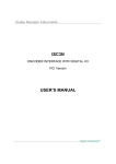
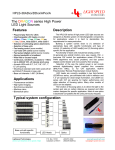
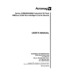
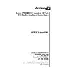
Gurley Model V860H
â
Virtual Absolute Encoder
Motion Type:
Rotary
Usage Grade:
Metrology/Industrial
Output:
Absolute
Max Resolution*:
2
20
(1,048,576) steps/rev
ingenuity@work
Ò
Natural Binary Absolute Output
The V860H is a high-performance optical encoder that utilizes unique Virtual Absolute
technology to combine the opto-mechanical simplicity and ruggedness of an
incremental encoder with the system reliability and interfacing ease of an absolute
encoder.
This encoder has been designed for quasi-military applications such as radar pedestals
and tracking mounts.
* Custom resolutions available up to 24 bits. Please contact factory for more information
ISO
9001
Certified
Gurley Precision Instruments
514 Fulton Street
Troy, NY 12180 U.S.A.
(800) 759-1844, (518) 272-6300, fax (518) 274-0336,
Online at www.gurley.com, e-mail: [email protected]
GPI
IIIIIIIIIIIIII
SPECIFICATIONS
20
*Resolution
2 (1,048,576) words/rev
** Installed Accuracy
±1.5 arcs, including quantization & coupling errors
Initialization angle
0.308°
Output code
Parallel natural binary
Output device
TTL-compatible tri-state buffer registers
Max. data update rate
1 MHz
Parity
Odd
Shaft direction for increasing count
Clockwise, looking at bellows end
Input power
+12Vdc ±0.5V @375 mA max
Illumination source
LEDs, screened and derated for 100,000-hr life
Max. operating speed
120°/s
Operating temperature, °F (°C)
-40 to +185 (-40 to +85)
Storage temperature, °F (°C)
-58 to 212 (-50 to + 100)
Humidty
98% rh, non-condensing
Weight, encoder + coupling lb (kg)
12 lb (5.5)
** Starting torque, in-oz (N-m)
16 (0.11)
** Running torque, in-oz (N-m)
12 (0.08)
2
3
Moment of inertia, in-oz-s (g-cm)
0.27 (19 x 10 )
Sealing
IP64
* Custom resolutions available up to 24 bits. Please contact factory for more information.
** At 20°C
As part of our continuing product improvement program, all specifications are subject to change without notice.
V860H
Page 2 of 8
V3.1
Gurley Precision Instruments
514 Fulton Street
Troy, NY 12180 U.S.A.
(800) 759-1844, (518) 272-6300, fax (518) 274-0336,
Online at www.gurley.com, e-mail: [email protected]
GPI
IIIIIIIIIIIIII
Theory of Operation
A Gurley Virtual Absolute (VA) encoder employs an optical encoding technique which is still relatively new to the
motion control industry. Like an incremental encoder, the VA optical disc uses only incremental and index code tracks.
The incremental track is structured and read by quadrature sensors in the usual way. However, neither the encoder nor
the host system accumulate incremental counts as the read station traverses. Instead, the four quadrature states per
optical cycle are decoded to control the spatial timing of indexing operations, whereby the absolute position information
is obtained. The index track is coded differently from a conventional incremental encoder. On the index track, an
opaque or transparent region exactly one optical cycle wide aligns correspondingly with every opaque/transparent line
pair in the adjacent incremental track. Around the full circumference of the disc, any given index mark is equally likely to
be clear or opaque. The bit sequence into which the index marks will be translated by the detector dedicated to this
track is pseudorandom. Absolute position is encoded serially in this one track rather than in parallel over many tracks.
This simplifies optomechanical alignment compared with traditional absolute encoders.
A 14-bit VA employs a sequence of 16384 indices. These are decoded for cycle position, to which 6 bits of interpolated
position within the cycle are appended. Every possible grouping of 14 consecutive indices in the sequence is unique
due to the non-repeating design of the code. Every optical cycle of the incremental timing track is thus tagged by a
unique 14-bit code whose first bit is immediately adjacent to the cycle, and whose remaining 13 bits trail behind. This
arrangement is sometimes called a chain code. Because the coding sequence is such that each 14-bit code tag shares
13 bits with its neighboring tags to the left and right, in overlapping fashion, one might conclude that the code
progression is monostrophic (like Gray code) with only one bit differing between consecutive tags. Not so. While
adjacent tags share all but one bit, the positions of all the shared bits within the tags are shifted. Tags which truly differ
by only one bit are located in seemingly random sections of the scale. Improperly decoded tags would therefore result
in gross position errors. Partly for this reason, a sophisticated sequence verification capability is an integral part of
GPI's proprietary Virtual Absolute tag decoder design.
On power-up, absolute position is unknown. An initialization procedure is executed to obtain a complete tag for
decoding. (There are ways to build a pseudorandom encoder so that absolute information is available on power-up
without initializing, but these techniques require far more complex sensing hardware; they often impose slower
operation as well. And none of them offers the sophisticated built-in testing of GPI's Virtual Absolute technology.)
Because the index track is viewed by a single sensor the read station must be bumped in either direction, or wiggled in
both, to cover a minimum net angle. In this case, a net motion infinitesimally less than 14 optical cycles guarantees 14
major cycle boundaries of the incremental timing track will be crossed. This corresponds to 0.308 maximum
initialization traverse from any starting position of the disc. Discs with higher line counts require shorter initialization
traverses, but are correspondingly more difficult to install and align. Cycle boundary phasing with respect to the index
marks is such that indices are sampled only at their centers, i.e., spatially timed. For this reason, the incremental track
is sometimes called the timing track. This arrangement has two important benefits:
!
As with conventional incremental encoders, the readout accuracy (linearity) of the VA encoder depends only on the
regularity of its incremental track lines. These are easy to create on the disc with precision, and easy for the
quadrature detectors to read accurately through slit gratings that average out microscopic optical printing
imperfections and moderate amounts of contamination. This also results in healthier signal amplitudes.
Conventional absolute encoders have difficulty employing a similar optical averaging technique to improve readout
accuracy and signal-to-noise ratio.
!
The serial indices, which must be viewed through a single mask aperture like a conventional absolute, rather than
through a grating, are at their maximal light or dark conditions when sampled. This ensures the greatest electrical
noise margin, immunity to contamination, and
tolerance of misalignment between disc and read station. Unlike a conventional absolute encoder, the exact
angular position of the transition between light and dark has no effect on decoding reliability or accuracy.
V860H
Page 3 of 8
V3.1
Gurley Precision Instruments
514 Fulton Street
Troy, NY 12180 U.S.A.
(800) 759-1844, (518) 272-6300, fax (518) 274-0336,
Online at www.gurley.com, e-mail: [email protected]
GPI
IIIIIIIIIIIIII
Theory of Operation
Once the first tag has been obtained from the disc, bit-wise, during the initialization traverse, ensuing motions modify the tag
based on direction of motion. (Direction sense is always available from the quadrature incremental track waveforms.) As
new tags become available, they are decoded into monotonic natural-binary absolute position words. During the tag
decoding process, an exor gate compares each new detected bit obtained from the index track against the bit the tag
decoder predicts for that direction of motion. In effect, the decoder knows the entire serial code sequence and reports any
disagreement between expected and detected tag bits as a fault condition. In this way, the encoder's design embodies a
sophisticated real-time automatic error detection technique that is constantly on guard against malfunction with every
motion of the disc. This capability is equivalent to the most fully refined monotonicity test system possible in a conventional
absolute encoder, yet imposes no appreciable overhead in hardware because it is a natural byproduct of GPI's patented tag
decoding method.
A GPI Virtual Absolute encoder system can be in any one of 3 distinct operating modes:
!
Wait mode: It may be aware of an interruption of power, or some other interference to normal operation which it
interpreted as an invalid tag. Until a (re)initialization traverse has been executed to refresh the code tag in the decoder,
the VA reports a fault condition while it is waiting for a full tag to be acquired.
!
Search mode: Having acquired a complete new tag from an initialization sweep, it may be busy pinpointing the absolute
position of the new tag in the overall code sequence. How long this tag search will take depends on specific design
characteristics of the decoder, including its 16-MHz clock speed. It also depends on how far away the read station
happens to be from the starting point of the search, and whether the decoder is chasing the axis position from behind as
it also moves during the search. In the worst case scenario, a 14 bit tag search will take about 4 mS.
!
Track mode: It may be decoding all new indexing code tags obtained from the read station satisfactorily, validating the
code bit-wise as it's detected, and providing reliable absolute position information, i.e., tracking the motion input in servo
fashion.
If scale contamination or overwhelming electrical noise should invalidate the index signal or even the proper operation of the
decoder itself, this will result in a reported fault:
!
Proper quadrature sequence is verified at all times. Since this could corrupt the tag bit due to improper sample timing,
the decoder resets and awaits a fresh tag.
!
Successors to a false tag will survive very little following motion of the disc before faulting due to the non-repeating
nature of the code sequence.
!
A supply voltage supervisor and power-up reset IC is included to reset the decoder if the power supply dips below
+4.70VDC measured locally inside the encoder.
Most fault conditions may be cleared by re-executing the initialization procedure. In the case of disc damage or fouling, the
host system may measure the affected region by approaching it from alternate directions and observing the Status bit
reporting the validity of the absolute position output.
The Status bit offers a simple mechanism for a microprocessor-based host system to quickly assess data validity. If the tag
decoder detects a fault condition and is waiting for an initial tag sweep or while it is still engaged in a tag search, the Status bit
will be set to a logic 1, signifying the current output value is invalid and position is unknown.
For a more thorough discussion, see the V860H User's Manual.
V860H
Page 4 of 8
V3.1
Gurley Precision Instruments
514 Fulton Street
Troy, NY 12180 U.S.A.
(800) 759-1844, (518) 272-6300, fax (518) 274-0336,
Online at www.gurley.com, e-mail: [email protected]
GPI
IIIIIIIIIIIIII
SPECIFICATIONS
READOUT TIMING REQUIREMENTS
The read cycle is initiated by bringing the
Interrogate line low. The data will be valid
750nS after the falling edge of INT.
Synchronicity of all data transitions cannot
be guaranteed in any device with natural
binary output. The output buffer register is
provided to avoid reading out a mixture of
old and new data bits when sampling the
output at the exact moment position data is
changing.
SHAFT COUPLING
The optional precision flexible metal bellows assembly P/N DX00432
compensates for small angular misalignment, axial extension or
compression, or parallel offset in the installation, without affecting bearing or
bellows life. Keeping the misalignments within the following constraints will
assure infinite life of the coupling, but will introduce some error. To preserve
the encoder's accuracy, misalignments should be kept as small as possible.
83.3P + 3E + 0.14A < 1.0
P = Parallel offset, inches (max = 0.012")
E = Axial extension or compression, inches (max = 0.336")
A = Angular misalignment, degrees (max = 7)
Parallel offset, P, is equal to the total offset between the centerline of the
encoder and the centerline of the user's shaft, plus half the radial runout
(TIR/2) of the user's shaft.
Table 1 - Power Pin Connections, DA-15P
Pin
1
2
3
4
5
6
7
8
9
10
11
12
13
14
15
Name
GND
GND
Type
Power
Power
Description
Ground, power supply common
Ground, power supply common
GND
GND
+12
Power
Power
Power
Ground, power supply common
Ground, power supply common
Single +12VDC supply, regulated to +5VDC internally
GND
Power
Ground, power supply common
GND
+12
+12
Power
Power
Power
Ground, power supply common
Single +12VDC supply, regulated to +5VDC internally
Single +12VDC supply, regulated to +5VDC internally
V860H
Page 5 of 8
V3.1
ELECTRICAL CONNECTIONS
If the V860H is ordered with connector code P,
the three cables are terminated in pigtails; the
wire colors are shown on the dimension
drawing on page 8. If it is ordered with
connector code D, the cables are terminated in
two connectors: a DA-15P, which contains all
the power leads, and a DC-37P, with all the
data. Connector code D interfaces with any
cable harness designed for Gurley's
discontinued model 60/25H conventional
absolute encoder, which had an external
electronics package. Since the V860H does not
have a separate electronics package, the cable
and connectors coming from the encoder are
wired and polarized to imitate the previous
electronic package connectors. Blanks in the
pinout tables below signify pins which are not
connected to anything inside the encoder. The
power interface connector mates with a
standard DA-15S D-subminiature connector
with spring latches.
Gurley Precision Instruments
514 Fulton Street
Troy, NY 12180 U.S.A.
(800) 759-1844, (518) 272-6300, fax (518) 274-0336,
Online at www.gurley.com, e-mail: [email protected]
GPI
IIIIIIIIIIIIII
SPECIFICATIONS
Table 2 - Data Pin Connections, DC-37P
Pin
1
2
3
4
5
6
7
8
9
10
11
12
13
14
15
16
17
18
19
20
21
22
23
24
25
26
27
28
29
30
31
32
33
34
35
36
37
Name
PAR
D01
D03
D05
D07
D09
D11
D13
D15
D17
D19
STA
Type
Output
Output
Output
Output
Output
Output
Output
Output
Output
Output
Output
Output
Description
Parity, odd parity scheme
Data bit
Data bit
Data bit
Data bit
Data bit
Data bit
Data bit
Data bit
Data bit
Data bit, LSB weighted 1/1048576 revolution
Status, 1 = current data invalid, 0 = current data valid
TRU
Input
True, cancel any position offset in effect
GND
Power
Ground, power supply common
D00
D02
D04
D06
D08
D10
D12
D14
D16
D18
CLR
FLT
Output
Output
Output
Output
Output
Output
Output
Output
Output
Output
Input
Output
Data bit, MSB weighted 1/2 revolution
Data bit
Data bit
Data bit
Data bit
Data bit
Data bit
Data bit
Data bit
Data bit
Clear, falling edge clears fault flip flop
Fault, 1 = chain code or quadrature error detected & stored
OFF
INT
Input
Input
Offset, make current position equal zero
Interrogate, copy current position to output buffer register
GND
Power
Ground, power supply common
The data I/O interface connector mates with a standard DC-37S D-subminiature connector with spring latches.
V860H
Page 6 of 8
V3.1
Gurley Precision Instruments
514 Fulton Street
Troy, NY 12180 U.S.A.
(800) 759-1844, (518) 272-6300, fax (518) 274-0336,
Online at www.gurley.com, e-mail: [email protected]
GPI
IIIIIIIIIIIIII
Coupling Details
V860H
Page 7 of 8
V3.1
Gurley Precision Instruments
514 Fulton Street
Troy, NY 12180 U.S.A.
(800) 759-1844, (518) 272-6300, fax (518) 274-0336,
Online at www.gurley.com, e-mail: [email protected]
GPI
IIIIIIIIIIIIII
Ordering Information
MODEL
RES
FORMAT
INT
BASE
P
06
A
V860H 16384
RES
16384
CAB
EXIT
CONN
T
P
Parallel natural binary output
INT
06
6 bits of internal interpolation
BASE
A
Standard base & mounting configuration
CAB
XX
48
EXIT
T
Top-exit cable
CONN
P
D
Pigtails
DA-15P (power) + DC-37P (data)
40E
TEMP
40E
A
SPEC
Disc resolution, lines
FORMAT
DIA
DIA
Cable length, inches
48 inches standard
2.5-in dia through-hole shaft
TEMP
A
-40°C to +85°C operating temperature range
SPEC
#
N
Issued at time of order to cover special customer requirements
No special features
ACCESSORIES (order separately)
DX00432
Bellows-type shaft coupling
SPECIAL CAPABILITIES
For special situations, we can optimize catalog encoders to provide higher frequency response, greater accuracy, wider
temperature range, reduced torque, non-standard line counts, or other modified characteristics. In addition, we regularly
design and manufacture custom encoders for user-specific requirements. These range from high-volume, low-cost, limitedperformance commercial applications to encoders for military, aerospace and similar high-performance, high-reliability
conditions. We would welcome the opportunity to help you with your encoder needs.
WARRANTY
Gurley Precision Instruments offers a limited warranty against defects in material and workmanship for a period of one
year from the date of shipment.
V860H
Page 8 of 8
V3.1
Gurley Precision Instruments
514 Fulton Street
Troy, NY 12180 U.S.A.
(800) 759-1844, (518) 272-6300, fax (518) 274-0336,
Online at www.gurley.com, e-mail: [email protected]
GPI
IIIIIIIIIIIIII