1
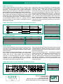
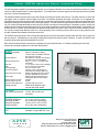
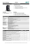
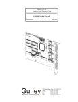
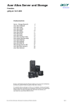
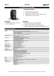
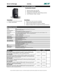
Gurley Model A25S Absolute Encoder Motion Type: Rotary Usage Grade: Industrial Output: Absolute Max Resolution: 17 2 (131,072 words) Compact, Fast & Accurate ingenuity@work Ò Gurley Precision Instruments' Model A25S absolute optical encoder is unique with its advanced design featuring new encoder technology. The following features make it far more capable than competitive products: ! Faster and more accurate than either a resolver-based system, or any competitive optical encoder. ! Up to 17-bit resolution, the highest available in an encoder designed and priced for industrial applications. ! A rugged, compact transducer (2.5" dia x 1.25" long) makes the encoder easier to design into tight spaces. ! Fully accurate data at 600 rpm permits use at higher shaft speeds. ! Very high data update rate (1 MHz parallel, 100 kHz serial) allows the encoder to be used whenever "real time" data is needed, such as velocity feedback applications or wide-bandwidth positioning servos. ! Unique circuitry eliminates hysteresis deadband, so there's no error due to bi-directional operation. ! Natural binary bus-compatible output permits straightforward hardware and software interfacing. ! Optional interface card simplifies communication between the encoder and a computer. ISO 9001 Certified Gurley Precision Instruments 514 Fulton Street Troy, NY 12180 U.S.A. (800) 759-1844, (518) 272-6300, fax (518) 274-0336, Online at www.gurley.com, e-mail: [email protected] GPI IIIIIIIIIIIIII SPECIFICATIONS MECHANICAL Maximum weights Steel transducer, 48” cable* Aluminum Transducer, 48” cable** External electronics Jacketed cable Moment of inertia Starting torque Running torque Max. recommended shaft load Axial Radial Bearings Code disc Max. operating speed Max. slew speed * TEMP = A or T ** TEMP = C 19 oz (540 g) 13 oz (370 g) 5 oz (140 g) 0.118 oz/in (132 g/m) 9.0 x 10⁻⁴ in-oz-s2 (63.2 g-cm2) 2.0 in-oz (14.0 x 10⁻³ N-m) 1.0 in-oz (7.0 x 10⁻³ N-m) 13 lb (58 N) 10 lb (45 N) Sealed ABEC 7 chrome on glass 600 rpm 10,000 rpm ENVIRONMENTAL Operating temperature Commercial Automotive Storage temperature Humidity Altitude Shock Vibration Transducer Electronics 32oF to +158oF (0oC to +70oC) -40oF to +185oF (-40oC to +85oC) -40oF to +194oF (-40oC to +90oC) 98% rh, non-condensing 0-50,000 ft, (0 - 15.24 km) 50 g, 11ms 15 g, 0-2000 Hz IP40 Ip60 ELECTRICAL Input power +5 Vdc ±0.25 Vdc, 300 mA max (excluding output buffer requirements) Illumination Light-emitting diodes, screened and rated for 100,00-hr life Max resolution 217 (131,072) unique words per shaft revolution (other resolutions available; see Ordering Info.) Accuracy Each data transition is within ±15 arcsec of its true position, regardless of resolution. The error distribution is such that each output code state is always present and in the correct order. Output code Natural binary (consult factory for other codes) Output format Parallel or serial Direction of increasing count User selectable (factory default = cw) Parity User selectable (factory default = odd) Parallel Output TTL-compatible tri-state buffered registers. Byte-wide or word-wide (user selectable) format. Input device Schmitt trigger input for interrogate pulse. TTL compatible output enable line(s). Max data update rate 1 MHz Serial output Synchronous output with EIA/RS-422 differential line drivers. MSB first; parity last Input device EIA/RS-422 differential line receivers for interrogate pulse and clock input. Max data update rate 100 [email protected] Mbaud NOTE: These specifications are applicable under all variations of recommended supply voltage, speed, temperature and direction of travel. Improved performance is available under special conditions; please consult factory. A25S Page 2 of 8 V3.1 ACHIEVING ACCURACY These design features assure the high accuracy and long-term stability of the Model A25S: ! Multiple reading heads are used in the transducer to eliminate errors caused by disc eccentricity, pattern irregularities and non-uniform bearing rotation. ! Back-to-back photodiodes "read" the interpolated track in pushpull configuration to eliminate errors caused by LED aging, temperature changes, supply voltage variations and other common-mode effects. ! Interpolation is accomplished with proprietary high-speed phase-angle conversion circuitry, which produces true position data very quickly and very accurately. The circuitry has been designed for reliable and predictable performance over the rated temperature environment. ! Because output data is made available only when the user provides an interrogate pulse, there is no possibility of "chatter" in the vicinity of a data transition, and hence no need for hysteresis in the circuitry. This unique zero-hysteresis feature assures error-free operation in bi-directional applications. ABSOLUTE POSITION ENCODING The Model A25S is a high performance absolute optical encoder designed for resolution in the 214-217 range. Its position information is stored in a non-volatile fashion in the multi-track absolute code pattern on the disc. If power is lost and re-applied, absolute position data is immediately available without "homing" the encoder or counting pulses, as is typically required with an incremental device. It is especially well-suited for applications requiring the highest possible data integrity where electrical noise, safety or high performance are important system considerations. ROBUST MECHANICAL DESIGN The A25S consists of a low-profile transducer module and separate electronics package - a configuration that allows it to be used where conventional designs will not fit. The rugged 3/8" dia shaft/bearing assembly assures long life in a variety of industrial applications. A proprietary electronic circuit permits the use of a lower resolution code disc; this minimizes sensitivity to optomechanical adjustments and thus maximizes long-term mechanical stability. REMOTE ELECTRONICS The separate electronics is housed in a compact 4.2" x 2.8" x 0.9" enclosure that can be located up to 25 ft from the transducer (standard cable length is 4 ft). APPLICATIONS The encoder is designed so that it may be connected directly to the data bus of a microprocessor or microcomputer. It offers the advantages of high accuracy, simplified hardware and software interfacing, robust opto-mechanical design, wide operating temperature range and very fast response time. The Model A25S is ideal for any motion control application requiring an absolute encoder with high resolution, accuracy and reliability in a compact configuration. Typical applications include robotics, precision servo controls, radar pedestals and similar AZEL mounts, rotary tables and machine tools. Gurley Precision Instruments 514 Fulton Street Troy, NY 12180 U.S.A. (800) 759-1844, (518) 272-6300, fax (518) 274-0336, Online at www.gurley.com, e-mail: [email protected] GPI IIIIIIIIIIIIII SPECIFICATIONS PARALLEL OUTPUT Position data is obtained from the encoder by issuing an active low interrogate pulse, which initiates a rotary-to-digital (R/D) conversion. The interrogate pin is a negative-edge-sensitive Schmitt trigger input and may be activated by any digital or analog signal that meets the stated input voltage requirements. R/D conversion proceeds independently of any other signal edge or state, and valid data is available at the output parallel register after 750 ns. Data remains valid until power is removed, or a new interrogate pulse is issued. A valid R/D conversion is not automatically initiated on power-up. Typically, 30-50 ms should be allowed on power-up before interrogation to permit power supplies to settle. Each parallel output line is buffered by a tri-state high speed CMOS bus driver compatible with virtually all TTL and CMOS 5-volt logic inputs. Two active-low output enables (chip selects) may be used to read high and low bytes separately, or they may be tied together for whole-word reads. (With 17-bit resolution, data is available as whole-word only). The parity bit is also tri-state, and is enabled in conjunction with the high byte. The user can select whether parity is odd or even with a jumper in the electronics package. Two or more encoders may share a byte-wide or word-wide output cable, provided conventional tri-state multiplexing restrictions are observed to avoid bus contention. TIMING AND SIGNAL CHARACTERISTICS FOR PARALLEL OUTPUT T0 T1 T2 T3 TIME T1 - T0 T2 - T0 T3 - T0 T4 - T0 T3 - T2 T4 - T3 T4 INT REG CONVERSION IN PROCESS NEW READING OE HIGH-IMPEDANCE DATA DC CHARACTERISTICS OEL, OEH VIH VIL TR TF CIN MIN 2.0 V -0.3 V MAX VCC + 0.3 V 0.8 V 500 ns 500 ns 20 pF INT VIH VIL TR TF CIN MIN 3.5 V -0.3 V DATA IOUT COUT MAX VCC + 0.3 V 1V MIN 100 ns 500 ns 750 ns 1 æs 100 ns 250 ns MIN -25 mA MAX ¥ ¥ ¥ ¥ ¥ ¥ MAX +25mA 20pF ¥ ¥ 15 pF SERIAL OUTPUT Position data is obtained from the encoder by issuing an active low pulse to the negative-edge-sensitive interrogate input while the clock input is held high; this initiates a rotary-to-digital (R/D) conversion. R/D conversion proceeds independently of any other signal edge or state, and valid data is available at the output serial register after 900 ns. Data remains valid until power is removed, or a new interrogate pulse is issued. A valid R/ D conversion is not automatically initiated on power-up. Typically, 30-50 ms should be allowed on power-up before interrogation to permit power supplies to settle. Serial output is buffered by RS422 differential line drivers, and is formatted MSB first, LSB last, followed by a parity bit. The user can select whether parity is odd or even by means of a jumper in the electronics package. Clock line must be held high until T2. Interrogation is triggered by falling edge of INT. New data bits become valid about 75 ns after rising clock edge. READ wave form is shown for reference. RS422 receivers and drivers are Fairchild mA9637A and mA9638, respectively. Receivers are terminated by a series RC network (220 W and 0.01 mF) spanning the true and complement Inputs. TIMING AND SIGNAL CHARACTERISTICS FOR SERIAL OUTPUT T0 T1 T2 T3 T4 T5 T6 INT 1 CLK DATA READ D16 2 D15 1 3 D14 2 4 D13 3 14 13 D12 4 D3 5 15 D2 16 D1 15 17 D0 16 PARITY 17 TIME T1- T 0 T2- T 0 T4- T 3 T6- T 5 MIN 00 ns 900 ns 100 ns 100 ns MAX ¥ ¥ ¥ ¥ 18 Complementary signals omitted for clarity A25S Page 3 of 8 V3.1 Gurley Precision Instruments 514 Fulton Street Troy, NY 12180 U.S.A. (800) 759-1844, (518) 272-6300, fax (518) 274-0336, Online at www.gurley.com, e-mail: [email protected] GPI IIIIIIIIIIIIII External Electronics Assembly ELECTRICAL INSTALLATION We recommend that the +5V supply (300 mA max, excluding atypical data bus termination requirements) for the encoder be provided from a linear regulated power supply located within 20 feet of the installation. Dual supply and return pins are provided to facilitate remote sensing, an option provided on most commercially available linear supplies. A cleanly regulated switch-mode power supply may be adequate in some cases. If the encoder is operated from the same supply as the customer's digital interfacing logic, an LC filter to suppress RFI on the instrument branch of the supply may be desirable. Where possible, terminate the instrument shield (Pin 13 and the D-Sub connector shell) at circuit ground potential as close as possible to the ground terminal of the power supply. The cover is effective primarily against electric field interference. In cases where intense magnetic field disturbances are expected, attention to cable routing and additional magnetic shielding may be wise precautions. These recommendations should be sufficient to assure reliable operation. However, optical encoder installations are known for their mechanical and electrical variety. Gurley will gladly render applications assistance for difficult installations. OUTPUT PINOUTS SHIELDED MALE 25-PIN D SUBMINIATURE CONNECTOR PIN 1 2 3 4 5 6 7 8 9 10 11 12 13 14 15 16 17 18 19 20 21 22 23 24 25 14-BIT D5 D4 D3 D2 D1 D0 NC NC OEL INT +5V +5V CASE D13 D12 D11 D10 D9 D8 D7 D6 OEH PAR GND GND 15-BIT D6 D5 D4 D3 D2 D1 D0 NC OEL INT +5V +5V CASE D14 D13 D12 D11 D10 D9 D8 D7 OEH PAR GND GND 16-BIT D7 D6 D5 D4 D3 D2 D1 D0 OEL INT +5V +5V CASE D15 D14 D13 D12 D11 D10 D9 D8 OEH PAR GND GND A25S Page 4 of 8 V3.1 17-BIT D8 D7 D6 D5 D4 D3 D2 D1 D0 INT +5V +5V CASE D16 D15 D14 D13 D12 D11 D10 D9 OE PAR GND GND SERIAL NC NC NC NC NC NC NC NC INT INT +5V +5V CASE NC NC NC NC NC NC DATA DATA CLK CLK GND GND SETTING THE DIP SWITCHES Open the electronics assembly by removing the 4 Philips-head screws and lifting off the top cover (the one with the label). The dip switches can be set as follows (this information is also printed on the pc board): Position 1 Position 2 ON OFF Count increases with CCW shaft rotation Parity is even Count increases with cw shaft Parity is odd SETTING THE DIP SWITCHES It may be desirable to unplug the electronics to snake the cable through a tight spot. First, open the electronics assembly by removing the 4 Philips-head screws and lifting off the top cover (the one with the label). Carefully unplug the ribbon cable and the separate shield connector from the electronics board. When re-mating the transducer to the electronics, make sure that they have the same serial number. A mismatch of these components will result in gross position errors and void the warranty. MOUNTING THE ELECTRONICS The simplest way to mount the electronics is with bracket AX06626 for a single box, or bracket AX06627 to mount a pair of boxes, as in an azimuth/elevation or other two-axis systems. Another choice is to bolt the box directly to a mounting surface: First, open the electronics assembly by removing the 4 Philips-head screws and lifting off the top cover (the one with the label). Unscrew 4 hex stand-offs, and lift out the electronics board and the cable; you don't have to unplug the cable from the pc board. Drill two clearance holes in diagonally opposite corners of the bottom of the lower cover. There's plenty of room under the pc board for screw heads. After the lower cover is bolted in place, carefully reassemble the package by reversing the previous three steps. Or, if your enclosure provides adequate mechanical and EMI protection, you can use the board without the box (order PKG code 0). You can mount the board on stand-offs, but be sure to provide adequate strain relief for the ribbon cable from the transducer. PERFORMANCE CERTIFICATION Before shipment, Gurley tests all absolute encoders for monotonicity, which guarantees that all output code states are present and in the correct order, and for accuracy, which verifies that the digital output matches the shaft angle input within the stated tolerance. These tests are performed on our exclusive METRA test system (Master Encoder for Testing Rotary Accuracy), and a printed accuracy plot accompanies each encoder. The heart of METRA is an exclusive Gurley-designed optical encoder with a resolution of 221 measuring steps/rev, and NIST-traceable absolute accuracy of ±1/3 arcsec. (The certified accuracy is limited by available angle standards, not by METRA itself.) When testing for accuracy, the encoder under test (EUT) is coupled to METRA with precision fixturing. As the two encoders are rotated together, the position information from METRA is used to interrogate the EUT at 2,097,152 positions around a revolution. Thus, this test verifies the location of every single output state of the EUT. This method reveals all encoder errors and does not depend on statistical assumptions based on an incomplete data set. Gurley Precision Instruments 514 Fulton Street Troy, NY 12180 U.S.A. (800) 759-1844, (518) 272-6300, fax (518) 274-0336, Online at www.gurley.com, e-mail: [email protected] GPI IIIIIIIIIIIIII Dimensions .10 [2.5] .093 [2.36] Gurley Precision Instruments 2.52 [64.0] MAX DIA Troy, NY 518-272-6300 MADE IN U.S.A. MODEL SER CUST 1.2500/1.2495 [31.750/31.737] PILOT DIA .3747/.3745 [9.517/9.512] SHAFT DIA .30 [7.6] 2.370 [60.20] DIA 1.23 [31.2] DIA 2.500 [63.50] DIA BASE CODE A .10 [2.5] PILOT 1.25 [31.8] 20 CONDUCTOR SHIELDED RIBBON CABLE 48" [1.2m] LONG (STANDARD) 300" [7.6m] MAX #6-32 X .20 [5.1] MIN THD DEPTH 3 HOLES EQUALLY SPACED ON A 2.160 [54.86] DIA B.C. 1.00 [25.4] .25 [6.4] 1.2500/1.2495 [31.750/31.737] PILOT DIA .10 [2.5] PILOT ELECTRONICS ASSEMBLY OPEN THIS SIDE ONLY CUST BASE CODE C 2.064 [52.43] TYP 2.55 [64.8] SQUARE .093 [2.36] SER Gurley Precision Instruments MODEL 4.21 [106.9] MAX Troy, NY 518-272-6300 MADE IN U.S.A. .221 [5.61] DIA THRU 4 HOLES .30 [7.6] 1.23 [31.2] DIA DB-25P .890 [22.61] MAX 2.83 [71.9] MAX 2.4995 [ 63.487 PILOT DIA +.0000 -.0005 +.000 -.013 ] BASE CODE E 2.625 [66.68] DIA .10 [2.5] PILOT ø.170 [4.32] THRU 2 PLCS .97 [24.6] MAX 1.85 [47.0] MAX .050 [1.27] 3.500 [88.90] .75 [19.1] AX06626 SINGLE BRACKET 3.84 [97.5] AX06627 DOUBLE BRACKET ALL DIMENSIONS ARE IN INCHES [MM] A25S Page 5 of 8 V3.1 Gurley Precision Instruments 514 Fulton Street Troy, NY 12180 U.S.A. (800) 759-1844, (518) 272-6300, fax (518) 274-0336, Online at www.gurley.com, e-mail: [email protected] GPI IIIIIIIIIIIIII MODEL ASC3N ABSOLUTE SERIAL INTERFACE CARD The ASC3N greatly simplifies communications between your computer and A25S, so you can use an absolute encoder for a wide variety of motion measurement or control applications. It provides all the necessary signals to interrogate and read in the data from up to 3 encoders simultaneously. The ASC3N and A25S transmit and receive data serially by RS-422 line drivers and receivers. The A25S requires an active low interrogate pulse to initiate a rotary-to-digital conversion. The ASC3N generates this signal, and sends it on a separate line simultaneously to each of the three encoders. When each encoder has converted rotary position into digital data, the ASC3N starts reading and shifting the serial data into its on-board shift registers. The shift/read clock is generated for all three channels in unison. You can control the data transmission rate to the ASC3N with convenient on-board jumpers. Parameters such the quality and length of the transmission line and application timing requirements will affect the maximum baud rate allowable. The baud rate can be from 28 kHz to 3.6 MHz, which correspond to maximum data update rates from 1,000 to 100,000 encoder reads per second. You can also configure the data size (from 14 to 17 bits) and parity (even or odd) by jumpers. When you are using more than one encoder, the data size and parity must be the same for all. The ASC3N checks the parity of the incoming data and reports any errors to the status register, which also has a “busy signal” bit that you can poll. Alternatively, you can assign an IRQ line and ignore the status register, if desired. A simple I/O read from the computer will input the data from the ASC3N to your CPU. Each ASC3N interface board comes with a comprehensive User's Manual and a 3.5" diskette containing test and utility software and example programs for both DOS and Windowsâ. GENERAL Hardware compatibility I/O base address Interrupt request level Data size Parity Axes Supported Connector Interface Serial input from encoder Serial output Maximum data clock rate Minimum data clock rate Maximum data update rate Mating encoder IBM® AT-compatible (or higher) computer with an available 16-bit ISA bus expansion card slot. 200-3F0 (hex); occupies 16 contiguous hex addresses (user selectable). IRQ 5, 7, 9, 10, 11, 15, NONE (user selectable). 14, 15, 16 and 17 bits (user selectable). Even or odd (user selectable). One, two or three axes. 3 female, 15-pin, high density Dsubminiature connectors (DE-15S). EIA/RS-422 differential line receivers. Encoder data MSB first, parity last. EIA/RS-422 differential line drivers, interrogate pulse and clock signal. 3.6 Mhz. 28 kHz. 100,000 reads per second. Model A25S absolute rotary encoder with serial output. ELECTRICAL Typ. Power requirements +5 Vdc, 500 mA max (w/o encoders). ENVIRONMENTAL Operating temperature Operating humidity Storage temperature Storage humidity 0°C to 70°C (32°F to 158°F). 0% to 90% (non-condensing). -20°C to 70°C (-4°F to 158°F). 0% to 95% (non-condensing). PHYSICAL Standard ¾ length IBM® PC Card. Size A25S Page 6 of 8 V3.1 Gurley Precision Instruments 514 Fulton Street Troy, NY 12180 U.S.A. (800) 759-1844, (518) 272-6300, fax (518) 274-0336, Online at www.gurley.com, e-mail: [email protected] GPI IIIIIIIIIIIIII MODEL SCA SHAFT COUPLING (OPTIONAL) ORDERING INFORMATION SCA 063 USER END fB USER END fB 04E 05E 06E 06M 08M 10M 1/4” shaft 5/16” shaft 3/8” shaft 6 mm shaft 8 mm shaft 10 mm shaft SPECIFICATIONS Kinematic accuracy with parallel offset = 0.1 mm [0.004 in] and angular misalignment = 0.09° Torsional rigidity ±10 arcsec 150 Nm/rad [0.1inoz/arcs] Maximum parallel offset 0.5 mm [0.020 in] Maximum axial extension or com pression 0.5 mm [0.020 in] Maximum angular misalignm ent 1° 22 [.87] ø9.53 [.375] 10 [.39] 10 [.39] 30 [1.18] DIA SOCKET HEAD CAP SCREWS (SEE NOTE 2) øB (SEE NOTE 3) NOTES: 1. DIMENSIONS ARE IN MM [IN]. 2. IF øB IS IN INCHES, SCREWS ARE 4-40 X 5/16. IF øB IS IN MM, SCREWS ARE M3 X 8. 3. TOLERANCE ON USER'S SHAFT IS ±.012 [±.0005]. A25S Page 7 of 8 V3.1 Gurley Precision Instruments 514 Fulton Street Troy, NY 12180 U.S.A. (800) 759-1844, (518) 272-6300, fax (518) 274-0336, Online at www.gurley.com, e-mail: [email protected] GPI IIIIIIIIIIIIII ORDERING INFORMATION - - A25S CODE RES FORMAT CODE B CABLE BASE SHAFT PKG TEMP SF PKG - Electronics package 0 PC board assembly only 1 With enclosure Natural Binary RES - Resolution, words/rev 17 217 (131,072) 16 216 (65,536) 15 215 (32,768) 14 214 (16,384) TEMP - Operating temperature range C Commercial (0 to +70°C) A Automotive (-40 to +85°C) T Transducer only (-40 to +85°C) FORMAT - Data transmission S Serial, RS-422 diff. line driver P Parallel, tri-state TTL SF - Special feature # Issued at time of order to cover special customer requirements N No special features CABLE - Cable length in inches 048 Standard 006 Minimum 300 Maximum BASE A C E Combination Synchro/face mount 1.25” pilot dia Square-flange mount Synchro mount, 2.5” pilot dia ACCESSORIES (order separately) M04 ASC3N CAMxxx SCA06Exxx AX06399 AX06626 AX06627 Mating connector for DB-25P IBMâ PC serial interface card (see page 6) Cable, A25S elect to ASC3N, xxx = length, inches (Max. Length = 600) Shaft coupling (see page 7) Synchro cleat kit to mount transducer Bracket for one electronics box Bracket for two electronics boxes SHAFT 06E 3/8” dia. SPECIAL CAPABILITIES For special situations, we can optimize catalog encoders to provide higher frequency response, greater accuracy, wider temperature range, reduced torque, non-standard line counts, or other modified parameters. In addition, we regularly design and manufacture custom encoders for user-specific requirements. These range from high-volume, low-cost, limited-performance commercial applications to encoders for military, aerospace and similar high-performance, highreliability conditions. We would welcome the opportunity to help you with your encoder needs. WARRANTY Gurley Precision Instruments offers a limited warranty against defects in material and workmanship for a period of one year from the date of shipment. A25S Page 8 of 8 V3.1 Gurley Precision Instruments 514 Fulton Street Troy, NY 12180 U.S.A. (800) 759-1844, (518) 272-6300, fax (518) 274-0336, Online at www.gurley.com, e-mail: [email protected] GPI IIIIIIIIIIIIII