1
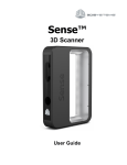
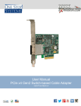
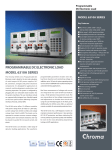
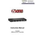
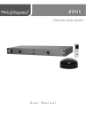
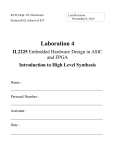
HPLS36ADxx/DDxx/APxx/A The DRAGON series High Power LED Light Sources Features Description • Plugandplay frame for LEDs • Interchangeable LED heads • Interchangeable LED heads provided • 455nm, 475nm, 505nm, 530nm, 590nm, 617nm, 630nm, white 5500 K, white 3300 K • Selection of collimating optics/ attachments • Selection of base units • Fast analog control • Fast analog control (some models) • Lownoise CW control • Lownoise CW control (some models) • Fast pulsed (digital) control • Fast pulsed (digital) control (some models) • Narrow bandwidth or broadband • Wide field or focused output • Continuous, waveforms, or pulses to <150ns • Up to 400mW CW, x5 intensity short pulse • Accepts LEDs with 0.2”, 0.4”, 0.6”, 0.8”, 1”, 1.2” pin spacing • Mounting to standard and metric posts (832 and M4x0.75 threads in base unit) • Base unit diameter 1.450” (36.8mm) The HPLS36 series of high power LED light sources are designed as flexible system of interchangeable components for applications where it is hard to standardize the requirements for massproduction. Building a system comes down to (1) selection of appropriate base with specific functionality and type of control; (2) selection of LED head[s] and (3) focusing optics specific for the application. Functionality of base units include fast analog control (to generate any optical function, sine, saw, square, CW…); lownoise CW control (for applications where ATClike or PWM algorithms may cause problem); and fast pulsed (digital) control (faster and more powerful then analog). Selection of the way the optical power is set include external digital/analog signal supplied thru connector (BNC/Twin BNC), or, for CW application, BuiltIn Potentiometer/ Remote Potentiometer/ 2level Switch). LED heads are currently available in two formfactors: LEDHRxxx series, precollimated with buildin reflector and 1.2” pin spacing for closerange illumination, and LEDHxxx series with 0.8” pin spacing for higher performance and wider selection of focusing optics. Many other models of LEDs can be adapted. The function of focusing optics is to direct the light to the certain spot size on certain distance as required and often custom designed for specific application. Most of new optics is backwardcompatible (fits the units previously shipped) Applications • Fluorescence excitation • Highspeed imaging • Synchronous detection • Machine vision • Biomedical optics Typical system configuration Base unit with specific functionality LED Heads Optics 1 Lightspeed Technologies Service and Solutions at the speed of light P.O. Box 110161 Campbell, CA 95011 (408)7610062 (408)3783629 fax www.lightspeedtech.com sales@lightspeedtech.com Base Units Ordering information Model Brief description Functionality and controls Detailed description HPLS36 DD500 500mA digital driver Base unit with builtin 500mA "digital" (triggered) driver for PWM/triggering, any duty cycle up to CW. Accepts LED heads with 0.21.2 inch pin spacing. (LEDH, LEDHR) Driver: buildin, light is triggered by external signal, TTL/CMOS input 3V5V, BNC connector. 150 ns rise time, 200ns fall time. From 300ns pulses to CW, any repetition rate. Power requirements: 12V, 0.5A. HPLS36 AD500 500mA analog/digital driver HPLS36 AD3500 500mA analog 3500mA digital driver Power connector: 12V500mA Signal connector: Digital input Switch: Aim 1OFFON Power connector: 12V/0.5A Signal connector: A/D input Switch: mode DOFFA Power connector: 12V/1.0A Signal connector: A/D input Switch: mode DOFFA HPLS36 AD3500DI dual input variant HPLS36 DD7500 HPLS36 AP(750, 1000) HPLS36 AR(750, 1000) HPLS36 AT(750, 1000) Power connector: 12V/1.0A Signal connector: A&D input Switch: Aim 0OFF1 faster rise time, Power connector: higher intensity 24V/0.5A Signal connector: Digital input Switch: Aim 0OFF1 CW, with buildin Power connector: potentiometer 4.55V/1A Potentiometer: current adjust Switch: power AdjOFFMax CW, with remote Power connector: potentiometer 4.55V/1A Signal Connector: ext pot/signal Switch: power AdjOFFMax CW, twolevel Power connector: control 4.55V/1A Blank plug Switch: power 1OFF2 Base unit builtin 500mA driver. Analog or digital mode, selectable by switch on control panel. Accepts LED heads with 0.21.2 inch pin spacing. (LEDH, LEDHR) Digital mode: light is triggered by external signal, TTL/CMOS input 3V5V, BNC connector; 150 ns rise time, 200ns fall time; from 300ns pulses to CW, any repetition rate. Analog mode: optical output is proportional to the analog signal applied, <2us stab time, selectable format 05V, 010V, 420mA, 020mA. Power requirements: 12V, 0.5A. Base unit with builtin driver, for high current at low duty cycle/ pulse busts app. Analog mode (500mA) or digital mode (3.5A), selectable by switch on control panel. Accepts LED heads with 0.2 1.2 inch pin spacing. (LEDH, LEDHR) Digital mode: light is triggered by external signal, TTL/CMOS input 3V5V, BNC connector; 150 ns rise time, 200ns fall time; Smart Time Limiting circuitry limits cumulative energy delivered to LED for protection. Single pulse length range: 0.5us 1 ms, maximum duty cycle of pulse train is 10%, average active time/relaxation time ratio is 1:10. Any repetition rate. Analog mode: optical output is proportional to the analog signal applied, <2us stab time, selectable format 05V, 010V, 420mA, 0 20mA. Power requirements: 12V, 0.5A (included) Same as HPLS36AD3500 but Dual Inputs for simultaneous Analog and Digital Control. Twin BNC connector. Test mode for aiming. Twin BNC cable, power supply included Base unit with builtin 7.5A driver for applications where faster fall/rise time, short pulses at low duty cycle are required. Light is triggered by external signal, TTL/CMOS 35V, BNC connector, 117ns rise time, 45ns fall time. Optical pulse halfwidth matching the halfwidth of starting pulse. Smart Time Limiting circuitry limits cumulative energy delivered to LED. Single pulse length range 50ns 40us, maximum duty cycle of pulse train 3.3%, average active/relaxation time ratio is 50:1. Any repetition rate. Base unit with builtin lownoise linear driver and manual analog control. Current 0750mA/01A specify. Two operating modes, selectable by the switch on control panel: fixed maximum power or adjustable by potentiometer knob. Switch momentarily between 2 levels. Easy to change LED heads, 7 different colors and 2 shades of white. Accepts LED heads with 0.21.2 inch pin spacing. (LEDH, LEDHR). Power requirements: 4.55V, 1A (included) Base unit with builtin lownoise linear driver and manual analog control. Current 0750mA/01A specify. Two operating modes, selectable by the switch on control panel: fixed maximum power or adjustable by potentiometer knob. Switch momentarily between 2 levels. Easy to change LED heads, 7 different colors and 2 shades of white. Accepts LED heads with 0.21.2 inch pin spacing. (LEDH, LEDHR). Power requirements: 4.55V, 1A. Base unit with builtin lownoise linear driver and 2level power control by the ONOFFON switch on the control panel. Suffix 750/1000 specify. Current levels: 500, 750 mA for model with suffix "750". Currents of 500mA, 1000mA for model with suffix "1000". Switch momentarily between 2 levels. Easy to change LED heads, 7 different colors and 2 shades of white. Accepts LED heads with 0.2 1.2 inch pin spacing. (LEDH, LEDHR). Power requirements: 4.55V, 1A (included) 2 Lightspeed Technologies Service and Solutions at the speed of light P.O. Box 110161 Campbell, CA 95011 (408)7610062 (408)3783629 fax www.lightspeedtech.com sales@lightspeedtech.com Base Unit HPLS36AD3500 Description HPLS Base Unit with builtin 2channel driver. Analog channel has linear control and continuously variable output, with 1% input offset to ensure shutdown when signal is not applied. Digital channel has 2level ONOFF control (active HI). Output current in the sum of outputs of both channels. Switch on the control panel selects which channel is addressed by input BNC connector, thus selecting Digital or Analog mode. There is an important difference between the output stages of Analog and Digital channels. Analog channel operates in current regulation mode using a feedback from the current sensor in the output stage. Digital channel, on the other hand, provides fast switching while the current is limited by the resistor (without active feedback). This is because the channels are optimized for different purposes: Analog channel is designed to convert the input voltage into output current as precisely as possible and as fast as reasonable but not to hurt the precision; while Digital is optimized for switching the current to MAX level and back to 0 as fast as possible. As a side effect, the current in Digital mode varies slightly for different LED head; while the Analog channel current is regulated to be the same. Base unit accepts LED heads with 0.21.2 inch pin spacing. (LEDH, LEDHR). Accepts focusing optics and attachments mounted on LED head directly and models that have index “36” in a part number. Common Specifications HPLS36AD3500 block diagram • Two operating modes: Analog/Digital • Dimensions: Ø1.45x4.5” (36.8x115mm) • Weight: 0.66 lb (0.3 kg) • Power Requirement: 12V, 0.5A • Power Connector: 5.5/2.1 mm Power Jack, center positive, barrel common ground • Control Signal Connector: BNC • Thermal resistance, convection: 5 C/Watt Absolute Maximum Ratings • Power Input: 1 to 14V; 2A to 2A; fuse protected (2A) • Signal Input, Digital Mode: 2.5V to 7V; 50mA max, 50 Ohm input impedance • Input, Analog Mode: 10V to 20V Power Indicator LED Linear regulators Input switch Output Digital channel Current sensor Analog channel HPLS36AD3500 control panel: Switch function: mode selection • Left: Digital mode • Center: OFF • Right: Analog mode BNC connector: • Central pin: input signal • Barrel: common ground LED: input power indicator 1 13 LED head connector: • 13 pins x 0.1” pitch • Pins 16, marked red or yellow: positive • Pin 7: NC • Pins 813: negative • Accepts 0.025” (0.64m) square pins, 0.230” long HPLS36AD3500 exterior view, dimensions and mounting interface. 3 Lightspeed Technologies Service and Solutions at the speed of light P.O. Box 110161 Campbell, CA 95011 (408)7610062 (408)3783629 fax www.lightspeedtech.com sales@lightspeedtech.com Base Unit HPLS36AD3500 Waveforms and specifications Digital mode specifications: • • • • • • • • • • • • • • • Output current: 3.5A +/ 0.3A (LED head dependent) Rise Time: 80ns (to 1/2 level); 200ns (to 90%) Rise front propagation delay: 100ns typ Fall Time: 140ns (to ½ level); 200ns (to 90%) Fall front propagation delay: 200ns Pulse front/fall jitter: < 10ns, <5ns typ Nominal Signal Level: 3.35V; TTL/CMOS Logical “0” (light OFF): <0.8V Logical “1” (light ON): >2.4V Smart Time Limiting Circuitry for LED Protection Limits the Cumulative Energy Delivered to LED Single Control Pulse length range: 50ns1ms Maximum Duty Cycle of Continuous Waveform: 10% Average Ratio, Active Time/Relaxation Time: 1:10 Any Repetition Rate Trimmer on the Board to Down Regulate the Pulsed Current and Optical Power Digital mode, Example 1: 1us control pulse (blue), optical pulse (red) Digital mode, protocol examples: • Example 1: 1us pulse permitted every 10us • Example 2: 1 ms max duration pulse every 10ms • Example 3: 50% duty cycle waveform 2ms total duration, permitted every 10ms • Example 4: 20% duty cycle waveform 5ms total duration, permitted every 10ms • Example 5: 200ns starting pulse: optical pulse has Gaussian profile, 420ns(1/2), peak is 100% of steady level • Example 6: 100ns starting pulse: optical pulse has Gaussian profile, 270ns(1/2), peak is 80% of steady level • Example 7: 50ns starting pulse: optical pulse has Gaussian profile, 200ns(1/2), peak is 60% of steady level Analog mode specifications: • • • • • • • • • • • Input/Output relationship: Linear, 1% offset Output current, continuously variable: 0500mA Output current drift: < 800ppm/hour Output current accuracy: +/3% of set value Output current RMS noise: <0.5% Input Signal Format: User Programmable (4Dip switch on the driver board) Input Signal Format (Default): 05V Input Signal Formats: 010V; 020mA, 420mA Rise Time/Delay for 0250mA transit: 400ns(50%), 1.2us(90%) / 1.8us Delay Fall Time/Delay for 2500mA transition: 750ns(50%), 500ns(90%)/ 20ns Delay Rise Time/Delay for 50300mA transition: 350ns(50%), 800ns(90%); 20ns Delay Digital mode, Example 1: 1us control pulse every 10us (blue), optical pulse (red) Digital mode, Example 2: 1ms control pulse every 12ms (blue), optical pulse (red) Analog mode, sawtooth pattern 8kHz. Control pulse (blue), optical pulse (red) 4 Lightspeed Technologies Service and Solutions at the speed of light P.O. Box 110161 Campbell, CA 95011 (408)7610062 (408)3783629 fax www.lightspeedtech.com sales@lightspeedtech.com Base Unit HPLS36AD3500DI Description HPLS Base Unit with builtin 2channel driver. HPLS36AD3500DI is Dual Input variant of HPLS36AD3500. Analog channel has linear control and continuously variable output, with 1% input offset to ensure shutdown when signal is not applied. Digital channel has 2level ONOFF control (active HI). Output current in the sum of outputs of both channels. Twin BNC connector on a control panel allows simultaneous access to both channels. Aiming mode for Analog channel (by the switch on control panel) provides easy aiming and testing. There is an important difference between the output stages of Analog and Digital channels. Analog channel operates in current regulation mode using a feedback from the current sensor in the output stage. Digital channel, on the other hand, provides fast switching while the current is limited by the resistor (without active feedback). This is because the channels are optimized for different purposes: Analog channel is designed to convert the input voltage into output current as precisely as possible and as fast as reasonable but not to hurt the precision; while Digital is optimized for switching the current to MAX level and back to 0 as fast as possible. As a side effect, the current in Digital mode varies slightly for different LED head; while the Analog channel current is regulated to be the same. Base unit accepts LED heads with 0.21.2 inch pin spacing. (LEDH, LEDHR). Accepts focusing optics and attachments mounted on LED head directly and models that have index “36” in a part number. Common Specifications HPLS36AD3500DI block diagram • Two channels: Analog and Digital • Dimensions: Ø1.45x4.5” (36.8x115mm) • Weight: 0.66 lb (0.3 kg) • Power Requirement: 12V, 0.5A • Power Connector: 5.5/2.1 mm Power Jack, center positive, barrel common ground • Control Signal Connector: Twin BNC • Thermal resistance, convection: 5 C/Wt Absolute Maximum Ratings • Power Input: 1 to 14V; 2A to 2A; fuse protected (2A) • Signal Input, Digital Mode: 2.5V to 7V; 50mA max, 50 Ohm input impedance • Input, Analog Mode: 10V to 20V Power Indicator LED Linear regulators Input switch Output Digital channel Current sensor Analog channel HPLS36AD3500DI control panel: Switch function: analog channel mode • Left: normal (external control) • Center: Analog OFF • Right: Aiming ON (500mA) Twin BNC connector: • Male pin: digital channel • Female pin: analog channel • Barrel: common ground LED: input power indicator 1 HPLS36AD3500[DI] exterior view, dimensions and mounting interface. HPLS36AD3500 shown. DI has different signal connector (twin BNC) and switch notations. 13 LED head connector: • 13 pins x 0.1” pitch • Pins 16, marked red or yellow: positive • Pin 7: NC • Pins 813: negative • Accepts 0.025” (0.64m) square pins, 0.230” long 5 Lightspeed Technologies Service and Solutions at the speed of light P.O. Box 110161 Campbell, CA 95011 (408)7610062 (408)3783629 fax www.lightspeedtech.com sales@lightspeedtech.com Base Unit HPLS36AD3500DI Waveforms and specifications Digital mode specifications: • • • • • • • • • • • • • • • Output current: 3.5A +/ 0.3A (LED head dependent) Rise Time: 80ns (to 1/2 level); 200ns (to 90%) Rise front propagation delay: 100ns typ Fall Time: 140ns (to ½ level); 200ns (to 90%) Fall front propagation delay: 200ns Pulse front/fall jitter: < 10ns, <5ns typ Nominal Signal Level: 3.35V; TTL/CMOS Logical “0” (light OFF): <0.8V Logical “1” (light ON): >2.4V Smart Time Limiting Circuitry for LED Protection Limits the Cumulative Energy Delivered to LED Single Control Pulse length range: 50ns1ms Maximum Duty Cycle of Continuous Waveform: 10% Average Ratio, Active Time/Relaxation Time: 1:10 Any Repetition Rate Trimmer on the Board to Down Regulate the Pulsed Current and Optical Power Digital mode, Example 1: 1us control pulse (blue), optical pulse (red) Digital mode, protocol examples: • Example 1: 1us pulse permitted every 10us • Example 2: 1 ms max duration pulse every 10ms • Example 3: 50% duty cycle waveform 2ms total duration, permitted every 10ms • Example 4: 20% duty cycle waveform 5ms total duration, permitted every 10ms • Example 5: 200ns starting pulse: optical pulse has Gaussian profile, 420ns(1/2), peak is 100% of steady level • Example 6: 100ns starting pulse: optical pulse has Gaussian profile, 270ns(1/2), peak is 80% of steady level • Example 7: 50ns starting pulse: optical pulse has Gaussian profile, 200ns(1/2), peak is 60% of steady level Analog mode specifications: • • • • • • • • • • • Input/Output relationship: Linear, 1% offset Output current, continuously variable: 0500mA Output current drift: < 800ppm/hour Output current accuracy: +/3% of set value Output current RMS noise: <0.5% Input Signal Format: User Programmable (4Dip switch on the driver board) Input Signal Format (Default): 05V Input Signal Formats: 010V; 020mA, 420mA Rise Time/Delay for 0250mA transit: 400ns(50%), 1.2us(90%) / 1.8us Delay Fall Time/Delay for 2500mA transition: 750ns(50%), 500ns(90%)/ 20ns Delay Rise Time/Delay for 50300mA transition: 350ns(50%), 800ns(90%); 20ns Delay Digital mode, Example 1: 1us control pulse every 10us (blue), optical pulse (red) Digital mode, Example 2: 1ms control pulse every 12ms (blue), optical pulse (red) Analog mode, sawtooth pattern 8kHz. Control pulse (blue), optical pulse (red) 6 Lightspeed Technologies Service and Solutions at the speed of light P.O. Box 110161 Campbell, CA 95011 (408)7610062 (408)3783629 fax www.lightspeedtech.com sales@lightspeedtech.com Base Unit HPLS36DD7500 Description HPLS Base Unit with builtin “digital” driver. Operating principles are similar to the Digital channel of HPLS 36AD3500, but further optimized for faster response and higher output current. Has 2level ONOFF control (active HI). Halfwidth of the optical pulse is optimized to match the halfwidth of starting pulse to +/15ns accuracy with wide range of pulse length changes. Aiming mode (by the switch on control panel) provides easy aiming and testing by running 150mA CW current thru LED. Digital driver of HPLS36DD7500 is optimized for switching the current to MAX level and back to 0 as fast as possible, without active feedback, thus providing ultimate highspeed LED light source. As a side effect, the current may vary slightly for different LED heads with different voltage requirements. Refer to the specifications for typical variations. Base unit accepts LED heads with 0.21.2 inch pin spacing. (LEDH, LEDHR). Accepts focusing optics and attachments mounted on LED head directly and models that have index “36” in a part number. Common Specifications HPLS36DD7500 block diagram: • Two modes: Digital / Aiming • Dimensions: Ø1.45x4.5” (36.8x115mm) • Weight: 0.66 lb (0.3 kg) • Power Requirement: 24V, 0.5A • Power Connector: 5.5/2.1 mm Power Jack, center positive, barrel common ground • Control Signal Connector: BNC • Thermal resistance, convection: 5 C/Wt • Cooling: convection Absolute Maximum Ratings • Power Input: 1 to 30V; 2A to 2A; fuse protected (2A) • Signal Input, Digital Mode: 2.5V to 7V; 50mA max, 50 Ohm input impedance Power Input switch Indicator LED Digital channel Output CW 150mA HPLS36DD7500 control panel: Switch function: Aim • Left: aim OFF • Center: aim OFF • Right: Aiming ON (150mA) BNC connector: • Center: TTL/CMOS input • Barrel: common ground LED: input power indicator 1 13 LED head connector: • 13 pins x 0.1” pitch • Pins 16, marked red or yellow: positive • Pin 7: NC • Pins 813: negative • Accepts 0.025” (0.64m) square pins, 0.230” long HPLS36DD7500 exterior view, dimensions and mounting interface. 7 Lightspeed Technologies Service and Solutions at the speed of light P.O. Box 110161 Campbell, CA 95011 (408)7610062 (408)3783629 fax www.lightspeedtech.com sales@lightspeedtech.com Base Unit HPLS36DD7500 Waveforms and specifications Digital mode specifications: • • • • • • • • • • • • • • • Output current: 7.5A +/ 1A (LED head dependent) Rise Time: 45ns (to 1/2 level); 117ns (to 90%) Rise front propagation delay: 100ns +/5 Fall Time: 30ns (to ½ level); 45ns (to 90%) Fall front propagation delay: 100ns +/5 Pulse front/fall jitter: 10ns MAX, <5ns typ Nominal Signal Level: 3.35V; TTL/CMOS Logical “0” (light OFF): <0.8V Logical “1” (light ON): >2.4V Smart Time Limiting Circuitry for LED Protection Limits the Cumulative Energy Delivered to LED Single Control Pulse length range: 50ns40us Matching optical pulse halfwidth (50ns40us) Maximum Duty Cycle of Continuous Waveform: 3.3% Average Ratio, Active Time/Relaxation Time: 1:50 Any Repetition Rate Example 1: 1.025us control pulse (blue), matching 1.017ns optical pulse (red) Digital mode, protocol examples: • Example 1: 1us pulse produces optical pulse with matching within +/15ns accuracy. 1 us pulse is permitted every 30us • Example 2: 100 ns starting pulse produces optical pulse with matching to +/15ns accuracy • Example 3: 10us starting pulse produces virtually “rectangular” optical pulse • Example 4: Too long starting pulse will be cut by Time Limiting Circuitry to 40 us. • Example 5: 100ns starting pulse will produce 100 ns optical pulse with peak which is 88% of steady level observed with 1us pulse. Further shortening the pulse will lower the peak more. Example 2: 100ns control pulse (blue); 108ns optical pulse (red) Example 3: 10 us control pulse (blue), optical pulse (red) Example 5: Illustration how the position of fall front of starting pulse (blue, violet) affects the shape of optical pulse (red, purple) Example 4: 80us starting pulse (blue) cut to 40us optical pulse (red) by Time Limiting Circuitry 8 Lightspeed Technologies Service and Solutions at the speed of light P.O. Box 110161 Campbell, CA 95011 (408)7610062 (408)3783629 fax www.lightspeedtech.com sales@lightspeedtech.com LED Heads LEDH, LEDHR series Specifications p.1 LEDH and LEDHR are userreplaceable, LEDbased light sources, attached to the HPLS36 series base units, which provide electrical connection to the driver, means of mechanical mounting and the heat dissipation from the LED. Available in two form factors – LEDHR, bigger, with buildin reflector to collimate the light emitted from the LED, and LEDH, smaller, higher performance, uncollimated light source. Reference to the table below for typical optical power achievable by 14 different models of LED heads when plugged into various HPLS36 models. For spectral information, form factors, and temperature coefficient of optical power, see the next page. Table 1. Optical power range of various models of LED heads vs. HPLS36 model, current, and duty cycle. (1) Note: Optical power for LEDHR is measured after reflector, using 2” (5cm) diameter optical power meter placed on optical axes 4” (10 cm) from the LED (2) Note: For LEDH, the optical power is total of the chip before any optics, and measured by 2” (5cm) diameter optical power meter placed on optical axes touching the LED lens. (3) Due to the nature of the semiconductor structures involved, important parameter of LEDs such as optical power, maximum current that LED can tolerate, spectrum and voltage drop, vary greatly for different batches and affect the performance of the HPLS36 series light sources. It is not uncommon that the power of LEDs from different batches differs 2 times and more. The information presented here should be used for reference only. Please ask if your application demands more stringent requirements. (4) Optical power is measured with LED head attached to the HPLS36 unit, at the room temperature 25C. (5) Optical power indicated is power range while ON, for Digital models, and maximum power for continuously variable models. Please note the 2channel models such as AD3500 and AD3500DI, presented in 2 columns, for digital and analog channels, respectively. (6) Duty cycle affects the performance of LEDs. Typically, for a given current, optical power is higher for lower duty cycle due to lower heating effect of the LED chip. For the pulsed units, exceeding duty cycles indicated for the given current can cause permanent damage to the LED. Some HPLS36 models have builtin protection against exceeding duty cycle, however, due to wide spread of duty cycle requirements and flexible nature of HPLS36 series, it is impossible to satisfy to all the requirements in one unit. 9 Lightspeed Technologies Service and Solutions at the speed of light P.O. Box 110161 Campbell, CA 95011 (408)7610062 (408)3783629 fax www.lightspeedtech.com sales@lightspeedtech.com LED Heads LEDH, LEDHR series Specifications p.2 Typical spectra, 455, 470, 505, 530, 595, 617, 630nm Optical power vs. temperature for 595, 617, 630nm LED heads Typical spectrum for warm white, 3500K LED Optical power vs. temperature for 455, 470, 505, 530, LED heads Typical spectrum for white 5500K LED Ordering information: LEDH[R] XXXX (color, temperature) – XXXX (performance model, for LEDH only) 455 (royal blue) omitted: 1.0x1.0 mm die, basic performance 470 (blue) 3: 1.0x1.0mm die, high brightness, high power 505 (cyan) 5: 3x3mm die, moderate brightness, high power 530 (green) K2: 1.0x1.0mm die, best brightness, best power 590 (amber) 617 (red orange) 630 (red) 3500 (warm white) 5500 (bright white) examples: LEDHR470: blue, 1.2” pitch, with reflector, basic performance LED head LEDH530: green, 0.8” pitch, basic performance LED head. LEDH455K2: royal blue, 0.8” pitch, best brightness/power LED head. LEDH exterior view 10 Lightspeed Technologies Service and Solutions at the speed of light P.O. Box 110161 Campbell, CA 95011 LEDHR exterior view (408)7610062 (408)3783629 fax www.lightspeedtech.com sales@lightspeedtech.com Collimators, 60mm diameter lens General description. Collimators OH3660x140210 (variable focal length) and OH3660x135 (fixed focal length) are designed as optical attachments for HPLS36 light sources. They represent illumination quality optics optimized for throughput efficiency rather then imaging therefore some aberrations in the LED chip image (such as lowintensity halo around main spot at some focusing settings) are inherent and therefore acceptable. Collimator OH3660x130200, with HPLS36 attached, shown as set to 150mm focal length OH3660x140210 specifications: • Effective focal length: 140210mm • Main lens diameter: 60mm • Clear optical aperture: 57mm F#: 2.453.68 • Light collection efficiency (geometrical factor): 4.82% min • • Overall efficiency (with reflection losses): 4.21.75% min Spot size, LEDH head (1.4x1.4mm emitter), at 84” (213cm) • • distance: adjustable, 23x23m – 15x15mm MIN • Operating range at f=140mm: 70cm (7x7mm spot) – infinity • Operating range at f=210mm: 55cm (4x4mm spot) infinity • • Weight, collimator only: 315g • • • • • • • OH3660x135 specifications: Effective focal length: 135mm Main lens diameter: 60mm Clear optical aperture: 57mm F#: 2.37 NA: 0.21 Light collection efficiency (geometrical factor): 4.4% min Overall efficiency (including reflection losses): 4.04.2% Spot size, LEDH head (1.4x1.4mm emitter), at 84” (213cm) distance: 22x22mm MIN Weight, collimator only: 350g Collimator OH3660x135, with HPLS36 attached, typical dimensions as set to image at infinity. 11 Lightspeed Technologies Service and Solutions at the speed of light P.O. Box 110161 Campbell, CA 95011 (408)7610062 (408)3783629 fax www.lightspeedtech.com sales@lightspeedtech.com Terms and Conditions Prices and Quotations All quotations are valid for 30 days unless stated otherwise. Published prices are subject to change without notice. Custom and specialty products are individually priced per requirements specified and subject to change if changes are made from original request. Purchase Orders and Payment Methods Orders are accepted by email, mail, and fax. Verbal orders are not advised but accepted on individual basis. Payments by Net 30 account upon approval of credit or by credit card. Late fee 2% per month invoiced if past due. International customers: 100% prepayment, credit card, or wire transfer Net 30 with approved credit. Delivery and shipping. Shipments are made domestically by USPS priority or FedEx prepaid and added to invoices unless shipping method and shipping account number provided with order. International shipments do not include importation or duty fees and international shipping charges are specified with product quotes. Safety warnings and operating conditions. Lightspeed Technologies is not liable for equipment damage or personal injury resulting from the use of these products. Do not look into the beam directly, or stare at the specular reflection from reflective surfaces such as mirrors. Do not operate unless LED head is secured by 2 screws. Do not disassemble drivers unless to access userlevel controls inside per user manual. Do not operate outdoors, in high humidity or condensing environment. HPLS series of light sources and drivers are designed for operation in indoor environment, noncondensing conditions, with ambient temperature from 4.5°C to 29.5°C (40°F to 85°F). Warranty Terms and Conditions Lightspeed Technology’s products, HPLS base units, drivers, optics, accessories (except LED heads) are warranted to be free from manufacturing defects in materials, parts and labor for a period of 1 year from the date of delivery to a customer, customer’s shipping department, and/or designated agent. Components that are subject for failure per conditions specific to customer’s testing environment, including but not limited to, incompatible line outlet voltage, outofthespecifications line outlet voltage, incompatible signal voltages and/or timing requirements; specifically including, but not limited to, LED heads, are warranted for a period of 90 days. Returns and cancellation conditions. No returns on special order items, or if a demo unit was requested, furnished and subsequently tested by a customer prior to placing an order. All products should be returned with original packaging material. All returns are subject to inspection and restocking fees upon arrival if without original packaging, damaged, or otherwise tampered with. Contact Lightspeed Technologies for a return materials authorization (RMA) number and shipping address if product is to be returned. No returns after 30 days from the day of product delivery to a customer, shipping department, or designated agent. Lightspeed Technologies will make the determination of cause of damage and if warranty replacement is applied. Lightspeed Technologies P.O. Box 110161 Campbell, CA 950110161 (408)7610062 sales@lightspeedtech.com 12 Lightspeed Technologies Service and Solutions at the speed of light P.O. Box 110161 Campbell, CA 95011 (408)7610062 (408)3783629 fax www.lightspeedtech.com sales@lightspeedtech.com