1
Creating Application Software
6.13.1
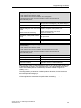
Configuration of a UPS
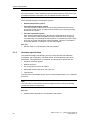
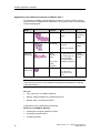
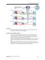
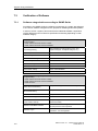
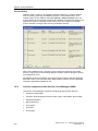
The following table contains an example of the configuration of an uninterruptible
power supply for an operator station in a process control system. The same basic
procedure can be used with automation stations.
Scenario
6.13.2
Action
Reaction
1
Power failure
< 10 seconds
The process control system computers are buffered by
the UPS. An alarm using a digital input in the process
control system documents the power failure.
2
Power failure
>20 minutes.
Power returns
after 25
minutes
The process control system computers are buffered by
the UPS, e.g., for 20 minutes. An alarm in the process
control system documents the power failure and the
shutdown of the process control system after 20
minutes. The UPS stops supplying power after a
defined time (for example, 25 minutes) so that an
independent restart of the process control system
computers is possible once the power has been
restored.
3
Power failure
> 1 hour
The process control system computers are buffered by
the UPS, e.g. for 20 minutes. An alarm in the process
control system documents the power failure and the
shutdown of the process control system after 20
minutes. The UPS stops supplying power after a
defined hold time to ensure that the process control
system computers can restart independently after
restoration of power.
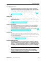
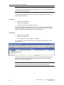
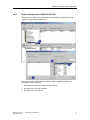
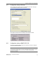
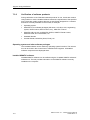
UPS configuration via digital inputs
In addition to the standard buffering provided by UPS devices, the option of
monitoring the power supplies should be used. In this case, the phase is monitored
via one or several digital inputs. The failure of the energy supply can be registered
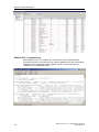
via alarm messages and archived during production in the batch report. This
guarantees a complete record of the plant problems.
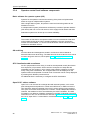
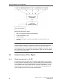
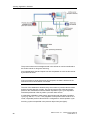
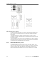
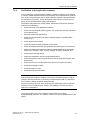
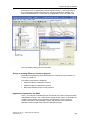
UPS buffering of load voltage
The automation CPU is supplied with power by the UPS 24 V module both during
voltage dips and longer power failures. The phase monitoring module monitors the
status change during a power failure using a digital input that should be designed
as a fail-safe input signal. If a power failure occurs, an additional alarm can be
generated to inform the operator of the power failure (alarm message). By logging
it in the message system, this power failure can be used for subsequent investigations.
With power failure concepts, safe states can also be implemented immediately or
after a certain delay (for example, equipment phase hold, establishing a safe plant
status even after power has returned, etc.).
SIMATIC PCS7 V7.1 - GMP Engineering Manual
A5E02795571-01
107