1
WE DO FUTURE
User Manual
Ver. 1.2 [62]
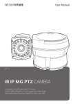
IR PTZ CAMERA
The World s First 360 Endless PAN/ TILT Motion
Auto LED Brightness Control by Distance Range
Auto LED Pulse Control by Distance Range
PAN/ TILT Torque Compensation (Step-Out Prevention)
Contents
CONTENTS-----------------------------------------------------------------------------------------------------------------------COMPONENTS-------------------------------------------------------------------------------------------------------------------WARNINGS & CAUTIONS-------------------------------------------------------------------------------------------------------GENERAL FEATURES--------------------------------------------------------------------------------------------------------------
2
2
3
6
PART NAMES---------------------------------------------------------------------------------------------------------------------A. Basic Parts------------------------------------------------------------------------------------------------------------------B. Connection Method--------------------------------------------------------------------------------------------------------INSTALLATION-------------------------------------------------------------------------------------------------------------------A. Ceiling Mount Bracket------------------------------------------------------------------------------------------------------B. Pole Stand------------------------------------------------------------------------------------------------------------------C. Wall Mount Bracket--------------------------------------------------------------------------------------------------------QUICK OPERATING KEYS--------------------------------------------------------------------------------------------------------DIAGNOSTIC---------------------------------------------------------------------------------------------------------------------OSD MENU SETTING------------------------------------------------------------------------------------------------------------A. OSD Menu Table-----------------------------------------------------------------------------------------------------------B. Dome Set-------------------------------------------------------------------------------------------------------------------C. Camera Set-----------------------------------------------------------------------------------------------------------------D. Preset Set-------------------------------------------------------------------------------------------------------------------E. Auto Scan Set---------------------------------------------------------------------------------------------------------------F. Tour Set----------------------------------------------------------------------------------------------------------------------G. Privacy Set------------------------------------------------------------------------------------------------------------------H. Pattern Set------------------------------------------------------------------------------------------------------------------I. Alarm Set--------------------------------------------------------------------------------------------------------------------J. Sector Set-------------------------------------------------------------------------------------------------------------------DIP SWITCHING SETTING-------------------------------------------------------------------------------------------------------A. ID Setting-------------------------------------------------------------------------------------------------------------------B. 485 Termination------------------------------------------------------------------------------------------------------------C. Protocol---------------------------------------------------------------------------------------------------------------------D. Baud Rate Setting----------------------------------------------------------------------------------------------------------TROUBLESHOOTING-------------------------------------------------------------------------------------------------------------SPECIFICATION-------------------------------------------------------------------------------------------------------------------DIMENSIONS----------------------------------------------------------------------------------------------------------------------
7
7
8
9
9
11
13
15
17
18
18
19
25
27
28
29
30
31
33
34
35
35
41
41
41
42
43
44
Components
1. IR CAMERA 1SET
2. MANUAL 1EA
Warnings & Cautions
• If you fail to read this information and handle the product incorrectly, death or serious injury may
occur.
• The unit should be installed by trained personnel.
• Switch off immediately if the product emits smoke or abnormal heat.
• Never install the product in an area with exposed oil or gas.
• Never install the product on a ceiling that cannot hold its weight.
• Never touch the power cord with wet hands. Clean only with dry cloth.
• Never install the product in extreme high or low temperature.
• Never drop, hit strongly or cause the product to vibrate.
• Never expose the product to direct sunlight or severe ray.
This symbol is intended to alert the user to the presence
of un-insulated dangerous voltage within the product s
enclosure that may be of sufficient magnitude to
constitute a risk of electric shock to persons.
This symbol is intended to alert the user to the presence
of un-insulated dangerous voltage within the product s
enclosure that may be of sufficient magnitude to
constitute a risk of electric shock to persons.
General Features
• IR LED PTZ has been designed unique and strong with high quality for security applications that
demand the very high performance both day and at night time.
• The range offers numerous benefits over the use of traditional dome and PTZ cameras, and
comes with a variety of options in order to offer a best fit solution for virtually any application.
• Rated to an industry leading IP68, the vandal resistant aluminum camera housing is suitable for
installation in the harshest of environments.
• Surveillance with optimum picture is possible owing to filter changeable Day & Night function
and DSS function.
• Auto-IR cut filter removable function is the auto-controlling operation such as color picture plus
infrared cut filter during the day and black and white picture plus filter elimination at night.
THE WORLD'S FIRST 360 ENDLESS PAN/TILT MOTION
• IR PTZ camera adopted the world's first 360 endless Pan / Tilt.
AUTO LED BRIGHTNESS CONTROL BY DISTANCE RANGE
• When it's on a wide angle(zoom out), illumination level of LED is automatically readjusted to a
dimmer level by way of prevention against image saturation. When it's on a narrow angle(zoom
in), illumination level of LED is automatically readjusted to get the maximum to have enough
light for clear image display and reduction of energy consumption.
(30
LED 28EA, 12
LED 15EA)
PAN / TILT TORQUE COMPENSATION
• Pan / Tilt Torque vibration sensor keeps the Pan / Tilt Motor securely in place during strong
winds.
AUTO LED PULSE CONTROL BY DISTANCE RANGE
• It automatically controls the pulse of LED electric current which is consumed Most depending on
distance range so that it produces 2 times better LED Brightness with same amount of electric
current as others.
Part Names
A. Basic Parts
Part Names
B. Connection Method
ⓐ Explanation
Color
Black
BNC
USE
Video Cable
ⓑ Explanation
Color
YELLOW
BROWN
RED
WHITE
WHITE
VIRMILION(ORANGE)
VILOET
PINK
SKY BLUE
BLACK
BLUE
GREEN
USE
(AWG#20)
AUX 1-A
AUX 1-B
AUX 2-A
AUX 2-B
GND
ALARM 1
ALARM 2
ALARM 3
ALARM 4
GND
RS-485 D+
RS-485 D+
ⓒ Explanation
Color
RED
WHITE
BLACK
Installation
A. Ceiling Mount Bracket
COMPONENTS
1. CEILING MOUNT BRACKET 1EA
2. SET ANCHOR BOLT (W5/9) 4EA
3. SCREW M4 x 16 5EA
4. SPRING WASHER Ø4 5EA
5. WRENCH (3mm) 4EA
6. MANUAL
USE
AC 24
AC 24
F. G.
A-1. When you install IR PTZ Camera on the ceiling, make 4 holes at the edge with Ø13 in
diameter and 37mm in depth. If you want to connect the cables from the inside of the ceiling, also
make a ole for the cables with about Ø30~50 in diameter in the center of 4 edges. (FIG.1)
A-2. Connect the Ceiling Mount Bracket to the Camera with 4 pieces of M4X16 screws and spring
washer. (FIG.2)
A-3. Connect the Safety wire of the Camera to the Bracket. In order to avoid getting entangled in
the Camera, fasten the Safety wire to the bracket with Cable tie. (FIG.3)
Installation
A-4. When you want to connect the cables from the inside of ceiling, pass the cables through the
ceiling. When you want to connect the cables from the outside of ceiling, remove the hole cap from
the side of the bracket and pass the cables through the hole.
A-5. Install 4 pieces of Anchor bolt in the holes at the edge and tight enough with Nuts. (FIG.4)
A-6. Connect the cables referring to the page 8. (FIG.5)
Installation
B. Pole Stand
COMPONENTS
1. POLE STAND 1EA
2. BOLT M10 x 45 4EA
3. NUT M10 4EA
4. FLAT WASHER 4EA
5. SPRING WASHER Ø10 4EA
6. SCREW M4 x 16 5EA
7. SPRING WAHGER Ø4 5EA
8. WRENCH (3mm) 1EA
9. MANUAL
B-1. When you install IR-PTZ Camera on the pole, make 4 holes at edge with Ø13 in diameter and
37mm in depth. Make also a hole for the cables with about Ø30~50 in diameter in the
bottom center of the bracket. (FIG.6)
B-2. Pass the cables of the camera through the inside of Pole Stand and connect the Camera to
the Pole Stand with pieces of M4*16 screws. (FIG.7)
B-3. Connect the Safety Wire of the camera to the bracket. In order to avoid getting entangled in
the camera, fasten the Safety wire to the bracket with Cable Tie. (FIG.8)
Installation
B-4. Install 4 pieces of Anchor bolt in the Ø13 holes at the edge and connect the cables.
B-5. Adjust the Camera and Pole Stand to M10 x 45 Bolt and Flat Washer, Spring Washer. And
then tight enough with Nuts. (FIG.10)
Installation
C. Wall Mount Bracket
COMPONENTS
1. WALL MOUNT BRACKET 1EA
2. SET ANCHOR BOLT (W5/6) 4EA
3. SCREW M4 x 16 5EA
4. SPRING WASHER Ø4 5EA
5. WRENCH (3mm) 1EA
6. MANUAL
C-1. When you install IR PTZ Camera on the wall, make 4 holes at the edge with Ø13 in diameter
and 37mm in depth and install 4 pieces of Anchor bolt in the Ø13 holes at the edge. (FIG.11)
• If you want to connect the cables from the inside of the wall, also make a hole for the cables
with about Ø30~50 in diameter in the center of 4 edges.
• In order to avoid the impact of the Camera and Bracket when moving, set and drill in the long
side as length and the short side as height.
• Check also if the long side of the Bracket sets as length and the short side of the Bracket sets
as height.
C-2. Connect the Camera to Wall Mount Bracket with 4 pieces of M4 x 16 screws and Spring
Washer. (FIG.12)
Installation
C-3. Connect the Safety wire of the Camera to the Bracket. In order to avoid getting entangled in
the Camera, fasten the Safety wire to the bracket with Cable tie. (FIG.13)
C-4. When you want to connect the cables from the inside of wall, pass the cables through the wall.
When you want to connect the cables from the outside of wall, remove the hole cap from the side
of the bracket and pass the cables through the hole.
C-5. Install 4 pieces of Anchor bolt in the holes at the edge and tight enough with Nuts. (FIG. 13)
C-6. Connect the cables referring to the page 8. (FIG.14)
Quick Operating Keys
The IR Camera supports Pelco D/P Protocols
The default setting of the IR Camera is Pelco D/P(Auto Detection) with 2400bps (Baud rate).
[PELCO D/P PROTOCOLS]
The comprehensive feature set of the camera is available from Pelco Compatible controllers via
quick operation keys as defined below. 1 ~ 64 + preset and 100 ~ 200 + preset are used for
normal user presets. Presets 65 ~ 99 + are reserved for special functions. For Example, to enter
OSD MENU, press the button 95 + Preset.
<Quick Operation Key Table 1>
Number
1 ~ 64, 100 ~ 200 + PRESET
65 + PRESET
66 + PRESET
70 + PRESET
71 ~ 78 + PRESET
81 ~ 88 + PRESET
91 + PRESET
92 + PRESET
93 + PRESET
94 + PRESET
95 + PRESET
96 + PRESET
97 + PRESET
98 + PRESET
99 + PRESET
Note
Preset
Preset Status
Auto Scan
VIB CORR
Group Tour
Pattern
Zero Position
Freeze
BLC
Day/Night
OSD
Focus Adjust
Alarm
AUX1
AUX2
Function
Executing Preset 1 ~ 64, 100 ~ 200
Display Preset Status
Executing Auto Scan
Selectable On / Off in picture Stabilization Function
Executing Group Tour #1 ~ #8
Executing Pattern #1 ~ #8
Searching Pan / Tilt Zero Position
Select Freeze image when camera is working
Selectable On / Off BLC function
Selectable Day / Night / Auto Mode
Entering OSD Main Menu
Focus adjust
Selectable Enable / Disable all alarms
Selectable On / Off Aux1
Selectable On / Off Aux2
<Quick Operation Key Table 2>
Number
1 ~ 64, 100 ~ 200 + PRESET
65 + PRESET
66 + PRESET
70 + PRESET
Function
Sub menu cursor moves up / down
Enter to the sub menu or status change or decrement
Using for enter key when user select YES or NO
Using for function changing keys when set coordinate
71 ~ 78 + PRESET
81 ~ 88 + PRESET
Status cursor to the right
Status cursor to the left
Quick Operating Keys
• 65 + Preset
Preset Status is displayed, to remove this screen, Press Focus Near button.
• 92 + Preset
This feature freezes the current live image during tour, auto scan or pattern operation.
When you press 92+Preset button, the image freezes but the camera is still working as
operation such as tour, pattern or auto scan. To return to normal images, press 92+Preset
button again
• This feature is operated by preset number but not included in OSD main menu.
• Due to Zoom camera module. OSD Menu not provides every feature. In this case,
available is displayed on the monitor.
Diagnostic
Whenever the IR Camera is power on, a standard diagnostic is operated.
Not
A. PAN Origin Test
Zero point of Pan is Located during the Panning test.
B. Tilt Origin Test
Zero point of Tilt is Located during the Tilt Test
C. TX Connection Test
Wait for 60 seconds for TX Connection Test.
During 60 seconds, the camera is must received a signal by any control equipment as DVR or
controller. Then OK is displayed then automatically verifying TX Connection Test
• If Not Tested
is displayed in the test.
- The result which is not received any signal from DVR or controller.
- Wrong connecting way such as the protocol, baud rate or RS-485 connection.
The use may check the install way carefully.
D. Camera Comm. Test
Camera communication is also checked.
OK should be displayed in these four tests before installation.
If all the above Tests are OK, NOW EEPROM CHECKING and
INITIALIZING is displayed and the camera is ready to operate.
OSD Menu Setting
A. OSD Menu Table
ALL DATA
OSD Menu Setting
To enter OSD Menu, press the button 95+Preset then OSD Main Menu is displayed.
• Use the joystick up down to move the position and left right to make selection.
B. Dome Setup
To enter dome setup, use the joystick right to move when cursor on dome setup.
B-1. DOME SET - CAMERA ID
To set camera name, and select a title of up to 16 characters using left or right direction keys or
joystick. Press ZOOM TELE button to move to the next character from left to right direction and
ZOOM WIDE button to move to the next character from right to left direction. (Space displays
when □ appears.)
B-2. DOME SET - HOME POS
This is for Home Position, basically, including the Recover. On ON, it would be indicated the
number [Relevant function], number is for time and [Relevant function] is that what operation
product will be working on. You can set up the time using the Joystick Left/Right, it should be
showed up on the Left of Menu if you press the Focus Far Key. In case of [ ] , possible to
change into other one as you want and come out from [ ] after vanish.
OSD Menu Setting
- Set time : 15~90 (Each 5)
- Set article : [AUTO] - RECOVER operation.
[PRST1]-[PRST8] ‒ PRESET1 ~ PRESET8 OPERATION.
[TOUR1] ~ [TOUR8] ‒ TOUR1 ~ TOUR8 OPERATION.
[PATT1] ~ [PATT8] ‒ PATTERN1 ~ PATTERN8 OPERATION
[SCAN] ‒ AUTOSCAN OPERATION.
B-3. DOME SET - MANUAL SPEED
Manual speed of Pan / Tilt is selectable from 100˚/sec up to 200˚/sec.
he default setting is 150˚/sec.
B-4. DOME SET - ZOOM SPEED
Move joystick right or left direction is selectable from SLOW ~ FAST.
The default setting is FAST.
B-5. DOME SET - ALARM
You must enable the alarms for them to operate. The default setting is disabled.
This function can be recalled by pushing 97+preset button.
B-6. DOME SET ‒ LANGUAGE
Multiple languages are selectable here including English, Italian and Polish.
The default setting is ENGLISH.
B-7. DOME SET - [NEXT PAGE]
OSD Menu Setting
B-7-1. DOME SET - [NEXT PAGE] -SYSTEM SET
To enter system set, use the joystick right to move when cursor on system set.
- Flip status available and the default setting is NORMAL.
Move joystick right or left direction is for selecting NORMAL or REVERSE.
- Motor torque available and the default setting is LOW.
Move joystick right or left direction is for selecting LOW or MIDDLE or HIGH.
- Recover Origin is for correct when both of PAN and TILT are warped by impact.
On ON, it should be operated, on OFF, it's not.
- D/N Level is selectable 0 to 15. The default setting is 08.
- Temperature available and the default setting is CELSIUS.
Move joystick right or left direction is for selecting CELSIUS or FAHRENHEIT.
B-7-2. DOME SET - [NEXT PAGE] -SYSTEM LOCK
All stored dome settings can be password protected to prevent unauthorized changes. In order to
enter [PASSWORD] page, the system lock status must firstly be set as ON. The default setting is
OFF.
B-7-3. DOME SET - [NEXT PAGE] -[PASSWORD].
To enter this page to set a password. move joystick or pan key in the right direction.
The password must be set by preset number from 001 to 255 (Default 99).
OSD Menu Setting
Enter any number from 001~255 on the password blank area and again on the confirm blank area.
Then
CONFIRMED
is displayed on the monitor and the menu will go back to the previous
age automatically.
If you press an incorrect number between PASSWORD and CONFIRMED,
CANCELLED is displayed on the monitor when you press FOCUS NEAR key.
CANCELLED will be displayed on the monitor, it goes to previous page.
• When a password has been set, the operator must enter the correct password in order to enter
OSD MAIN MENU, or to change any of the domes configuration data.
• If you set a password you must ensure that it does not get lost. If this happens the dome must
be returned for workshop repair.
B-7-4. DOME SET - [NEXT PAGE] - [OSD DISPLAY]
The camera ID setting defines whether the camera OSD display is displayed or switched off.
B-7-5. DOME SET - [NEXT PAGE] - [SYSTEM STATUS]
This page shows the information of this camera.
- Protocol and baud rate are shown due to the dip switch setting
- Firmware version and upgraded date will change if upgraded.
- Camera module is setting as follows.
OSD Menu Setting
B-7-6. DOME SET - [NEXT PAGE] - [INITIALIZATION]
To clear the current settings select the item that you wish to reset back to factory defaults.
To clear the memorized data. move the joystick or pan right key until the cursor is on the required
item.
Press FOCUS NEAR button when the cursor is at YES in order to clear memorized data.
Then each item such as tour, preset, and sector will flicker for about 2 ~ 3 seconds.
After this process, the menu is returned to the previous page.
• Use the above method for [PRESET CLEAR], [SECTOR CLEAR],[PRIVACY CLEAR],
[PATTERN CLEAR].
OSD Menu Setting
- To Clear all data and return to factory defaults, move the joystick right or press the pan light key
to when the cursor is at [LOAD OPTIMIZED DEFAULT] to enter the next page.
- Move joystick or the pan right key so that the cursor is over YES, then press the FOCUS NEAR
button.
ALL DATA INITIALIZING is then displayed for about 5~7 seconds and then the menu is
returned to the previous page automatically.
B-8. DOME SET - [NEXT PAGE] - SAVE AND EXIT
To saving the memorized data and escape this page, move joystick to the right direction when
cursor is at SAVE AND EXIT.
B-9. DOME SET - [NEXT PAGE] ‒ EXIT
In order not to save any data and wants to escape this page, move joystick to the right direction
when cursor is at EXIT.
OSD Menu Setting
C. Camera Set
C-1. CAMERA SET - FLICKERLESS
The flickerless feature has options of 50Hz and 60Hz.
The default setting is OFF (NTSC : 60Hz / PAL : 50Hz).
The flickerless mode only needs to be set when there is a mismatch between the power frequency
and camera sync rate. The default setting is OFF.
C-2. CAMERA SET - SHUTTER
It is for set up the Shutter Speed of camera.
•Default value is Auto and it can be changed into other one using the Joystick Left/Right of
Controller.
- Change to turn : Full Auto → Manual
- Auto : Changed according to light level automatically.
- Manual : It can be changed into other one using the Focus Far Key of
controller and on ON the DSS (Digital Slow Shutter), it should be set up 1/1 to 1/10,000, on OFF,
1/50(1/60)~1/10,000.
C-3. CAMERA SET - APERTURE
Aperture correction enhances the picture details and sharpness by increasing the gain of the
camera. Increase the value to sharpen the image, decrease to soften it the default setting is 10.
(The aperture level is from 01 ~ 15.)
C-4. CAMERA SET - D ZOOM
Digital zoom is enabled to apply when the zoom lens has reached its maximum optical zoom in
capability. The default setting is OFF.
OSD Menu Setting
C-5. CAMERA SET - WB MODE
White balance functions has 4 modes and may need to be changed depending on the situation.
• AWB Mode : 3,200ºK to 6,500ºK (Default)
• Indoor : up to 3,200ºK
• Outdoor : up to 5,800ºK
C-6. CAMERA SET - BLC (Back Light Compensation)
From simple ON / OFF setting to user friendly BLC status indication [BLC] status with control of
controller by "FOCUS FAR KEY"(" " signal appeared)
With the control of joystick on controller by LEFT / RIGHT, setting change of [BLC] / [WDR] is
available.
Setting change completed by pressing FOCUS FAR KEY.(" " signal disappeared.) This function
can be recalled by pushing 93+Preset button.
C-7. CAMERA SET - D/N MODE
The dome camera can operate in day / night mode and will switch depending on lighting
conditions. Alternatively it can be forced into color only mode.
The default setting is AUTO MODE. This function can be recalled by pushing 94+Preset button.
C-8. CAMERA SET - DSS MODE (DIGITAL SLOW SHUTTER)
If digital slow shutter is enabled the exposure time of the camera is increased, thus allowing more
light to be collected and improving low light response.
This setting should not be enabled if the dome is touring at night or fast moving objects are likely
to be in the scene as smearing is also increased. The default setting is OFF.
C-9. CAMERA SET - [NEXT PAGE] - HR MODE
Images with a high resolution can be obtained using a newly developed DSP for improved picture
quality. The default setting is OFF.
• OFF : 530TV Lines • ON : 550TV Lines
C-10. CAMERA SET - [NEXT PAGE] - DNR MOED
It enables noise reduction digitally.
It sets the noise reduction rate using LEFT / RIGHT key of CONTROLLER JOYSTICK [OFF, 1~5].
The default setting is OFF
C-11. CAMERA SET - [NEXT PAGE] - IS MODE
It help to stabilized video image when camera revealed to wind or other environmental reasons.
The default setting is OFF.
OSD Menu Setting
D. Preset Set
D-1. PRESET - PRESET NO
Up to 165 preset positions are available.
Use the joystick or pan left / right keys to select the number.
D-2. PRESET - PRESET ID
To create preset titles use the joystick or pan left / light keys to navigate the menu.
The ZOOM TELE button moves to the next character from left to right and ZOOM WIDE button
moves to the next character from right to left. (Space displays when □ appears.)
D-3. PRESET - PAN : XXX.X TILT : XX.X
Preset FOCUS FAR button in order to set preset position then, use the joystick or pan left / right
keys to the position where memorized preset number is needed.
Then press FOCUS FAR button again after setting a preset location.
D-4. FREEZE MODE : On Preset, you make a decision whether you get it move or stop.
On ON, Freeze Preset can be working on.
D-5. FREEZE ALL : You can set it up into ON / OFF, on ON, Freeze all should be working on.
D-6. PRESET - SAVE
Move the joystick right or press the pan right key when the cursor is at SAVE and then the cursor
will be located on Preset ID for the continuous preset No. setting.
D-7. PRESET ‒ EXIT
To escape this page, move joystick to the right direction.
OSD Menu Setting
E. Auto Scan Set
66+Preset button is working as AUTO SCAN after setting.
E-1. AUTO SCAN - START ANGLE.
To set the start position, press FOCUS FAR button then move the dome to the required start
position. Press FOCUS FAR button again is to escape.
E-2. AUTO SCAN - END ANGLE
To set the end position, press FOCUS FAR button then move the dome to the required end
position. Press FOCUS FAR button again is to escape.
E-3. AUTO SCAN - DIRECTION
Auto Scan directions are available as CW or CCW.
• CW : Clock wise direction. [Default]
• CCW : Count Clock Wise Direction.
E-4. AUTO SCAN - ENDLESS
Auto Scan can be set to endless rotation by enabling the endless option. The default setting is
OFF.
E-5. AUTO SCAN ‒ SPEED
The scan speed can be programmed from 05 /S up to 35 /S.
The default setting is 10 /S.
E-6. AUTO SCAN - DWELL TIME
The dwell time at the start and end points can be programmed from 1 second to 30 seconds. The
default setting is 03 seconds.
E-7. AUTO SCAN - SAVE AND EXIT
To save the memorized data and escape this page, move the joystick right or press the pan right
key when the cursor is at SAVE AND EXIT.
E-8. AUTO SCAN - EXIT
To escape this page, move joystick to the right direction.
OSD Menu Setting
F. Tour Set
8 Programmable tours can be set and each tour can have up to 64 preset steps. After setting up
the tours the 71 ~ 78+Preset buttons launch group tours #1 ~ 8.
F-1. TOUR SET - TOUR NO.
Up to 8 group tours can be programmed.
F-2. TOUR SET - TOUR TITLE
To set a tour title, use the joystick left / right or pan left / right keys. Each title can have up to 16
characters. Press ZOOM TELE button to move the next character from left to the right and ZOOM
WIDE button to move the next character from right to left. (Space displays when □ appears.) The
tour title is not displayed on the monitor and is only for the reference of user.
F-3. TOUR SET - TOUR STEP
Each tour group consists of up to 60 preset steps with different dwell time and speed.
It is possible to match any preset # for any tour step.
F-4. TOUR SET- PRESET NO.
For each tour step it is possible to select any preset number up to 64. The default setting is BLK.
F-5. TOUR SET - DWELL TIME
Dwell time can be programmed from 1-99 seconds. The default setting is 03 seconds.
F-6. TOUR SET ‒ SPEED
Each tour step can be set with a different speed up to 200 /S.
F-7. TOUR SET - SAVE
To save the memorized data and escape this page, move the joystick right or press the pan right
key when cursor is at SAVE.
F-8. TOUR SET - EXIT
To escape this page, move joystick to the right direction.
OSD Menu Setting
G. Privacy Set
8 Privacy masking zones can be set.
G-1. PRIVACY SET - PRIVACY NO.
Up to 8 privacy masking zones can be set.
G-2. PRIVACY SET - DISPLAY
Move the joystick right or left or press pan right / left to set ON in order to show the selectable
block in the center of the monitor. This block appears as a translucent square with blue color when
set ON. The default setting is OFF.
G-3. PRIVACY SET - ACTION (MOVE / ADJUST)
To set the blocking area, press FOCUS FAR button when MOVE MODE is displayed.
Then use the joystick or pan keys to the user defined area in order to set the blocking area.
Then press FOCUS FAR button again to escape from Move mode. To adjust the size of the
blocking area, move the joystick or use the pan keys when the cursor is on ACTION. After it has
changed to ADJUST MODE, press FOCUS FAR button in order to adjust the size of the blocking
area. The size of the blocking area can be adjusted by using joystick up / down or left / right or the
pan and tilt keys.
After adjusting the size of the blocking area, press FOCUS FAR button to escape the ADJUST
mode
• ADJUST : You can change the masking size by using the joystick or pan keys.
• MOVE : You can move the masking area by using the joystick or pan keys. (Default)
OSD Menu Setting
G-4. PRIVACY SET - SAVE.
After setting the privacy masking zone, to save the data, move the joystick right or pan right key
when the cursor is on SAVE.
After saving the data, the cursor moves to PRIVACY NO.2 automatically to prepare for the next
privacy masking zone.
G-5. PRIVACY SET ‒ EXIT
To escape this page, move the joystick right.
H. Pattern Set
8 Programmable patterns are available with 16 characters of title.
After set the data to the each pattern #1 ~ 8, 81 ~ 88+preset buttons are working as pattern #1 ~ 8.
H-1. PATTERN SET - PATT NO.
Up to 8 Programmable user-defined patterns are available.
H-2. PATTERN SET - PATT TITLE.
To set PATTERN TITLE move Joystick left / right or use the pan keys. Press ZOOM TELE button
moves to the next character from the left / right and ZOOM WIDE button moves to the next
character from the right / left. (Space displays when □ appears.)
The pattern title is not displayed on the monitor, but only for the reference of the user.
H-3. PATTERN SET - DATA FILL
To memorize a pattern, press FOCUS FAR button in order to start the process. The progress is
shown as % filled. Press FOCUS FAR button again in order to escape.
OSD Menu Setting
H-4. PATTERN SET - SAVE
To save the memorized pattern data, move the joystick right or press the pan right key when the
cursor is on SAVE. Then the cursor moves to the PATT NO.02 in order to prepare for the next
pattern.
H-5. PATTERN SET - EXIT
To escape this page, move the joystick right or press the pan right key.
OSD Menu Setting
I. Alarm Set
4 Alarm inputs are available and each alarm is activating to presets, group tours or patterns.
I-1. ALARM SET - ALARM NO.
Up to 4 alarms are selectable by using joystick right or pressing the pan right key when the cursor
is on ALARM NO.
I-2. ALARM SET - ALARM INPUT
Alarm inputs can be programmed as NC (Normally Close) or NO (Normally Open).
The default setting is OFF.
I-3. ALARM SET - ALARM ACT
Active alarms can trigger modes such as presets, Group tours 1-8, and Patterns 1-8.
Use the joystick or pan keys to select any preset number, Group tour No.
I-4. ALARM SET - AUX ACT
You can select one of BLK (No AUX triggering) / AUX1 (triggering AUX1) / AUX2 (triggering AUX2)
and default value is BLK.
If ALARM triggers AUX, AUX will be off after 5 seconds. If many ALARMs trigger AUX port one by
one, the last one will be off after 5 seconds.
I-5. ALARM SET - SAVE
After setting up the alarm features, to save the data move the joystick right or press the pan right
key when the cursor is on SAVE. After saving the data, the cursor moves to Alarm NO.2
automatically to prepare for the next alarm.
I-6. ALARM SET - EXIT
To escape this page, move the joystick right or press the pan right key.
• Before activating Alarms, you must set ALARM ENABLE at DOME SET ALARM ENABLE.
J. Sector Set
Up to 8 programmable sectors are available with 16 characters.
This feature is useful to memory the certain location such as parking zone or so on.
J-1. SECTOR SET - SECTOR NO.
Up to 8 programmable sectors are available.
J-2. SECTOR SET - SECTOR ID
To set a SECTOR ID, use the joystick or pan left /right keys.
Press ZOOM TELE button to move to the next character from left to right and ZOOM WIDE button
to move to the next character from right to left. (Space
displays when □ appears.)
J-3. SECTOR SET - SECTOR START
To set a SECTOR START position press FOCUS FAR button then move the joystick or pan keys
to set the position. Press FOCUS FAR button again to escape.
J-4. SECTOR SET - SECTOR END
To set a SECTOR END position press FOCUS FAR button then move the joystick or pan keys to
set the position. To press FOCUS FAR button again to escape.
J-5. SECTOR SET - SAVE
After setting the SECTOR position, to save the data move the joystick right or press the pan right
key when the cursor is on SAVE. After saving the data, the cursor moves to sector No. 2
automatically to prepare for the next sector.
J-6. SECTOR SET ‒ EXIT
To escape this page, move joystick to the right or press the pan right key.
K. Exit
To escape OSD Main Menu, move joystick to the right or left direction then this
camera is ready to operate.
Dip Switch Setting
A. ID Setting
The camera has camera ID to be controlled by controller or DVR. After opening, set ID using DIP
SW1.
• Factory default : Camera ID = 1
Dip Switch Setting
Dip Switch Setting
Dip Switch Setting
Dip Switch Setting
Dip Switch Setting
Dip Switch Setting
B. 485 Termenation
The 8th of DIP SW2 is used for 100Ω termination.
Set ON DIP SW2-1st of only the last looped camera from the controller.
C. Protocal
The 4th, 5th of DIP SW2 above are used for protocol setting.
• Factory default : Pelco-D or Pelco-P (Auto detection)
D. Baud Rate Setting
DIP SW2 - 4th, 5th
DIP SW2 - 4th
OFF
OFF
ON
ON
DIP SW2 - 5th
ON
OFF
ON
OFF
BAUD RATE
Pelco-D or Pelco-P
Not used
Not used
Not used
The 7th, 8th SW of DIP SW2 above a used for BAUD RATE setting. DIP SW can be
changeable to 4,800bps, 9,600bps.
• Factory default : 2,400bps
DIP SW2 - 1st
OFF
ON
OFF
ON
DIP SW2 - 2nd
OFF
OFF
ON
ON
BAUD RATE
2,400bps
4,800bps
9,600bps
Not used
• The 3th, 6th, 7th of DIP SW2 are not used.
Trouble Shooting
If you have trouble setting up or operating the camera, refer to the following.
Problem
NO OPERATION
NO PICTURE
DARK SCREEN
ABNOMAL CAMERA
OPERATION STATUS
SCREEN NOT CLEAR
•
•
•
•
•
•
•
•
•
•
•
•
•
•
Solution
Check if the power supply is AC 24V.
Check if RS-485 communication cable is connected correctly.
Check camera ID setting.
Check the termination.
Check if all the cables are connected correctly.
Check the monitor is adjusted correctly.
Check if video signal line is cut.
Adjust the monitor status.
Check if the voltage level is out of the specification.
Check the termination.
Check if there is dust on a lens.
Adjust the monitor status.
If excessive light is seen on a screen, change the camera angle or location.
Adjust the lens focus again.
Specification
Dimensions