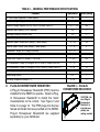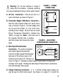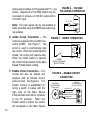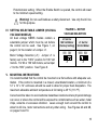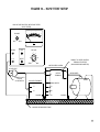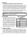
1
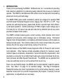
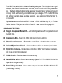
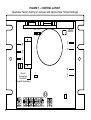
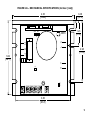
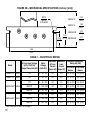
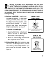
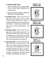
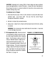
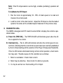
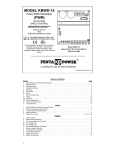
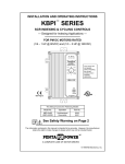
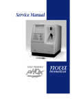
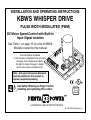
INSTALLATION AND OPERATING INSTRUCTIONS
KBWS WHISPER DRIVE
PULSE WIDTH MODULATED (PWM)
DC Motor Speed Control with Built-In
Input Signal Isolation
See Table 1 on page 10 for a list of KBWS
Models covered by this manual
The information contained
in this manual is intended to be accurate.
However, the manufacturer retains
the right to make changes in design
which may not be included herein.
Note: A PLug-In Horsepower Resistor®
must be installed for this product to
operate (supplied separately).
!
See Safety Warning on Page 5 before
installing and operating this control
Hi-Pot
Tested
1500 VAC
TM
A COMPLETE LINE OF MOTOR DRIVES
© 2001 KB Electronics, Inc.
TABLE OF CONTENTS
Section
Page
i.
Simplified Operating Instructions . . . . . . . . . . . . . . . . . . . . . . . . . . . . . . . . . . . . 4
ii.
Safety Warning . . . . . . . . . . . . . . . . . . . . . . . . . . . . . . . . . . . . . . . . . . . . . . . . . 5
I.
Introduction . . . . . . . . . . . . . . . . . . . . . . . . . . . . . . . . . . . . . . . . . . . . . . . . . . . . 6
II.
Plug-In Horsepower Resistor® . . . . . . . . . . . . . . . . . . . . . . . . . . . . . . . . . . . . . 11
III. Wiring Instructions . . . . . . . . . . . . . . . . . . . . . . . . . . . . . . . . . . . . . . . . . . . . . . 12
IV. Setting Selectable Jumper (On Dual Voltage Models) . . . . . . . . . . . . . . . . . . . 15
V. Mounting Instructions . . . . . . . . . . . . . . . . . . . . . . . . . . . . . . . . . . . . . . . . . . . . 15
VI. Recommended High Voltage Dielectric Withstand Testing (Hi-Pot Testing) . . . . 16
VII. Operation . . . . . . . . . . . . . . . . . . . . . . . . . . . . . . . . . . . . . . . . . . . . . . . . . . . . 18
VIII. AC Line Fusing . . . . . . . . . . . . . . . . . . . . . . . . . . . . . . . . . . . . . . . . . . . . . . . . 18
IX. Trimpot Adjustments . . . . . . . . . . . . . . . . . . . . . . . . . . . . . . . . . . . . . . . . . . . . 18
X. Diagnostic LEDs . . . . . . . . . . . . . . . . . . . . . . . . . . . . . . . . . . . . . . . . . . . . . . . 22
XI. Optional Accessories . . . . . . . . . . . . . . . . . . . . . . . . . . . . . . . . . . . . . . . . . . . . 23
XII. Limited Warranty . . . . . . . . . . . . . . . . . . . . . . . . . . . . . . . . . . . . . . . . . . . . . . . 24
Tables
1.
Electrical Ratings . . . . . . . . . . . . . . . . . . . . . . . . . . . . . . . . . . . . . . . . . . . . . . . 10
2.
General Performance Specifications . . . . . . . . . . . . . . . . . . . . . . . . . . . . . . . . 11
3.
Plug-In Horsepower Resistor® Selection . . . . . . . . . . . . . . . . . . . . . . . . . . . . . 12
4.
Recommended AC Line Fuse . . . . . . . . . . . . . . . . . . . . . . . . . . . . . . . . . . . . . 18
ii
Figures
1.
Pages
Control Layout . . . . . . . . . . . . . . . . . . . . . . . . . . . . . . . . . . . . . . . . . . . . . . . . . . 8
2A. Mechanical Specifications . . . . . . . . . . . . . . . . . . . . . . . . . . . . . . . . . . . . . . . . . 9
2B. Mechanical Specifications . . . . . . . . . . . . . . . . . . . . . . . . . . . . . . . . . . . . . . . . 10
3.
Plug-In Horsepower Resistor® . . . . . . . . . . . . . . . . . . . . . . . . . . . . . . . . . . . . . 11
4.
Power Connections . . . . . . . . . . . . . . . . . . . . . . . . . . . . . . . . . . . . . . . . . . . . . 13
5.
Main Speed Potentiometer Connection . . . . . . . . . . . . . . . . . . . . . . . . . . . . . . 13
6.
Voltage Following Connection . . . . . . . . . . . . . . . . . . . . . . . . . . . . . . . . . . . . . 14
7.
Inhibit Connection . . . . . . . . . . . . . . . . . . . . . . . . . . . . . . . . . . . . . . . . . . . . . . 14
8.
Enable Circuit Connection . . . . . . . . . . . . . . . . . . . . . . . . . . . . . . . . . . . . . . . . 14
9.
Motor Voltage Selection (J1) (Dual Voltage Models) . . . . . . . . . . . . . . . . . . . . . 15
10. Hi-Pot Test Setup . . . . . . . . . . . . . . . . . . . . . . . . . . . . . . . . . . . . . . . . . . . . . . 17
11. Maximum Speed Trimpot (MAX) Range . . . . . . . . . . . . . . . . . . . . . . . . . . . . . . 19
12. Minimum Speed Trimpot (MIN) Range . . . . . . . . . . . . . . . . . . . . . . . . . . . . . . . 19
13. Acceleration Trimpot (ACC) Range . . . . . . . . . . . . . . . . . . . . . . . . . . . . . . . . . 20
14. Deceleration Trimpot (DEC) Range . . . . . . . . . . . . . . . . . . . . . . . . . . . . . . . . . 20
15. Current Limit Trimpot (CL) Range . . . . . . . . . . . . . . . . . . . . . . . . . . . . . . . . . . 20
16. IR Compensation Trimpot (IR) Range . . . . . . . . . . . . . . . . . . . . . . . . . . . . . . . 21
iii
i.
SIMPLIFIED OPERATING INSTRUCTIONS
IMPORTANT – You must read these simplified operating instructions before proceeding. These instructions are to be used as a reference only and are not intended to
replace the detailed instructions provided herein. You must read the Safety Warning
on page 5 before proceeding. See Application Note, Section VII, on page 18.
A. Power Connection – Connect the AC line to L1 and L2 terminals, as shown in
Figure 4, on page 13 and as described in Section IIIA, on page 13.
B. Permanent Magnet (PM) Motor Connection (Two Wire Type) – Connect the
motor armature to terminals A+ and A- as shown in Figure 4, on page 13 and as
described in Section IIIB, on page 13. On dual voltage models, be sure that
Jumper J1 is set to the corresponding motor voltage position, as described in
Section IV, on page 15.
C. Plug-In Horsepower Resistor® – Install the proper Plug-In Horsepower
Resistor® (supplied separately) according to motor current and horsepower.
See Table 3, on page 12.
D. Trimpot Settings – All trimpots have been factory set, as shown in Figure 1, on
page 8. Trimpots may be readjusted, as described in Section IX, on page 18.
E. Diagnostic LEDs – After power has been applied, observe the LEDs to verify
proper control function, as described in Section X, on page 22.
This product complies with all CE directives pertinent at the time of manufacture. Contact the Sales Department for detailed installation and Declaration of
Conformity. Installation of a CE approved RFI filter (KBRF-300 [P/N 9484] or equivalent) is required. Additional shielded motor cable and/or AC line cables may also be
required.
4
ii.
!
SAFETY WARNING! Please read carefully
This product should be installed and serviced by a qualified technician, electrician,
or electrical maintenance person familiar with its operation and the hazards involved.
Proper installation, which includes wiring, mounting in proper enclosure, fusing or other
over current protection, and grounding can reduce the chance of electrical shocks,
fires, or explosion in this product or products used with this product, such as electric
motors, switches, coils, solenoids, and/or relays. Eye protection must be worn and
insulated adjustment tools must be used when working with control under power. This
product is constructed of materials (plastics, metals, carbon, silicon, etc.) which may
be a potential hazard. Proper shielding, grounding and filtering of this product can
reduce the emission of radio frequency interference (RFI) which may adversely affect
sensitive electronic equipment. If further information is required on this product, contact the Sales Department.
This control contains electronic Start/Stop circuits that can be used to start and
stop the control. However these circuits are never to be used as safety disconnects
since they are not fail-safe. Use only the AC line for this purpose.
Be sure to follow all instructions carefully. Fire and/or electrocution can result due
to improper use of this product.
This control does not contain protection circuitry to prevent full speed runaway in
the event of main power transistor failure. However, an optional Product Safety
Module (PSM) (P/N 9995) can be installed to prevent full speed runaway. If a PSM is
not used, the installer of this product should take proper precautions to include other
means, such as mechanical disconnects, warning notices, etc., to protect the operator
of the machine involved.
It is the responsibility of the equipment manufacturer and individual installer to supply this Safety Warning to the ultimate end user of this product. (SW effective 1/2001).
5
I.
INTRODUCTION
Thank you for purchasing the KBWS. KB Electronics, Inc. is committed to providing
total customer satisfaction by producing quality products that are easy to install and
operate. The KBWS is manufactured with surface mount components incorporating
advanced circuitry and technology.
The KBWS PWM (pulse width modulated) controls are designed to operate PWM
and SCR rated Permanent Magnet motors ranging from 1/50 HP to 11⁄2 HP. They
operate at a switching frequency greater than 16 kHz to provide high motor efficiency and quiet operation. Another advantage of PWM is higher output voltage (up to
130 Volts DC for 115 Volt AC line and 220 Volts DC for 208/230 Volt AC line) which
provides increased motor speed.
The KBWS contains pulse-by-pulse current sensing, which provides short circuit
protection and prevents control damage due to commutator arcing. Permanent
magnet motor demagnetization is completely eliminated because current peaks are
reduced to safe levels. The controls contain an AC inrush current limiter (ICL) which
reduces the AC line surge current during cycling of the AC line.
Standard features of the KBWS include diagnostic LEDs for Power On and Current
Limit indication. Other features include adjustable trimpots for maximum speed,
minimum speed, acceleration, deceleration, current limit and IR compensation. Also
provided is a connector for an Inhibit Switch and quick-connect terminals for AC line,
motor armature and Main Speed Potentiometer. The KBWS can be operated from
a two wire start/stop circuit or can be started from the AC line.
Due to its user-friendly design, the KBWS can be easily tailored to specific applications. See Table 1 on page 10, for electrical ratings. The Plug-In Horsepower
Resistor® matches the motor characteristics to the control without having to recalibrate the Current Limit (CL) and IR Compensation (IR) trimpots. Therefore, for most
applications, no adjustments are necessary.
6
The KBWS contains built-in isolation for all signal inputs. This includes input signal
voltage, Main Speed Potentiometer terminals, Inhibit Circuit and +5VDC power supply. The dual voltage models contain a jumper to select motor voltage and special
circuitry which automatically accepts AC Line input voltages of 115 or 208/230 Volts
AC without having to make a jumper selection. See Application Note, Section VII,
on page 18.
Optional accessories for the KBWS include a DIN Rail Mounting Kit, a Product
Safety Module (PSM) and an AC Line Fuse Kit. See Section XI, on page 23.
STANDARD FEATURES
A. Plug-In Horsepower Resistor® – Automatically calibrates IR Compensation and
Current Limit.
B. Diagnostic LEDs – Power On (PWR ON) and Current Limit (CL).
C. Short Circuit Protection – Protects the control from a short circuit at the motor.
D. Isolated Signal Input Circuit – Eliminates the need for an external signal isolator.
E. Protection Features – Undervoltage protection. MOV input transient protection.
AC Inrush current limit protection.
F.
Inhibit Circuit – Provides electronic coast-to-stop.
G. Auto AC Line Select – Control automatically adjusts for 115 or 208/230 Volt AC line
input (dual voltage models).
H. Motor Voltage Selection – Allows motor voltage to be set to 90/130 or 180 Volts DC
(dual voltage models).
7
FIGURE 1 – CONTROL LAYOUT
(Illustrates Factory Setting of Jumpers and Approximate Trimpot Settings)
180V 90V
KBWS
P2
A-
P3
A+
J1
P1
L1
CON1
L2
CL
PWR ON
Plug-In
Horsepower
Resistor®
(Supplied Separately)
MAX
8
MIN
ACC
DEC
CL
IR
FIGURE 2A – MECHANICAL SPECIFICATIONS (Inches / [mm])
4.30
[109.2]
0.48
[12.3]
180V 90V
KBWS
P2
A-
P3
P1
2.98
[75.8]
L1
CON1
L2
CL
PWR ON
3.62
[92.1]
1.23
[31.4]
A+
J1
MAX
MIN
ACC
DEC
CL
IR
3.80
[96.5]
9
FIGURE 2B – MECHANICAL SPECIFICATIONS (Inches / [mm])
Ø0.19
[Ø4.83]
8 PLACES
0.95
[24.1]
KBWS-12:
2.19
[55.5]
KBWS-15:
1.99
[50.5]
KBWS-22D:
2.19
[55.5]
1.25
[31.8] KBWS-25D:
3.17
[80.5]
3.80
96.5
TABLE 1 – ELECTRICAL RATING
Maximum Horsepower
Rating HP, (kW)
Part
No.
SCR Rated
Motors
PWM Rated
Motors
KBWS-12
9490
115
0 - 90, 130
4.0
2.5
1/4, (0.18)
1/3, (0.25)
KBWS-15
9491
115
0 - 90, 130
8.0
5.0
1/2, (0.37)
3/4, (0.5)
115
0 - 90, 130
4.0
2.5
1/4, (0.18)
1/3, (0.25)
208/230
0 - 180, 220
4.0
2.5
1/2, (0.37)
3/4, (0.5)
208/230
0 - 90, 130
4.0
2.5
1/4, (0.18)
1/3, (0.25)
3/4, (0.5)
KBWS-22D* 9492
KBWS-25D* 9493
115
0 - 90, 130
8.0
5.0
1/2, (0.37)
208/230
0 - 180, 220
8.0
5.0
1, (0.75)
11⁄2, (1)
208/230
0 - 90, 130
8.0
5.0
1/2, (0.37)
3/4, (0.5)
* See Sections 1G and 1H on page 7.
10
Motor
Voltage
(Volts DC)
Maximum Maximum
AC Line
Load
Current
Current
(Amps AC) (Amps DC)
Model
AC Line Input Voltage
(±10%, 50/60 Hz)
(Single Phase Volts AC)
TABLE 2 – GENERAL PERFORMANCE SPECIFICATIONS
Parameter
AC Line Voltage Regulation (% Base Speed)
Armature Voltage Range at 115 Volt AC Line Input (Volts DC)
Armature Voltage Range at 208/230 Volt AC Line Input (Volts DC)
Specification
Factory Setting
0.5
—
0 – 130
90
0 – 130, 0 – 220
180
Maximum Load Capacity (% for 2 Minutes)
150
—
Switching Frequency at Motor (kHz)
>16
—
0– 5
—
70 – 100
100
Signal Following Input Voltage Range (Volts DC)
Maximum Speed Trimpot (MAX) Range (% Base Speed)
Minimum Speed Trimpot (MIN) Range (% Base Speed)
0 – 30
0
Acceleration Trimpot (ACC) Range (Seconds)
0.2 – 10
1
Deceleration Trimpot (DEC) Range (Seconds)
0.2 – 10
1
Current Limit Trimpot (CL) Range (% Full Load)
0 – 200
150
IR Compensation Trimpot (IR) Range at 90/130 Volts DC Output (Volts DC)
0 – 10
—
IR Compensation Trimpot (IR) Range at 180/220 Volts DC Output (Volts DC)
0 – 20
10
Speed Regulation (50:1 Speed Range) (% Base Speed)
Speed Range (Ratio)
Operating Temperature Range (ºC)
II.
PLUG-IN HORSEPOWER RESISTOR®
A Plug-In Horsepower Resistor® (PHR) must be
installed for the KBWS to operate. Select a PlugIn Horsepower Resistor® to match the motor
characteristics to the control. See Figure 3 and
Table 3 on page 12. The PHR plugs into the two
female terminals that are provided on the KBWS.
Plug-In Horsepower Resistors® are supplied
separately by your distributor.
1
—
50:1
—
0 – 45
—
FIGURE 3 – PLUG-IN
HORSEPOWER RESISTOR®
CAUTION: Be
sure Plug-In
Horsepower
Resistor® is
inserted completely into
mating sockets.
11
!
Note: Disconnect main power when installing or changing the Plug-In
Horsepower Resistor®.
TABLE 3 – PLUG-IN HORSEPOWER RESISTOR® SELECTION
Motor
Current
(Amps DC)
SCR Rated Motor
Horsepower Ranges (HP)
PWM Rated Motor
Horsepower Ranges (HP)
90 Volt DC
180 Volt DC
130 Volt DC
200 Volt DC
3.3 – 5.0
1/3 – 1/2
3/4 – 1
1/2 – 3/4
2.5
1/4
1/2
1/3
1.3 – 2.0
1/8 – 1/6
1/4 – 1/3
0.7 – 1.0
1/15 – 1/10
0.4 – 0.6
0.1 – 0.3
Plug-In
Horsepower Resistor®
CL Setting
(Amps DC)
Ω
Part No.
1 – 11⁄2
0.1
9838
7.5
3/4
0.18
9837
3.8
1/6 – 1/4
1/3 – 1/2
0.25
9836
3.0
1/6 – 1/5
1/12 – 1/8
1/6 – 1/4
0.51
9834
1.5
1/30 – 1/20
1/15 – 1/10
1/20 – 1/15
1/8 – 1/6
1
9833
0.9
1/100 – 1/50
1/50 – 1/25
1/50 – 1/30
1/25 – 1/20
2.0
9949
0.5
Notes: 1) 1 HP = 0.75 kW.
2) The HP marking on the Plug-In Horsepower Resistor® does not apply to PWM controls.
III. WIRING INSTRUCTIONS
Warning! Read Safety Warning, on page 5 before using this control.
Disconnect the AC line before wiring.
!
Note: To avoid erratic operation, do not bundle AC line and motor wires with wires
from signal following, Start/Stop Switch, Enable, or any other signal wires. Use
shielded cables on all signal wiring over 12” (30cm). Shield should be earth grounded on the control side only. Wire the control in accordance with the National
Electrical Code requirements and other codes that may apply to your area. See
Figure 4 on page 13.
Be sure to properly fuse each conductor that is not at ground potential. Do not fuse
neutral or grounded conductors. See Section VIII, on page 18. A separate AC line
switch or contactor must be wired as a disconnect so that each ungrounded conductor is opened. See Application Note, Section VII, on page 18.
12
MOTOR
+
A+
A. AC Line Connection – Wire the AC line to L1
and L2 terminals, as shown in Figure 4.
FIGURE 4 – POWER
CONNECTIONS
A-
Warning! Do not wire switches or relays in
series with the armature. Armature switching
can cause catastrophic failure of motor and/or control.
!
L2
L1
–
B. Permanent Magnet (PM) Motor Connection –
Wire the motor armature leads to A+ and A- terminals, as shown in Figure 4. On dual voltage models, be sure that Jumper J1 is set to the correAC LINE
sponding motor voltage. Be sure that the correct
Plug-In Horsepower Resistor® is installed (see
Table 3, on page 12). Note: If the motor runs in
the opposite direction than is desired,
FIGURE 5 – MAIN SPEED
disconnect power and reverse the motor
POTENTIOMETER CONNECTION
leads.
MAIN SPEED
P3
POTENTIOMETER
C. Main Speed Potentiometer
(FRONT VIEW)
HIGH (VILOET)
Connection – The control is supplied
WIPER (ORANGE)
with a Main Speed Potentiometer.
LOW (WHITE)
Connect the Main Speed Potentiometer
high side to P3 terminal, wiper to P2
terminal and low side to P1 terminal, as
shown in Figure 5. Rotating the Main Speed Potentiometer clockwise will
increase motor speed. Rotating the Main Speed Potentiometer counterclockwise will decrease motor speed.
P2
P1
D. Voltage Following Connection – A 0 - 5 Volt DC analog signal voltage can
also be used to control motor speed. See Figure 6, on page 14. Connect the
13
FIGURE 7 – INHIBIT CONNECTION
INHIBIT
SWITCH OR RELAY
(OPEN TO RUN)
FIGURE 8 – ENABLE CIRCUIT
CONNECTION
MAIN SPEED
POTENTIOMETER
(FRONT VIEW)
ENABLE
SWITCH OR RELAY
(CLOSE TO START)
HIGH (VILOET)
WIPER (ORANGE)
P2
LOW (WHITE)
P3
P1
14
P1
F. Enable Circuit Connection – The
control can also be started and
stopped with an Enable Circuit
(close to start). See Figure 8. The
Enable function is established by
wiring a switch in series with the
high side of the Main Speed
Potentiometer lead which connects
to the P3 terminal. When the
Enable switch is closed, the control
will accelerate to the Main Speed
SIG
CON1
E. Inhibit Circuit Connection – The
control is supplied with an inhibit connector (CON1). See Figure 7. This
circuit is used to electronically stop
the control. When the Inhibit Switch is
closed, the control will coast-to-stop.
When the Inhibit Switch is opened,
the control will accelerate to the Main
Speed Potentiometer setting.
0 - 5V DC
COM
P2
Note: The input signal can be non-isolated or
earth grounded since the KBWS has built-in signal isolation.
FIGURE 6 – VOLTAGE
FOLLOWING CONNECTION
P3
analog signal voltage to P2 (signal) and P1 (-) terminals. Adjustment of the MIN trimpot may be
necessary to achieve a 0 Volt DC output with a
0 Volt DC input.
Potentiometer setting. When the Enable Switch is opened, the control will coast
to the minimum speed setting.
!
Warning! Do not use Enable as a safety disconnect. Use only the AC line
for this purpose.
IV. SETTING SELECTABLE JUMPER (ON DUAL
VOLTAGE MODELS)
All dual voltage KBWS models contain a
selectable jumper which must be set before
the control can be used. See Figure 1, on
page 8, for the location of Jumper J1.
Motor Voltage Selection (J1): Jumper J1 is
factory set to the “180V” position for 180 Volt
motors. For 90 or 130 Volt motors, set Jumper
J1 to the “90V” position. See Figure 9.
FIGURE 9 – MOTOR
VOLTAGE SELECTION
J1 Set for
180 Volt Motor
(Factory Setting)
J1 Set for
90 Volt Motor
80V 90V
180V 90V
J1
J1
V. MOUNTING INSTRUCTIONS
It is recommended that the control be mounted on a flat surface with adequate ventilation. If the control is mounted in a closed, unventilated location, a minimum of a
12” x 12” x 12” enclosure should be used to allow for proper heat dissipation. The
maximum allowable ambient temperature at full rating is 45 ºC (113 ºF).
Care should be taken to avoid extreme hazardous locations where physical damage
can occur or where the control will be exposed to contaminants such as water, metal
chips, solvents or excessive vibration. Leave enough room around the control to
allow for AC line, motor connections and any other wiring. See Figures 2A and 2B,
on pages 9 and 10.
15
VI. RECOMMENDED HIGH VOLTAGE DIELECTRIC WITHSTAND TESTING (Hi-Pot Testing)
Note: This control has been Hi-Pot tested at 1500 Volts AC.
Testing agencies such as UL, CSA, VDE, etc., usually require that equipment undergo a hi-pot test. In order to prevent catastrophic damage to the speed control, which
has been installed in the equipment, it is recommended that the following procedure
be followed. Figure 10, on page 17 shows a typical hi-pot test setup.
Note: All equipment AC line inputs must be disconnected from the AC power.
A. Connect all equipment AC power input lines together and connect them to the
H. V. lead of the hi-pot tester. Connect the RETURN lead of the hi-pot tester to
the frame on which the control and other auxiliary equipment are mounted.
B. The hi-pot tester must have an automatic ramp-up to the test voltage and an
automatic ramp-down to zero voltage.
Note: If the hi-pot tester does not have automatic ramping, then the hi-pot output must be manually increased to the test voltage and then manually reduced
to zero. This procedure must be followed for each machine tested. A suggested hi-pot tester is Slaughter Model 2550.
!
WARNING! Instantaneously applying the hi-pot voltage will cause
irreversible damage to the speed control.
C. The hi-pot test voltage should be set in accordance to the testing agency standards and the leakage current should be set as low as possible without causing
nuisance trips.
D. To eliminate motor speed control damage due to auxiliary equipment hi-pot failure, it is also recommended that all signal inputs be wired together and connected to the AC input lines as shown.
16
FIGURE 10 – HI-POT TEST SETUP
HIGH VOLTAGE DIELECTRIC WITHSTAND TESTER
(HI-POT TESTER)
1
LEAKAGE
2
0
3
AC KILOVOLTS
0mA
10mA
RETURN
TEST
H. V.
RESET
VOLTAGE
CONNECT ALL SPEED CONTROL
TERMINALS TOGETHER
(MAIN POWER DISCONNECTED)
MAX
ZERO
MOTOR SPEED CONTROL
AC LINE INPUT
L1
L2
CONNECT HI-POT
TO BOTH
AC LINE INPUTS
AUXILIARY EQUIPMENT
MOTOR
TERMINALS
MOTOR WIRES
FRAME
SIGNAL INPUTS
P1
L1
P2
L2
CHASSIS
P3
CHASSIS
MACHINE OR EQUIPMENT FRAME
17
VII. OPERATION.
(You must read the Safety Warning on page 5 before proceeding).
After the KBWS has been properly setup, the startup procedure can begin. If AC power
has been properly brought to the control, the PWR ON LED will illuminate green. Before
starting, be sure that the Main Speed Potentiometer is set to the zero speed position.
The motor should begin to run as the Main Speed Potentiometer is rotated clockwise.
Note: If the motor runs in the incorrect direction, it will be necessary to disconnect
the AC line, reverse the motor leads and repeat the startup procedure.
Application Note: This control is not recommended for applications where
the AC line is to be rapidly cycled on and off.
VIII.AC LINE FUSING
The KBWS does not contain AC line fuses.
Most electrical codes require that each
ungrounded conductor contain circuit protection. It is recommended to install a fuse
(Littelfuse 326, BUSS ABC or equivalent) or a
circuit breaker in series with each ungrounded conductor. An AC Line Fuse Kit (P/N
9851) is available. Check all electrical codes
that apply to the application. See Table 4.
TABLE 4 – RECOMMENDED
AC LINE FUSE
Model
Recommended AC Line
Fuse (Amps RMS)
KBWS-12
5
KBWS-15
10
KBWS-22D
5
KBWS-25D
10
IX. TRIMPOT ADJUSTMENTS
The KBWS contains trimpots which are factory set for most applications. Figure 1,
on page 8 illustrates the location of the trimpots and their approximate calibrated
positions. Some applications may require readjustment of the trimpots in order to
tailor the control for a specific requirement. Readjust trimpots as described below.
18
Warning! If possible, do not adjust trimpots with main power
applied. If adjustments are made with main power applied, an insulated adjustment tool must be used and safety glasses must be worn. High
voltage exists in this control. Fire and/or electrocution can result if caution is
not exercised. Safety Warning, on page 5, must be read and understood
before proceeding.
!
A. Maximum Speed (MAX) – Sets the maximum speed of the motor. The MAX trimpot
is factory set for 100% of base motor speed.
For a higher maximum speed setting, rotate
the MAX trimpot clockwise. For a lower
maximum speed setting, rotate the MAX
trimpot counterclockwise. See Figure 11.
To Calibrate the MAX Trimpot:
FIGURE 11 – MAX
TRIMPOT RANGE
110
100
120
70
150
PERCENT OF BASE SPEED FOR SCR RATED MOTORS
(SHOWN FACTORY SET TO 100%)
1. Adjust the MAX trimpot to the desired
position and set the Main Speed
Potentiometer for full output voltage.
2. Monitor the armature voltage and readjust the
MAX trimpot to the desired voltage.
B. Minimum Speed (MIN) – Sets the minimum speed
of the motor. The MIN trimpot is factory set for 0%
of base motor speed. For a higher minimum speed
setting, rotate the MIN trimpot clockwise. See
Figure 12.
FIGURE 12 – MIN
TRIMPOT RANGE
15
5
22
0
30
PERCENT OF BASE SPEED
(SHOWN FACTORY SET TO 0%)
19
To Calibrate the MIN Trimpot:
1. Adjust the MIN trimpot to the desired position
and set the Main Speed Potentiometer fully
counterclockwise.
2. Monitor the armature voltage and readjust the
MIN trimpot to the desired voltage.
C. Acceleration (ACC) – Sets the amount of time it
takes for the control voltage to reach full output.
The ACC trimpot is factory set to 1 second. To
increase the acceleration time, rotate the ACC trimpot clockwise. To decrease the acceleration time,
rotate the ACC trimpot counterclockwise. See
Figure 13.
D. Deceleration (DEC) – Sets the amount of time it
takes for the control voltage to reach zero. The
DEC trimpot is factory set to 1 second. To increase
he deceleration time, rotate the DEC trimpot clockwise. To decrease the deceleration time, rotate the
DEC trimpot counterclockwise. See Figure 14.
E. Current Limit (CL) – Sets the current limit (overload), which limits the maximum current to the
motor. The CL trimpot is factory set to 150% of the
nominal motor current established by the Plug-In
Horsepower Resistor®. See Table 3, on page 12.
To increase the current limit, rotate the CL trimpot
clockwise. To decrease the current limit, rotate the
CL trimpot counterclockwise. See Figure 15.
20
FIGURE 13 – ACC
TRIMPOT RANGE
5
2.5
7.5
1
0.2
10
SECONDS
(SHOWN FACTORY SET TO 1 SECOND)
FIGURE 14 – DEC
TRIMPOT RANGE
5
2.5
7.5
1
0.2
10
SECONDS
(SHOWN FACTORY SET TO 1 SECOND)
FIGURE 15 – CL
TRIMPOT RANGE
100
50
150
0
200
PERCENT OF RANGE SETTING
(SHOWN FACTORY SET TO 150%)
CAUTION! Adjusting the CL above 150% of motor rating can cause overheating and demagnetization of some PM motors. Consult the motor manufacturer.
Do not leave the motor in a locked condition for more than a few seconds since
armature damage may occur.
To Calibrate the CL Trimpot:
1. Disconnect the AC power. Wire in a DC ammeter in series with either motor
armature lead. Lock motor shaft. Be sure that the correct Plug-In
Horsepower Resistor® is installed.
2. Set the CL trimpot fully counterclockwise.
3. Apply power. Adjust the CL trimpot until the desired current limit (CL) setting
is reached.
WARNING! Do not leave the motor shaft locked for more that 2 - 3 seconds
or motor damage may result.
F. IR Compensation (IR) – Sets the amount
of compensating voltage required to keep
the motor speed constant under changing
loads. The IR trimpot is factory set for 10
Volts (at 180/220 Volts DC output) and 5
Volts (at 90/130 Volts DC output). For
higher compensating voltage, rotate the IR
trimpot clockwise. For lower compensating
voltage, rotate the IR trimpot counterclockwise. See Figure 16. Be sure the proper
Plug-In Horsepower Resistor® is installed.
See Table 3, on page 12.
FIGURE 16 – IR TRIMPOT RANGE
5,10
2.5,5
7.5,15
0
10,20
VOLTS
(SHOWN FACTORY SET TO 10 VOLTS
AT 180 VOLTS DC OUTPUT
AND 5 VOLTS AT 90 VOLTS DC OUTPUT)
21
Note: If the IR compensation is set too high, unstable (oscillatory) operation will
result.
To Calibrate the IR Trimpot:
1. Run the motor at approximately 30 - 50% of rated speed at no load and
measure the actual speed.
2. Load the motor to the rated current. Adjust the IR trimpot so that the loaded
speed is the same as the unloaded speed measured in the previous step.
X. DIAGNOSTIC LEDs
The KBWS is designed with PC board mounted LEDs to display the control’s operational status.
A. Power On (PWR ON) – The PWR ON LED will illuminate green when the AC
line is applied to the control.
B. Overload (CL) – The CL LED will illuminate red when the control goes into current limit, indicating that the current limit set point has been reached (established
by the CL trimpot setting and the selection of the Plug-In Horsepower Resistor®).
If the CL LED remains illuminated during normal control operation, a fault condition may exist. Possible causes for this condition are as follows.
1. Motor is overloaded. Check motor current.
2. Motor may be defective. Check motor for shorts or grounds.
3. CL may be set too low. Check setting of CL trimpot.
22
Note: In some applications, especially those requiring the motor to
cycle on and off or from one speed to another or from stop to high
speed, the CL LED may blink, indicating a transient overload. This may
be a normal condition for the application.
4. Proper Plug-In Horsepower Resistor® is not installed. See Table 3, on page 12.
XI. OPTIONAL ACCESSORIES
Complete instructions and connection diagrams are supplied with all accessories to
facilitate installation.
A. DIN Rail Mounting Kit (P/N 9995) – Allows mounting of the control to a DIN rail.
B. Product Safety Module (PSM) (P/N 8611) – Protects the machine operator
from injury due to a runaway or uncontrolled acceleration condition.
C. AC Line Fuse Kit (P/N 9851)
23
XII. LIMITED WARRANTY
For a period of 18 months from the date of original purchase, KB Electronics, Inc.
will repair or replace, without charge, devices which our examination proves to be
defective in material or workmanship. This warranty is valid if the unit has not been
tampered with by unauthorized persons, misused, abused, or improperly installed
and has been used in accordance with the instructions and/or ratings supplied. The
foregoing is in lieu of any other warranty or guarantee, expressed or implied. KB
Electronics, Inc. is not responsible for any expense, including installation and
removal, inconvenience, or consequential damage, including injury to any person,
caused by items of our manufacture or sale. Some states do not allow certain exclusions or limitations found in this warranty and therefore they may not apply to you.
In any event, the total liability of KB Electronics, Inc., under any circumstance, shall
not exceed the full purchase price of this product. (rev 2/2000)
!
WARNING! You must read Safety Warning on page 5 before installing and
operating this control.
KB Electronics, Inc.
12095 NW 39th Street, Coral Springs, FL 33065-2516 • (954) 346-4900 • Fax (954) 346-3377
Outside Florida Call TOLL FREE (800) 221-6570 • E-mail – [email protected]
www.kbelectronics.com
(A40297) – Rev. A – 01/2001