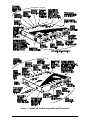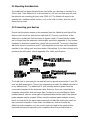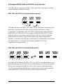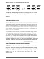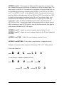
1
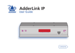
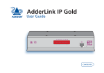
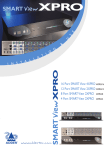
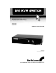
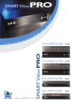
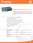
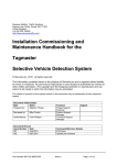
L-com
®
CONNECTIVITY
PRODUCTS
45 Beechwood Drive North Andover, MA 01845
V: 978.682.6936 F: 978.689.9484
[email protected] www.L-com.com
ISO 9002 Registered
Toll Free Ordering and Technical Support
800-341-5266
About this manual
AdderLink - Installation and Use
First edition (September 1999)
Part No. ADD0035/1
(c) 1999 Adder Technology Ltd.
All rights reserved. Whilst every precaution has been taken in the preparation of this
manual, Adder Technology Ltd assumes no responsibility for errors or omissions.
Neither is any liability assumed for damages resulting from the use of the
information contained herein. We reserve the right to change the specifications,
functions and circuitry of the product without notice.
Safety information
For use in dry, oil free indoor environments only.
Warning - live parts contained within power adapter.
No user serviceable parts within power adapter - do not dismantle.
Plug the power adapter into a socket outlet close to the AdderLink unit that it is
powering.
Replace the power adapter with a manufacturer approved type only.
Do not use the power adapter if the power adapter case becomes damaged,
cracked or broken or if you suspect that it is not operating properly.
If you use a power extension cord with the AdderLink, make sure the total
ampere rating of the devices plugged into the extension cord do not exceed the
cord’s ampere rating. Also, make sure that the total ampere rating of all the
devices plugged into the wall outlet does not exceed the wall outlet’s ampere
rating.
Do not attempt to service the AdderLink yourself.
AdderLink
Installation and Use
Page 1
Warranty
Adder Technology Ltd warrants that this product shall be free from defects in
workmanship and materials for a period of one year from the date of original
purchase. If the product should fail to operate correctly in normal use during the
warranty period, Adder will replace or repair it free of charge. No liability can be
accepted for damage due to misuse or circumstances outside Adder’s control. Also
Adder will not be responsible for any loss, damage or injury arising directly or
indirectly from the use of this product. Adder’s total liability under the terms of this
warranty shall in all circumstances be limited to the replacement value of this
product.
If any difficulty is experienced in the installation or use of this product that you are
unable to resolve, please contact your supplier.
Trademarks
All trademarks mentioned in this manual are acknowledged to be the property of the
respective trademark owners.
Adder is a registered trademark of Adder Technology Limited.
Compaq is a registered trademark of Compaq Computer Corporation.
Hewlett-Packard is a registered trademark of Hewlett-Packard.
IBM, PC/AT, PS/2, RS/6000 and ThinkPad are registered trademarks of
International Business Machines Corporation.
Logitech, MouseMan+ and Pilot Mouse+ are trademarks of Logitech Inc.
Microsoft and Windows are registered trademarks, and IntelliMouse is a trademark
of Microsoft Corporation.
Velcro is a trademark of Velcro USA Inc.
AdderLink
Installation and Use
Page 2
Radio Frequency Energy
A Category 5 (or better) twisted pair cable must be used to connect the AdderLink
units in order to maintain compliance with radio frequency energy emission
regulations and ensure a suitably high level of immunity to electromagnetic
disturbances.
All other interface cables used with this equipment must be shielded in order to
maintain compliance with radio frequency energy emission regulations and ensure a
suitably high level of immunity to electromagnetic disturbances.
European EMC directive 89/336/EEC
This equipment has been tested and found to
comply with the limits for a class A computing
device in accordance with the specifications in
the European standard EN55022. These limits
are designed to provide reasonable protection
against harmful interference. This equipment
generates, uses and can radiate radio frequency
energy and if not installed and used in
accordance with the instructions may cause
harmful interference to radio or television
reception. However, there is no guarantee that
harmful interference will not occur in a particular
installation. If this equipment does cause
interference to radio or television reception,
which can be determined by turning the
equipment on and off, the user is encouraged to
correct the interference with one or more of the
following measures: (a) Reorient or relocate the
receiving antenna. (b) Increase the separation
between the equipment and the receiver. (c)
Connect the equipment to an outlet on a circuit
different from that to which the receiver is
connected. (d) Consult the supplier or an
experienced radio / TV technician for help.
FCC Compliance Statement (United States)
This equipment generates, uses and can radiate
radio frequency energy and if not installed and
used properly, that is, in strict accordance with
the manufacturer’s instructions, may cause
interference to radio communication. It has been
tested and found to comply with the limits for a
class A computing device in accordance with the
specifications in Subpart J of part 15 of FCC
rules, which are designed to provide reasonable
protection against such interference when the
equipment is operated in a commercial
environment. Operation of this equipment in a
residential area may cause interference, in
which case the user at his own expense will be
required to take whatever measures may be
necessary to correct the interference. Changes
or modifications not expressly approved by the
manufacturer could void the user’s authority to
operate the equipment.
Canadian Department of Communications
RFI statement
This equipment does not exceed the class A
limits for radio noise emissions from digital
apparatus set out in the radio interference
regulations of the Canadian Department of
Communications.
Le présent appareil numérique n’émet pas de
bruits radioélectriques dépassant les limites
applicables aux appareils numériques de la
classe A prescrites dans le règlement sur le
brouillage radioélectriques publié par le
ministère des Communications du Canada.
AdderLink
Installation and Use
Page 3
Contents
1. Introduction..................................................................................... 6
1.1 AdderLink features ................................................................................. 6
1.2 Additional AdderLink Gold features ....................................................... 7
1.3 Product information ................................................................................ 8
1.4 Package contents................................................................................... 11
2. Installation....................................................................................... 13
2.1 What you will need ................................................................................ 13
2.2 Mounting the AdderLink ........................................................................ 15
2.3 Connecting your devices ....................................................................... 15
2.4 Configuring your PC(s) .......................................................................... 18
2.6 Configuring the AdderLink ..................................................................... 18
2.7 Setting the option switches ................................................................... 19
2.8 Setting the video compensation ............................................................ 22
2.9 Configuring the user-selectable options ................................................ 24
2.10 Summary of AdderLink configuration options ..................................... 25
2.11 Other useful installation information .................................................... 27
2.12 Hot plugging the AdderLink into running systems and re-enabling
disconnected PS/2 CPU mouse connections .............................................. 27
AdderLink
Installation and Use
Page 4
3. Using the AdderLink ..................................................................... 29
3.1 Power on status ..................................................................................... 29
3.2 AdderLink indicator lights ....................................................................... 30
3.3 Keyboard NUM,CAPS and SCROLL lock indicators .............................. 32
3.4 Keyboard hotkey control ........................................................................ 33
3.5 Entering an exiting video compensation / configuration mode .............. 35
3.6 Mouse control ........................................................................................ 35
3.7 Stereo audio support on the AdderLink Gold ......................................... 35
3.8 Microphone support on the AdderLink Gold .......................................... 36
3.9 Setting and using the security password ............................................... 36
3.10 Querying the AdderLink’s firmware version ........................................ 38
4. AdderLink configuration options.................................................. 39
4.1 RS232 protocol options ......................................................................... 39
4.2 Mouse mode and mouse switching of channels .................................... 40
4.3 Resetting all configuration options to their default state ........................ 41
Appendices
A - Cable and connector specifications ................................................................ 42
B - Problem solving .............................................................................................. 47
AdderLink
Installation and Use
Page 5
1. Introduction
Thank you for purchasing the AdderLink extender. Your AdderLink is designed to
transfer keyboard, video, mouse and RS232 signals up to 200 metres over Category
5 twisted pair cable. The AdderLink system consists of a transmitter (XL) and a
receiver (XR) unit that are connected together by a twisted pair cable. The XR unit
connects to your keyboard, monitor and mouse and the XL unit connects to the
computer system that is to be controlled.
The AdderLink extender is supplied in both standard (AdderLink) and enhanced
(AdderLink Gold) formats. In addition to the features supported by the AdderLink,
the AdderLink Gold system supports stereo audio and microphone signals and extra
connectivity options. This additional connectivity enables a second
keyboard/monitor/mouse set to be connected to the XL unit and an additional
computer system to be connected to the XR unit.
1.1 AdderLink features
Enables a keyboard, monitor, mouse and RS232 device to be located up to 200
metres from a computer.
Uses a single Category 5 (or better) unshielded twisted pair cable to carry all the
keyboard, video, mouse and RS232 signals.
Fine user-adjustable video compensation enables the video quality to be
maximised for any given length of cable.
The video compensation only needs to be adjusted once during setup. The
chosen compensation setting is retained in EEPROM memory even when the
AdderLink is powered off.
Mixed AT/PS2 keyboards and PS2/RS232 mice supported as standard.
Supports Microsoft IntelliMouse and other common wheel mice.
Password security prevents unauthorised use.
Supports high bandwidth monitors at resolutions up to 1600 x 1280.
Supports keyboard modes 1,2 and 3 and mouse prompt and stream modes for
maximum compatibility.
AdderLink
Installation and Use
Page 6
Power and activity indication confirm correct operation.
Standard cable connections make installation easy and inexpensive.
Robust metal case ensures good shielding and video quality.
19 inch rack mount kit available.
Supports IBM PC compatibles and RS6000 computers.
1.2 Additional AdderLink Gold features
Supports stereo audio and microphone signals.
Provides an additional user port (keyboard/monitor/mouse/speaker/microphone)
on the XL transmitter unit enabling the computer to be controlled from a location
close to the XL transmitter as well as a location close to the XR receiver.
Provides an additional computer port (keyboard/monitor/mouse/speaker/microphone) on the XR receiver unit enabling the user to control a local computer in
addition to the remote computer that is connected via the twisted pair cable.
Front panel indicators show the currently active user port and the currently
selected computer.
AdderLink
Installation and Use
Page 7
1.3 Product information
Figure 1 – AdderLink XL transmitter and XR receiver
AdderLink
Installation and Use
Page 8
Figure 2 – AdderLink Gold XL transmitter and XR receiver
AdderLink
Installation and Use
Page 9
Figure 3 – Mounting the AdderLink in the optional 19 inch rack mounting kit
AdderLink
Installation and Use
Page 10
1.4 Package contents
AdderLink package contents (part code: ALTX/ALRX)
Quantity
Description
1
1
1
1
AdderLink XL transmitter unit
AdderLink XR receiver unit
Instruction manual
Power adapter for the XR receiver unit
(Please note that the XL transmitter unit does not normally require a power adapter
because it draws its power from the computer via the keyboard interface cable. A
second power adapter is therefore NOT SUPPLIED but may be purchased
separately for video only applications.)
AdderLink Gold package contents (part code: ALGTX/ALGRX)
Quantity
Description
1
1
1
1
AdderLink Gold XL transmitter unit
AdderLink Gold XR receiver unit
Instruction manual
Power adapter for the XR receiver unit
(Please note that the XL transmitter unit does not normally require a power adapter
because it draws its power from the computer via the keyboard interface cable. A
second power adapter is therefore NOT SUPPLIED but may be purchased
separately for video only applications.)
AdderLink 19 inch rack-mount kit (part code: RMK-AL)
Quantity
Description
1
2
Mounting assembly for 19 inch racks
Counter-sunk screws for fixing AdderLink to mounting assembly
The rack-mount kit is suitable to mount the XL or XR unit into a 19 inch rack. If you
required to mount both the XR and the XL units in 19 inch racks then you will need
two rack-mount kits. The kit is suitable for the AdderLink and the AdderLink Gold.
AdderLink cable pack (part code: VSCP5)
AdderLink
Installation and Use
Page 11
This cable pack is suitable for connecting your computer to the AdderLink XL unit. It
is also suitable for connecting your computer to the AdderLink Gold XL unit or the
AdderLink Gold XR unit if you do not wish to use speakers or microphones. Your
PS/2 keyboard, PS/2 mouse and monitor may be plugged into the AdderLink
directly.
Quantity
Description
1
2
1
1
High resolution tri-coax video cable - 2 metres long
PS/2 keyboard/mouse cables - 2 metres long
Serial mouse adapter (plugs onto end of PS/2 cable)
AT keyboard adapter (plugs onto end of PS/2 cable)
AdderLink Gold cable pack (part code: VSCP5-GOLD)
This cable pack is suitable for connecting your computer to the AdderLink Gold XL
unit or the AdderLink Gold XR unit. Your PS/2 keyboard, PS/2 mouse, monitor,
stereo speakers and microphone may be plugged into the AdderLink Gold directly.
Quantity
Description
1
2
2
1
1
High resolution tri-coax video cable - 2 metres long
PS/2 keyboard/mouse cables - 2 metres long
Stereo speaker/microphone audio cables – 2 metres long
Serial mouse adapter (plugs onto end of PS/2 cable)
AT keyboard adapter (plugs onto end of PS/2 cable)
AdderLink
Installation and Use
Page 12
2. Installation
2.1 What you will need
A category 5 (or better) twisted pair cable of the required length to connect the
AdderLink XL and XR units together. These cables contain 4 pairs of twisted
wires. Specifications and recommended cable types are given in appendix A.
AdderLink supports cable lengths up to 200 metres. Structured wiring within
buildings may also be used together with suitable patch cables but the number of
cable connections should be kept to a minimum to maximise signal quality.
Cables to connect the AdderLink XL unit to your computer. Cable specifications
are given in appendix A. Cable packs are available for the AdderLink if you do not
wish to purchase individual cables. You do not need to connect cables for devices
that you do not wish to use with the exception of the keyboard cable which the
AdderLink XL unit uses to draw power from the computer. If you do not wish to
connect a keyboard then you may alternatively purchase an optional power
adapter (part code: PSU-IEC-5V DC)
A monitor with a standard VGA/SVGA (15 pin) connector that will work when
connected directly to your computer. If you are connecting an additional computer
to the AdderLink Gold XR unit then the monitor must also work when connected
directly to this computer. AdderLink supports low and high resolution monitors.
A standard AT or PS/2 style keyboard. If you are using an AT keyboard with a 5
pin connector you may connect this to the AdderLink using a standard AT to PS/2
keyboard adapter.
A PS/2 style two or three button Microsoft or Logitech compatible mouse or a
Microsoft IntelliMouse compatible mouse. If you have an AdderLink Gold and you
wish to use the mouse to switch the XR unit’s channel then you will need a three
button mouse or an IntelliMouse.
(The AdderLink supports ‘Internet Mice’ that are compatible with the Microsoft
IntelliMouse. These are fitted with a wheel or other scroll control and sometimes
have additional buttons. Examples are: Microsoft IntelliMouse, Logitech Pilot
Mouse+, Logitech MouseMan+, Genius NetMouse and Genius NetMouse Pro.)
AdderLink
Installation and Use
Page 13
A suitable mouse driver for your PC(s). Supported types are:
- PS/2 or RS232 two button mouse driver (any manufacturer).
- Microsoft mouse driver (including IntelliMouse).
- Logitech mouse driver (including two button, three button and wheel mouse)
If you have the AdderLink Gold then you may also require:
An additional set of computer cables to connect your additional computer to the
AdderLink Gold XR unit.
An additional keyboard, mouse and monitor of the type described above to
connect to the AdderLink XL unit.
One or two sets of stereo speakers.
One or two microphones.
If you require to connect serial devices you may also require:
Suitable conversion cables to connect your particular type of RS232 device.
Refer to appendix A for more details.
Use of PS/2 and RS232 style mice with the AdderLink - The mouse connections
from AdderLink to PCs support either a PS/2 or an RS232 mouse. AdderLink
automatically converts from the PS/2 mouse commands to RS232 serial mouse
commands. Serial mice types are selected by using an adapter as described in
Appendix A. The 9-pin D-type serial ports on the AdderLink may also be configured
to support serial mice but this setup is less ideal and is therefore not generally
recommended. The AdderLink will operate without a mouse connected if you do not
wish to use one.
AdderLink
Installation and Use
Page 14
2.2 Mounting the AdderLink
The AdderLink has been designed to be used either on a desktop or mounted in a
19 inch rack. If the AdderLink is to be mounted in a 19 inch rack then you will need
the optional rack mounting kit (part code: RMK-AL). The AdderLink may also be
mounted on a suitable vertical surface, such as the side of a desk, with the use of
strong Velcro strips.
2.3 Connecting your devices
Ensure that the power adapter is disconnected from the AdderLink and that all the
devices which are to be attached are switched off. Connect your devices to the
AdderLink or AdderLink Gold as shown in figures 4 and 5. Ensure that the cables
are no longer then the maximum cable lengths specified in appendix A. Any unused
computer or peripheral connections can be left unconnected. To connect computers
with serial mouse connections and AT style keyboard connections use the adapters
supplied in the cabling pack as shown below. Alternatively, if you have chosen not to
purchase the cable pack, refer to appendix A for cable specifications.
The AdderLink is now ready for use and will start to operate as soon the XL and XR
units are both powered on. There is no requirement to switch the AdderLink units on
in any defined order. The AdderLink XL unit normally draws its power from the
connected computer via the keyboard cable. However, if you are connecting to a
computer using cables that are longer than 3 metres or are connecting to a lower
powered device, such as some types of keyboard/video/mouse switch, the optional
power adapter may be required. When using the optional power adapter, ensure
that it is connected to the mains and powering the AdderLink before you switch on
the connected computers. Under these circumstances, failure to switch the
AdderLink and computers on in the correct order can lead to the mouse and/or
keyboard not being recognised by the computers when they are switched on.
AdderLink
Installation and Use
Page 15
Figure 4 – A typical AdderLink installation
AdderLink
Installation and Use
Page 16
Figure 5 – A typical AdderLink Gold installation
AdderLink
Installation and Use
Page 17
2.4 Configuring your PC(s)
Configure your PC in the same way that you would if your keyboard, mouse,
speakers, microphone and monitor were all connected directly to your PC, but
bearing in mind the following points:
AdderLink emulates Microsoft compatible serial, IntelliMouse and PS/2 mice, so
ensure that your PC software is configured for a Microsoft mouse of the correct
type. Refer to the list of supported drivers in section 2.1.
AdderLink supports VGA/SVGA/XGA/XGA2 type monitors, but does not support
the automatic detection features available with some ‘plug and play’ monitors
and video cards. If you have this type of video card and monitor, you should
select the video mode manually instead of relying upon the automatic detection
feature.
The sound quality of the AdderLink Gold’s audio speaker channels is maximised
by setting the maximum possible audio output level from your PC. You can then
adjust the speaker volume to suit.
The sound quality of the AdderLink Gold’s audio microphone channels is
maximised by setting the minimum possible audio input level to your PC.
2.5 Configuring the AdderLink
The AdderLink is supplied in a default state that is suitable for most applications
except that the video compensation needs to be adjusted to match the
characteristics of the twisted pair cable. The video only needs to be compensated
once during setup as the compensation value is stored by the AdderLink and
retained even when the power is off.
The AdderLink is configured using the following:
1. Option switches (see section 2.7)
The option switches on the side of the AdderLink select the keyboard hotkey
combination that is used to access video compensation / configuration mode. They
also control some other hardware related functions.
AdderLink
Installation and Use
Page 18
2. Video compensation / configuration mode (see section 2.8)
This mode is entered by typing the hotkey combination (selected using the option
switches) on the keyboard attached to the XR receiver. Once within video
compensation / configuration mode you can adjust the video compensation and
select other options using the keyboard. The selected options are saved and stored
in the XR unit when you exit compensation / configuration mode.
2.6 Setting the option switches
The option switches on the side of the AdderLink XR and XL units are used to select
operating options. The switches are continuously read by the AdderLink and may be
changed whilst the AdderLink is powered on. The default setting (all switches OFF)
is suitable for most installations. The switches are shown in figures 6 and 7 and
have the following functions.
XR unit - Switches 1 to 5
Reserved – set to OFF position
XR unit - Switches 6 to 8
These switches select the hotkey combinations that are recognised by the
AdderLink. The chosen hotkey combinations are used to enter compensation /
configuration mode, lock the AdderLink, disable the AdderLink’s video and select
between local and remote computers on the AdderLink Gold.
XL unit – Switch 1
This switch may be used to reset the XL unit without disconnecting the power. In the
OFF position the AdderLink will operate normally. In the ON position the AdderLink
will suspend all operation and reset itself to the power off condition. Cycling the
switch from the OFF position to the ON position and back to the OFF position again
will perform a reset without having to disconnect the keyboard lead and power lead.
XL unit - Switches 2,3,4 and 6
Reserved – set to OFF position
XL unit – Switch 5
If this switch is set to the ON position then the remote unit will go directly into
compensation / configuration mode at power on. This enables a password locked
XR unit to be reset. See section 3.9 for further details.
AdderLink
Installation and Use
Page 19
XL unit - Switches 7 and 8
These switches have no function on the AdderLink. On the AdderLink Gold, the
switches select the timeout period for switchover of computer control between the
local (XL) and remote (XR) units. The timeout period is the duration of keyboard and
mouse inactivity that must be detected before the AdderLink Gold will switch control
between the local (XL) and remote (XR) user console. The AdderLink Gold allocates
control of the computer to the first keyboard / mouse set (local XL or remote XR)
that sends keyboard or mouse data. The other keyboard / mouse set is then
prevented from accessing the computer until no keyboard or mouse data has been
received for the timeout period. Once a timeout has occurred either keyboard /
mouse set may access the computer on a first come first served basis.
Figure 6 – AdderLink XR option switches (normal and Gold models)
AdderLink
Installation and Use
Page 20
Figure 7 – AdderLink XL option switches (normal and Gold models)
AdderLink
Installation and Use
Page 21
2.8 Setting the video compensation
The AdderLink incorporates fine video compensation amplifiers to maximise the
picture quality for any given length of twisted pair cable. When you first plug in your
AdderLink you will probably notice that the picture appears blurred or distorted or
does not appear at all. The picture quality is maximised by adjusting the video
compensation setting. To do this use the following procedure.
STEP 1
f
Enter video compensation mode by pressing the HOTKEYS together with
on
the keyboard connected to the XR receiver unit. The HOTKEYS are those that were
set using the option switches (CTRL + ALT by default).
For example, assuming the default hotkeys, press these keys together :
b a f
STEP 2
The AdderLink will now be in compensation adjustment mode. This is indicated by
the NUM, CAPS and SCROLL lock lights on your keyboard. These will flash in
sequence at a rate that indicates the level of compensation: a slow rate of flash
indicates a compensation setting suitable for short lengths of twisted pair cable and
a fast rate of flash indicates a compensation setting that is suitable for long lengths
of twisted pair cable.
Press
AdderLink
g
to select no video compensation.
Installation and Use
Page 22
You should now see a ‘fuzzy’ video picture on your monitor connected to the XR
receiver unit.
STEP 3
You may now use the following keys to select the required video compensation.
g
{
w
}
y
Selects no video compensation.
Increases the video compensation (coarse adjustment).
Increases the video compensation (fine adjustment).
Decreases the video compensation (coarse adjustment).
Decreases the video compensation (fine adjustment).
Various other keys may also be used to select operating options (see section 2.10)
As you change the video compensation setting you will see the sharpness of the
picture change. The AdderLink calculates the required brightness automatically. You
will need more video compensation for longer twisted pair cable distances. Adjust
the video compensation until you achieve the best picture. If you add too much
compensation then the picture may be lost. If this happens reduce the compensation
to restore the picture.
AdderLink
Installation and Use
Page 23
The best compensation setting may be set using the following technique.
{
•
Press
until you observe white trailing edges on the right hand side of
black text or graphics.
•
Press and release
yseveral times until the white trailing edges just disappear.
STEP 4
Press
f
to exit from compensation mode.
The AdderLink saves the selected video compensation setting when you exit from
compensation mode. This setting is retained within the AdderLink even when the
power is off and so unless you change the twisted pair cable you will not need to readjust the compensation setting again.
2.9 Configuring user-selectable options
The AdderLink supports a number of user-configurable options that change the
detailed operation of the AdderLink to match the required application. These may be
selected whilst the AdderLink is in video compensation / configuration mode. Whilst
within configuration mode the version number of the AdderLink’s firmware may also
be queried.
f
To enter configuration mode press the HOTKEYS together with
on the
keyboard connected to the XR receiver unit. The HOTKEYS are those that were set
using the option switches (CTRL + ALT by default).
For example, assuming the default hotkeys, press these keys together :
b a f
AdderLink
Installation and Use
Page 24
Options are then set by pressing a letter key followed by a number key followed by
the RETURN key. For example to select an RS232 baud rate of 1200 use the
following:
Whilst within configuration mode press
B1f
The num, caps and scroll lock lights will indicate correct acceptance of the command
as follows:
•
•
•
•
In compensation / configuration the num, caps and scroll lock lights will flash in
sequence.
After pressing the first key of a command sequence the num, caps and scroll
lock lights will all be illuminated.
After pressing the second key of a command sequence the num and caps lock
lights will be on and the scroll lock light will be off.
After pressing RETURN the command will have been accepted and the num,
caps and scroll lock lights will go back to flashing in sequence.
When you have finished selecting options, return to normal operation by pressing
f
2.10 Summary of AdderLink configuration options
Full details of each of the configuration options and their uses are given in section 4.
B1 f
- Set RS232 baud rate to 1200 (default) (see section 4.1)
B2 f
- Set RS232 baud rate to 9600
F1 f
- Query AdderLink firmware version (see section 3.10)
F8 f
- Resets all user-configurable options to the default state (see 4.3)
AdderLink
Installation and Use
Page 25
H1 f
- Mouse compatible RS232 protocol (default) – overrides all other
RS232 settings (see section 4.1)
H2 f
- RS232 protocol uses hardware handshaking
H3 f
- RS232 protocol uses no handshaking (1200 baud max.)
M1 f
- AdderLink Gold channels are not switchable by a 3-button mouse
or IntelliMouse (default) (see section 4.2)
M2 f
- AdderLink Gold channels are switchable by a 3-button mouse or
IntelliMouse (see section 4.2)
M6 f
- Reset mouse function (see section 2.12)
M7 f
- Reset IntelliMouse function (see section 2.12)
Pf {PASSWORD} f – Sets a security password (see section 3.9)
Pf f – Clears the security password (see section 3.9)
S1 f
- RS232 protocol uses 1 stop bit (see section 4.1)
S2 f
- RS232 protocol uses 2 stop bits (default)
S3 f
- RS232 protocol uses no parity (default) (see section 4.1)
S4 f
- RS232 protocol uses even parity
S5 f
- RS232 protocol uses odd parity
S7 f
- RS232 protocol uses 7 bits per character (default) (see 4.1)
S8 f
- RS232 protocol uses 8 bits per character
AdderLink
Installation and Use
Page 26
2.11 Other useful installation information
PC boot up sequence - When your PCs are powered on they communicate with
any attached keyboards and mice and setup parameters required by the particular
operating system. It is necessary for the AdderLink to be attached and powered on
during this sequence so that it can give the required responses and keep track of all
the modes and settings requested by each of the connected PCs.
Mouse characteristics - do not unplug a PS/2 mouse connection from a PC whilst
the PC is on. Due to the design of PS/2 mice communications the mouse function on
the PC will be lost and you will have to re-boot the PC to regain normal operation.
Unplugging the mouse from the AdderLink will also cause it to stop operating when it
is plugged back in. RS232 mice can usually be unplugged and plugged back in
provided that a mouse was connected when the operating system initially booted.
Keyboard and mouse mode switching - The AdderLink keeps a log of the
keyboard and mouse mode and resolution settings requested by the connected
PC(s). These settings are automatically communicated to the keyboard and mouse
as required to ensure maximum software compatibility. The keyboard num, caps
and scroll lock states are an obvious example of this process.
2.12 Hot plugging the AdderLink into running systems and reenabling disconnected CPU PS/2 mouse connections
It is adviseable to switch off the systems that are going to be connected to the
AdderLink before installation. However if this is not possible then most systems can
be hot plugged by using the AdderLink’s mouse restoration functions. The keyboard
connection will normally restore itself automatically.
On many PCs, mouse movement will be lost if the PS/2 mouse is unplugged and
plugged back in whilst the PC is running. Mouse movement can then only be
restored by rebooting the PC. This is because the mouse drivers only setup and
enable the mouse when the PC is initially booted.
If you have switched off your AdderLink or you are attempting to ‘hot plug’ it into a
system that is already running, you may be able to restore lost mouse movement
using the AdderLink's mouse restoration functions.
AdderLink
Installation and Use
Page 27
Mouse restoration functions should be used with care as unpredictable
results may occur if the wrong mouse type is selected. If in doubt restore the
mouse by powering down the PC normally.
Standard PS/2 mouse data uses a different data format to IntelliMouse data and so
two reset functions are provided on the AdderLink. The type of data format expected
by the PC depends upon the driver and the type of mouse that was connected when
the driver was booted. The following table may be used as a guide.
Note that the mouse reset functions predict the likely mouse resolution settings but
may not restore the speed or sensitivity of the mouse exactly as they were when the
PC originally booted.
Type of mouse / system
Connected at bootup
PS/2
PS/2
IntelliMouse / ADDERview
IntelliMouse / ADDERview
Driver type
PS/2 only
IntelliMouse
PS/2 only
IntelliMouse
Likely expected
data format
PS/2
PS/2
PS/2
IntelliMouse
Suggested
restoration
F5
F5
F5
F6
To restore lost mouse movement on a CPU connected to the AdderLink:
1) Ensure that the video picture of the CPU that has lost its mouse movement is
displayed on the monitor connected to the XR unit.
2) Enter the configuration mode by pressing ‘HOTKEYS’ and RETURN on the
keyboard connected to the XR unit. For example:
b af
3) To restore a PS/2 mouse connection press
M 6 f
Or, to restore an IntelliMouse connection press
M 7 f
4) Exit from configure mode by typing
f
5) Test the mouse movement by moving the mouse a short distance.
AdderLink
Installation and Use
Page 28
3. Using the AdderLink
This section explains the general operation of the AdderLink. We recommend that
you read this section before starting to use the product.
3.1 Power on status
The AdderLink is ready for use as soon as the XR receiver and XL transmitter have
been powered on. Remember that the XL transmitter usually draws its power from
the computer via the keyboard cable and the XR unit draws its power form the
supplied power adapter.
If a security password has not been set then the AdderLink XR unit will power on
and immediately establish a link to the remote computer attached to the XL unit. On
the AdderLink this is indicated by the activity light illuminating and on the AdderLink
Gold this is indicated by the remote (1) light illuminating.
If a security password has been set then the AdderLink XR unit will only illuminate
the power light on the XR unit and will not display any video. The AdderLink will
indicate that it is waiting for a password to be entered by alternately illuminating the
num and scroll lock lights and then the caps lock light on the keyboard attached to
the XR receiver unit.
The AdderLink XL unit draws its power from the attached CPU via the keyboard
cable. The green power light confirms that there is sufficient power available. If the
power light flashes or is off continuously then there is not sufficient power available.
AdderLink
Installation and Use
Page 29
3.2 AdderLink indicator lights
The AdderLink indicator lights have the following meaning
AdderLink XL
Indicator
Colour
Status
POWER
Green
ON
ACTIVITY
Red
ON
AdderLink is on and there is sufficient
power available
OFF
AdderLink is off and sufficient power is not
available
FLASHING Insufficient power is available (marginal
power)
OFF
LINK
Orange
Meaning
Keyboard or mouse data is being received
from the XR unit
No keyboard or mouse data is being
Received from the XR unit
ON
OFF
The XL unit is connected to an XR unit
The XL unit is not connected to an XR unit
AdderLink XR
Indicator
Colour
Status
Meaning
POWER
Green
ON
OFF
AdderLink is on
AdderLink is off
ACTIVITY
Red
ON
The AdderLink is not locked and no
keyboard or mouse data is being received
FLASHING The AdderLink is not locked and keyboard or
Mouse data is being received
OFF
The AdderLink is locked or disabled
LINK
Orange
ON
OFF
AdderLink
The XR unit is connected to an XL unit
The XR unit is not connected to an XL unit
Installation and Use
Page 30
AdderLink Gold XL
Indicator
Colour
Status
POWER
Green
ON
REMOTE A Red
AdderLink is on and there is sufficient
power available
OFF
AdderLink is off and sufficient power is not
available
FLASHING Insufficient power is available (marginal
power)
ON
OFF
LOCAL B
Red
Meaning
ON
OFF
Keyboard or mouse data has been received
from the XR unit and the keyboard and mouse
attached to the XR unit have control of the PC
The keyboard and mouse attached to the XR
unit do not have control of the PC
Keyboard or mouse data has been received
from the keyboard and mouse attached to the XL
unit which currently have control of the PC
The keyboard and mouse attached to the XL
unit do not have control of the PC
AdderLink Gold XR
Indicator
Colour
Status
Meaning
POWER
Green
ON
OFF
AdderLink is on
AdderLink is off
REMOTE 1 Red
ON
Remote PC attached to XL unit is selected
OFF
Remote PC attached to XL unit is not selected
FLASHING Remote PC is selected and keyboard / mouse
data if being received
LOCAL 2
ON
Local PC attached to XR unit is selected
OFF
Local PC attached to XR unit is not selected
FLASHING Local PC is selected and keyboard / mouse
data if being received
AdderLink
Red
Installation and Use
Page 31
3.3 Keyboard NUM, CAPS and SCROLL lock indicators
The AdderLink uses the keyboard NUM, CAPS and SCROLL lock lights to indicate
various operating conditions as follows:
NUM, CAPS and SCROLL lock lights flash in sequence
The AdderLink flashes the NUM, CAPS and SCROLL lock lights in sequence on the
keyboard connected to the XR unit to indicate that the AdderLink is in video
compensation / configuration mode. The NUM lock light comes on first with CAPS
and SCROLL off. Then the CAPS lock comes on with NUM and SCROLL off and
finally the SCROLL lock comes on with NUM and CAPS off. The rate of flashing
indicates the level of video compensation applied by the video compensation
amplifiers. A slow flash rate indicates a small amount of compensation (short twisted
pair cable distance). A fast flash rate indicates a greater level of video
compensation for longer cables.
NUM, CAPS and SCROLL lock lights flash together
The AdderLink Gold flashes the NUM, CAPS and SCROLL lock light together on the
keyboard attached to the XL unit or the keyboard attached to the XR unit to indicate
that the other keyboard currently has control of the computer connected to the XL
unit. These lights will stop flashing when a timeout has occurred and the computer
connected to the XL unit is free for use by either keyboard/mouse set.
AdderLink
Installation and Use
Page 32
NUM and SCROLL lock flash alternately with CAPS lock
The AdderLink alternately flashes NUM and SCROLL lock and then CAPS lock on
the keyboard attached to the XR unit to indicate that the AdderLink is currently
locked and is awaiting a password to be entered by the user to unlock the
AdderLink.
3.4 Keyboard hotkey control
AdderLink XR unit may be set to respond to various keyboard hotkey combinations.
These keyboard hotkeys are selected using the option switches on the side of the
AdderLink XR unit (see section 2.7). Keyboard hotkeys may be used to switch off
the video, lock the AdderLink and enter video compensation / configuration mode.
On the AdderLink Gold the keyboard hotkeys are also used to select between the
remote (1) and local (2) computers.
All of the hotkey control commands are invoked by holding down the two hotkeys
and then pressing a command key. By default, the two hotkeys are ‘CTRL’ and
‘ALT’, although other combinations can be selected by reconfiguring the hotkeys
(see section 2.7). Once the hotkey command has been activated you will need to
release the hotkeys and the command key before a new hotkey command is
accepted by the AdderLink. HOTKEYs + TAB is an exception and this allows you to
'tab through' the ports by holding down the hotkeys and repeatedly pressing TAB.
The hotkey commands are summarised below (IMPORTANT NOTE: the numbers
on the numeric keypad do not form part of a valid hotkey) :
‘HOTKEYs’ and ‘0’ – switches off the video signal and all the associated red status
lights on the XR unit and disconnects the keyboard and mouse from the computer
that they are currently controlling. This will cause some monitors to go into standby
mode or switch off. The video signal can be re-enabled by selecting a computer
using ‘HOTKEYs’ and ‘TAB’ or ‘HOTKEYs’ and ‘1’ (or ‘HOTKEYs’ and ‘2’ on the
AdderLink Gold) .
AdderLink
Installation and Use
Page 33
‘HOTKEYs’ and ‘L’ - Disconnects the AdderLink XR’s keyboard and mouse from
the computer that they are controlling and switches off all the red status lights. The
video signal is switched off. If a password has not been set then the AdderLink can
be re-enabled by selecting a computer using ‘HOTKEYs’ and ‘TAB’ or ‘HOTKEYs’
and ‘1’ (or ‘HOTKEYs’ and ‘2’ on the AdderLink Gold). If a password has been set
then the AdderLink will alternately flash the NUM and SCROLL and then the CAPS
lock lights on the keyboard connected to the XR unit. This indicates that a valid
password must be entered to unlock the AdderLink. Simply type the same key
combination as was set during configuration (see section 3.9) followed by the
RETURN key. Note - if anyone has typed at the keyboard whilst in secure mode, it
will be necessary to type RETURN first to clear the invalid password, then type the
valid password followed by RETURN again.
‘HOTKEYs’ and ‘1’ - selects the remote computer attached to the XL unit
‘HOTKEYs’ and ‘2’ - selects the local computer attached to the XR unit (AdderLink
Gold only)
‘HOTKEYs’ and ‘TAB’ – Selects the next computer (remote or local)
‘HOTKEYs’ and RETURN – Enters video compensation / configuration mode
Examples of common hotkey sequences (assuming CTRL + ALT hotkey option):
To lock the AdderLink
press
baL
release
Lba
To 'tab through' computers (AdderLink Gold):
press
ba v release v press v
release
AdderLink
v press v release vba
Installation and Use
Page 34
3.5 Entering and exiting video compensation / configuration mode
The AdderLink’s video compensation and user selectable options and functions are
accessed in compensation / configuration mode. To enter this mode press the
selected hotkey combination together with the RETURN key and to exit this mode
press the RETURN key again. For example:
To enter compensation / configuration mode:
press
baf
release
fba
release
f
To exit compensation / configuration mode:
press
f
3.6 Mouse control
On the AdderLink Gold XR unit, the computers can conveniently be selected using a
three button mouse or IntelliMouse. In order to switch to the other computer simply
hold down the central mouse button or wheel button and click on the left hand
mouse button. The other computer will then be selected. In order to use this feature
you must enable it using the M2 option in configuration mode (see section 4.2).
3.7 Stereo audio support on the AdderLink Gold
You may connect stereo speakers to both the AdderLink Gold XL unit and the
AdderLink Gold XR unit. Audio from the computer connected to the XL unit is
broadcasted to the speakers attached to the XL unit and to the XR unit. The
speakers on the XR unit will output the audio signal from the XL unit if the remote
computer (1) is selected or the audio from the computer connected to the XR unit if
the local computer (2) is selected.
The AdderLink transfers the audio speaker signals between the XL and XR units by
multiplexing the audio signals onto the video signals. A small degree of audio noise
is introduced by this process. The effect of this noise may be reduced by the
following actions:
AdderLink
Installation and Use
Page 35
•
•
•
Set the speaker output volume on the PC connected to the XL unit to the highest
setting available.
Adjust speaker volume control knob away from the maximum setting.
Do not boost the audio BASS signal if this can be avoided.
The AdderLink is designed to carry audio signals with a maximum peak-to-peak
voltage of 5 volts. This is suitable for most PC audio outputs. If you are sending
audio with a higher peak-to-peak value than 5 volts this may affect the video picture
causing temporary loss of the picture during peak audio output. If you are
transferring such an audio signal then reduce the PC’s maximum output volume
setting until the picture remains fully stable.
3.8 Microphone support on the AdderLink Gold
You may connect a microphone to both the AdderLink Gold XL unit and the
AdderLink Gold XR unit. The computer attached to the XL unit will take its
microphone input from the last active user port. So, if the keyboard and mouse on
the XR unit were last used to control the computer then the microphone signal will
be taken from the XR unit. Alternatively if the keyboard and mouse connected to the
XL unit were the last to control the computer then the microphone signal will come
from the microphone attached to the XL unit.
If the local computer (2) is selected on the XR unit then, as expected, its microphone
signal will be taken from the microphone attached to the XR unit.
The AdderLink transfers the audio microphone signals between the XR and XL units
by multiplexing the audio signals onto the video signals. A degree of audio noise is
introduced by this process. The effect of this noise may be reduced by setting the
microphone audio input volume on the PC connected to the XL unit to the lowest
practical setting.
3.9 Setting and using the security password
There are many situations where unrestricted access to computers or sensitive
information needs to be controlled. In such circumstances, the AdderLink XL unit
may be locked away in a room or secure cabinet and the computer may be
controlled remotely from the XR unit.
AdderLink
Installation and Use
Page 36
The AdderLink incorporates a security password system that enables the XR unit to
be locked so that the secure computer cannot be controlled. Once a password has
been set the AdderLink XR unit may be disabled by pressing the hotkeys together
with the L (lock) key. The XR unit may only then be unlocked by entering the
password. For example if the hotkeys are set to CTRL and ALT then pressing the
following key combination would cause the AdderLink XR unit to lock.
baL
When the XR unit is locked the video is switched off and the keyboard and mouse
are disconnected from the computer. Locking the XR unit does not affect the
operation of the XL unit.
To unlock the AdderLink XR unit enter the password followed by the RETURN key
eg:
PASSWORDf
NOTE - The password consists of a combination of key strokes rather like the code
to a safe. The key strokes are not case sensitive and can include all the keys on the
keyboard (except ctrl, alt, shift and enter). Consequently the following 'password'
would be valid:
oFRED g
To set the password, enter configuration mode by typing ‘HOTKEYS’ and RETURN
on the keyboard attached to the XR unit (see section 3.5). When in configure mode
type ‘P’ then RETURN. Now enter the password which may be up to 40 characters.
The password is not case sensitive and can be any combination of key strokes,
including the function keys, but excluding the CTRL, ALT, SHIFT and RETURN
keys. When you have typed in your password type RETURN to register it in the
stored memory. Do not worry if you type the password incorrectly, you can always
re-enter configure mode and set the password again.
AdderLink
Installation and Use
Page 37
For example, to enter OPENUP as the password type the following whilst in
configuration mode:
PfOPENUPf
What to do if your AdderLink is locked and you have lost or forgotten the
password
If your AdderLink is locked and you have lost or forgotten the password then you
may clear the password if you have access to the XL unit. To clear the password
power down the XR unit and switch option switch 5 on the XL unit to the on position
(see section 2.7). When you next power on the XR unit it will go straight into
configuration mode allowing you to clear or change the password. You will then
need to set option switch 5 on the XL unit back to its default (off) position or the XR
unit will go into configuration mode every time that you switch it on.
3.10 Querying the AdderLink’s firmware version
For technical support purposes it is sometimes useful to know the firmware version
of the AdderLink. The AdderLink can report its firmware version using a
configuration mode function.
To find the firmware version of your AdderLink, connect to a computer that is
showing the DOS prompt or is running a text editor or word processor package. On
the AdderLink this will be the computer connected to the XL unit. On the AdderLink
Gold this may be the computer connected to the XL unit or the computer connected
to the XR unit.
It doesn’t matter what package this is provided that the characters typed in at the
keyboard are displayed on the screen. Enter configuration mode by pressing
‘HOTKEYs’ and RETURN together (see section 3.5). Now type the following on the
keyboard connected to the XR unit:
F1 f
The version number will be reported on the computer screen as the letter V followed
by three numbers. For example, if the AdderLink reports V118 then the firmware
version is 1.18.
AdderLink
Installation and Use
Page 38
4. AdderLink configuration options
All the options described in this section are entered in AdderLink’s configuration
mode - see section 3.5 for instructions on entering configuration mode.
4.1 RS232 protocol options
RS232 serial ports are used for a wide variety of purposes and are typically
operated in a number of different modes. A mode that is suitable for one type of
device may not be suitable for other devices and so the RS232 protocol supported
by the AdderLink may be changed to suit different applications.
Refer to appendix A for suitable cabling for various RS232 applications. Appendix A
also shows the signal pinouts for the RS232 ports.
If you are using an RS232 serial mouse connection to any of the CPUs that are
connected to the AdderLink then you will need to set the AdderLink into RS232
mouse compatible mode. Setting this mode overrides all other RS232 protocol
settings and forces 1200 baud, 8 bits per character, 1 stop bit and no handshaking.
The AdderLink performs an automatic conversion to convert PS/2 mouse signals to
RS232 mouse signals if you use a suitable wiring adapter. If you wish to use an
RS232 mouse connection to your PC then we recommend that you use a controlling
PS/2 mouse and the RS232 adapter rather than attempting to connect the mouse to
the serial ports on the AdderLink. The reason for this is that in the recommended
setup the XL unit will continuously emulate the presence of a serial mouse
regardless of whether the XR unit is connected and currently powered on . This
ensures that PC will reliably bootup regardless of the power and connection state of
the AdderLink.
The various RS232 protocol modes may be set using the following options within
configuration mode:
H1 f
- Mouse compatible RS232 protocol (default) – overrides all other
RS232 settings
H2 f
- RS232 protocol uses hardware handshaking
H3 f
- RS232 protocol uses no handshaking (1200 baud max.)
AdderLink
Installation and Use
Page 39
B1 f
- Set RS232 baud rate to 1200 (default)
B2 f
- Set RS232 baud rate to 9600
S1 f
- RS232 protocol uses 1 stop bit
S2 f
- RS232 protocol uses 2 stop bits (default)
S3 f
- RS232 protocol uses no parity (default)
S4 f
- RS232 protocol uses even parity
S5 f
- RS232 protocol uses odd parity
S7 f
- RS232 protocol uses 7 bits per character (default)
S8 f
- RS232 protocol uses 8 bits per character
4.2 Mouse mode and mouse switching of channels
Mouse switching is only relevant on the AdderLink Gold product where the user
connected to the XR unit requires to switch between the remote computer (1)
connected to the XL unit and the local computer (2) connected to the XR unit. This
may be done by a keyboard hotkey combination or by using a three button PS/2
mouse or an IntelliMouse.
To switch between the remote (1) and local (2) computers, the user simply holds
down the central button or wheel button and presses the left hand button to change
channel. To use this feature it must first be enabled using the M2 option. To disable
this feature use the M1 option.
If the third button is being used to switch the AdderLink XR then it is not available for
use with PC software although the function of an IntelliMouse wheel is not affected.
Consequently in M2 mode the AdderLink reports to the PCs that a 2 button mouse is
connected. If you wish to use the full function of a 3 button mouse or IntelliMouse for
your PC software then you should select the M1 option.
AdderLink
Installation and Use
Page 40
The AdderLink supports ‘Internet Mice’ that are compatible with the Microsoft
IntelliMouse. These are fitted with a wheel or other scroll control and sometimes
have additional buttons. Examples are:
Microsoft IntelliMouse
Logitech Pilot Mouse +
Logitech MouseMan+
Genius NetMouse
Genius NetMouse Pro
Standard PS/2 and IntelliMouse compatible mice may be connected to the
AdderLink. You may configure your CPUs using Microsoft PS/2 or IntelliMouse
drivers in any combination as required. The IntelliMouse features are supported on
both PS/2 and RS232 CPU connections. When using PS/2 CPU connections, the
AdderLink will automatically configure itself to the type of mouse requested by the
driver.
M1 f
- AdderLink Gold XR channels are not switchable by a 3-button
Mouse or IntelliMouse (default)
M2 f
- AdderLink Gold XR channels are switchable by a 3-button mouse
or IntelliMouse
4.3 Resetting all configuration options to their default state
To reset all the AdderLink’s configuration options to the default state and return all
the AdderLink settings to their default state press the following whilst within
configuration mode. By resetting all the configuration options to their default state
you will also clear the password but you will not change the video compensation
setting.
F8 f
AdderLink
Installation and Use
Page 41
Appendix A. Cable and connector
specifications
IMPORTANT NOTE
The maximum cable lengths supported vary widely between devices and
cables. It may be possible to use cables that are longer than those specified
below with certain PCs and peripherals but this cannot be guaranteed. If you
experience problems try using shorter cables.
A1. Keyboard, monitor, mouse, microphone and speakers
connections
All of these devices plug directly into the relevant ports of the AdderLink. If you use
an AT style keyboard you will need an AT (5 pin DIN female) to PS/2 (6 pin mini-DIN
male) converter.
Cable specification for connections to XL unit when used without the optional
power adapter
Keyboard, monitor, mouse, speaker and microphone cables should not be longer
than 2 metres.
Cable specification for connections to XR unit or to XL unit when used with
the optional power adapter
Keyboard, monitor, mouse, speaker and microphone extension cables can be used
to increase the distance from the AdderLink up to 10metres. Most keyboards and
mice will also operate at distances of 20 metres. If you are using a monitor extension
cable then you should ensure that this is a high quality tri-coax type.
A2. Computer connections
Cable specifications:
Video - 15 pin high density male D connector to 15 pin high density male D
connector wired as a standard VGA PC to monitor cable. There are two types
commonly available. The best type cables which will give excellent quality are
AdderLink
Installation and Use
Page 42
constructed with coaxial cable cores. Cheaper ‘data’ cables are available but
generally give rather poor quality. Avoid using 'data' cables longer than 2 metres
unless the video quality is not important. Good quality coaxial video cables may be
run at distances up to 20 metres with little loss of video quality.
Keyboard and PS/2 mice - 6 pin mini-DIN male connector to 6 pin mini-DIN male
connector with all lines connected straight through (1-1,2-2 etc.). If the PC has a 5pin DIN AT style keyboard connector you will need a PS/2 to AT keyboard adapter
6-pin mini-DIN female to 5-pin DIN male (readily available). For ‘self powered’
operation of the XL unit without the optional power adapter the cables should be no
longer than 3 metres. For operation with the power adapter, cables should be no
longer than 20 metres.
RS232 serial mice - these require a special converter to connect the RS232 lines
present on the AdderLink mouse ports to the RS232 port on a PC.
Cables should be no longer than 20 metres.
Speaker and microphone cables – Screened audio cables with a stereo audio jack
on both ends should be used. Where possible keep the cable lengths to a minimum.
The maximum recommended length is 5 metres.
AdderLink
Installation and Use
Page 43
A3. Twisted pair cable
Many types of twisted pair cables are available. You may use unshielded twisted
pair (UTP) or shielded twisted pair (STP) cable with the AdderLink. Ensure that the
cable you use is of Category 5 or better specification.
The AdderLink uses the following pairs on the twisted pair RJ45 jack connector. If
your cable is terminated for networking use then it will probably be wired correctly for
the AdderLink. All four twisted pairs within the cable are used by the AdderLink.
BICC Brand - Rex cables are particularly recommended for use with the AdderLink
The usage of the various twisted pairs is shown below:
AdderLink
Installation and Use
Page 44
Maximising the video quality for long cable lengths
All twisted pair cables are constructed so that each of the twisted pairs has a slightly
different twist rate. This is to reduce the electrical cross-talk between signals
travelling on adjacent pairs. This difference in twist frequency effectively means that
the wire distance that an electrical signal has to traverse is different for the different
pairs. This does not normally cause a noticeable problem but for higher screen
resolutions at longer cable lengths a colour separation effect may start to be
observed.
In practice most networking cables have one pair of conductors that are significantly
more tightly twisted than the other three. Unfortunately this varies between cable
types and manufacturers. If you do observe a colour separation effect at high screen
resolutions and longer cable lengths then this may be improved by swapping the
twisted pairs that are used within the cable. To gain the best results the red, green
and blue AdderLink colour signals should be sent over the three pairs that have the
closest twist frequency. This normally means that the pair with the tightest twist
frequency should be avoided.
If you do not already have a cable and you wish to purchase a suitable cable then
this may be purchased from Adder Technology via your supplier. High quality cables
are also available that remove this colour separation effect completely.
A4. RS232 port pin assignments
View of AdderLink 9-way D-type female socket
AdderLink
Installation and Use
Page 45
RS232 cables for mouse applications
Computer to AdderLink RS232 cable for RS232 mouse applications
Computer-end 9-pin female connector
AdderLink-end 9-pin male connector
2
2
3
3
5
5
7
4
Mouse to AdderLink cable / adapter
Mouse-end 9-pin male connector
AdderLink-end 9-pin male connector
2
3
3
2
4
6
5
5
7
8
6
4
8
7
RS232 cables for printer applications
Computer to AdderLink RS232 cable for RS232 printer applications
Computer-end 9-pin female connector
AdderLink-end 9-pin male connector
All lines connected straight through 1-1,2-2,3-3 etc.
AdderLink to printer with 25-way connector
AdderLink-end 9-pin male connector
Printer-end 25-pin male connector
2
3
3
2
4
20
5
7
6
6
8
5
AdderLink
Installation and Use
Page 46
Appendix B.
Problem Solving
Problem:
Video picture is lost during very high audio output.
Action:
Reduce the maximum audio output level
AdderLink
Installation and Use
Page 47
Notes
AdderLink
Installation and Use
Page 48
Notes
AdderLink
Installation and Use
Page 49