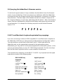
1
USB
U
S
E
ADDERView
&
I
www.addertec.com
N
ADDERView USB
L A
L
T A
S
N
I
T
O
4 Port ADDER View USB AV4USB-PC
4 Port ADDER View USB AV4USB-MAC
Remote Control Pad/Display RC1
About this manual
AdderView USB - Installation and Use
First edition (November 1999)
Part No. ADD0036/1
(c) 1999 Adder Technology Ltd.
www.addertec.com
All rights reserved. Whilst every precaution has been taken in the preparation of this
manual, Adder Technology Ltd assumes no responsibility for errors or omissions.
Neither is any liability assumed for damages resulting from the use of the information
contained herein. We reserve the right to change the specifications, functions and
circuitry of the product without notice. All trademarks acknowledged.
Safety information
For use in dry, oil free indoor environments only.
Warning - live parts contained within power adapter.
No user serviceable parts within power adapter - do not dismantle.
Plug the power adapter into a socket outlet close to the AdderView unit that it is
powering.
Replace the power adapter with a manufacturer approved type only.
Do not use the power adapter if the power adapter case becomes damaged,
cracked or broken or if you suspect that it is not operating properly.
If you use a power extension cord with the AdderView, make sure the total
ampere rating of the devices plugged into the extension cord does not exceed the
cord’s ampere rating. Also, make sure that the total ampere rating of all the
devices plugged into the wall outlet does not exceed the wall outlet’s ampere
rating.
Do not attempt to service the AdderView yourself.
AdderView USB
Installation and Use
Page 1
Warranty
Adder Technology Ltd warrants that this product shall be free from defects in
workmanship and materials for a period of one year from the date of original
purchase. If the product should fail to operate correctly in normal use during the
warranty period, Adder will replace or repair it free of charge. No liability can be
accepted for damage due to misuse or circumstances outside Adder’s control. Also
Adder will not be responsible for any loss, damage or injury arising directly or
indirectly from the use of this product. Adder’s total liability under the terms of this
warranty shall in all circumstances be limited to the replacement value of this
product.
If any difficulty is experienced in the installation or use of this product that you are
unable to resolve, please contact your supplier.
Trademarks
All trademarks mentioned in this manual are acknowledged to be the property of the
respective trademark owners.
Adder is a registered trademark of Adder Technology Limited.
Compaq is a registered trademark of Compaq Computer Corporation.
Hewlett-Packard is a registered trademark of Hewlett-Packard.
IBM, PC/AT, PS/2, RS/6000 and ThinkPad are registered trademarks of
International Business Machines Corporation.
Logitech, MouseMan+ and Pilot Mouse+ are trademarks of Logitech Inc.
Microsoft and Windows are registered trademarks, and IntelliMouse is a trademark
of Microsoft Corporation.
Velcro is a trademark of Velcro USA Inc.
AdderView USB
Installation and Use
Page 2
Radio Frequency Energy
Shielded cables must be used with this equipment to maintain compliance with radio
frequency energy emission regulations and ensure a suitably high level of immunity
to electromagnetic disturbances.
European EMC directive 89/336/EEC
This equipment has been tested and found to
comply with the limits for a class B computing
device in accordance with the specifications in
the European standard EN55022. These limits
are designed to provide reasonable protection
against harmful interference. This equipment
generates, uses and can radiate radio frequency
energy and if not installed and used in
accordance with the instructions may cause
harmful interference to radio or television
reception. However, there is no guarantee that
harmful interference will not occur in a particular
installation. If this equipment does cause
interference to radio or television reception,
which can be determined by turning the
equipment on and off, the user is encouraged to
correct the interference with one or more of the
following measures: (a) Reorient or relocate the
receiving antenna. (b) Increase the separation
between the equipment and the receiver. (c)
Connect the equipment to an outlet on a circuit
different from that to which the receiver is
connected. (d) Consult the supplier or an
experienced radio / TV technician for help.
FCC Compliance Statement (United States)
This equipment generates, uses and can radiate
radio frequency energy and if not installed and
used properly, that is, in strict accordance with
the manufacturer’s instructions, may cause
interference to radio communication. It has been
tested and found to comply with the limits for a
class A computing device in accordance with the
specifications in Subpart J of part 15 of FCC
rules, which are designed to provide reasonable
protection against such interference when the
equipment is operated in a commercial
environment. Operation of this equipment in a
residential area may cause interference, in
which case the user at his own expense will be
required to take whatever measures may be
necessary to correct the interference. Changes
or modifications not expressly approved by the
manufacturer could void the user’s authority to
operate the equipment.
Canadian Department of Communications
RFI statement
This equipment does not exceed the class A
limits for radio noise emissions from digital
apparatus set out in the radio interference
regulations of the Canadian Department of
Communications.
Le présent appareil numérique n’émet pas de
bruits radioélectriques dépassant les limites
applicables aux appareils numériques de la
classe A prescrites dans le règlement sur le
brouillage radioélectriques publié par le
ministère des Communications du Canada.
AdderView USB
Installation and Use
Page 3
Contents
1. Introduction .................................................................................... 6
1.1 Key features ........................................................................................... 6
1.2 Package contents (models AV4USB-PC and AV4USB-MAC) ............... 7
1.3 Remote controller contents (part code: AVremote) ................................ 7
1.4 Product information ............................................................................... 8
2. Installation ...................................................................................... 10
2.1 What you will need ................................................................................ 10
2.2 Mounting the AdderView ....................................................................... 11
2.3 Connecting your devices ....................................................................... 11
2.4 Configuring the AdderView ................................................................... 14
2.4.1 Setting the USB enumeration guard time ...................................... 15
2.4.2 Setting the autoscan dwell time .................................................... 15
2.4.3 Setting the AdderView to scan all ports or just the active ports .... 16
2.4.4 Setting the keyboard hotkey combination ..................................... 16
2.4.5 Enabling and disabling mouse channel switching ......................... 16
2.5 Powering on the AdderView .................................................................. 17
2.6 Configuring your computers .................................................................. 17
2.7 Re-enabling a disconnected PS/2 mouse ............................................. 18
AdderView USB
Installation and Use
Page 4
3. Using the AdderView .................................................................... 19
3.1 Power on status ..................................................................................... 19
3.2 Front panel key ..................................................................................... 19
3.3 Switching between computers using the AdderView ............................. 20
3.4 Status display......................................................................................... 20
3.5 Keyboard hotkey control ........................................................................ 21
3.6 Mouse control......................................................................................... 23
3.7 Autoscan mode ..................................................................................... 23
3.8 The optional remote controller .............................................................. 23
3.9 Querying the AdderView’s firmware version ......................................... 24
3.10 PC and Macintosh keyboard equivalent key mappings........................ 24
Appendices
A - Cable and connector specifications ........................................................... 25
A1 USB cables ............................................................................................. 25
A2 Video cables .......................................................................................... 25
A3 PS/2 style keyboard and mouse extension cables ................................ 26
A4 Remote controller extension cables........................................................ 26
AdderView USB
Installation and Use
Page 5
1. Introduction
Thank you for purchasing the AdderView USB. Your AdderView is a high
performance keyboard, monitor, mouse and peripheral sharing device which
supports a wide range of hardware and software platforms and connects to your
computers via their USB ports.
1.1 Key features
PC and MAC models
Enables a keyboard, monitor, mouse and range of USB peripherals to be
switched between four USB-enabled computers.
Uses new innovative technology that is Patent Pending in the U.K.
Numeric status display and front panel pushbutton make computer selection easy.
Supports high quality video resolutions up to 1600 x 1280 pixels and screen
refresh rates up to 100 Hz.
Each computer may be connected using just one standard USB cable and one
standard video cable.
Robust metal chassis sits securely on your desktop.
Internal USB hub function enables 3 USB peripherals to be connected. More USB
peripherals may be added by using additional USB hubs.
AdderView has its own power supply and consequently will power USB hubs
attached to its peripheral ports. This enables keyboards with integral hubs and
other non-powered USB hubs to be supported.
Available in attractive translucent blue or light grey to match with your computer
equipment.
Remote controller option enables the AdderView to be controlled from a small
neat remote control unit that may be attached to the top of a keyboard or the side
of a monitor.
AdderView USB
Installation and Use
Page 6
Supports monitor display data channel signalling (DDC1 & DDC2) enabling your
computer to communicate with the monitor.
Supports autoscan for easy monitoring of computer activity.
Enables switching between all computer ports or just active computer ports for
maximum convenience.
PC models
PS/2-style keyboard and mouse ports enable a traditional style PC keyboard and
mouse to be connected to the AdderView.
AdderView’s channel can be changed using keyboard hotkeys or a 3-button
mouse.
Traditional style PS/2 keyboard and mouse signals automatically converted to
USB format within the AdderView.
Keyboard and mouse activity indication.
Video blanking feature.
1.2 Package contents (models AV4USB-PC and AV4USB-MAC)
AdderView USB.
Power adapter.
This installation guide.
1.3 Remote controller contents (part code: AVremote)
Remote control module.
Velcro strip for mounting remote controller.
AdderView USB
Installation and Use
Page 7
1.4 Product information
Fig. 1 – AdderView USB mode AV4USB-PC
Fig. 2 - Remote control pad / display (optional accessory) (Part: AVremote)
AdderView USB
Installation and Use
Page 8
Fig. 3 – AdderView USB model AV4USB-MAC
AdderView USB
Installation and Use
Page 9
2. Installation
2.1 What you will need
A suitable USB-enabled operating system running on each of your computers.
Suitable operating systems are Windows 98 release 2 or later and Mac OS 8.6 or
later. Earlier operating system versions are not recommended and may cause
occasional problems. Other operating systems such as Windows ® 2000, HP-UX®,
Linux®, SCO® UNIX®, and Novell® NetWare® have USB support or are likely to add
it soon. DOS, Windows 3.x, Windows 95 and Windows NT either do not support
USB or are not recommended for use with the AdderView.
Cables to connect the AdderView to a USB and video port on each of your
computers. Cable specifications are given in appendix A.
A monitor with a standard VGA/SVGA (15 pin) connector that will work when
connected directly to each of your computers. AdderView supports low and high
resolution monitors.
Suitable USB drivers for all the USB peripherals that you wish to connect to the
AdderView. Common drivers, such as those for keyboards and mice, are usually
included with the operating system. If you are connecting to both PC and Apple
Macintosh computers then you should ensure that you have drivers for both
platforms.
If you wish to connect more than three USB peripherals to the AdderView then
you will need additional USB hubs. These may be bus powered or powered with
their own independent power supplies. All USB hubs should be at least USB 1.0
compliant and should preferably be USB 1.1 compliant.
A suitable keyboard and mouse. If you have AdderView model AV4USB-MAC
then these must be USB devices. If you have the AdderView model AV4USB-PC
model then these may be USB style devices or traditional PS/2 style devices. If
you are connecting to both PC and Macintosh machines then it is recommended
that you use a PC keyboard and mouse because the PC keyboard and mouse
have more keys and buttons than the Macintosh keyboard and mouse. If you wish
you may connect both types of keyboard or mouse for convenience.
AdderView USB
Installation and Use
Page 10
You may connect standard 2 or 3 button PS/2 or IntelliMouse compatible mice to
the PS/2 mouse port on the AdderView model AV4USB-PC. The AdderView
supports ‘Internet Mice’ that are compatible with the Microsoft IntelliMouse. These
are fitted with a wheel or other scroll control and sometimes have additional
buttons.
Examples are:
Microsoft IntelliMouse
Logitech Pilot Mouse +
Logitech MouseMan+
Genius NetMouse
Genius NetMouse Pro
If you are using an AT keyboard with a 5 pin connector you may connect this to
the AdderView using a standard AT to PS/2 keyboard adapter. If you do not wish
to use a keyboard and mouse then the AdderView will operate without these
devices connected. If you wish to use the PS/2 style mouse to switch the
AdderView's channel then you will need a three button mouse or an IntelliMouse.
2.2 Mounting the AdderView
The AdderView has been designed for use on a desktop or shelf in close proximity
to the user’s monitor and peripherals. The optional remote controller may be used if
you wish to locate the AdderView on a desk or shelf that is some distance from the
monitor and peripherals.
2.3 Connecting your devices
Ensure that the power adapter is disconnected from the AdderView and that all the
devices which are to be attached are switched off. Connect your keyboard, mouse
and monitor to the connectors at the rear of the AdderView (see figs 1, 2 and 3).
Your user and peripheral devices should plug directly into the AdderView.
Next connect each computer system unit in turn with a USB and a video cable. The
USB cable has different connectors on each end. This ensures that it connects to
the correct ports. The type A connector (rectangular) plugs into the computer and
AdderView USB
Installation and Use
Page 11
the type B connector (square) plugs into the AdderView. USB cables should be no
longer than 5 metres but this distance may be extended with the use of USB hubs.
You should use tri-coax video cables to achieve a good video picture (the type of
thick cable that you see on computer monitor connections). Lower quality ‘data’
cables will function correctly but will generally give relatively poor video pictures and
are only suitable for screen resolutions of 640 x 480. Any unused computer
connections can be left unconnected.
If you are using an Apple Macintosh computer and you wish to use the on/off key
function on the keyboard then you must connect the keyboard directly to the
AdderView’s peripheral port A. If you are using this on/off key function then you will
also not be able to use an additional USB hub to extend the cable run between the
computer and the AdderView. This is because the Macintosh on/off key function is
not supported through a USB hub.
AdderView USB
Installation and Use
Page 12
Figure 4 - a typical AdderView USB installation whereby a range of peripherals
are shared between four computers
AdderView USB
Installation and Use
Page 13
2.4 Configuring the AdderView
The AdderView USB is supplied pre-configured with factory defaults which are
suitable for most applications. A row of option switches on the underside of the
AdderView may be used to select various other configuration options as follows:
AdderView USB
Installation and Use
Page 14
2.4.1 Setting the USB enumeration guard time
(option switches 5 and 6)
A USB-enabled computer detects and configures USB peripherals when they are
connected to or disconnected from its USB ports. This process is called
enumeration. You can often see when the enumeration process is in progress as the
computer will usually display a timer or hourglass for a few seconds after the
connection of a USB peripheral whilst the device is being enumerated.
This enumeration process will take place each time that the AdderView locks on to a
new computer port. Unfortunately computer software is not generally robust enough
to cope with the connection between the computer and peripherals being broken
during this enumeration process. If the connection is lost part of the way through the
enumeration process then the computer software or the peripherals can hang.
To overcome this problem the AdderView is fitted with an enumeration guard timeout
system. Once the AdderLink has locked on to a channel it will remain connected to
that channel for at least the enumeration guard time. This ensures that the
enumeration process is complete before further channel changes are allowed and
consequently ensures robust and reliable operation.
The enumeration process takes longer if more peripherals are connected. Select an
enumeration time that is longer than the longest observed enumeration time. The
enumeration time can be judged by the length of time that the hourglass or timer
remains on the computer screen after a channel change (normally a few seconds).
Alternatively you may select the shortest enumeration guard time (2 seconds) and
remember not to change the channel whilst the hourglass or timer is displayed.
2.4.2 Setting the autoscan dwell time
The AdderView may be made to autoscan the connected computers. During
autoscan the AdderView displays the video signal from each computer in turn for a
selected time period. This time period is known as the dwell time and may be
selected to be 2 or 5 seconds using option switch 7. Ports are scanned in ascending
numerical sequence and all the ports or just the active ports will be scanned
according to the setting of option switch 8.
AdderView USB
Installation and Use
Page 15
2.4.3 Setting the AdderView to scan all ports or just the active ports
The AdderView’s front panel button may be used to select the required computer. To
avoid the need to press the key more times than necessary the AdderView may be
set to scan just the ports that have powered computers attached. When the
AdderView has been set to scan these ‘active’ ports, only these ports may be
selected using the front panel button. If you wish to be able to select all the ports,
regardless of whether the connected computers are powered on or not, then the
AdderView may be set to scan all ports. The scan strategy is selected using option
switch 8. This setting also controls the ports that are scanned during autoscan and
the ports that may be selected using the keyboard hotkeys+TAB or a 3-button
mouse (model AV4USB-PC only).
The AdderView determines if a port is active by monitoring the signals present
on the USB interface cable. The AdderView is not able to detect an active
computer if a USB cable from that computer is not connected to the
AdderView.
2.4.4 Setting the keyboard hotkey combination
(model AV4USB-PC only)
The AdderView’s channel may be selected by pressing keyboard hotkey
combinations on the keyboard attached to the PS/2 keyboard port. Keyboard hotkey
combinations consist of three keys that are pressed together to activate the required
function. For example, pressing CTRL and ALT and 2 together would select channel
2 (assuming the default hotkeys). Certain hotkey combinations may sometimes be
used by other systems or software so various different hotkey combinations may be
selected. Options switches 1 and 2 are used to select the required hotkey
combination or disable the hotkeys.
2.4.5 Enabling and disabling mouse channel switching
(model AV4USB-PC only)
A three button PS/2 mouse or an IntelliMouse can be used to switch channels on the
AdderView. To switch to the next channel, the user simply holds down the central
button or wheel button and presses the left hand button to change channel. If the
AdderView USB
Installation and Use
Page 16
user does not wish to take advantage of this feature, it can be disabled using option
switch 3. If the third button is being used to switch the AdderView then it is not
available for use with PC software although the function of an IntelliMouse wheel is
not affected. If you wish to use the full function of a 3 button mouse or IntelliMouse
for your PC software then you should disable mouse channel switching.
2.5 Powering on the AdderView
The AdderView is powered from the supplied mains power adapter. There is no
on/off switch on the AdderView so it will start to operate as soon as the power
adapter has been connected to the AdderView and plugged into the mains supply.
2.6 Configuring your computers
We recommend that you configure each computer in turn for operation with your
USB devices without changing the AdderView’s channel. Configure your computers
as if the USB devices were connected directly to the computer.
Some PC compatible computers may not recognise a USB keyboard or mouse until
a suitable driver has been loaded. It may only be possible to load these drivers if you
have keyboard and mouse control and so consequently you may need to connect a
traditional style PS/2 keyboard and mouse to load the USB drivers. Once these USB
drivers have been loaded the PS/2 keyboard and mouse may be disconnected.
Remember that you must be using a suitable operating system such as
Windows 98 or Mac OS 8.6.
If you are using a version of Apple’s operating system earlier than 8.6 then
you must upgrade to a later version. This upgrade is available on Apple’s
website. If you use an earlier operating system then your peripherals will hang
after typically 25 channel changes.
AdderView USB
Installation and Use
Page 17
2.7 Re-enabling a disconnected PS/2 mouse (AV4USB-PC only)
If you disconnect the PS/2-style mouse from the AdderView by accident during
operation then the mouse operation will be lost when the mouse is plugged back in.
To avoid having to reboot the entire system in this situation the AdderView is fitted
with an automatic mouse recovery system.
With the PS/2 mouse disconnected, change the channel using the front panel key or
keyboard hotkeys. The AdderView detects that the mouse has been disconnected
and triggers the automatic recovery system. Plug in the PS/2 mouse and the
AdderView will re-initialise it.
AdderView USB
Installation and Use
Page 18
3. Using the AdderView
This section explains the general operation of the AdderView. We recommend that
you read this section before starting to use the product.
3.1 Power on status
At power on the AdderView selects computer number 1 and displays '1' on the front
panel numerical display.
3.2 Front panel key
The front panel key is used to select which channel (1 to 4) is currently connected to
the user ports (coloured green on the rear panel) and which is currently controlled by
the shared keyboard, mouse and monitor. Pressing the key during normal operation
will cause the next computer channel to be selected.
Depending on the position of option switch 8, pressing the front panel key will either
select the next active computer channel or the next computer channel in numerical
sequence (1,2,3,4,1,2,3 etc.).
Using the front panel key you may cycle through the available computer channels
until you find the required port. When the AdderView detects that no new key
presses have occurred for a second it will start the channel lock-on process. During
the lock-on process the display will flash to indicate that the AdderView is currently
waiting for the enumeration guard period (see section 2.4.1). The channel may not
be changed again until this process is complete and the display stops flashing.
The front panel key may be used to select autoscan mode. Autoscan mode is
activated by holding the key down for more than 5 seconds until the display starts to
show a rotating segment. Autoscan mode may be cancelled by pressing the front
panel key whilst within autoscan mode.
AdderView USB
Installation and Use
Page 19
3.3 Switching between computers using the AdderView
When you select a new computer using the AdderView, the peripherals that were
connected to the old computer will be disconnected and allocated to the new
computer regardless of whether they are currently servicing jobs on the old
computer. For example, if you are printing from the old computer and you switch to a
new computer before the print job is complete then only part of your print job will
actually be printed.
In particular you should avoid switching computers whilst a computer is
reading or writing data to a USB data storage device such as a ZIP drive.
Where practical it is adviseable to eject removable disks on USB drives before
switching computers.
3.4 Status display
The status display usually shows the currently selected port. If autoscan mode is
selected, the segments will illuminate in sequence in a clockwise direction
interspersed with a display of the currently selected channel. If the AdderView is
waiting for the enumeration guard process to complete then the display will flash.
Data flow from the mouse or keyboard attached to the PS/2 style keyboard and
mouse ports (model AV4USB-PC only) causes the dot in the lower right hand corner
of the display to flash.
AdderView USB
Installation and Use
Page 20
3.5 Keyboard hotkey control (model AV4USB-PC only)
The AdderView may be conveniently controlled by pressing keyboard hotkey
combinations on the keyboard attached to the PS/2 style keyboard port (see figure
4). All of the hotkey control commands are invoked by holding down the two hotkeys
and then pressing a command key. By default, the two hotkeys are ‘CTRL’ and
‘ALT’, although other combinations can be selected (see section 2.4.4). Once the
hotkey command has been activated you will need to release the hotkeys and the
command key before a new hotkey command is accepted by the AdderView.
HOTKEYs + TAB is an exception and this allows you to 'tab through' the ports by
holding down the hotkeys and repeatedly pressing TAB.
AdderView USB
Installation and Use
Page 21
The hotkey command are summarised below (note that the numbers on the numeric
keypad do not form part of a valid hotkey) :
‘HOTKEYs’ and ‘1’ - selects channel 1
‘HOTKEYs’ and ‘2’ - selects channel 2
‘HOTKEYs’ and ‘3’ - selects channel 3
‘HOTKEYs’ and ‘4’ - selects channel 4
‘HOTKEYs’ and ‘TAB’ - selects the next channel. The next channel may be the next
active channel or the next channel in numerical sequence depending upon the
position of option switch 8 (see section 2.4.3).
‘HOTKEYs’ and ‘A’ - selects autoscan mode where each channel’s video is
displayed for the selected time (see section 2.4.2). To cancel autoscan mode simply
select any fixed channel either by hotkey or by using the front panel button.
‘HOTKEYs’ and ‘0’ – switches off the video signal and displays 0. This will cause
some monitors to go into standby mode or switch off. The video signal can be reenabled by selecting a channel.
Examples of common hotkey sequences (assuming CTRL + ALT hotkey option):
To select channel 2:
press
ba2
release
2ba
To 'tab through' channels:
press
ba v release v press v
release
AdderView USB
v press v release vba
Installation and Use
Page 22
3.6 Mouse control (model AV4USB-PC only)
The AdderView’s channels may be changed using a three button mouse or
IntelliMouse. In order to switch to the next channel simply hold down the central
mouse button or wheel button and click on the left hand mouse button. The channel
will then change to the next channel. The next channel may be the next active
channel or the next channel in numerical sequence depending on the setting of
option switch 8 (see section 2.4.3).
3.7 Autoscan mode
Autoscan mode may be selected by holding the front panel key down for 5 seconds
or by using the keyboard hotkeys. When autoscan mode has been activated the
front panel display will alternately show a rotating segment and the currently
selected channel. The video from each computer will be displayed for the time
period selected by option switch 7 (either 2 seconds or 5 seconds). During autoscan
all the USB peripherals remain disconnected and only the video signals are switched
through. Depending upon the position of option switch 8, the AdderView will lock-on
to all the computer ports or just the active computer ports.
Many modern monitors are fitted with automatic power save relays and will
switch off after a few seconds if connected to an inactive PC. If you are using
such a monitor you must not scan inactive ports. Constant switching on and
off of your monitor's relay will eventually damage your monitor.
3.8 The optional remote controller
An optional remote controller is available which replicates the front panel key and
display, but can be located remotely from the AdderView. The remote controller
plugs into the options port on the back of the AdderView (see figures 1 and 2). This
remote controller is particularly useful in applications where the AdderView is located
away from the user’s desktop. The remote controller can be conveniently attached to
your keyboard with a couple of Velcro strips to give instant channel information and
key control. The key and display on the remote controller perform exactly the same
function as the key and display on the front panel of the AdderView. The remote
controller is supplied with a 3 metre cable but this may be extended if necessary to
20 metres.
AdderView USB
Installation and Use
Page 23
3.9 Querying the AdderView’s firmware version
For technical support reasons it may sometimes be desirable to know the firmware
version of your AdderView. If the front panel key is held down whilst the AdderView
is powered on then the firmware version will be displayed as a sequence of numbers
and characters. The three digits of the firmware version are shown in sequence on
the 7-segment display, one at a time, alternating with the letter F. When the firmware
version has been displayed the AdderView will display and equals sign and resume
normal operation. For example the following sequence would indicate firmware
version 1.23.
F 1 F 2 F 3 =
3.10 PC and Macintosh keyboard equivalent key mappings
If you are connecting a mixture of IBM compatible PCs and Macintosh computers to
the AdderView USB then you have several possible keyboard configuration options.
You may decide to connect both a Macintosh and PC style keyboard to the
AdderView and use the appropriate keyboard for the appropriate system.
Alternatively you may wish to use the same keyboard to control both systems. In this
case we recommend that you use a PC 104/105-key keyboard. This has more keys
than the Macintosh keyboard and so is more suited to universal use.
The equivalent key mappings on the IBM PC 104/105 –key keyboard and the Apple
keyboard are shown in the following table:
AdderView USB
IBM 104/105-key
keyboard
Left Ctrl
Left Win Start ( )
Left Alt
Right Alt or Alt Graph
Right Win Start ( )
Right Ctrl
Apple keyboard
Windows Application ( )
No equivalent
No equivalent
On / off key
Left Control
Left Command ( )
Left Option (alt)
Right Option (alt)
Right Command ( )
Right Control
Installation and Use
Page 24
Appendix A. Cable specifications
Shielded cables must be used with this equipment to maintain compliance
with radio frequency energy emission regulations and ensure a suitably high
level of immunity to electromagnetic disturbances.
A1. USB cables
The construction and maximum length of USB cables is specified in the USB
standard. You should only use cables that conform to this USB standard. These
cables will be shielded and no longer than 5 metres in length. USB cables have
different types of connectors at each end to avoid incorrect connection.
USB peripherals that carry integral cables, such as some keyboards and mice may
be connected directly to the AdderView or may be connected to the AdderView via a
USB hub (see figure 4). USB hubs may be used to extend the overall USB cable run
beyond the 5 metre limit.
A2. Video cables
You will require a video cable for each computer that you wish to connect. The
AdderView uses standard video cables that are terminated at each end with a
standard 15-way high density D-type male video connector. All the pins on the cable
are connected straight through.
We strongly recommend that you use tri-coax 75 ohm video cables that are
specifically designed to carry video signals. Good quality 10 metre long tri-coax
video cables show little loss of video quality. Lengths up to 30 metres long will
usually give an acceptable video picture although the quality falls off as the length
increases. You should therefore generally use the minimum length possible.
Tri-coax video cables can easily be identified as they are roughly the same thickness
as a monitor’s video cable and are usually lightly fluted on the outside. Cheaper and
thinner ‘data’ cables are widely available but are only suitable for low video
resolutions. Where possible these cheaper cables should be avoided.
AdderView USB
Installation and Use
Page 25
Your monitor will plug directly into the back of the AdderView, however if you wish to
extend the distance between the AdderView and the monitor then you may use a tricoax video extension cable. This cable should preferably be no longer than 10
metres although cable runs up to 20 metres long may also give acceptable video
quality.
A3. PS/2 style keyboard and mouse extension cables
PS/2 style keyboards and mice will plug directly into the AdderView USB model
AV4USB-PC. If required the keyboard and mouse may be located further away from
the AdderView with the aid of extension cables. Extension cables should be
terminated with 6 pin mini-DIN PS/2 style connectors, with a male connector on one
end and a female connector on the other end. All pins on the extension cable should
be wired straight through (1 to 1, 2 to 2, 3 to 3 etc.). Such extension cables may be
up to 10 metres long. Most keyboards and mice will also work with a 20 metre
extension cable.
A4. Remote controller extension cables
The remote controller is supplied as standard with a 3 metre long lead. This distance
may be extended with the use of suitable shielded extension cable. This extension
cable may be up to 20 metres long and should be wired so that all pins are
connected straight through (1 to 1, 2 to 2, 3 to 3 etc.). Remote controllers with longer
leads are also available from your supplier.
AdderView USB
Installation and Use
Page 26
Appendix B.
Problem Solving
Problem:
Peripherals hang after the AdderView’s channel is changed.
Action:
Ensure that you are using a suitable operating system (see section 2.1). Operating
systems such as versions of Mac OS earlier than 8.6 are known to have associated
problems. Ensure that you are not reading from or writing to USB connected disk
drives whilst you are switching between computers. Ensure that the enumeration
guard time is longer than the longest observed enumeration delay (see section
2.4.1) or ensure that you are not switching between computers during the
enumeration process.
Problem:
Video is fuzzy or smudged.
Action:
Ensure that you are using high quality tri-coax video cables. These can be easily
identified as they are roughly the same thickness as a monitor’s video cable and
often are lightly fluted on the outside of the cable. Use the minimum possible length
of video cables.
Problem:
The on/off key on a Macintosh keyboard doesn’t work.
Action:
Ensure that you have plugged the keyboard into port A and that there are not any
USB hubs connected between the computer and the AdderView.
Problem:
The enumeration delay time seems too long.
Action:
Set the lowest enumeration guard time and remember not to switch away from a
selected computer until the timer or hourglass indicates the end of the enumeration
process.
AdderView USB
Installation and Use
Page 27
Notes
AdderView USB
Installation and Use
Page 28
Notes
AdderView USB
Installation and Use
Page 29
ADDERView
USB
I N S TA L L AT I O N & U S E
ADDER Technology Limited
Technology House
Trafalgar Way
Bar Hill
Cambridge
CB3 8SQ • England
T: +44 (0) 1954 780044
F: +44 (0) 1954 780081
[email protected]
www.addertec.com
AV-USB-05.02/V1