1
EV
ETil\
]E)E/|i,JGr/4|aD,'
T}IEI''JfIU.'I
EU
Eil\
,.;EATG''|I|,,
ftIEIUEI]UII
InstructionManual
5332Analyst2050
5333Analyst2060
AC/DCClampon
PowerMeters
1 0 3 1S e g o v i aC i r c l e
Placentia.CA 5287O-7137
USA
TEL: 7 14-237-9220
FAX:714-237-9214
w w w b. k p r e c i s i o n . c o m
a
a
a
--f
a
ffi
- a t a
a ) , Dn,n
a
ttua
Ja
A
El
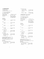
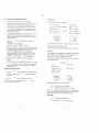
lnternationalElectricalSymbols
C a u t i o n !R e t e r t o t h i s m a n u a l b e f o r e u s i n g t h e m € t e r
Meter is protected by Reinforced or Double Insulation
CONTENTS
PAGE
1 INTRODUCTION.
1. 1 I n s t r u m e nFt e a t u r e s
2
3
2 SPECIFICATION.
2 . 1 E l e c t r i c aDl a t a
2 . 2 G e n e r aD
l a t a. . . . . .
A
4
8
3 OPERATING
I N S T R U C T I O N S. . . . . . . . . . 1 0
3 . 1 R o t a r yS w i t c h/ K e y p a dS e l e c t i o n s . . . . . . 1 0
J.Z
V o l t a g eM e a s u r e m e n. t. . . . . . . . . .
.
11
3 . 3 C u r r e nM
t e a s u r e m e n t . . . . . . . . . .. . .
3 . 4 W a t t s/ V A / P F / k W H rm e a s u r e m e n t s .
3 . 5 W 3 AM / P F/ k W H m
r easuremenrs..
I J
. A
t a
J.O
F r e q u e n c/yT H D M e a s u r e m e n t
to
3 . 7 SetUp
3 . 8 -t nv fvl . . . . . . . . .. . .
3.9 vvrrLvv
19
4 SAFETY
20
17
17
5 B A T T E R YR E P L A C E M E N T . . . . . . . . .
a1
L
I
6 WARRANTY
22
7 O T H E RP R O D U C T S
23
( (
Issue6 03/00
1. INTRODUCTION
The advanceddesignensuresreliableand accurate
measurements
undera wide range of operating
conditions.Measurement
featuresinclude:
.
Non-intrusive
AC/DCcurrent
.
True RMS, CrestFactorand THD for complexand
distortedwaveforms
.
Volts/ Watts/ VA / PF / kWHr
.
3 Phasemeasurements
.
ScreenSAVE mode
.
M l N ,M A X ,A V E .R E C M o d e
.
Internaland PC Datalogging.
.
Multiparameterand waveformdisplaymodes
Additional Features5333
.
Liveharmonicsanalysisand display
.
Ripplemeasurement
r
Extendedmemoryfor data logging
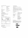
1.1 InstrumentFeatures
The mainoperatingfeaturesof the instrumentare as
f o l l o w s .S e e F i g .1 .
(1)
(2)
Clamp-onlaws for currentmeasurement
Jaw openinglever
(3)
Rotaryswitchfor functionselection
D o t m a t r i xL C D
l4l
(5)
(6)
(7)
Screencursorcontrol
REC mode
Backlight
(B)
Oscilloscope
/ Harmonicsmode
H O L Da n d S E T E C T
( 1 0 ) Z E R O A m p sZ e r o
(11) SAVE. Screensave mooe
( 1 2 ) N u m e r i cd i s p l a ym o d e
(9)
( 1 3 ) a n d ( 1 4 ) T e s t e a di n p u t e r m i n a t s
( 1 5 ) D i g i t aol u t p u l
'T-.,
Conformsto the latestinternational
directives
and
standardsconcerningsafetyand electromagnetic
compatibility.
.
EuropeanLow VoltageDirective73l23lEECand
93/68/EEC
.
EuropeanEMC DirectiveB9/336/EEC
and
93i6BiEEC
.
Submittedfor approvalto UL 3111-1
Safety Standards
'1992-09
IEC 1010-'1
:
Safetyrequirements
for electrical
equipmentfor measurement,
controland laboratory
use
Pafi.2-032:1994-12Particular
requirements
for hand
held currentclampsfor electricalmeasurement
and test
Part2-031:1993-02Particular
requirements
for hand
held probeassembliesfor electrrcal
measurement
and
600V Cat lV (750Vcat lll) Pollutiondegree2
EMC Standards
RF Susceptibility
EN 50082-1: 1992 3Vlm Residential,
Commerciat
and
LightIndustry
RF Emission
E N 5 0 0 8 1 - 11. 9 9 2 R e s i d e n t i aCt ,o m m e r c i a l
and LightIndustry
F C C P a r t1 5 C l a s sB
'Requires
optional
WrnLog
accessory
'\.
-,/'
' ---
5
6
7
8
I J
F i g .1
InstrumentFealures
1
2. SPECIFICATION
DF (Distortion
Factor)
1 % . : .D F < 1 0 0 % . .
t 3% rdg t 5 dgts
100%.. CF < 600%
I 5% rdg t 5 dgts
R e s o l u t i o n . . . . . . . . . . . . .0. 1 %
2.1Electricaldata
(Allaccuracy
s statedat 23.Ct 1"C)
H 0 1a l h , , n .H- :1 3 . . . .
H 1 3 . 1 h " ,:,H 2 5 . . .
2 . 1 , 1C u r r e nm
t easurement
( D C ,D C R M SA, C R M S )
M e a s u r i nrga n 9 e . . . . . . . . . . . . .0. .- 20004 DC or AC pk
A u t o r a n gfea c i 1 i t y . . . . . . . . . . . .4. .0 A / 4 0 0 4 / 2 0 0 0 4
Resoluiion......
1OmAin 40A range
1 0 0 m Ai n 4 0 0 4 r a n g e
1 A i n 2 0 0 0 4r a n g e
Accuracy
R M Sa n d D C
| > 1 0 A . . . . ... . . . . . . . . . . t 1 5 % r d g r 5 d g t s
| < 10A........,.
r 0.2A
AVE
| > 1 0 A . . . . . . . .......... . . . t 3% rdg t 5 dgts
| < 1 0 A . . .. . . . . .
I05A
t 5% rdg t 2 dgts
t 1 0 %r d gr 2 d g t s
All measurements
up to 251',
harmonic
FrequencyrangeF,, 45Hz to 65Hz
'10A,
1".,.,>
16",:. 10% 1".,,,,.
2 . 1 . 2 V o l t a g em e a s u r e m e n t
0 - 750V DC or AC
4Vt40Vl400v/750V
1 m Vi n 4 V r a n g e
1 O m Vi n 4 0 V r a n g e
1 0 0 m Vi n 4 0 0 Vr a n g e
1 V i n 7 5 0 Vr a n g e
PK
| > 10A ..........
| < 10A ..........
AHT
| > '1OAHr.........
l< 1OAHr.........
+
:
F,o/- rd^
J /U IUV
!
A
A i^l^
J UgTJ
t lok rdg r 5 dgts
r 0.5A
r 0.02v
! 2'k rdg r 5 dgts
I 0.sAHr
t 3% rdg t 5 dgts
t 0.03v
CF (CrestFactor)
1<CF<3.......
t 3% rdg t 5 dgts
3sCF<5....... ... t5%rdgr5dgts
R e s o l u t i o.n. . . . . .
001
R P L( R i p p l e )
2 % R P L <1 0 0 % . . . . . t 3 9 0r d g: 5 d g t s
1 0 0 o k . R P L <6 0 0 % . . . . x 5 % r d gt 5 d g t s
Resolution
0 1%
loc> 5A, lrc > 2A
A l lm e a s u r e m e nD
t sC a n d 1 O H zt o 1 k H z .
M a x i m u mo v e r l o a d1 0 , 0 0 0 4o r
RMS x frequency< 400,000 Amps RMS
is a lrue RMS measurement
(AC + DC)
Harmonics
THD (TotalHarmonicDistortion)
+ ?0.1 % . T H D< 1 0 0 %
.d^
r^rr+ rA u
grJ
1 0 0 9 " . T H D < 6 0 0 o , o.
1590rdgt 5 dgts
Resolution
01%
t 5% rdg r 5 dgts
r 0.03V
t 3% rdg t 5 dgts
! 5% rdg t 5 dgts
0.01
R P L( R i p p t e )
2o/<
o R P I < 1 0 0 %. . . . . . . . r 3 % r d gr 5 d g t s
1 0 0 o k .R p L <6 0 0 % . . . . t 5 % r d gt 5 O g t s
Resolution......
A.1o/a
VDc> 0.5V.Vi:_'. 0.2V
All measurements
DC and 10Hzto 1kHz.
M a x i m u mo v e r l o a d1 , 0 0 0V R M S
Volts RMS is a true RMS measurement
(AC + DC)
Harmonics
THD (TotalHarmonicDistorlion)
1 o / o . T H D< 1 0 0 % . . . . . . .r . 3 % r d g t 5 d g t s
100%< THD < 600%... t S% rdg t 5 dgts
Resolution.......
O.1o/o
DF (Distortion
Factor)
l o k ' -D F < 1 0 0 % . . . .
100%<cF<600%
Resolution
H O 15 V n " , , <H 1 3 . . .
H13<Vn",.:H25..
I 396rdg t 5 dgts
t 5% rdg I 5 dgts
01%
t 5% rdg t 2 dgts
+ 1no/^ r.ld
+ )
2 . 1 . 6P o w e r F a c t o r( S i n g l ea n d 3 p h a s e )
M e a s u r i nrga n g e0 . 3c a p . . 1 . 0. . 0 . 3i n d
( 7 2 . 5 'c a p 0 ' . 7 2 5 " i n d )
Resolution
0.01
Accuracy
i3"
.l^ta
2 . 1 , 7K i l o w a t tH o u r ( k W H r )
All measurements
up to 25'''harmonic
FrequencyrangeF6 45Hz to 65Hz
V"",,,"r' 1V, Vr",",;' 10% V,",,""
M e a s u r i nrga n g e. . . . . . . . . . . . . .4. 0 , 0 0 0 k W H r
A u t o r a n gfea c i | i t.y.. . . . .. .. . ... 4 k W H r4, O k W H r ,
2.1.3 Watts measurement(Singleand 3 Phase)
( D C ,D C R I / S .A C R N / S )
Resolution
M e a s u r i nrga n 9 e . . . . . . . . . . . 0 - 1 2 0 0 k W
D Co r
A u t o r a n g i nfga c i l i t y. . . . . . .
Resolution......
Accuracy........
wlz < 2kW,
w3a < 4kw
8sOKW
AC
4 k w ,4 0 k w ,4 0 0 k w ,
1200kw
1 Wi n4 k W
1 0 Wi n4 0 k W
100Win 400kW
1 k Wi n 1 2 0 0 k W
)
4o/^ rdn
+ 6 .ldfa
t 0 . 0 8k w
t 0.25kw
2 . 1 . 4 V A m e a s u r e m e n(t S i n g l ea n d 3 P h a s e )
( D C ,D C R M S A
, CRMS)
M e a s u r i nrga n 9 e . . . . . . . . . . . . .0-'12OOkVA
...
DC or
850KVAAC
A u t o r a n g fea c i 1 i t y . . . . . . . . . . . .4kvA,
...
40kvA. 400kvA
1200kvA
Resolution.......
1VA in 4kVA
1OVAin 40kVA
100VAin 400kVA
lkVA in 1200kVA
A c c u r a c y V A > 2 k V A . . . . . . + 2 ^o,^ rd,^ + q d^lc
v A < 2 k v A . . . . . . J 0.08kvA
2 . 1 . 5V A R M e a s u r e m e n(tS i n g l ea n d 3 P h a s e )
M e a s u r i nrga n 9 e , . . . . . . . . . . . .O. . BsOKVAR
A u o t r a n gfea c i 1 i t y . . . . . . . . . . . .4. K
. VAR.4OKVAR.
4OOKVAR.
S5OKVAR
Resolution.......
lVAR in 4kVAR
1OVARin 4OkVAR
100VARin 400kVAR
IkVAR in 850kVAR
Accuracy VAR > 4kVAR t 2.5% rdg 1 5 dgts
VAR < 4KVAR r 0.25kvAR
PowerFactorrange......,...
0.3<PF<0.99
4 0 0 k W H4r ., 0 0 O k W H r
4O,000kwHr
l W H ri n 4 k W H r
I O W Hirn4 0 k W H r
1OOWH
i nr4 0 0 k W H r
l k W H ri n4 . 0 0 0 k W H r
1 0 k W Hi n
r 40.000kWHr
A c c u r a c yk W H ' > 2 k W H r . . . r 3 9 6a g f , g t 5
k W H r <2 k W H r . . . .1 0 . O B k W H r
All measurements
F r e q u e n crya n g e. , . . . .
. . D C a n d 1 0 H zt o l k H z
C u r r e nrla n 9 e . . . . . . . . . . . . 10Ato 14004R|VS
V o l t a g rea n 9 e . . . . . . . . . . . .. '1Vto 600V RN/S
Maximum
i n p u t . . . . . . . . . . 600V Rl\4S/ 20004 pk
M a x i m u mo v e r l o a d . . .
1 0 0 0 vR M S/ 1 0 , 0 0 0 4
2 . 1 . 8 F r e q u e n c ym e a s u r e m e n t
(FromCurrentor Voltagesources)
M e a s u r i nrga n g e. . . . . . . . . . 1 O H zt o l k H z
Resolution
.
A c c u r a c y4 0 , 7 0 H 2 . . , . . .
1 0- 1 0 0 0 H 2 . .
C u r r e nRl a n g e . . . . . . . . . . . ...
VoltagR
e a n g e. . . . . . . . . . . . .
01Hz
t 0 . 5 %r d g
! 1okrdg
10Ato 14004RI\4S
1 V t o 6 0 0 VR M S
2 . 1 . 9S c o p e F u n c t i o n
2 . 1. 9 . 1C u r r e nm
t easuremenl
R a n g e.s. . . . . . . .
10tu20A/40A/100A
200tu400AJ1
000A/2000A
Resolution
1Ain 40A
1 0 Ai n 4 0 O A
50A in 20004
Accuracy
t 3% rdg r 1 pixel
Maximum
o v e r 1 o a d . . . . . . . . .1. 0. ., 0 0 0 4
2.1.9.2Voltagemeasurement
Ranges
2 . 2 . 3E n v i r o n m e n t a l
Accuracy........
4Vt10Vt20Vt40Vl100V
200v/400v/1000v
1 0 0 m Vi n 4 V
1Vin4OV
1 0 Vi n 4 0 0 V
3 1. 2 5 Vr n ' 1 0 0 0 V
! 2ohrdg + 1 pixel
M a x i m u mo v e r l o a d
.........
l O O OR
VMS
^
.
'
Kesotuuon.......
..
D C a n d 1O H zt o 6 0 0 H 2
T i m eb a s e . . . . . .
2 m s . 4 m s 1, O m s ,
50msidiv
R e f r e s rha t e . . . . . . . . . . . . . . . . . .0. . 5 s e c o n d s
F r o n r r e n n r r r' "r n" vn o
"
F O R I N D O O RU S EO N L Y
Referenceconditions.All accuracy,s
statedat
,4.'a
+ 1oa
Operatingtemperature
O"Cto 50.C (32.Fto 122"F)
Temperalure
coeff.of current< t0.15% of rdg per.C
Temperalure
coeff.of voltage< t0.15% of rdg per .C
Maxim^umrelative
humidity80% for lemperatures
up to
3]:9 (-87:f) decreasingtinearty
to 50?6retativehumidiry
at40'c (104'F)
Maximumoperatingaltitude2OO0m
2.2.4Mechanical
Dimensions
RS-232 Interfaceto a PC
9600baud 1 startbit B data bits '1stop bit
RequiresWinLog interfaceand software
2.2 GeneralData
2 . 2 . 1D i s p l a y
B a c k l idt o t m a t r i xL C D 1 6 0 x 1 2 8 .
il
n
H
2?=.2
200.E
315 E
t 414
3 5.5
F t l i
Fl
Fl,ll
Hts.
tr!
T = t : :
I
'...
'-.--.---
nr,,1
f 1 I f , i q . 5 !
H r r E : t j . . a n
l l i
' . = , .
2.2.2Power Supply
Batterytype 1.5VAlkalineAA MN 1500or IEC LR6 x 6
Batterylifetypically
24 hou.s(backlightoff)
1 2 h o u r s( b a c k l i g hotn )
..
L e n g t h3 0 0 m m( ' 1 2i n c h e s )
W i d t hg S m m( 3 . 7 5i n c h e s )
Depth52mm(2 inches)
Weightinc. batteries.. . . B 2 0 g / 1 B l b s .
Case material
.. BayblendTB5MN
J a wo p e n i n g
. 60mm
J a wc a p a c i t y . . . . . . . . . .... . . .58mmdiameter
2 . 1 . 1 0D i g i t a lo u t p u t
A c c e s s o r i e s . . . . . . . . . ..
. . . . Voltage
..
probes
Carryingcase
Operator'smanual
Cleaning
. The unitcan be cleaned
withan lsopropanol
impregnated
cloth.
Do not use abrasivesor
othersolvenls.
2.2.5 Power-up
At power-upthe followingscreenis displaved
for 5
secondsindicating
the batterystat.Ls.The remainino
batterylifetimeis displayed.
withand withoutthe
backlight Whenthe displaychangesto the digital
mode,the instrument
is readyfor use.
3 . O P E R A T I N GI N S T R U C T I O N S
SAVE Mode
This functionallowsthe captureof up to B screens
whrchcan be eitherwaveformsor numericaldata. For
the 5333 bothwaveiormand harmonicsscreensare
capturedsimultaneously
in one memorylocation.
Pressingthe SAVE modekey bringsup the followinq
texton the screen:
l n t e r n a t i o n aS
l ymbols
l T o o r t a n rI n { o r m a r r o r
( S e eM a n u a l )
D o u b l el n s u l a t r o n
A
EI
3.1 Rotary Switch / Keypad selections
1
The instrument
functionsare selectedby a rotaryswttch
and an B key keypad.The rotaryswitchpositionsare as
iollows.
OFF
Voltage
Current
nz
w3z
Frequency/ THD
Power
3 phasePower
Set up
OptionsMenu
Log
LoggingN,4enu
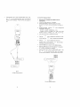
3.2 Voltage measurementof RMS or DC Voltaqe
SAFETYWARNTNG
Whenswitchingthe instrument
ON, waitfor the auto
calabration
lo finishbeforetakingmeasurements.
To avoid possible electric shock and
to the instrument, do not attempt to
any voltage that might exceed the maximum
range of the instrument - 600Vrmsand lkHz
The pushbuttonkeysare as follows:
2
Movethe rotaryswitchto the V position.
Insertthe test leadsintothe socketson the frontof
the instrument.Connectthe red leadto the V
terminal,and the blackleadto the COM terminal
Applythe test leadsto the circuitundertest and
readthe displayedvoltage.See Fig.2.
- 6
8
.
i
2
3.
/
5
6
7
B
Optroncursormovementand screenchanger
HOLDand Optionselect
R E C m o d e( M i n ,M a x .A v )
ZERO
.
,
BacklightON / OFF
SAVE
Oscilloscope/Harmonics
(5333)mode
NumericDisplaymode
10
8
Use the l.I'
key to movethe cursorand the
HoLD
-J key to selecteitherSAVE,RECOVERor
CLEAR Repeatthis processto selectone of the SAVE
locationsfrom 1 to B.
The wholescreenis savedin the selecledlocationand
can be recoveredat a later date - even after the
instrumenthas beenpoweredoff. A secondpressof
the SAVE key returnsthe instrumentbackto the normal
modeof operation.
Instrument
off
A
SAVE RECOVER CLEAR
2
3
4
5
6
7
Use the I
key to changethe parameters
displayed
Screen1 = V DC, V RMS (AC + DC)
S c r e e n2 ( 5 3 3 2 )= V R M S ,V A v . V p k , V C F , V
nz
S c r e e n2 ( 5 3 3 3 )= V R N 4 SV, A v . V p k , V C F ,V R p l
Use lhe HOLD key to freezethe display.
'= lrr"
Use the
key to displaythe waveformof the
voltageand 16s -:--- key to changethe timebase
!: lr'r'
,
key to displaythe harmonic
--contentof the voltageand the
key to select
i n d i v i d u ahla r m o n i c(s5 3 3 3o n l y )
,
Use the BBB8key to returnto the digitaldisptay.
Use the
11
Use the REC key to enterthe RECORDmode.Use
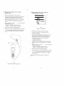
3.3 Current measurement
169 i*1
key to showthe MAX,MlN. AVE disptays
of the screenreadings.Pressthe REC key againto
exit.
.
-F-
o
o
r
L
[r -i<{'
.i
\\
i ;
F
!
.
\-
\ '
Readthe display.Usethe *l
keVto chanqethe
parametersdisolaved.
S c r e e n1 = A D C ,A R M S ( A C+ D C )
S c r e e n2 ( 5 3 3 2 )= A R M S ,A A v , A p k . A C F ,A H z
S c r e e n2 ( 5 3 3 3 )= A R I \ 4 SA, A v , A p k , A C F ,A R p l
Use the HOLD key to freezethe display
Use the
I
l -
r \\,r-\-/
- A
t6t
If
Jl
i c=).-=l
,_
I
El tl ttal
*1""
key to disptaythe waveformof the
currentand the -:key to changethe timebase.
J
)
I
Remove any Voltagetest leads from the
instrument.
Movethe rotaryswitchto A position.
Pressthe triggerto openthe jaws and clamp
aroundthe currentcarryingconductoras shownin
Fig.3
Use the
+1""
key to displaythe harmonrc
-contentof the currentand the
key to select
individualharmonics(5333only)
Use the 88BBkey to returnto the digitaldisplay
Use the ZERO key to zerothe displayif necessary
or if relativereadingsare required.
Use the REC key to enterthe RECORDmode. Use
the key to showthe MAX,MlN, AVE values
of the screenreadings.Pressthe REC key lo exit.
(
b
Fig 2
VoltageMeasurement
CurrentMeasurement
I J
3.4 Measurementof Watts / VA / PF / kWHr
( S i n g l eP h a s e )
o
o
.
3.5 Measurementof W / VA / PF / kWHr in a
b a l a n c e ds y s t e m ( 3 P h a s e )
Movethe rotaryswitchto the W position.
-
r
L.l
Insertthe tesi leadsintothe socketson the frontof
the instrumenl.Connectthe red leadto the V
terminal,and the blackleadto the COM terminal.
.
PTessthe triggerto openthe jaws,and clampthem
on the currentcarryingconduclor,as shownin
Fig.4.
-Readthe display.Use the
key to changethe
parametersdisplayed.
Screen1 = kVA,kW. kVAR,PF. kWHr
S c r e e n2 = V R M S ,A R M S ,k W , P F ,A H r
a
Use the HOLD key to freezethe display
LI
L 1
Fig 5
U1e_the
REC key to enlerRECORDmode Use the
Watts3Z Configuration
key to show the MAX, MlN,AVG displaysof
the screenreadings.Pressthe REC key againto
exit.
Movethe rolaryswitchto the W3Z position.
A screenprompt,Fig.5, indicatesthe above
methodof conneclion.
Insertthe test leadsintothe sockelson the frontof
the instrument.Connectthe red leadto the V
terminaland the blackleadto the COM terminal.
.
Applythe test leadsto the circuitundertesl:
Red leadto PhaseL2
Blackleadto PhaseL3
Pressthe triggerto openthe jaws and clampthem
aroundthe currentcarryingPhaseL1, as shownin
Fig 5.
Readthe display.Use the ' - | key to changelhe
parameters
displayed.
S c r e e n l= k V A ,k W , k V A R ,P F , k W H r
S c r e e n 2= V R M S ,A R M S ,k W , P F ,A H r
.
Use the HOLDkey to freezethe display.
.
Use the REC key to enterRECORDmode. Use the
1 1- key to showthe MAX.
MlN, AVE displaysof
the screenreadings.Pressthe REC key againto
exit this mode.
W3Z giveslhe totalpowerbasedon a balanced
system.
Fig 4
Single Phase Watts Measuremenr
II
3 . 6 F r e q u e n c y/ T H D M e a s u r e m e n t
.
Movethe rotaryswitchto the Hz position.
.
Insertthe test leadsintothe socketson the frontof
the instrument.Connectthe red leadto the V
t e r m i n aa
l ,n d t h e b l a c kl e a dt o t h e C O M t e r m i n a l .
To measurethe frequencyof the voltagesupply
applythe test leadsto the circuitas shownin Fiq.2
and readthe displsy.
.
.
.
.
.
To measurethe frequencyof the current,pressthe
lriggerlo open thejaws.and clampthemon the
currentcarryingconductor.as shownin Fiq.3 and
readthe display.
Use the
key to changethe parameters
displayed.
Screenl=Hz,ACRMS
S c r e e n2 = H z ( F " )A, C R M S .T H D ,D F
Whenconfiguredto measurepower(Fig.4) withthe
test leadsconnectedand the jaws clampedarouno
a currentcarryingconductor,lhe instrument
displaysthe frequencyof the currentsource
( p r o v i d i nAgR I U S> 1 0 A ) . l f A R M S< 1 0 A ,a v o l l s
frequencymeasurement
will be made (providing
VRMS> 1V),otherwise---.-wiltbe displayed
Pressthe HOLD/ ZERO buttonto freezethe
display.
3 . 7S e t U p
The followingscreenis displayed:
CONTRAST
XXXXXXXX
AUTO POWER DOWN
O N o rO F F
R A N G I N G
O N o rO F F
LOW PASS FILTER
PF DISPLAY
O N o rO F F
t---r
I rF-r
DEGoTCOSU
t - * -|
| f|
I
{-Jl
I
l + l
SELECT
C H A N G E
L O W P A S SF I L T E R( O t t t =
1 - 1 2 0 Ui o c t a v e F
, >100H2
Defaultsettingsare shownin bold.
The keysare usedto makeselections
from the menu.
3 , 8L O G
Two modesof data loggingare available:
eitherlogging
lo an internalnon-volatile
memoryor loggingto an
externalPC, using the digitaloutputlead.
Selectionof the rotaryswitchposition'LOG'bringsup
the followingmenu:
.
Use the REC key to enler RECORDmode. Use tne
-- t "y to showthe MAX,MtN,AVE displaysof
.
the screenreadings.presslhe REC key againto
exitthis mode.
Additional features 5333
r- lrrr'
.
Use the
key to displaythe waveformof the
.current/ voltageand the r.
key to changethe
timebase.
.
Use the
OPTIONS
LOG
E N A B L EL O G
DISPLAYDATA
O F F< O N >
S E N DT O P C
ll r+- rl
^- lrt'
key to dasplay
the harmonic
contenlof the currenVvoltage
-. key to
and the
s e l e c it n d i v i d u ahla r m o n i c s
I N T< P C >
S E TT I M E
l-r i
I
SELECT
CHANGE
Detaileddescription
is as givenbelow.
INT Indicalesinternallogging
PC Indicatesexternal(to a PC) logging
In PC mode.data is continually
sentto the digitaloutput
and is not loggedwithinthe instrument.Logsall the
parametersshownon lhe instrument
display.
S E TT I M E
*-'o'o J
to
Increments
the seleclion
Mou". on to the nextselection
17
It
For easeof operalionif the currenttime is chanqed,
then the sta.tis automaticaily
resetto this time i 60
minutes,and the end time is set to the starttime + 60
minutes.The minimumsampleintervalis .1second,
a n dt h e m a x i m u ms a m p l et h o u r . A 2 4 h o u rc l o c ki s
used.
Start/ Stopand loggrnginlervalscan be selectedas
requrred.
CURRENT
START
END
TIIVE
TIME
TIME
S A M P L EI N T E R V A L
EXIT
On the chartdisplayscreenthe singleparameteris
shownvs time,and an EXITis displayedon the screen
allowinglhe userto returnto the loggingparameter
selectmenu.
lFl
t_tlt 5Er r=
I1
HR:MIN
HR:MIN
iltl
HR:MIN
MIN.SEC
The maximumnumberof pointsthatcan be loggedis:
5332= 2000 readings,1000setsol 2 or 400sels of 5
5 3 3 3= 5 0 0 0r e a d i n g s , 2 5 0 0
s e t so f 2 o r 1 0 0 0s e t so f 5
The maximumloggingdurationis determinedbv the
batterylife (24hrs) and the memory. Databeinglogged
is an averageover the sampleperiod.
E N A B L EL O G
The loggingfunctioncan be enabledfromthe mainlog
menu.The low balterysymbolflashesif thereis
insufficient
batterylifeto completethe logqingsession
definedin the SET TIME menu.
When internalloggingis enabtedthe loggingwill
commencewithin5 secondsof selectingthe
-measurement
screenwiththe rotaryswitchand r
key. All data displayedon the selectedscreenwill be
logged.'MEMORY'flashesif thereis insufficient
memoryto completethe loggingsessiondefinedin the
SET TIME menu. Oncelogginghas commencedan on
screentimercountsdownthe remaininglogginoperiod.
Loggingwillterminateif lhe screendisplayis changed
throughmovingthe rotaryswitchor pressingthe ' 1tey beforethe end of the loggingsession.
lf PC loggingis enabled,all measurements
appearing
on the inslrumentdisplaywillbe loggedto the pC.
Loggingwill not terminateif the screenis chanoed.
DISPLAYDATA
On entryto lhis menu a listof the parameters
which
'h a v eb e e nl o g g e da r e d i s p l a y e dT. h e
key
'o'o
J
increments
throughthe list,and the
kev selects
O N E p a r a m e t ef ro r d i s p l s yF o re x a m p l e :
ARIVS,AAv,APk,ACF
EXITreturnslo the previousmenu.
t'lIf{lE.:u
FilE :t:1.tlB
FF:Egg {r
:r: . El
T
The followinginformalion
is alsodisplayed:
LOGGING
DURATION
T= HR:MlN
S A M P L EI N T E R V A L
\ = MIN SEC
MIN MAX AVE
S E N DT O P C
This allowslhe userto downloaddatato a PC runninc
lhe WinLogprogram.Previously
the user musthave
selecled"DOWNLOADLOG"fromthe Instrr-rment
optionwithinthe WinLogprogram.
On selectionof SEND TO PC the textwillflashuntilall
data has beendownloaded
to the PC.
3.8WinLog
WinLogis the PC residenlsoftwarefor the new 5332&
5333PowerMeters.The softwareis usedto continuarry
log electricalpowermeasurements
or downloadstored
dala to a PersonalComputerfor furtheranalysis
'-]J1
x',rra,. iiir
ft,|!.i)f)',
-@n!q
il;n
3hrvd"! [:l$-
_
Pft*nt
*J
. _ , i
rlDa L.mn J;
k qtdrr
Fig.7 Winlog Software
1B
19
.
Keyfeaturesinclr-rde.
.
.
.
.
.
.
Maximum Safe Voltage
Easyto use Windowsformat
Datapresentation
in displaymimic.tableand
chartmodes
Waveform,harmonicsand datadownload
Harmonicsanalysisof waveforms
Loggingof up to 5 parameters,
waveformsand
harmonics
Sirnpleexporlingof data and trendsinlo other
applications
4. SAFETY
.
Voltage:-600V MAXIN,lUM
AC RMS or DC betweenlive
conduclorand ground.600V MAXIMUMAC RMS or DC
betweenV and COM terminalsand a maximum
frequencyof 1kHz
lmportant Information
.
The instrumenthas beendesignedto complywith
l E C 1 0 1 0 - 2 - 0 3I n2s t a l l a t i oCna t e g o r lyO v e r v o t t a o e
CategoryllV 600V Pollutiondeqree2 and
U L 3 111 - 1. C o n f o r m w
s i t ht h eE E C L o wV o l t a o e
Directive73l23tEECand 93/6BrEEC.
IEC 1010is a safetystandardwhichhas the followinq
features:
o
Current :- 600V MAXIMUMAC R[/S or DC between
uninsulaled
conductorand groundand maximum
frequencyof 1kHz. This limitation
appliesto unisulaled
conductorsonly.
Installation
categoriesI to lV relatethe maximum
workingvoltageto overvoltage
transienlsthatcan
be expectedin the measuringenvironment.60OV
CAI lV, the maximumexpectedtransientsmustnot
exceedBkVpeak.
In a pollutiondegree2 environment
the internal
designof the instrumentcan copewithtransient
conductivities
due lo condensation.
Safe operation of the instrument is the
responsibilityof the operatorwho must be suitably
qualifiedand/or authorised.Users of this equipment
and or their employeesare reminded that Health
and Safety Legislationrequiresthem to carry out
valid risk assessmentsof all electricalwork. so as
to identify potential sources of electricaldanger and
risk of electrical injury such as from inadvertent
short circuits. Where the assessmentsshow that
the risk is significant,then the use of fused test
leads constructed in accordancewith the HSE
guidance note GS38 'ElectricalTest Equipmentfor
u s e b y E l e c t r i c i a n si's a d v i s e d .
lf the instrumentis usedin a mannernot specifiedbv
the manufacturer.
thenthc protectionprovidedbv the
equipmenlmay be impaired.
20
.
The instrument is intendedfor indoor use only.
Do not attemptto take any measurement
of current
or voltagehigherthanthe maximumrangeof the
inslrument.
.
The unil is not hermetically
sealedand shouldNOT
be broughtintocontactwithsurfacewater.
.
Frequently
inspectthe test leadsand the instrument
for damage. lf the instrumentis physically
damaged
or does not functionproperly,it shouldnot be used.
USE ONLY SUITABLYRATEDVOLTAGETEST
L E A D ST O I E C 1 0 1 0 - 2 - 0 3 1( 6. 0 0 VC A T t V P o i l u t i o n
Degree2).
5. BATTERY REPLACEMENT
Replacement
withotherthanthe specifiedbatterieswill
invalidate
the warranty.
F i to n l yB a t t e r yT y p e1 . 5 VA l k a l i n eM N 1 5 0 0 I, E CL R 6o r
e q u i v a l e nxi 6 .
willappearon the LCD displayto indicatethatthe
E
minimumoperatingbatleryvoltagehas beenreached
SAFETYWARNING
Before removing the battery cover, make sure
that all externalvoltages are disconnected
from the instrument. For certainty remove all
leads and unclamp the instrument.
To changethe batteries.
see Fig B
o Swilchoff the instrument
.
Undothe retainingscrews(A and B) on the battery
coverand lifl the coverclearof the unit.
.
Replacethe usedbatteries
.
Ensurethe batterycoveris replacedand the locking
screwstightened,beforefurtheruse.
21
,I
'r
\(
I
\I . i r lI
'
i @|
- :| : : -
l
i
lo
,
l
l
/
l , l
i
\\
,
H
i
o\
'/ l -a - -o'
' ! -
I
l
I
l
\ -
1
\
l u l
lrl
l l t lll
l-L
\AT )
i t
I
I
I
\
,^ |
|
' |r
l \
I
I
l
l
F
,
I
I
( l
,--:^
i
\ - l - /
Fig B
BalteryReplacement
6. WARRANTY
Your clampon powermeteris guaranteedfor one year
from the date of purchaseagainstclefective
malerialor
workmanship. lf the meter fails dr.rringthe warranry
period,we shall at our discretion,repairor replaceit
with a new or reconditionedunit provided we are
satisfiedthat the failureis due to defeclivematerialor
workmanship.
To make a claim under warranty,the metershouldoe
returnedto us, poslage prepaid,with a descriotionof
the defect The use of batteries,other than lhar
specifiedinvalidates
thiswarranty.
Goods allegedby the buyer to be defecliveshall not
form the subjectof any claimfor injury,loss,damage,or
any expense howsoever incurred whether arisino
directlyor indirectlyfrom such alleqed defects othei
than death or personalinjuryresultingfrom the seller's
negligence.
No conditionis made or to be implied nor is any
warrantygiven or to be impliedas to the life or wear of
goods suppliedor lhat they will be suitablefor any
particularpurposeor for use under specificconditions.
notwithstanding
that such purposeor condilionsmay be
m a d ek n o w nl o t h e s e l l e r .
22
1t
7. OTHER PRODUCTS
B&K Precisionoffersa widerangeof instrumentation
for
the measurement
and analysisof current,voltageand
power.Visitwww.bkprecision.com
to viewthe wholelirre
of B&K products.
B&K Precision'spolicy is one of continuous
product improvementand the company reseryes
the right to revise the above specificationswithout
notice.
ll
DECLARATION OF CONFORMITY
E q u i p m e n tN a m e / T y p eN u m b e r : 5 3 3 2& 5 3 3 3
M a n u f a c t u r e r . L E I VH E M EL I M I T E D
Address:
1 PenkethPlace,Wesl Pimbo,
Skelmersdale,
Lancashire,
WNB gQX.
UnitedKingdom
EuropeanStandards:EMC
E N 5 0 0 B 2 -:11 9 9 2G e n e r i cl m m u n i t S
y tandard.
Part 1. Residential,
commercialand light
industry.
E N 5 0 0 8 1 -:1' 1 9 9 2G e n e r i cE m i s s i o n
Standaro.
Part 1. Residential,
commercialand light
industry.
S a f e t y B S E N 6 ' 1 0 1 0:- 1 9 9 3G e n e r aR
l equirements.
Safetyrequirements
for electricalequipmentfor
measurement,
controland laboraloryuse:B S E N 6 1 0 1 0 - 2 - 0.3129 9 4 - 1 2P a r t i c u t a r
requirements
for handheldcurrentclampsfor
electricalrneasurement
and test.
B S E N 6 1 0 1 0 - 2 - 0:3119 9 3 - 1 2P a r t i c u t a r
requirements
for handheldprobeassemblies
for electricalmeasurement
and lest.
Description
of Equipment: AC/DCClampOn power
Meter.
I certifythal the apparalusidentifiedabove
conformsto the requirements
of CouncilDirectives:(1) Electromagnetic
Cornpatibility
Directive
B9/336/EEC
(2) LowVoltageDireclive73l23lEEC
(3) CE MarkingDirectiveg3/68/EEC
; n 1
.r"
Signed
Name
n^r^,
/1//
.'
/
L--
E R I N NN , lH O P K I N S
O P E R A T I O ND
SIRECTOR
9/9/98