1
UC-8112-LX-STK User’s Manual
First Edition, April 2015
www.moxa.com/product
© 2015 Moxa Inc. All rights reserved.
Reproduction without permission is prohibited.
UC-8112-LX-STK User’s Manual
The software described in this manual is furnished under a license agreement and may be used only in accordance with
the terms of that agreement.
Copyright Notice
Copyright ©2015 Moxa Inc.
All rights reserved.
Reproduction without permission is prohibited.
Trademarks
The MOXA logo is a registered trademark of Moxa Inc.
All other trademarks or registered marks in this manual belong to their respective manufacturers.
Disclaimer
Information in this document is subject to change without notice and does not represent a commitment on the part of
Moxa.
Moxa provides this document as is, without warranty of any kind, either expressed or implied, including, but not limited
to, its particular purpose. Moxa reserves the right to make improvements and/or changes to this manual, or to the
products and/or the programs described in this manual, at any time.
Information provided in this manual is intended to be accurate and reliable. However, Moxa assumes no responsibility for
its use, or for any infringements on the rights of third parties that may result from its use.
This product might include unintentional technical or typographical errors. Changes are periodically made to the
information herein to correct such errors, and these changes are incorporated into new editions of the publication.
Technical Support Contact Information
www.moxa.com/support
Moxa Americas
Moxa China (Shanghai office)
Toll-free: 1-888-669-2872
Toll-free: 800-820-5036
Tel:
+1-714-528-6777
Tel:
+86-21-5258-9955
Fax:
+1-714-528-6778
Fax:
+86-10-6872-3958
Moxa Europe
Moxa Asia-Pacific
Tel:
+49-89-3 70 03 99-0
Tel:
+886-2-8919-1230
Fax:
+49-89-3 70 03 99-99
Fax:
+886-2-8919-1231
Table of Contents
1.
Introduction ...................................................................................................................................... 1-1
Overview ........................................................................................................................................... 1-2
Model Descriptions .............................................................................................................................. 1-2
Package Checklist ............................................................................................................................... 1-2
Product Features ................................................................................................................................ 1-2
Hardware Specifications ...................................................................................................................... 1-3
Hardware Block Diagram ..................................................................................................................... 1-4
2.
Hardware Introduction...................................................................................................................... 2-1
Appearance........................................................................................................................................ 2-2
LED Indicators .................................................................................................................................... 2-3
Default Programmable Button Operations .............................................................................................. 2-4
Reset to Default Button ....................................................................................................................... 2-4
Real Time Clock .................................................................................................................................. 2-5
Placement Options .............................................................................................................................. 2-5
DIN Rail Mounting ....................................................................................................................... 2-5
Wall or Cabinet Mounting ............................................................................................................. 2-5
3.
Hardware Connection Description ..................................................................................................... 3-1
Wiring Requirements ........................................................................................................................... 3-2
Connecting the Power .................................................................................................................. 3-2
Grounding the Unit ...................................................................................................................... 3-3
Connecting to the Console Port ............................................................................................................. 3-3
Connecting to the Network................................................................................................................... 3-3
Connecting to a Serial Device ............................................................................................................... 3-4
Inserting the SD and SIM Card ............................................................................................................. 3-4
USB Port............................................................................................................................................ 3-5
Inserting a Micro SD Card .................................................................................................................... 3-5
Installing the Cellular Module ............................................................................................................... 3-5
Installing the Wi-Fi Module................................................................................................................... 3-7
4.
Remote Configuration and Management ........................................................................................... 4-1
Connecting to the UC-8112 via Webmin................................................................................................. 4-2
Configuring Webmin............................................................................................................................ 4-2
Change Language and Theme ....................................................................................................... 4-3
Webmin Action Logs .................................................................................................................... 4-3
Webmin Configuration.................................................................................................................. 4-4
Webmin Users........................................................................................................................... 4-16
Configuring System........................................................................................................................... 4-19
Bootup and Shutdown ................................................................................................................ 4-20
Disk and Network Filesystems ..................................................................................................... 4-20
Initial System Bootup ................................................................................................................ 4-21
Running Processes..................................................................................................................... 4-22
Scheduled Cron Jobs.................................................................................................................. 4-23
Software Package Updates ......................................................................................................... 4-24
Software Packages .................................................................................................................... 4-25
System Documentation .............................................................................................................. 4-25
System Log .............................................................................................................................. 4-26
Configuring Server ............................................................................................................................ 4-27
Apache Webserver..................................................................................................................... 4-27
DHCP Server............................................................................................................................. 4-28
Read User Mail .......................................................................................................................... 4-29
Configuring Others ............................................................................................................................ 4-29
Command Shell ......................................................................................................................... 4-29
File Manager ............................................................................................................................. 4-29
Configuring Networking ..................................................................................................................... 4-30
Bandwidth Monitoring ................................................................................................................ 4-30
Linux Firewall............................................................................................................................ 4-30
Network Configuration ............................................................................................................... 4-31
Hardware......................................................................................................................................... 4-32
Partitions and Local Disks ........................................................................................................... 4-32
System Time ............................................................................................................................ 4-33
Viewing More Options ........................................................................................................................ 4-33
View Module Logs ...................................................................................................................... 4-33
System Information ................................................................................................................... 4-34
Refresh Modules ........................................................................................................................ 4-34
Logout ..................................................................................................................................... 4-34
5.
Wireless Module Settings .................................................................................................................. 5-1
Enabling Cellular Module ...................................................................................................................... 5-2
Configuring the Cellular Module ..................................................................................................... 5-2
Configuring the Wi-Fi Module ............................................................................................................... 5-2
Bridging the Cellular to Serial Interface ................................................................................................. 5-4
UDP Server to Serial Device .......................................................................................................... 5-4
UDP Client to Serial Device ........................................................................................................... 5-4
TCP Server to Serial Device .......................................................................................................... 5-4
TCP Client to Serial Device ........................................................................................................... 5-4
Configuring the IPSec Settings ............................................................................................................. 5-5
6.
Data Acquisition ................................................................................................................................ 6-1
Acquiring Data ................................................................................................................................... 6-2
A.
Regulatory Approval Statements ....................................................................................................... A-1
1
1.
Introduction
Moxa’s UC-8112 Series Starter Kit is an ideal hardware and software package for system evaluation.
Containing a UC-8100 computer, optional cellular and Wi-Fi modules, and various software packages, this
compact Starter Kit helps users establish their system architecture in no time.
The following topics are covered in this chapter:
Overview
Model Descriptions
Package Checklist
Product Features
Hardware Specifications
Hardware Block Diagram
UC-8112-LX-STK Manual
Introduction
Overview
The UC-8112-LX Starter Kit offers a cellular or Wi-Fi module that users can easily install to establish wireless
communication between the UC-8100 and the peripheral devices. In addition, system integrators can easily
evaluate the result of remote management for some specific industrial tasks, such as data acquisition, and
system integration.
Model Descriptions
The UC-8112-LX-STK series includes the following models:
•
UC-8112 Starter Kit with LTE-EU: Compatible with LTE, HSPA, GPRS/GSM, GPS
•
UC-8112 Starter Kit with LTE-US: Compatible with LTE, HSPA, GPRS/GSM, GPS
•
UC-8112 Starter Kit with Wi-Fi: Compatible with IEEE 802.11b/g/n
•
UC-8112 Starter Kit
Package Checklist
Before installing the UC-8112, verify that the package contains the following options:
UC-8112-LX Computer Kit
•
UC-8112-LX computer x 1
•
Console cable x 1
•
GPS antenna x 1
•
Cellular antenna x 1
•
Wi-Fi antenna x 1
•
DIN rail mounting kit x 1
•
1 GB SD x 1
•
Power jack x 1
•
Power adapter x 1
Wi-Fi module kit
•
Wi-Fi module x 1
•
Wi-Fi antenna cable x 1
Cellular Module Kit
•
Cellular module x 1
•
Cellular antenna cable x 1
NOTE: Notify your sales representative if any of the above options are missing or damaged.
Product Features
•
ARMv7 Cortex-A8 300/600/1000 MHz processor
•
Dual auto-sensing 10/100 Mbps Ethernet ports
•
SD socket for storage expansion and OS installation
•
Rich programmable LEDs and a programmable button for easy installation and maintenance
•
Mini PCIe socket for cellular module
•
Debian ARM 7 open platform
•
Cybersecurity
1-2
UC-8112-LX-STK Manual
Introduction
Hardware Specifications
Computer
CPU: ARMv7 Cortex-A8 300/600/1000 MHz
USB: USB 2.0 host x 1 (type A connector)
DRAM: 256 MB DDR3 SDRAM (512 MB by request)
OS (pre-installed): Debian ARM 7 (Kernel 3.2)
Storage
Storage Expansion:
• SDHC/SDXC socket for storing OS and storage expansion
• 1 GB SD card with OS pre-installed
• MicroSD socket for storage expansion (UC-8112-LX/UC-8112-T-LX only)
• 2 GB MicroSD cards with OS pre-installed (UC-8112-LX/UC-8112-T-LX only)
Ethernet Interface
LAN: 2 auto-sensing 10/100 Mbps ports (RJ45)
Magnetic Isolation Protection: 1.5 kV built-in
Serial Interface
Serial Standards: 1 or 2 RS-232/422/485 ports, software-selectable (5-pin terminal block connector)
Console Port: RS-232 (TxD, RxD, GND), 4-pin pin header output (115200, n, 8, 1)
Serial Communication Parameters
Data Bits: 5, 6, 7, 8
Stop Bits: 1, 1.5, 2
Parity: None, Even, Odd, Space, Mark
Flow Control: XON/XOFF, ADDC® (automatic data direction control) for RS-485
Baudrate: Max. 921600 bps
Serial Signals
RS-232: TxD, RxD, RTS, CTS, GND
RS-422: TxD+, TxD-, RxD+, RxD-, GND
RS-485-4w: TxD+, TxD-, RxD+, RxD-, GND
RS-485-2w: Data+, Data-, GND
LEDs
System: Power x 1, USB x 1, SD x 1, signal strength x 3 (UC-8112/8162/8132 with cellular module)
LAN: 10M/100M on connector
Programmable: Diagnosis x 3
Switches and Buttons
Push Button: Initially configured to return a diagnostic report, and to reset the device to factory defaults
Physical Characteristics
Housing: Polycarbonate plastic
Weight: 224 g
Dimensions: 101 x 27 x 128 mm (3.98 x 1.06 x 5.04 in)
Mounting: DIN rail, wall (with optional kit)
Environmental Limits
Operating Temperature:
Standard Models: -10 to 60°C (14 to 140°F)
Wide Temp. Models: -40 to 75°C (-40 to 167°F)
Storage Temperature: -40 to 80°C (-40 to 176°F)
Ambient Relative Humidity: 5 to 95% (non-condensing)
Anti-Vibration: 2 Grms @ IEC 60068-2-64, random wave, 5-500 Hz, 1 hr per axis (without any USB devices
attached)
Anti-Shock: 20 g @ IEC 60068-2-27, half sine wave, 30 ms
1-3
UC-8112-LX-STK Manual
Introduction
Power Requirements
Input Voltage: 12 to 24 VDC (3-pin terminal block, V+, V-, SG)
Power Consumption: 5.4 W (without cellular module and external USB device attached)
• 450 mA @ 12 VDC
• 225 mA @ 24 VDC
Standards and Certifications
Safety: UL 60950-1, EN 60950-1, CCC (GB9254, GB17625.1)
EMC: EN55022 Class B, EN 55024-4-2, EN 55024-4-3, EN 55024-4-4, FCC Part 15 Subpart B Class A
Green Product: RoHS, CRoHS, WEEE
Reliability
Alert Tools: Built-in RTC (real-time clock)
Automatic Reboot Trigger: Built-in WDT (watchdog timer)
Warranty
Warranty Period: 5 years
Details: See www.moxa.com/warranty
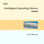
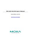
Hardware Block Diagram
1-4
2
2.
Hardware Introduction
The UC-8112 embedded computers are compact and rugged, making them suitable for industrial applications.
The LED indicators allow users to monitor performance and identify trouble spots quickly, and the multiple
ports can be used to connect a variety of devices. The UC-8112 comes with a reliable and stable hardware
platform that lets you devote the bulk of your time to application development. In this chapter, we provide
basic information about the embedded computer’s hardware and its various components.
The following topics are covered in this chapter:
Appearance
LED Indicators
Default Programmable Button Operations
Reset to Default Button
Real Time Clock
Placement Options
DIN Rail Mounting
Wall or Cabinet Mounting
UC-8112-LX-STK Manual
Hardware Introduction
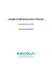
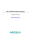
Appearance
Front View
Top & Bottom Views
Top
Bottom
2-2
UC-8112-LX-STK Manual
Hardware Introduction
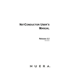
Dimensions
units: mm (in)
LED Indicators
Refer to the following table for information about each LED.
LED Name
USB
Color
Function
Green
Steady On
USB device is connected and working
normally
Off
USB device is not connected.
SD
Green
Steady On
SD Card inserted and working normally
Off
SD Card is not detected
Power
Green
Power is on and the computer is working normally.
Off
Power is off.
Green
Steady On
Blinking
Data transmitting
Yellow
Steady On
10 Mbps Ethernet link
Blinking
Data transmitting
LAN1/2 (On
RJ45
connector)
100 Mbps Ethernet link
Off
Ethernet is not connected
Wireless
Green
Number of glowing LEDs indicates signal strength
Signal
Yellow
3 (Green + Yellow + Red): Excellent
Strength
Red
2 (Yellow + Red) : Good
1 (Red) : Poor
Diagnosis
Off
Wireless module not detected
Green
These 3 LEDs can be programmed by the user
Yellow
(Refer to Chapter 3 in the Hardware Manual for details.)
Red
2-3
UC-8112-LX-STK Manual
Hardware Introduction
Default Operations for Programmable LEDs
Status of the 3 LEDs
Green LED Yellow LED
Red LED
Status Description
Off
Off
On
SD Card Error – Can’t read from or write to the SD card
Off
On
On
WAN Ethernet Error – WAN Ethernet controller malfunction
On
Off
On
LAN Ethernet Error – LAN Ethernet controller malfunction
Off
Blinking
On
IP Address Error – IP Address conflict; re-configure the UC-8110’s LAN
Off
Off
Blinking
Power-Off Warning
IP address to solve this problem
Power off may result in damage to the UC-8110 due to
•
Updating firmware
•
Saving configuration
•
Initialization process
On
On
On
RS-232 Interface Error
Blinking
Blinking
Blinking
Proceeding with Self Diagnosis
Blinking
Off
Off
Automatic Pairing (Button)
•
Press and hold the button for 2 seconds to enable automatic
pairing mode.
•
Simply click the button “Smart Connect” on the software utility
(Moxa Nexus for Windows, iOS, or Android) on any handheld
device to seamlessly access this device via the Moxa Cloud
Solution.
•
Automatic pairing mode will be disabled after X seconds. (X is
•
When automatic pairing mode is enabled, the green “Diagnosis”
•
Any successful pairing will disable the automatic pairing mode
configurable, default is 30.)
LED will keep blinking.
immediately.
Off
Blinking
Off
Automatic Pairing (QR-Code)
•
Scanning the QR-Code on the UC-8110 from the software utility on
a handheld device will enable automatic pairing mode
•
•
Refer to “Automatic Pairing (Button)”
The only exception is the Yellow “Diagnosis” LED, which will keep
blinking when automatic pairing mode is enabled.
Off
On
Off
Reset to Factory Default
Reset to Default Button
Press and hold the Reset Button continuously for at least 5 seconds to load the factory default
configuration. After the factory default configuration has been loaded, the system will reboot automatically.
The Ready LED will blink on and off for the first 5 seconds, and then maintain a steady glow once the system
has rebooted.
We recommend that you only use this function if the software is not working properly and you want to load
factory default settings. The Reset to Default functionality is not designed to hard reboot the UC-8112.
ATTENTION
Reset to Default preserves user’s data
The Reset to Default function will NOT format the user directory and erase the user’s data. Using the Reset
to default function will only load the configuration file. The rest of the user’s data stored in the Flash ROM will
remain intact.
2-4
UC-8112-LX-STK Manual
Hardware Introduction
Real Time Clock
The UC-8112’s real time clock is powered by a lithium battery. We strongly recommend that you do not replace
the lithium battery without help from a qualified Moxa support engineer. If you need to change the battery,
contact the Moxa RMA service team.
WARNING
There is a risk of explosion if the battery is replaced by an incorrect type.
Placement Options
There are two sliders on the back of the unit for DIN rail and wall mounting.
DIN Rail Mounting
Pull out the bottom slider, latch the unit onto the DIN rail, and push the slider back in.
Wall or Cabinet Mounting
Pull out both the top and bottom sliders and align the screws accordingly.
2-5
UC-8112-LX-STK Manual
Hardware Introduction
Another method for wall mounting installation is to use the optional wall mounting kit. Attach two mounting
brackets on the side panel of the computer, and fasten with screws. Install the computer on a wall or cabinet
by fastening two screws for each bracket.
NOTE
Before tightening the screws into the wall, make sure the screw head and shank size are suitable by inserting
the screw into one of the keyhole-shaped apertures of the wall mounting plates.
2-6
3
3.
Hardware Connection Description
This chapter describes how to connect the UC-8112 to a network and various devices for first time testing
purposes.
The following topics are covered in this chapter:
Wiring Requirements
Connecting the Power
Grounding the Unit
Connecting to the Console Port
Connecting to the Network
Connecting to a Serial Device
Inserting the SD and SIM Card
USB Port
Inserting a Micro SD Card
Installing the Cellular Module
Installing the Wi-Fi Module
UC-8112-LX-STK Manual
Hardware Connection Description
Wiring Requirements
In this section, we describe how to connect various devices to the embedded computer. You should heed the
following common safety precautions before proceeding with the installation of any electronic device:
•
Use separate paths to route wiring for power and devices. If power wiring and device wiring paths must
cross, make sure the wires are perpendicular at the intersection point.
NOTE
Do not run signal or communication wiring and power wiring in the same wire conduit. To avoid interference,
wires with different signal characteristics should be routed separately.
•
You can use the type of signal transmitted through a wire to determine which wires should be kept separate.
The rule of thumb is that wiring that shares similar electrical characteristics can be bundled together.
•
Keep input wiring and output wiring separate.
•
When necessary, it is strongly advised that you label wiring to all devices in the system.
ATTENTION
Safety First!
Be sure to disconnect the power cord before doing installations and/or wiring.
Electrical Current Caution!
Calculate the maximum possible current in each power wire and common wire. Observe all electrical codes
dictating the maximum current allowable for each wire size.
If the current goes above the maximum ratings, the wiring could overheat, causing serious damage to your
equipment.
Temperature Caution!
Be careful when handling the unit. When the unit is plugged in, the internal components generate heat, and
consequently the outer casing may feel hot to the touch.
Connecting the Power
The UC-8112 has a 3-pin terminal block for a 12 to 24 VDC power input.
The following figure shows how the power input interface connects to external power sources. If the power is
properly supplied, the Power LED will light up. The Ready LED will glow a solid green color when the operating
system is ready (it may take 30 to 60 seconds for the operating system to boot up).
Terminal Block
ATTENTION
The power for this product is intended to be supplied by a Listed Power Supply Unit that is rated to deliver 12
to 24 VDC at a minimum of 450 mA @ 12 VDC, and 225 mA @ 24 VDC.
3-2
UC-8112-LX-STK Manual
Hardware Connection Description
Grounding the Unit
Grounding and wire routing help limit the effects of noise due to electromagnetic interference (EMI). Run the
ground connection from the ground screw to the grounding surface prior to connecting devices.
ATTENTION
This product is intended to be mounted to a well-grounded mounting surface, such as a metal panel.
SG: The Shielded Ground (sometimes called Protected Ground) contact is the bottom contact of the 3-pin
power terminal block connector when viewed from the angle shown here. Connect the SG wire to an
appropriate grounded metal surface.
ATTENTION
A shielded power cord is required to meet FCC emission limits and also to prevent interference with nearby
radio and television reception. It is essential that only the supplied power cord be used.
You are cautioned that changes or modifications not expressly approved by the party responsible for
compliance could void your authority to operate the equipment.
Connecting to the Console Port
The UC-8112’s console port is a 4-pin pin-header RS-232 port located on the top panel of the case. It is
designed for serial console terminals, which are useful for identifying the boot up message, or for debugging
when the system cannot boot up.
Serial Console Port & Pinouts
Pin
Signal
1
TxD
2
RxD
3
NC
4
GND
Serial Console Cable
Connecting to the Network
Connect one end of the Ethernet cable to one of the UC-8112’s 10/100M Ethernet ports (8-pin RJ45) and the
other end of the cable to the Ethernet network. If the cable is properly connected, the UC-8112 will indicate a
valid connection to the Ethernet in the following ways:
3-3
UC-8112-LX-STK Manual
Hardware Connection Description
The LED indicator in the lower right corner glows a solid green color
Pin
when the cable is properly connected to a 100 Mbps Ethernet network. 1
Signal
ETx+
The LED will flash on and off when Ethernet packets are being
2
ETx-
transmitted or received.
3
ERx+
4
–
The LED indicator in the upper right corner glows a solid orange color 5
–
when the cable is properly connected to a 10 Mbps Ethernet network. 6
ERx-
The LED will flash on and off when Ethernet packets are being
7
–
transmitted or received.
8
–
Connecting to a Serial Device
Use properly wired serial cables to connect the UC-8112 to serial devices. The serial ports of the UC-8112 use
the 5-pin terminal block. The ports can be configured by software for RS-232, RS-422, or 2-wire RS-485. The
precise pin assignments are shown in the following table:
Terminal Block
RS-232/422/485 Pinouts
Pin
RS-232
RS-422
1
TXD
TXD+
RS-485
–
2
RXD
TXD-
–
3
RTS
RXD+
D+
4
CTS
RXD-
D-
5
GND
GND
GND
Inserting the SD and SIM Card
The UC-8112 comes with an SD socket for storage expansion, and a SIM card socket that can be installed with
a SIM card for cellular communication. The SD card/SIM card sockets are located on the lower part of the front
panel. To install them, remove the screw and the protection cover to access the socket, and then plug the SD
card and the SIM card into the sockets directly. Remember to push in on the SD card or SIM card first if you
want to remove them.
The SD card will be mounted at /mnt/sd.
ATTENTION
The UC-8112 does not support SD hot swap and PnP (Plug and Play) functionality. It is necessary to remove
power source first before inserting or removing the SD card.
3-4
UC-8112-LX-STK Manual
Hardware Connection Description
USB Port
The UC-8112 provides 1 USB 2.0 full speed port (OHCI), type A connector, which supports a keyboard or mouse,
as well as an external flash disk for storing large amounts of data.
Inserting a Micro SD Card
The UC-8112 comes with a micro SD card socket for storage expansion. Follow these steps:
1. Remove the screws on the side panel, and take off the cover.
2. Insert the micro SD card into the socket. Make sure you insert the card in the correct direction.
3. Replace the cover to complete the installation.
Installing the Cellular Module
The UC-8112 provides a PCIe socket for installing a cellular socket. Follow these steps:
1. Remove the screws on the side panel, and take off the cover.
2. Find the location of the PCIe socket. Insert the cellular module into the socket, and then tighten the screws
to fasten the socket.
3-5
UC-8112-LX-STK Manual
Hardware Connection Description
3. Next, you need to install the antenna cable. There are two antenna connectors on the cellular module.
Connect the cable to either connector.
4. Plug the other end of the cable into the connector on the front panel of the UC-8112. Remove the black
plastic cover first.
5. Install the connector; place the locking washer first, and then tighten the nut.
6. Connect the antenna to the connector.
3-6
UC-8112-LX-STK Manual
Hardware Connection Description
Installing the Wi-Fi Module
Follow these steps to install the Wi-Fi Module to the UC-8112-LX computer.
1. Remove the screws on the side panel, and take off the cover.
2. Find the location of the PCIe socket. Insert the cellular module into the socket, and then tighten the screws
to fasten the socket.
3. Use the two silver screws to fasten the stabilization bracket to the Wi-Fi module. Make sure you connect the
bracket in the correct direction. Insert the Wi-Fi module into the PCIe socket, and then fasten with the
bracket into place using the two black screws.
4. Next you need to install the antenna cable. There are two antenna connectors on the Wi-Fi module. Connect
the cable onto either connector.
3-7
UC-8112-LX-STK Manual
Hardware Connection Description
4. Install the other end of the cable onto the connector on the front panel of the UC-8112. Remove the black
plastic cover first.
5. Install the connector; place the locking washer first, and then tighten the nut.
6. Connect the antenna to the connector.
3-8
4
4.
Remote Configuration and Management
This chapter describes how to use the web-based tool, Webmin, to remotely configure and management the
UC-8112-LX computer. Webmin is a web-based system configuration tool that helps users to configure various
functions, such as user management, disk quota setting, services or configuration files, as well as modify and
control open source apps, such as Apache HTTP Server, PHP orMySQL.
The following topics are covered in this chapter:
Connecting to the UC-8112 via Webmin
Configuring Webmin
Viewing More Options
View Module Logs
Change Language and Theme
System Information
Webmin Action Logs
Refresh Modules
Webmin Configuration
Webmin Users
Configuring System
Bootup and Shutdown
Disk and Network Filesystems
Initial System Bootup
Running Processes
Scheduled Cron Jobs
Software Package Updates
Software Packages
System Documentation
System Log
Configuring Server
Apache Webserver
DHCP Server
Read User Mail
Configuring Others
Command Shell
File Manager
Configuring Networking
Bandwidth Monitoring
Linux Firewall
Network Configuration
Hardware
Partitions and Local Disks
System Time
Logout
UC-8112-LX-STK Manual
Remote Configuration and Management
Connecting to the UC-8112 via Webmin
Use an Ethernet cable to connect to your laptop or computer to the LAN1 port of the UC-8112 computer. Use
a browser and connect with the following address:
https://192.168.3.127:10000
When successfully connected to the UC-8112, the following figure will appear:
Provide the following information for Username and Password:
Username: root
Password: root
The main menu options will be displayed on the left, and the main information of the UC-8100 will be shown in
the middle.
Check all of the information for the UC-8112 computer, and then configure the UC-8112 using the menu
options on the left.
You may also connect the UC-8112 computer to the network, and remotely connect to the IP address of the
UC-8112 computer.
Configuring Webmin
When you click Webmin, four options will be displayed. Click the option related to the item or items you would
like to configure.
4-2
UC-8112-LX-STK Manual
Remote Configuration and Management
Change Language and Theme
You may change the language from the Personal choice drop-down list, or use the default value, Global
language, English as the Webmin UI language.
You may also change the theme of the Webmin UI from the Personal choice drop-down list.
Webmin Action Logs
When the file log function has been enabled, you may find the action log here. If you wish to search the logs in
all modules, select In any module; if you wish to search the logs in the specific module, select the module in
the drop-down list of In module. In addition, you may also search the logs by date; select from Actions on
dates option. You may also search the logs that contain a specific description; provide the description in the
Action description contains field. When finished, click Search to start searching.
4-3
UC-8112-LX-STK Manual
Remote Configuration and Management
Webmin Configuration
This option contains various configuration tools that help users to configure the UC-8112 computer.
IP Access Control
This option helps you configure the IP address control for the UC-8100 computer. You may allow or deny the
specific IP addresses. You may also decide whether or not to resolve the hostname on every request, or use the
remote IP address provided by proxy server. When finished, click Save. For other configurations, click Return
to Webmin configuration.
4-4
UC-8112-LX-STK Manual
Remote Configuration and Management
Logging
This option allows you to configure the log functions. You may decide to enable or disable logging function. Other
functions are also provided. Users may configure all settings on this page. When finished, Click Save. For other
configurations, click Return to Webmin configuration.
Proxy Servers and Downloads
This option allows users to configure the HTTP proxy and FTP proxy. Fill in the specific fields. When finished,
click Save. For other configurations, click Return to Webmin configuration.
4-5
UC-8112-LX-STK Manual
Remote Configuration and Management
User Interface
This option allows users to configure the user interface settings, such as background color, text color, and link
color, etc. When finished, click Save. For other configurations, click Return to Webmin configuration.
Webmin Modules
This option allows users to install modules on the UC-8100 by retrieving the module files from the specific
locations. When finished, click Save. For other configurations, click Return to Webmin configuration.
4-6
UC-8112-LX-STK Manual
Remote Configuration and Management
Operating System and Environment
This option allows users to display the operating system and environment detected by Webmin. When
necessary, you may update or upgrade the operating system and environment from this option. When finished,
click Save. For other configurations, click Return to Webmin configuration.
Language
This option allows users to view the language of the Webmin. You may change the language from the
drop-down list of Display in language. When finished, click Save. For other configurations, click Return to
Webmin configuration.
4-7
UC-8112-LX-STK Manual
Remote Configuration and Management
Index Page Options
This option allows users to configure the index page appearance of the Webmin. Select the options from the
following figure. When finished, click Save. For other configurations, click Return to Webmin configuration.
Upgrade Webmin
This option allows users to upgrade the Webmin version. You may upgrade from files in different locations.
When finished, click Upgrade Webmin. For other configurations, click Return to Webmin configuration.
4-8
UC-8112-LX-STK Manual
Remote Configuration and Management
Authentication
This option allows users to configure the authentication settings. You may configure all settings in this figure.
When finished, click Save. For other configurations, click Return to Webmin configuration.
Two-Factor Authentication
This option allows users to enable the addition device when logging. Select from the drop-down list in
Authentication provider. When finished, click Save. For other configurations, click Return to Webmin
configuration.
4-9
UC-8112-LX-STK Manual
Remote Configuration and Management
Reassign Modules
This option allows users to configure the category to which each module is assigned. You may reassign these
modules to different categories. When finished, click Change Categories. For other configurations, click
Return to Webmin configuration.
Edit Categories
This option allows users to edit the name of the categories shown in Webmin. You may use the default ID name
or provide a new name. When finished, click Save Categories. For other configurations, click Return to
Webmin configuration.
4-10
UC-8112-LX-STK Manual
Remote Configuration and Management
Module Titles
This option allows users to specify additional titles for the modules. Select the module from the Module
drop-down list, and then provide a new title in the New title field. When finished, click Save. For other
configurations, click Return to Webmin configuration.
Webmin Themes
This option allows users to select the Webmin themes from the drop-down list. When finished, click Change.
For other configurations, click Return to Webmin configuration.
Trusted Referrers
This option allows users to configure the trusted referrers list. When finished, click Save. For other
configurations, click Return to Webmin configuration.
4-11
UC-8112-LX-STK Manual
Remote Configuration and Management
Anonymous Module Access
This option allows users to grant the access to the specific modules for the clients that do not need to log in.
Provide the information for the specific fields. When finished, click Save. For other configurations, click Return
to Webmin configuration.
File Locking
This option allows users to lock specific files to prevent concurrent modification, which could lead to file
corruption. When finished, click Save. For other configurations, click Return to Webmin configuration.
Mobile Device Option
This option allows users to select the theme for the mobile device. When finished, click Save. For other
configurations, click Return to Webmin configuration.
4-12
UC-8112-LX-STK Manual
Remote Configuration and Management
Blocked Hosts and Users
If you have blocked hosts and users, you may view the list here. For other configurations, click Return to
Webmin configuration.
Background Status Collection
This option allows users to decide if they want to collect the status in the system background. When finished,
click Save. For other configurations, click Return to Webmin configuration.
Advanced Options
This option provides the advanced options for Webmin. Users may configure these settings with their needs.
When finished, click Save. For other configurations, click Return to Webmin configuration.
4-13
UC-8112-LX-STK Manual
Remote Configuration and Management
Debugging Log Files
This option allows users to debug log files. Users may configure the settings to debug log files. When finished,
click Save. For other configurations, click Return to Webmin configuration.
Web Server Options
This option allows users to configure the web server settings. When finished, click Save. For other
configurations, click Return to Webmin configuration.
Webmin Scheduled Functions
This option allows users to view the current scheduled jobs on the modules. You may select to delete or run
these functions. For other configurations, click Return to Webmin configuration.
4-14
UC-8112-LX-STK Manual
Remote Configuration and Management
Sending Email
This option allows users to configure the setting for sending emails, and the text for email content. When
finished, click Save. If you want to send the email immediately, click Send Email. For other configurations,
click Return to Webmin configuration.
SSL Encryption
This option allows users to configure the SSL encryption settings. When finished, click Save. For other
configurations, click Return to Webmin configuration.
4-15
UC-8112-LX-STK Manual
Remote Configuration and Management
Certificate Authority
This option allows users to configure the certificate authority. All detailed descriptions are displayed on this
page. When finished, click Save. For other configurations, click Return to Webmin configuration.
Webmin Users
This option allows users to check, delete or create a new user for Webmin. In addition, you may create new
Webmin Groups for different purposes.
4-16
UC-8112-LX-STK Manual
Remote Configuration and Management
Configuring Unix User Synchronization
If you have created a new Webmin group, you may check the users on this page.
Configuring Unix User Authentication
This option allows users to manage user authentication. Users may decide or deny access for specific Unix
users. When finished, click Save. For other configurations, click Return to Webmin configuration.
View Login Sessions
This option allows users to check the current user login status. You may also cancel access to specific users and
force them to log in again.
4-17
UC-8112-LX-STK Manual
Remote Configuration and Management
Two-Factor Authentication
If you have enabled two-factor authentication, you may check the status of the two-factor authentication on
this page.
Setup RBAC
This option allows users to set up RBAC.
Password Restrictions
This option allows users to configure the password settings. When finished, click Save. For other configurations,
click Return to Webmin configuration.
4-18
UC-8112-LX-STK Manual
Remote Configuration and Management
User and Group Database
This option allows users to configure the user and group database settings. When finished, click Save. For
other configurations, click Return to Webmin configuration.
Configuring System
When you click System, nine options will be displayed. Click an option to proceed with configuration.
4-19
UC-8112-LX-STK Manual
Remote Configuration and Management
Bootup and Shutdown
This function allows users to enable specific actions when the system boots up or shuts down.
Click a button to perform the associated function.
Disk and Network Filesystems
This option allows users to mount the system files to the UC-8100 computer. Select the file from the Type
drop-down list, and then click Add mount.
4-20
UC-8112-LX-STK Manual
Remote Configuration and Management
Initial System Bootup
This option allows users to create or delete the initial process file when the computer is booting up.
If you want to delete something, select the ID and click Delete Selected Processes at the bottom of this
page.
You may also click Create a new init process to create a new one.
4-21
UC-8112-LX-STK Manual
Remote Configuration and Management
Running Processes
This option allows users to view the current running processes.
Click Search to search for a the specific process. You can also terminate or kill a process by clicking the specific
buttons.
4-22
UC-8112-LX-STK Manual
Remote Configuration and Management
Scheduled Cron Jobs
This option allows users to view the current scheduled cron jobs, or create a new scheduled cron job.
To create a new cron job, click the Create a new scheduled cron job button, and enter the information in the
fields as required. When finished, click Create.
You may also create a new environment variable by clicking the Creating a new environment variable
button. When finished, click Create.
4-23
UC-8112-LX-STK Manual
Remote Configuration and Management
If you want to allow some users to access the cron jobs, click the Control user access to cron job button.
When finished, click Save.
Software Package Updates
This option allows users to update the software package on the UC-8100 computer. Select the package, and
then click Update Selected Packages. You may also click Refresh Available Packages to view the packages to be
updated.
You may also perform the scheduled checking options at the bottom of this page. When finished, click Save.
4-24
UC-8112-LX-STK Manual
Remote Configuration and Management
Software Packages
This option allows users to search for installed packages, or install a new package. You may also upgrade all
packages on this page.
System Documentation
This option allows users to search the system documentation. Type key words in the Search for field, and then
click Search.
4-25
UC-8112-LX-STK Manual
Remote Configuration and Management
System Log
This option allows users to view and edit the current system log, or create a new system log.
Click the system log you want to edit, and then provide the relevant information. Click Save. You may also
delete this log by clicking Delete.
Click Add a new system log, and find the log you want to add in the specific field. When finished, click Save.
4-26
UC-8112-LX-STK Manual
Remote Configuration and Management
Configuring Server
Click Sever. Three options will be displayed. Click the appropriate option to continue the configuration you
would like to take care of.
Apache Webserver
This option allows users to view or delete the current Apache Webservers. You may also create a virtual host
on this page.
Click Create virtual host. You may configure the settings of the virtual host. When finished, click Create
Now.
4-27
UC-8112-LX-STK Manual
Remote Configuration and Management
DHCP Server
This option allows users to configure the DHCP server settings. Various functions are also provided, including
Edit Client Options, Edit TSIG-keys, Manually Edit Configuration, List Active Leases.
To edit the subnet settings of the current DHCP server, click the icon and then start configuring. When finished,
click Save.
4-28
UC-8112-LX-STK Manual
Remote Configuration and Management
Read User Mail
You can read user’s email here.
To configure the email settings, click module configuration. When finished, click Save.
Configuring Others
Click Others. Two options will be displayed. Click the appropriate option to take further action.
Command Shell
This option allows users to manually execute the command shell from the system. Type the command in the
field, and then click Execute command.
File Manager
This is an additional plug-in function.
4-29
UC-8112-LX-STK Manual
Remote Configuration and Management
Configuring Networking
Click Networking. Three options will be displayed. Click the appropriate option to take further action.
Bandwidth Monitoring
This option allows users to configure the network interface and the bandwidth condition.
Select the network interface, and then click Setup Now for additional configuration. When finished, click Save.
Linux Firewall
This option allows users to configure the firewall settings. You may also reset the firewall configuration on this
page.
4-30
UC-8112-LX-STK Manual
Remote Configuration and Management
Network Configuration
Network Interfaces
This option allows users to activate, view, or apply the current network interfaces. Select the functions you wish
to use.
Routing and Gateways
This option allows users to configure the routing and gateways configurations. When finished, click Save.
Hostname and DNS Client
This option allows users to configure the hostname and DNS client configuration. When finished, click Save.
4-31
UC-8112-LX-STK Manual
Remote Configuration and Management
Host Addresses
This option allows users to add a new host address or delete the existing one.
Hardware
Click Hardware. Two options will be displayed. Click the appropriate option to take further action.
Partitions and Local Disks
This option allows users to edit the disk partitions. You may edit IDE parameters, or erase all partitions on the
existing disks.
Click the partition you want to edit, and then configure the settings. When finished, click Save.
4-32
UC-8112-LX-STK Manual
Remote Configuration and Management
System Time
This option allows users to configure system time and hardware time. When finished, click Apply or Save.
Viewing More Options
Four more options can be found in the left lower corner of the Webmin window. Click an option for details.
View Module Logs
This option allows users to view the log files.
4-33
UC-8112-LX-STK Manual
Remote Configuration and Management
You may also export the files in CSV format. Select the file and then click Export as CSV.
System Information
This item allows users to view the current system information.
Refresh Modules
This item allows users to refresh the current modules on the UC-8112 computer.
Logout
Click Logout to exit Webmin. You may log in again or close your browser to exit the system.
4-34
5
5.
Wireless Module Settings
This chapter describes how to configure the Wi-Fi and cellular modules for the UC-8112-LX computer.
The following topics are covered in this chapter:
Enabling Cellular Module
Configuring the Cellular Module
Configuring the Wi-Fi Module
Bridging the Cellular to Serial Interface
UDP Server to Serial Device
UDP Client to Serial Device
TCP Server to Serial Device
TCP Client to Serial Device
Configuring the IPSec Settings
UC-8112-LX-STK Manual
Wireless Module Settings
Enabling Cellular Module
Locate Command Shell in the Others drop-down list.
Provide the required commands in the Command Shell field.
Configuring the Cellular Module
To enable and dial up the cellular module, type the following command:
cell_mgmt start
To disable and disconnect the cellular module, type the following command:
cell_mgmt stop
To power off the cellular module, type the following command:
cell_mgmt power_off
To power on the cellular module, type the following command:
cell_mgmt power_on
To keep the UC-8112 computer constantly connecting to the network, type the following command.
keep_alive
To enable the routing function of the cellular module, type the following command.
lte_router
Note that once the routing function has been enabled, the device connecting to the LAN 2 port of the UC-8112
computer can connect to the network via the cellular module. Remember to enable the device’s DHCP function.
Configuring the Wi-Fi Module
You need to edit the Wi-Fi configuration file to enable the Wi-Fi module on the UC-8112. Connect to the
UC-8112 computer and locate the configuration file at this path: /etc/wpa_supplicant.conf.
5-2
UC-8112-LX-STK Manual
Wireless Module Settings
Configuring SSID and Password
To configure the SSID and password, edit the following content:
### Open system ###
#network={
#
ssid="Open"
#
key_mgmt=NONE
#}
###################
Configuring the WEP SSID and WEP key
To configure the WEP SSID and WEP key, edit the following content:
##### WEP #####
#network={
#
ssid="WEP-ssid"
#
bssid=XX:XX:XX:XX:XX:XX
#
key_mgmt=NONE
#
wep_key0=KEY
#}
###############
Configuring WPA/WPA2 SSID/Password/PSK
To configure the SSID and password for WPA/WPA2, edit the following content:
##### WPA/WPA2 PSK #####
#network={
#
ssid="WES_AP"
#
proto=WPA WPA2 RSN
#
key_mgmt=WPA-PSK
#
pairwise=TKIP CCMP
#
group=TKIP CCMP
#
psk="123456789"
#}
#######################
Connecting to the Wi-Fi AP
To connect to the Wi-Fi AP you have just configured, type the following command in the Command shell field:
wi-fi_router
When the UC-8100 computer has successfully connected to the Wi-Fi AP, you may connect your computer to
the LAN2 port on the UC-8100, so that your computer can connect to the network.
5-3
UC-8112-LX-STK Manual
Wireless Module Settings
Bridging the Cellular to Serial Interface
This section describes how to enable the UC-8112 to communicate with peripheral devices.
UDP Server to Serial Device
Type the following command in the Command Shell so that the signal between the DUP server and serial device
can be transmitted:
socat UDP-SENDTO:REMOTE IP:REMOTE PORT
file:/dev/ttyM0,nonblock,raw,echo=0,waitlock=/var/run/ttyM0,b115200
UDP Client to Serial Device
Type the following command in the Command Shell so that the signal between the DUP client and serial device
can be transmitted.
socat UDP-SENDTO:REMOTE IP:REMOTE PORT
file:/dev/ttyM0,nonblock,raw,echo=0,waitlock=/var/run/ttyM0,b115200
TCP Server to Serial Device
Type the following command in the Command Shell so that the signal between the TCP server and serial device
can be transmitted.
socat -v TCP-LISTEN: LISTEN PORT,reuseaddr,fork
file:/dev/ttyM0,nonblock,raw,echo=0,waitlock=/var/run/ttyM0,b115200
TCP Client to Serial Device
Type the following command in the Command Shell so that the signal between the TCP client and serial device
can be transmitted:
socat TCP:REMOTE IP:REMOTE PORT
file:/dev/ttyM0,nonblock,raw,echo=0,waitlock=/var/run/ttyM0,b115200
5-4
UC-8112-LX-STK Manual
Wireless Module Settings
Configuring the IPSec Settings
To set up the IP address of the IPSec server, edit the following file: /etc/ipsec-tools.conf
## Flush the SAD and SPD
#
flush;
spdflush;
## Some sample SPDs for use racoon
#
spdadd 10.10.10.78 10.10.10.10 any -P out ipsec
esp/transport//require;
#
spdadd 10.10.10.10 10.10.10.78 any -P in ipsec
esp/transport//require;
Note that 10.10.10.10 is the IP address of the remote host.
To configure the setup key, edit the following file: /etc/racoon/racoon.conf
log notify;
path pre_shared_key "/etc/racoon/psk.txt";
path certificate "/etc/racoon/certs";
remote anonymous {
exchange_mode main,aggressive;
proposal {
encryption_algorithm aes_256;
hash_algorithm sha256;
authentication_method pre_shared_key;
dh_group modp1024;
}
generate_policy off;
}
sainfo anonymous{
pfs_group 2;
encryption_algorithm aes_256;
authentication_algorithm hmac_sha256;
compression_algorithm deflate;
}
To configure the pre-shared key, edit the following file: /etc/racoon/psk.txt.
–
10.10.10.10 1234567890
–
/etc/init.d/setkey restart
/etc/init.d/racoon restart
Note: Authentication Mode
–
Pre-shared key
–
X.509
In this example, 10.10.10.10 is the IP address of the host, while 1234567890 is the pre-shared key.
To start the IPSec configuration, run the following commands:
/etc/init.d/setkey restart
/etc/init.d/racoon restart
5-5
UC-8112-LX-STK Manual
Wireless Module Settings
Take the following steps to enable the IPSec function when the system starts up:
1.
2. Locate the Bootup and Shutdown option in Webmin.
3. Click Create a new bootup and shutdown action.
4. Enter the following commands in the Bootup commands field:
/etc/init.d/setkey restart
/etc/init.d/racoon restart
5. When finished, click Create.
5-6
6
6.
Data Acquisition
This chapter describes how to use the UC-8112 computer to acquire data from an ioLogik E1242 RTU controller.
The following topics are covered in this chapter:
Acquiring Data
UC-8112-LX-STK Manual
Data Acquisition
Acquiring Data
The UC-8112-LX Start Kit comes with an ioLogik E1242 RTU controller. To acquire data from the controller, use
the following commands in the Command Shell field.
To read the value from Digital Input 0:
Em2240 –d 192.168.31.66 –i 0
To read the value from Analog Input 0:
Em2240 –d 192.168.31.66 –i 1
To set Digital Input to high level:
Em2240 –d 192.168.31.66 –o 1 –s 1
6-2
A
A.
Regulatory Approval Statements
This device complies with part 15 of the FCC Rules. Operation is subject to the following
two conditions: (1) This device may not cause harmful interference, and (2) this device
must accept any interference received, including interference that may cause undesired
operation.
Class A: FCC Warning! This equipment has been tested and found to comply with the limits for a Class A digital
device, pursuant to part 15 of the FCC Rules. These limits are designed to provide reasonable protection
against harmful interference when the equipment is operated in a commercial environment. This equipment
generates, uses, and can radiate radio frequency energy and, if not installed and used in accordance with the
instruction manual, may cause harmful interference to radio communications. Operation of this equipment in
a residential area is likely to cause harmful interference in which case the users will be required to correct the
interference at their own expense.
European Community
WARNING
This is a class A product. In a domestic environment this product may cause radio interference in which case
the user may be required to take adequate measures.