1
ALLEN-BRADLEY
Attended Workstations
(Catalog Nos. 2708-DH5B2L & -DH5B4L)
(Series B)
User Manual
Disclaimer
Important User Information
Solid state equipment has operational characteristics differing from those of
electromechanical equipment. “Application Considerations for Solid State
Controls” (Publication SGI-1.1) describes some important differences
between solid state equipment and hard–wired electromechanical devices.
Because of this difference, and also because of the wide variety of uses for
solid state equipment, all persons responsible for applying this equipment
must satisfy themselves that each intended application of this equipment is
acceptable.
In no event will the Allen-Bradley Company be responsible or liable for
indirect or consequential damages resulting from the use or application of
this equipment.
The examples and diagrams in this manual are included solely for illustrative
purposes. Because of the many variables and requirements associated with
any particular installation, the Allen-Bradley Company cannot assume
responsibility or liability for actual use based on the examples and diagrams.
No patent liability is assumed by Allen-Bradley Company with respect to use
of information, circuits, equipment, or software described in this manual.
Reproduction of the contents of this manual, in whole or in part, without
written permission of the Allen-Bradley Company is prohibited.
Table of Contents
Attended Workstations
User Manual
Introduction
Chapter Objectives . . . . . . . . . . . . . . . . . . . . . . . . . . . . . . . . . . . . . . . . .
Catalog Numbers . . . . . . . . . . . . . . . . . . . . . . . . . . . . . . . . . . . . . . . . . .
Accessory Items . . . . . . . . . . . . . . . . . . . . . . . . . . . . . . . . . . . . . . . . . . .
Related Publications . . . . . . . . . . . . . . . . . . . . . . . . . . . . . . . . . . . . . . .
Safety Information . . . . . . . . . . . . . . . . . . . . . . . . . . . . . . . . . . . . . . . . .
1–1
1–1
1–1
1–2
1–2
Installing a Network
Chapter Objectives . . . . . . . . . . . . . . . . . . . . . . . . . . . . . . . . . . . . . . . . .
Power Requirements . . . . . . . . . . . . . . . . . . . . . . . . . . . . . . . . . . . . . . .
Simple Network . . . . . . . . . . . . . . . . . . . . . . . . . . . . . . . . . . . . . . . . . . .
The RS-485 Network Bus . . . . . . . . . . . . . . . . . . . . . . . . . . . . . . . .
The Network Connector (Catalog No. 2708-NNC) . . . . . . . . . . . . .
Cabling a Network Using the Network Connector . . . . . . . . . . . . .
Cable Wire . . . . . . . . . . . . . . . . . . . . . . . . . . . . . . . . . . . . . . . .
Preparing the Wire . . . . . . . . . . . . . . . . . . . . . . . . . . . . . . . . . .
Installing the Connector . . . . . . . . . . . . . . . . . . . . . . . . . . . . . .
Master Connection . . . . . . . . . . . . . . . . . . . . . . . . . . . . . . . . . .
NON-MASTER Connection . . . . . . . . . . . . . . . . . . . . . . . . . . .
Step By Step Installation . . . . . . . . . . . . . . . . . . . . . . . . . . . . . . . . . . . .
The Terminator Switch . . . . . . . . . . . . . . . . . . . . . . . . . . . . . . . . . . .
Communication Cables . . . . . . . . . . . . . . . . . . . . . . . . . . . . . . .
Testing the Network for Data Transmission . . . . . . . . . . . . . . . . . . . . .
Communication to the Host Computer . . . . . . . . . . . . . . . . . . . . . . . . .
Description of Large or Complex Network . . . . . . . . . . . . . . . . . . . . . .
Complex Network . . . . . . . . . . . . . . . . . . . . . . . . . . . . . . . . . . . . . . . . .
Alternate Communication Links . . . . . . . . . . . . . . . . . . . . . . . . . . .
Networks Over Telecommunications Lines . . . . . . . . . . . . . . . . . . .
2–1
2–2
2–2
2–2
2–3
2–4
2–4
2–4
2–5
2–5
2–6
2–7
2–9
2–9
2–10
2–11
2–13
2–13
2–14
2–15
Barcode Connection
Chapter Objectives . . . . . . . . . . . . . . . . . . . . . . . . . . . . . . . . . . . . . . . . .
Connection . . . . . . . . . . . . . . . . . . . . . . . . . . . . . . . . . . . . . . . . . . . . . . .
3–1
3–1
Status Displays
Introduction . . . . . . . . . . . . . . . . . . . . . . . . . . . . . . . . . . . . . . . . . . . . . .
Summary Status Display (Status Display 0) . . . . . . . . . . . . . . . . . . . . .
Network Status (Status Display 1) . . . . . . . . . . . . . . . . . . . . . . . . . . . . .
Reserved Status (Status Display 2) . . . . . . . . . . . . . . . . . . . . . . . . . . . .
Time Status (Status Display 3) . . . . . . . . . . . . . . . . . . . . . . . . . . . . . . .
System Reset Status (Status Display 4) . . . . . . . . . . . . . . . . . . . . . . . . .
A – Error Codes . . . . . . . . . . . . . . . . . . . . . . . . . . . . . . . . . . . . . . . . . . .
Network Queue Status (Status Display 5) . . . . . . . . . . . . . . . . . . . . . . .
Workstation Memory Status (Status Display 6) . . . . . . . . . . . . . . . . . .
4–1
4–2
4–4
4–5
4–5
4–5
4–6
4–6
4–8
i
Table of Contents
Attended Workstations
User Manual
Configuration Menus
ii
Program Load Status (Status Display 7) . . . . . . . . . . . . . . . . . . . . . . . .
Program Run Status (Status Display 8) . . . . . . . . . . . . . . . . . . . . . . . . .
Application Status (Status Display 9) . . . . . . . . . . . . . . . . . . . . . . . . . .
4–9
4–10
4–11
Introduction . . . . . . . . . . . . . . . . . . . . . . . . . . . . . . . . . . . . . . . . . . . . . .
Using Menus via Workstation Keypad . . . . . . . . . . . . . . . . . . . . . . . . .
Sub-Menus . . . . . . . . . . . . . . . . . . . . . . . . . . . . . . . . . . . . . . . . . . . . . . .
Exiting Network Menu . . . . . . . . . . . . . . . . . . . . . . . . . . . . . . . . . . .
Using Menus from
the Comm Port . . . . . . . . . . . . . . . . . . . . . . . . . . . . . . . . . . . . . . . . .
Menu 1: Network Menu Paramters . . . . . . . . . . . . . . . . . . . . . . . . . . . .
Workstation . . . . . . . . . . . . . . . . . . . . . . . . . . . . . . . . . . . . . . . .
Workstation Type . . . . . . . . . . . . . . . . . . . . . . . . . . . . . . . . . . .
Menu 2: Comm Port Menu Parameters . . . . . . . . . . . . . . . . . . . . . . . . .
Comm Port Mode . . . . . . . . . . . . . . . . . . . . . . . . . . . . . . . . . . .
Comm Baud Rate . . . . . . . . . . . . . . . . . . . . . . . . . . . . . . . . . . .
Comm Data Bits . . . . . . . . . . . . . . . . . . . . . . . . . . . . . . . . . . . .
Comm Parity . . . . . . . . . . . . . . . . . . . . . . . . . . . . . . . . . . . . . . .
Menu 3: System Menu Parameters . . . . . . . . . . . . . . . . . . . . . . . . . . . .
Menu 4: Bar Code Menu Parameters . . . . . . . . . . . . . . . . . . . . . . . . . .
Menu 5: Read Only Menu . . . . . . . . . . . . . . . . . . . . . . . . . . . . . . . . . . .
Menu 6: Diagnostics Menu Parameters . . . . . . . . . . . . . . . . . . . . . . . . .
1–Keypad/Laser Test . . . . . . . . . . . . . . . . . . . . . . . . . . . . . . . . . . . . . . .
2–Display Test . . . . . . . . . . . . . . . . . . . . . . . . . . . . . . . . . . . . . . . . .
3–Destructive RAM Test . . . . . . . . . . . . . . . . . . . . . . . . . . . . . . . . .
4–Continuous RAM Test . . . . . . . . . . . . . . . . . . . . . . . . . . . . . . . . .
5–Comm Transmit Test . . . . . . . . . . . . . . . . . . . . . . . . . . . . . .
6–Comm Receive Test . . . . . . . . . . . . . . . . . . . . . . . . . . . . . . . . . . . . . .
7–Comm Loop Test . . . . . . . . . . . . . . . . . . . . . . . . . . . . . . . . . . . . .
8–Aux Comm Transmit Test . . . . . . . . . . . . . . . . . . . . . . . . . . . . . .
9–Aux Comm Receive Test . . . . . . . . . . . . . . . . . . . . . . . . . . . . . . .
A–Aux Comm Loopback Test . . . . . . . . . . . . . . . . . . . . . . . . . . . . . . . .
B–RS485 Block Receive . . . . . . . . . . . . . . . . . . . . . . . . . . . . . . . . . . . .
C–RS485 Block Transmit . . . . . . . . . . . . . . . . . . . . . . . . . . . . . . . . . . .
D–RS232 Block Receive . . . . . . . . . . . . . . . . . . . . . . . . . . . . . . . . . . . .
E–RS232 Block Transmit . . . . . . . . . . . . . . . . . . . . . . . . . . . . . . . . . . .
F–Lamp Test . . . . . . . . . . . . . . . . . . . . . . . . . . . . . . . . . . . . . . . . . . . . .
G–Reset Powerup . . . . . . . . . . . . . . . . . . . . . . . . . . . . . . . . . . . . . . . . .
H–Reset Unit to Factory Defaults . . . . . . . . . . . . . . . . . . . . . . . . . . . . .
5–1
5–1
5–2
5–2
5–3
5–4
5–4
5–4
5–5
5–5
5–6
5–6
5–6
5–8
5–8
5–10
5–10
5–11
5–12
5–12
5–13
5–14
5–15
5–15
5–16
5–17
5–18
5–19
5–19
5–20
5–21
5–22
5–22
5–22
Table of Contents
Attended Workstations
User Manual
Operating Procedures
Chapter Objectives . . . . . . . . . . . . . . . . . . . . . . . . . . . . . . . . . . . . . . . . .
Verifying Proper Network Operation . . . . . . . . . . . . . . . . . . . . . . . . . .
Removing a Master . . . . . . . . . . . . . . . . . . . . . . . . . . . . . . . . . . . . . . . .
Instituting a New Workstation as Master . . . . . . . . . . . . . . . . . . . . . . . .
Removing a Workstation from the Network . . . . . . . . . . . . . . . . . . . . .
Adding a Workstation to the Network . . . . . . . . . . . . . . . . . . . . . . . . . .
Network Problems . . . . . . . . . . . . . . . . . . . . . . . . . . . . . . . . . . . . . . . . .
Workstation Status . . . . . . . . . . . . . . . . . . . . . . . . . . . . . . . . . . . . . . . . .
6–1
6–2
6–3
6–4
6–4
6–5
6–5
6–6
Network Design
Networks of 32 Workstations or Less . . . . . . . . . . . . . . . . . . . . . . . . . .
Network Installation of More than 32 Workstations . . . . . . . . . . . . . . .
Fault-Tolerant Networks . . . . . . . . . . . . . . . . . . . . . . . . . . . . . . . . . . . .
Extending Networks Over Phone Lines . . . . . . . . . . . . . . . . . . . . . . . .
7–1
7–1
7–3
7–4
Host Communications
Network Status Records . . . . . . . . . . . . . . . . . . . . . . . . . . . . . . . . . . . .
Using Retry Counts for Network Diagnosis . . . . . . . . . . . . . . . . . . . . .
Responses to Network Directives . . . . . . . . . . . . . . . . . . . . . . . . . . . . .
Network Directives . . . . . . . . . . . . . . . . . . . . . . . . . . . . . . . . . . . . . . . .
< D – Show Unit Display . . . . . . . . . . . . . . . . . . . . . . . . . . . . .
< E – Show Last Error Message . . . . . . . . . . . . . . . . . . . . . . . .
< R – Show Last Reset Message . . . . . . . . . . . . . . . . . . . . . . .
< S – Show Unit Serial Number . . . . . . . . . . . . . . . . . . . . . . . .
< T – Show Workstation Date & Time . . . . . . . . . . . . . . . . . . .
< V – Show Firmware Version . . . . . . . . . . . . . . . . . . . . . . . . .
> > A – Abort Currently Running A-B VBASIC Program . . .
> > G – Restart an Aborted BASIC Program . . . . . . . . . . . . . .
> A – Abort Test . . . . . . . . . . . . . . . . . . . . . . . . . . . . . . . . . . . .
> C – Send Text Out Comm Port . . . . . . . . . . . . . . . . . . . . . . .
> c – Send Text Out Aux Comm Port . . . . . . . . . . . . . . . . . . . .
> D – Display Text on Front Panel . . . . . . . . . . . . . . . . . . . . . .
> E – Erase the Menu Password . . . . . . . . . . . . . . . . . . . . . . . .
> F – Reset to Factory Defaults . . . . . . . . . . . . . . . . . . . . . . . .
> N – Initialize Network . . . . . . . . . . . . . . . . . . . . . . . . . . . . . .
> R – Reboot Unit . . . . . . . . . . . . . . . . . . . . . . . . . . . . . . . . . . .
> T – Set Time . . . . . . . . . . . . . . . . . . . . . . . . . . . . . . . . . . . . .
> Z – Zero Reset Error . . . . . . . . . . . . . . . . . . . . . . . . . . . . . . .
8–1
8–3
8–3
8–4
8–5
8–5
8–5
8–6
8–6
8–6
8–7
8–7
8–7
8–7
8–7
8–7
8–8
8–8
8–8
8–8
8–9
8–9
What is BASIC
Introduction . . . . . . . . . . . . . . . . . . . . . . . . . . . . . . . . . . . . . . . . . . . . . .
What is Visual BASIC ? . . . . . . . . . . . . . . . . . . . . . . . . . . . . . . . . . . . .
What is A-B VBASIC? . . . . . . . . . . . . . . . . . . . . . . . . . . . . . . . . . . . . .
9–1
9–1
9–2
iii
Table of Contents
Attended Workstations
User Manual
Developing and Running
An A-B BASIC Program
Step #1 – Planning . . . . . . . . . . . . . . . . . . . . . . . . . . . . . . . . . . . . . . . . .
The A-B VBASIC Development Procedure . . . . . . . . . . . . . . . . . . . . .
Step #2 – Coding with the Workstation Application Generator Software
10–1
Step #3 (Alternate) – Coding with Visual BASIC Editor . . . . . . . . . . .
Step #4 – Simulation Using Application Library . . . . . . . . . . . . . . . . .
Step #5 – Compiling the A-B VBASIC Program . . . . . . . . . . . . . . . . .
Step #6 – Downloading . . . . . . . . . . . . . . . . . . . . . . . . . . . . . . . . . . . . .
Loading and Auto-Starting an A-B VBASIC Program . . . . . . . . . . . . .
Start-up Condition of an A-B VBASIC Program . . . . . . . . . . . . . . . . .
LCD: . . . . . . . . . . . . . . . . . . . . . . . . . . . . . . . . . . . . . . . . . . . . .
Random numbers: . . . . . . . . . . . . . . . . . . . . . . . . . . . . . . . . . . .
RAM files: . . . . . . . . . . . . . . . . . . . . . . . . . . . . . . . . . . . . . . . .
Variables: . . . . . . . . . . . . . . . . . . . . . . . . . . . . . . . . . . . . . . . . .
Host device: . . . . . . . . . . . . . . . . . . . . . . . . . . . . . . . . . . . . . . .
Termination of an A-B VBASIC Program . . . . . . . . . . . . . . . . . . . . . .
A-B VBASIC Run-Time Errors . . . . . . . . . . . . . . . . . . . . . . . . . . . . . .
Format of a BASIC Error Message . . . . . . . . . . . . . . . . . . . . . . . . . . . .
Power Failure . . . . . . . . . . . . . . . . . . . . . . . . . . . . . . . . . . . . . . . . . . . . .
10–1
10–1
10–2
10–2
10–3
10–3
10–3
10–3
10–3
10–3
10–3
10–4
10–5
10–5
10–6
The A-B VBASIC
Cross-Compiler
Overview . . . . . . . . . . . . . . . . . . . . . . . . . . . . . . . . . . . . . . . . . . . . . . . .
Invoking the Compiler . . . . . . . . . . . . . . . . . . . . . . . . . . . . . . . . . . . . . .
LXB param 1 (,param2) (,param3) (,param4) . . . . . . . . . . . . .
LXB . . . . . . . . . . . . . . . . . . . . . . . . . . . . . . . . . . . . . . . . . . . . .
LXB Prog1 . . . . . . . . . . . . . . . . . . . . . . . . . . . . . . . . . . . . . . . .
LXB Prog1,Prog1,Prog1 . . . . . . . . . . . . . . . . . . . . . . . . . . . . .
LXB Prog1,Download,PRN . . . . . . . . . . . . . . . . . . . . . . . . . . .
LXB Prog1,Startnow,Prog1,Wait . . . . . . . . . . . . . . . . . . . . . . .
A – Source File Specification . . . . . . . . . . . . . . . . . . . . . . . . . . . . . . . .
B – Downloaded Executable File . . . . . . . . . . . . . . . . . . . . . . . . . . . . .
C – Listing File . . . . . . . . . . . . . . . . . . . . . . . . . . . . . . . . . . . . . . . . . . .
D – Secondary Download File . . . . . . . . . . . . . . . . . . . . . . . . . . . . . . . .
11–1
11–2
11–2
11–3
11–3
11–3
11–3
11–3
11–3
11–4
11–4
11–4
Special Devices in
A-B VBASIC
Introduction . . . . . . . . . . . . . . . . . . . . . . . . . . . . . . . . . . . . . . . . . . . . . .
Device: LCD Display . . . . . . . . . . . . . . . . . . . . . . . . . . . . . . . . . . . . . .
Device: Keypad . . . . . . . . . . . . . . . . . . . . . . . . . . . . . . . . . . . . . . . . . . .
Device: Barcode Scanners . . . . . . . . . . . . . . . . . . . . . . . . . . . . . . . . . . .
When reading barcodes: . . . . . . . . . . . . . . . . . . . . . . . . . . . . . .
Device: Host Computer . . . . . . . . . . . . . . . . . . . . . . . . . . . . . . . . . . . . .
12–1
12–2
12–3
12–4
12–4
12–6
iv
10–1
10–1
....
Table of Contents
Attended Workstations
User Manual
A-B VBASIC Application
Library
General restrictions and warnings: . . . . . . . . . . . . . . . . . . . . . .
Details of Specific Statements and Functions . . . . . . . . . . . . . . . . . . . .
OPEN “HOST” . . . . . . . . . . . . . . . . . . . . . . . . . . . . . . . . . . . . .
CLOSE “HOST” . . . . . . . . . . . . . . . . . . . . . . . . . . . . . . . . . . . .
WRITE # . . . . . . . . . . . . . . . . . . . . . . . . . . . . . . . . . . . . . . . . . .
PUT to HOST . . . . . . . . . . . . . . . . . . . . . . . . . . . . . . . . . . . . . .
PUT to NET . . . . . . . . . . . . . . . . . . . . . . . . . . . . . . . . . . . . . . .
PUT to QUE . . . . . . . . . . . . . . . . . . . . . . . . . . . . . . . . . . . . . . .
PRINT # . . . . . . . . . . . . . . . . . . . . . . . . . . . . . . . . . . . . . . . . . .
LINE INPUT # for HOST and NET
GET # for HOST and NET (OPEN with RANDOM) . . . .
LINE INPUT # for QUE
GET # for QUE (OPEN with RANDOM enforced) . . . . .
EOF for HOST and NET . . . . . . . . . . . . . . . . . . . . . . . . . . . . .
LOC for HOST and NET . . . . . . . . . . . . . . . . . . . . . . . . . . . . .
LOF for HOST . . . . . . . . . . . . . . . . . . . . . . . . . . . . . . . . . . . . .
LOF for NET . . . . . . . . . . . . . . . . . . . . . . . . . . . . . . . . . . . . . .
IOCTL$ (intrinsic function) for HOST and NET . . . . . . . . . .
IOCTL (statement) for HOST . . . . . . . . . . . . . . . . . . . . . . . . .
Devices: Communication Ports, Primary and Auxiliary . . . . . . . . . . . .
A – Output to a Communication Port . . . . . . . . . . . . . . . . . . . . . . . . . .
B – Input from a Communication Port . . . . . . . . . . . . . . . . . . . . . . . . .
C – Modem Control Lines . . . . . . . . . . . . . . . . . . . . . . . . . . . . . . . . . . .
Device: RAM Files . . . . . . . . . . . . . . . . . . . . . . . . . . . . . . . . . . . . . . . .
Description: . . . . . . . . . . . . . . . . . . . . . . . . . . . . . . . . . . . . . . .
File Memory Management . . . . . . . . . . . . . . . . . . . . . . . . . . . .
Device: Beeper . . . . . . . . . . . . . . . . . . . . . . . . . . . . . . . . . . . . . . . . . . . .
Device: Front Panel LED’s . . . . . . . . . . . . . . . . . . . . . . . . . . . . . . . . . .
Device: The #9 User Status Display . . . . . . . . . . . . . . . . . . . . . . . . . . .
Description: . . . . . . . . . . . . . . . . . . . . . . . . . . . . . . . . . . . . . . .
Device: The Egg Timer . . . . . . . . . . . . . . . . . . . . . . . . . . . . . . . . . . . . .
Description: . . . . . . . . . . . . . . . . . . . . . . . . . . . . . . . . . . . . . . .
12–7
12–8
12–8
12–9
12–9
12–9
12–9
12–9
12–9
12–10
12–10
12–10
12–10
12–10
12–11
12–11
12–11
12–12
12–12
12–13
12–13
12–13
12–14
12–14
12–14
12–15
12–15
12–16
12–16
Introduction . . . . . . . . . . . . . . . . . . . . . . . . . . . . . . . . . . . . . . . . . . . . . .
Using the Library . . . . . . . . . . . . . . . . . . . . . . . . . . . . . . . . . . . . . . . . . .
Writing Programs . . . . . . . . . . . . . . . . . . . . . . . . . . . . . . . . . . . . . . . . . .
Using the ENVPC Simulator . . . . . . . . . . . . . . . . . . . . . . . . . . . . . . . . .
A – Predefined Constants . . . . . . . . . . . . . . . . . . . . . . . . . . . . . . . . .
B – Global Variables . . . . . . . . . . . . . . . . . . . . . . . . . . . . . . . . . . . . .
C – BASIC Language Development Kit Limitations . . . . . . . . . . . .
D – PC Simulation Constants and Variables . . . . . . . . . . . . . . . . . .
Display and Keyboard . . . . . . . . . . . . . . . . . . . . . . . . . . . . . . .
Network I/O . . . . . . . . . . . . . . . . . . . . . . . . . . . . . . . . . . . . . . .
13–1
13–2
13–3
13–4
13–5
13–6
13–7
13–7
13–8
13–8
12–10
v
Table of Contents
Attended Workstations
User Manual
COM and AUX . . . . . . . . . . . . . . . . . . . . . . . . . . . . . . . . . . . . .
Status Display . . . . . . . . . . . . . . . . . . . . . . . . . . . . . . . . . . . . . .
Printing Reports and Forms . . . . . . . . . . . . . . . . . . . . . . . . . . .
13–8
13–9
13–9
Electrical – 2708-NP1 . . . . . . . . . . . . . . . . . . . . . . . . . . . . . . . . . . . . . .
Electrical – 2708-NP2 . . . . . . . . . . . . . . . . . . . . . . . . . . . . . . . . . . . . . .
Mechanical – 2708-DH5B2L and -DH5B4L . . . . . . . . . . . . . . . . . . . .
Communication Ports . . . . . . . . . . . . . . . . . . . . . . . . . . . . . . . . . . . . . .
........................................................
A–1
A–1
A–1
A–1
B–1
Technical Description
........................................................
C–1
Workstation Communication
Pin-Out Diagrams
........................................................
D–1
Network (RS-485) Cable Length . . . . . . . . . . . . . . . . . . . . . . . . . . . . . .
RS-232 (MASTER or HOST) Cable Length . . . . . . . . . . . . . . . . . . . . .
E–1
E–1
Site Parameter List
........................................................
F–1
Network Pin-Out Diagrams
for DB9 Connector
........................................................
G–1
Error Messages and Prompts
........................................................
H–1
Time Display Formats
........................................................
I–1
Programming Conventions . . . . . . . . . . . . . . . . . . . . . . . . . . . . . . . . . .
Programming Tips . . . . . . . . . . . . . . . . . . . . . . . . . . . . . . . . . . . . . . . . .
J–1
J–2
2708-DH5B2L and -DH5B4L
Workstation Specifications
Menu Trigger Keys
Distance Limitations
VBASIC Language
Development Kit
Programming Conventions
and Tips
vi
Table of Contents
Attended Workstations
User Manual
A-B VBASIC and
Visual BASIC Tips
Misspellings . . . . . . . . . . . . . . . . . . . . . . . . . . . . . . . . . . . . . . . . . . . . . .
Strings in TYPEs . . . . . . . . . . . . . . . . . . . . . . . . . . . . . . . . . . . . . . . . . .
Variables Beginning with “FN” . . . . . . . . . . . . . . . . . . . . . . . . . . . . . . .
Accidental Omission of %, &, ! # OR $ . . . . . . . . . . . . . . . . . . . . . . . .
Use of Colons as Statement Separators . . . . . . . . . . . . . . . . . . . . . . . . .
CONSTant Declarations . . . . . . . . . . . . . . . . . . . . . . . . . . . . . . . . . . . .
PRINT “text”; : <statement> . . . . . . . . . . . . . . . . . . . . . . . . . . . . . . . . .
K–1
K–1
K–1
K–1
K–1
K–2
K–2
Differences Between
A-B VBASIC and
Visual BASIC
General Restrictions . . . . . . . . . . . . . . . . . . . . . . . . . . . . . . . . . . . . . . . .
Supported A-B VBASIC Keywords . . . . . . . . . . . . . . . . . . . . . . . . . . .
ABS(numeric–expression) . . . . . . . . . . . . . . . . . . . . . . . . . . . . . . . .
ASC(string–expression) . . . . . . . . . . . . . . . . . . . . . . . . . . . . . . . . . .
BEEP . . . . . . . . . . . . . . . . . . . . . . . . . . . . . . . . . . . . . . . . . . . . . . . .
CDBL(numeric–expression) . . . . . . . . . . . . . . . . . . . . . . . . . . . . . .
CHAIN filespec . . . . . . . . . . . . . . . . . . . . . . . . . . . . . . . . . . . . . . . .
CHR$(code) . . . . . . . . . . . . . . . . . . . . . . . . . . . . . . . . . . . . . . . . . . .
CINT(numeric–expression) . . . . . . . . . . . . . . . . . . . . . . . . . . . . . . .
CLNG(numeric–expression) . . . . . . . . . . . . . . . . . . . . . . . . . . . . . .
CLOSE [ [#]filenumber[,[#]filenumber]...] . . . . . . . . . . . . . . . . . . .
CLS [{ 0 | 1 | 2 }] . . . . . . . . . . . . . . . . . . . . . . . . . . . . . . . . . . . . . . .
CONST constname=expression . . . . . . . . . . . . . . . . . . . . . . . . . . . .
CSNG(numeric–expression) . . . . . . . . . . . . . . . . . . . . . . . . . . . . . .
CSRLIN . . . . . . . . . . . . . . . . . . . . . . . . . . . . . . . . . . . . . . . . . . . . . .
CVI, CVS, CVL, (CVD) . . . . . . . . . . . . . . . . . . . . . . . . . . . . . . . . .
DATE$ . . . . . . . . . . . . . . . . . . . . . . . . . . . . . . . . . . . . . . . . . . . . . . .
DATE$ = ”yymmddw” . . . . . . . . . . . . . . . . . . . . . . . . . . . . . . . . . . .
DECLARE {FUNCTION | SUB} name(parameters) . . . . . . . . . . .
DEFINT letterrange[,letterrange]... . . . . . . . . . . . . . . . . . . . . . . . . .
DEFSNG letterrange[,letterrange]... . . . . . . . . . . . . . . . . . . . . . . . . .
(DEFDBL letterrange[,letterrange]...) No longer supported . . . . . .
DEFLNG letterrange[,letterrange]... . . . . . . . . . . . . . . . . . . . . . . . .
DEFSTR letterrange[,letterrange]... . . . . . . . . . . . . . . . . . . . . . . . . .
DIM [SHARED] variable[(subscripts)][AS type]... . . . . . . . . . . . . .
DO...LOOP [{WHILE/UNTIL} booleanexpression] . . . . . . . . . . .
END [{FUNCTION/IF/SELECT/SUB/TYPE}] . . . . . . . . . . . . . . .
EOF(filenumber) . . . . . . . . . . . . . . . . . . . . . . . . . . . . . . . . . . . . . . .
FIX(x) . . . . . . . . . . . . . . . . . . . . . . . . . . . . . . . . . . . . . . . . . . . . . . . .
FOR counter = start TO end [STEP increment]
...
L–1
L–1
L–2
L–2
L–2
L–2
L–2
L–3
L–3
L–3
L–3
L–3
L–4
L–4
L–4
L–4
L–4
L–4
L–5
L–5
L–5
L–5
L–5
L–5
L–6
L–6
L–6
L–6
L–7
NEXT [counter] . . . . . . . . . . . . . . . . . . . . . . . . . . . . . . . . . . . . .
L–7
vii
Table of Contents
Attended Workstations
User Manual
FRE(numeric expression) . . . . . . . . . . . . . . . . . . . . . . . . . . . . . . . . .
FREEFILE . . . . . . . . . . . . . . . . . . . . . . . . . . . . . . . . . . . . . . . . . . . .
FUNCTION name[(parameterlist)][STATIC] . . . . . . . . . . . . . . . . .
GET [#]filenumber[,[recordnumber][,variable]] . . . . . . . . . . . . . . .
GOSUB {linelabel | linenumber}....RETURN . . . . . . . . . . . . . . . . .
GOTO {linelabel/linenumber} . . . . . . . . . . . . . . . . . . . . . . . . . . . . .
HEX$(expression) . . . . . . . . . . . . . . . . . . . . . . . . . . . . . . . . . . . . . .
IF...THEN...ELSE . . . . . . . . . . . . . . . . . . . . . . . . . . . . . . . . . . . . . .
INKEY$ . . . . . . . . . . . . . . . . . . . . . . . . . . . . . . . . . . . . . . . . . . . . . .
INPUT$(bytecount[,[#]filenumber]) . . . . . . . . . . . . . . . . . . . . . . . .
INSTR([start,]stringexpression1,stringexpression2) . . . . . . . . . . . .
INT(numeric–expression) . . . . . . . . . . . . . . . . . . . . . . . . . . . . . . . .
IOCTL$([#]filenumber) . . . . . . . . . . . . . . . . . . . . . . . . . . . . . . . . . .
IOCTL[#]filenumber,string . . . . . . . . . . . . . . . . . . . . . . . . . . . . . . .
KILL “filespec” . . . . . . . . . . . . . . . . . . . . . . . . . . . . . . . . . . . . . . . .
LBOUND(array[,dimension]) . . . . . . . . . . . . . . . . . . . . . . . . . . . . .
LCASE$(stringexpression) . . . . . . . . . . . . . . . . . . . . . . . . . . . . . . .
LEFT$(stringexpression, n) . . . . . . . . . . . . . . . . . . . . . . . . . . . . . . .
LEN(stringexpression) . . . . . . . . . . . . . . . . . . . . . . . . . . . . . . . . . . .
LEN(variable) . . . . . . . . . . . . . . . . . . . . . . . . . . . . . . . . . . . . . . . . . .
LINE INPUT[;][“promptstring”;]stringvariable . . . . . . . . . . . . . . .
LINE INPUT #filenumber,stringvariable . . . . . . . . . . . . . . . . . . . . .
LOC(filenumber) . . . . . . . . . . . . . . . . . . . . . . . . . . . . . . . . . . . . . . .
LOCATE[row][,[column][,[cursor]]] . . . . . . . . . . . . . . . . . . . . . . . .
LOF(filenumber) . . . . . . . . . . . . . . . . . . . . . . . . . . . . . . . . . . . . . . .
LTRIM$(stringexpression) . . . . . . . . . . . . . . . . . . . . . . . . . . . . . . . .
MID$(stringexpression, start[, length]) . . . . . . . . . . . . . . . . . . . . . .
MKD$, MKI$, MKL$, MKS$ . . . . . . . . . . . . . . . . . . . . . . . . . . . . .
OCT$(numeric–expression) . . . . . . . . . . . . . . . . . . . . . . . . . . . . . . .
ON expression GOSUB {line–number–list/line–label–list} . . . . . .
ON expression GOTO {line–number–list/line–label–list} . . . . . . .
OPEN file [FOR mode1][ACCESS] AS[#]filenum [LEN=reclen] .
POS(0) . . . . . . . . . . . . . . . . . . . . . . . . . . . . . . . . . . . . . . . . . . . . . . .
PRINT [expressionlist][{,|;}] . . . . . . . . . . . . . . . . . . . . . . . . . . . . . .
PRINT #filenumber,[USING stringexpression;] expressionlist[{,|;}]
PRINT USING formatstring; expressionlist[{,|;}] . . . . . . . . . . . . . .
PUT [#]filenumber[,[recordnumber][,variable]] . . . . . . . . . . . . . . .
RANDOMIZE expression . . . . . . . . . . . . . . . . . . . . . . . . . . . . . . . .
REM remark
‘ remark . . . . . . . . . . . . . . . . . . . . . . . . . . . . . . . . . . . . . . . . . . .
RETURN . . . . . . . . . . . . . . . . . . . . . . . . . . . . . . . . . . . . . . . . . . . . .
RIGHT$(stringexpression, n) . . . . . . . . . . . . . . . . . . . . . . . . . . . . . .
RND . . . . . . . . . . . . . . . . . . . . . . . . . . . . . . . . . . . . . . . . . . . . . . . . .
RTRIM$(stringexpression) . . . . . . . . . . . . . . . . . . . . . . . . . . . . . . . .
viii
L–8
L–8
L–8
L–8
L–9
L–9
L–9
L–9
L–10
L–10
L–10
L–10
L–10
L–11
L–11
L–11
L–11
L–11
L–12
L–12
L–12
L–12
L–12
L–13
L–13
L–13
L–13
L–13
L–14
L–14
L–14
L–14
L–14
L–14
L–15
L–15
L–15
L–15
L–16
L–16
L–16
L–16
L–16
Table of Contents
Attended Workstations
User Manual
Application Library
Subroutines
A-B VBASIC Limits
SEEK(filenumber) . . . . . . . . . . . . . . . . . . . . . . . . . . . . . . . . . . . . . .
SEEK [#]filenumber,position . . . . . . . . . . . . . . . . . . . . . . . . . . . . . .
SELECT CASE text_expression . . . . . . . . . . . . . . . . . . . . . . . . . . .
SGN(numeric–expression) . . . . . . . . . . . . . . . . . . . . . . . . . . . . . . . .
SHARED variable [AS type] [,variable [AS type]]... . . . . . . . . . . .
SLEEP seconds . . . . . . . . . . . . . . . . . . . . . . . . . . . . . . . . . . . . . . . . .
SOUND frequency,duration . . . . . . . . . . . . . . . . . . . . . . . . . . . . . . .
SPACE$(n) . . . . . . . . . . . . . . . . . . . . . . . . . . . . . . . . . . . . . . . . . . . .
STATIC variablelist . . . . . . . . . . . . . . . . . . . . . . . . . . . . . . . . . . . . .
STOP . . . . . . . . . . . . . . . . . . . . . . . . . . . . . . . . . . . . . . . . . . . . . . . .
STR$(numeric–expression) . . . . . . . . . . . . . . . . . . . . . . . . . . . . . . .
STRING$(m,n) . . . . . . . . . . . . . . . . . . . . . . . . . . . . . . . . . . . . . . . . .
STRING$(m,stringexpression) . . . . . . . . . . . . . . . . . . . . . . . . . . . . .
SUB globalname[(parameterlist)][STATIC]
...
...
L–16
L–16
L–17
L–17
L–17
L–17
L–18
L–18
L–18
L–18
L–18
L–19
L–19
END SUB . . . . . . . . . . . . . . . . . . . . . . . . . . . . . . . . . . . . . . . . . .
SWAP vari1,vari2 . . . . . . . . . . . . . . . . . . . . . . . . . . . . . . . . . . . . . . .
SYSTEM . . . . . . . . . . . . . . . . . . . . . . . . . . . . . . . . . . . . . . . . . . . . .
TIME$ . . . . . . . . . . . . . . . . . . . . . . . . . . . . . . . . . . . . . . . . . . . . . . .
TIME$ = stringexpression . . . . . . . . . . . . . . . . . . . . . . . . . . . . . . . .
TIMER . . . . . . . . . . . . . . . . . . . . . . . . . . . . . . . . . . . . . . . . . . . . . . .
TYPE usertype . . . . . . . . . . . . . . . . . . . . . . . . . . . . . . . . . . . . . . . . .
END TYPE . . . . . . . . . . . . . . . . . . . . . . . . . . . . . . . . . . . . . . . . . . . .
UBOUND(array[,dimension]) . . . . . . . . . . . . . . . . . . . . . . . . . . . . .
UCASE$(stringexpression) . . . . . . . . . . . . . . . . . . . . . . . . . . . . . . .
VAL(stringexpression) . . . . . . . . . . . . . . . . . . . . . . . . . . . . . . . . . . .
WHILE condition . . . . . . . . . . . . . . . . . . . . . . . . . . . . . . . . . . . . . . .
WEND . . . . . . . . . . . . . . . . . . . . . . . . . . . . . . . . . . . . . . . . . . . . . . .
WRITE #filenumber [,expressionlist] . . . . . . . . . . . . . . . . . . . . . . .
L–19
L–19
L–19
L–20
L–20
L–20
L–20
L–20
L–21
L–21
L–21
L–21
L–21
L–21
In ENV.BAS and ENVPC.BAS . . . . . . . . . . . . . . . . . . . . . . . . . . . . . . .
In READ.BAS . . . . . . . . . . . . . . . . . . . . . . . . . . . . . . . . . . . . . . . . . . . .
In MENU.BAS . . . . . . . . . . . . . . . . . . . . . . . . . . . . . . . . . . . . . . . . . . .
In TRIG.BAS . . . . . . . . . . . . . . . . . . . . . . . . . . . . . . . . . . . . . . . . . . . . .
In HYP.BAS . . . . . . . . . . . . . . . . . . . . . . . . . . . . . . . . . . . . . . . . . . . . . .
........................................................
M–1
M–1
M–1
M–2
M–2
N–1
ix
Chapter
A–B
1
Introduction
Chapter Objectives
Allen-Bradley workstations are designed to be rugged and very reliable when
installed using the correct voltage and network cabling. An inexpensive
network connector (Catalog No. 2708-NNC) has been designed in order to
simplify the network installation. Although the workstations may be securely
installed without this connector, it is highly recommended that this connector
be used. The time saved and the ease of installation will be significant.
Chapters 2 through 4 describe network installation, host communication, and
the connection of barcode scanners.
Installation of a network includes cabling (both power and network) and
configuration of the workstations. In some instances, it may be necessary to
consult Chapters 5 through 8 for detailed information on the proper ways to
configure the workstations.
Catalog Numbers
The catalog numbers covered by this manual include Attended Workstations
2708-DH5B2L and 2708-DH5B4L.
Accessory Items
Accessory items for the 2708-DH5B2L and -DH5B4L workstations are listed
below:
Item
DH5 Power Supply, U.S.
DH5 Power Supply, Europe
Catalog No.
2708-NP1
2708-NP2
DH5 Network Connector
2708-NNC
Application Generator Software
2708-NAG
Network Manager Software
2708-NNM
Basic Language Development Kit
Software
Hand-Held Scanner
Bar Code Wand
Bar Code Wand
Bar Code Wand
Slot Scanner
2708-NBD
2755-G3, -G6
2755-W1
2755-W2
2755-W5
2755-B1, -B2
Description
Accepts 120V AC input power.
Accepts 240V AC input power.
Communications port connector that may be wired for point-to-point or
multidrop applications.
Menu-driven development software package for custom application
programming. Includes Catalog Nos. 2708–NNM and –NBD.
Terminal emulator software utilities package that allows the workstation to
be configured for a variety of network configurations.
Contains a set of source files that can be used to reduce program
development time.
Visible laser diode, moving beam, hand-held scanner for bar codes.
Visible red light source (high density bar codes).
Visible red light source (low density bar codes).
Infrared light source (high density bar codes).
Slot scanner for bar codes.
1–1
Chapter 1
Introduction
Related Publications
Publication No.
The following table lists the publications that are available:
Title
Purpose of Publication
2708-801
Application Generator User’s Manual
Describes how to use Application Generator Software to create
custom application programs.
2708-802
Network Manager User’s Manual
Describes how to use the Network Manager Software to
configure the workstation for a variety of network configurations.
2708-803
Basic Language Kit User’s Manual
2708-2.3
A-B VBASIC vs. Visual BASICt
Describes how to use the Basic Language Kit source files to
reduce program development time.
Describes the differences between standard Visual BASICt
and the Allen-Bradley VBASIC modified for use with the
2708-DH5B_L workstation.
Safety Information
Throughout this manual we use notes to make you aware of safety
considerations.
!
ATTENTION: Identifies information about practices or
circumstances that can lead to personal injury or death, property
damage, or economic loss.
Important: Identifies information that is especially important for successful
application and understanding of the product.
1–2
Chapter
A–B
2
Installing a Network
Chapter Objectives
The physical network is based on a twisted pair cabling technique that
follows the Electronic Industrial Association (EIA) RS-485 standard. This
standard specifies the electrical characteristics of the balanced voltage digital
interface circuit. This electrical standard is similar to the more familiar
RS-422 standard. The RS-485 communication drivers are capable of
withstanding greater voltage surges and tolerating more installation errors
than standard RS-422 communications.
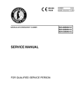
The RS-485 network cabling system used by the workstations is a
daisy-chain (or multidrop) architecture. Each workstation is directly
connected to its neighbor. An example of this multidrop architecture is
shown in Figure 2.1.
Figure 2.1
RS-485 Multidrop Architecture
Network Connector
(Catalog No. 2708-NNC)
RS-485
RS-232 or RS-422
From Host
Master
Normal
To Other
Workstations
Normal
Normal
Although the workstations in the network may be physically identical, the
network role of an individual workstation may be different from its neighbor.
The seven possible network configurations are:
Normal
Master
Alternate
Concentrator
Submaster
Alt Submaster
Gateway
Standard Workstation
Communicates with host computer via COM1
Backup for the Master
Connects Submaster to backbone network
Connects tributary to Concentrator
Backup for Submaster
Master/Concentrator
These configurations are described in Chapters 5 through 8 along with
workstation set-up instructions. It is necessary to understand the
configuration set-up to be able to wire the network properly.
The network check out may be entirely accomplished by using the diagnostic
tests resident in the workstations.
2–1
Chapter 2
Installing a Network
Simple Network
Power Requirements
Each workstation must be powered with 28V of AC power. This power is
supplied by the power supply (Catalog No. 2708-NP1, -NP2) which is a
sealed AC adaptor that is plugged into a wall outlet. The power output cable
is plugged into the power connector as shown in Figure 2. A full diagram of
all the connectors is shown in Figure 2.2.
Figure 2.2
Back Plate of the Workstation
ALLEN-BRADLEY
COM2
MADE IN USA
COM1
BARCODE
485 NET
PWR
In a normal installation, each individual workstation is powered by its own
power supply.
The RS-485 Network Bus
It is highly important to recognize that the network should be wired to appear
as a continuous cable or bus and should not be spliced in a manner that
allows the cable to make a 3-way junction. Figure 2.3 shows the right way to
wire a network.
Figure 2.3
Correct Network Connection
Network
Connector
Workstation
2–2
Workstation
Workstation
Chapter 2
Installing a Network
Simple Network (cont’d)
Figure 2.3 shows the correct method of wiring a network. This figure shows
the cable coming into the Network Connector (Catalog No. 2708-NNC) and
making connection with the cable coming out of the connector. If the
workstations are removed from their respective network connectors, it is easy
to determine that a continuous cable or bus has been created.
The network is a signal transmission line and cannot be treated the same as a
power voltage line. The transmission line operates at considerably higher
frequencies and therefore must be properly wired and terminated (resistance
loaded). If this network transmission line is not installed properly, as shown
in Figure 2.3, then voltage standing wave reflections (VSWR) and various
other propagation phenomenon may occur.
This could cause workstations to not come on-line, drop off and on-line, or
have multiple communication retrys in order to make a signal connection.
!
ATTENTION: It must be emphasized that the network cable be
installed as a transmission line and not as a power voltage line.
As discussed in this section, a simple network consists of a single cable to
connect up to 32 workstations. This is called a “backbone” network and is
diagramed on Figure 2.4.
Figure 2.4
Simple Network Configuration
Host
W
M
M—W—W—W—W—W—W—W—W—W
Workstation
Master
Indicates RS-232
Indicates RS-485 backbone
No more than 32 workstations can be connected to the same network cable.
If more than 32 workstations are required, refer to the Complex Networks
section.
The Network Connector (Catalog No. 2708-NNC)
The Network Connector is made up of three elements. These are (1) the
plastic shroud or hood, (2) the DB-9 connector, and (3) the four screw
terminal block. The terminal block is wired to the back of the DB-9
connector. The black terminal wire is connected to pin 5 of the DB-9
connector and is the network (–) side of the RS-485 network. The red
terminal wire is connected to pin 4 of the DB-9 connector and is the network
(+) side of the RS-485 network. The blue terminal wire is the workstation’s
terminal’s chassis ground, and is connected to pin 8. The last terminal slot is
open and is not connected to the DB-9 connector.
2–3
Chapter 2
Installing a Network
Simple Network (cont’d)
Figure 2.5
Network Connector (Catalog No. 2708-NNC)
Cabling a Network Using the Network Connector
Tools Needed — You will need a 3/32” flatblade screwdriver, and a pair of
wire strippers/cutter.
Cable Wire
The recommended cable is a Belden 8723. This cable has 2 pair of
conductors (4 wires) and a common drain wire. Although only one pair of
conductors is necessary for the network, it is desirable to have a back-up or
secondary pair in the event the primary pair has an open wire or some
unforseen malfunction occurs in the primary pair.
The primary cable pair consists of a Red and Black conductor which match
the color of the Network Connector leads. This primary pair will be used in
describing the cable connection.
Preparing the Wire
Check that the cable is cut off evenly. (There should be no wire hanging
beyond the cable insulation.) Remove about 3/4” of the insulation from the
end of the cable. Strip about 1/4” of insulation from the end of each wire.
Figure 2.6
Cable Connecting Length
1/4”
3/4”
2–4
Chapter 2
Installing a Network
Simple Network (cont’d)
Installing the Connector
There are two types of connections using the Network Connector. These are
a Master connection and a Non-Master connection. These connections are
shown on Figure 2.7. The physical network connector is shown on Figure
2.4. An examination of both figures shows that there are four open sockets in
which to place three wires; the network plus (+), the network (–), and the
shield wires. In the Network Connector, the three wires connecting the
terminal block to the pins in the DB-9 connector are color coded. This is
consistent with all Network Connectors. It is advised the cable be
color-coded to match the Network Connector to avoid confusion.
Master Connection
The network (–) wire is placed in the connector socket for pin 5 of the
network connector. The network (+) wire is placed in the connector socket
for pin 4 of the network connector. The shield or drain wire is placed in the
connector socket for pin 8 and is the ground connection.
The shield wire is placed in the blue connector socket ONLY in a MASTER
or SUB-MASTER connection. This will effectively ground the network
cable at the MASTER only, and eliminate ground loop current problems.
Figure 2.7
Schematic of the RS-485 Network Using the Network Connector
Network Connector (Catalog No. 2708-NNC)
Master Workstation
Normal Workstation
Normal Workstation
To Other
Workstations
Shield or
Drain
Wire
Net (+)
Net (–)
2–5
Chapter 2
Installing a Network
Simple Network (cont’d)
NON-MASTER Connection
The following connections are NON-MASTER connections:
Normal
Concentrator
Alternate
Alternate Master
Alternate Sub-Master
All Non-Master workstations, with the exception of the last workstation in
the network, will have a cable going into and a cable coming out of the
network connector. This will cause two wires to be installed in each
connector socket. This is shown on Figure 2.8.
Figure 2.8
Two Wires in a Connector Socket
Twist the network (–) wires (black) together and place them in the black
connector socket and tighten the screw. Next, twist the network (+) wires
(red) together and place them in the red connector socket and tighten the
screw. The only cable leads left should be the drain or shield wires. Twist
these together and place them in the empty socket that has NO wire going to
the DB-9 connector. Tighten the screw and then examine all connections to
make sure they are secure and that no wires are touching any adjacent
connections to cause short circuits.
If the cable was cut and stripped according to instructions, it should be
straightforward to put the shroud on the network connector and complete the
assembly. When possible, it is advantageous to use the cable restraint device
in the connector to avoid pulling connections loose or breaking the wire.
Remember, cabling problems are the number one cause of problems in a
network.
2–6
Chapter 2
Installing a Network
Step By Step Installation
It is recommended that at least a simple volt/ohm meter along with assorted
screwdrivers be acquired for installation.
Figure 2.9
The Completed Network Connector
Making a good cable installation is one of the keys to having a properly
working network. Cable installation must always alternate between
installation and inspection. The inspector’s job is to play devil’s advocate at
each phase. By inspecting in phases, you avoid having to do the entire job
over again when problems are found too late.
We recommend the following sequence:
1. Obtain tools, select connectors and cable type. Get a sample of the cable
so you can identify the colors.
2. Draw a MAP of where each workstation is to be placed in the building or
area. Trace a general path that the cable will follow in the physical
building. Make multiple copies of this diagram. One good way to do the
map is to get blueprints of the building and draw in the cables and
workstations. Make sure that you note the WORKSTATION NUMBER
which will be in each location, as well as the location of the Host
computer.
3. Make color keyed cable drawings showing which color wires go to the
pins of the connectors. We recommend you make multiple copies of this
drawing, and store one copy with the installation map.
4. Run the cable through the building. Always leave a few extra feet at each
workstation location so that there is room with which to work.
2–7
Chapter 2
Installing a Network
Step By Step Installation
(cont’d)
5. Inspect the locations where the cable has been run, using a different
person than the installer. Make sure that the cable:
a. Is not run parallel to AC cables (BUILDING POWER) for more
than a few feet at any time. This will avoid induction of AC onto
your low voltage data network. Whenever the network cable must
cross AC power lines, they should cross perpendicular to each
other.
b. Is not allowed to rest on top of fluorescent lamps in the ceiling. The
ballasts from these lamps are worse than AC power lines.
c. Is never spliced in a manner that allows the cable to make a 3-way
junction. Network cables must be a bus. Only the Master
workstation and the last workstation can have a single network
cable going to them; all others will have two cables.
d. Is not located next to or run over large motors, building
transformers, or very large current areas, such as radiology labs.
e. Is not located where it is easily broken or shifted around.
Note: Make sure that the workstations are not next to building
transformers, or large electric motors. Induced voltage spikes can affect
the operation of the network.
6. Inspect visually every connector. It is recommended that a person, other
than the one who connected the wires, inspects the following:
a. Correct COLORS of wire have been connected.
b. Be sure that ALL of the strands of the conductor are properly
inserted into the connector. It is very easy to nick the wire when
stripping it. This results in the strands breaking.
c. Flex the wire at the connector a few times (this is not the time to
prove your strength, THEY CAN BE BROKEN) to see if the wire
has been badly nicked. It will break if this has occurred.
7. Inspect the pins for proper color in the proper hole.
8. Check continuity of the network cable by:
a. Temporarily short pins 4 and 5 of the MASTER workstation’s
network connector together. You can do this with a clip lead, or use
a female 9 pin solder type connector with pins 4 and 5 soldered
together. (You can get solder type connectors at local electrical
retailers.)
b. Set the voltmeter to the 100 OHM scale (or the nearest available
value).
2–8
Chapter 2
Installing a Network
Step By Step Installation
(cont’d)
c. At the next workstation location, place the meter on pins 4 and 5.
You should have almost no resistance. A good rule of thumb is 1
ohm for every 25 feet of network cable. If there is 400 feet of cable
to the Master, then there should be no more than 16 ohms of
resistance.
d. Try each workstation in turn, checking to see that the resistance
does not change drastically. If the resistance is high, you may have
a poorly crimped pin, or a partial break in the cable itself. If the
resistance is infinite (completely open), then there is a break, or a
broken conductor.
e. By going from one station to the next, you can isolate what
segment of the cable has a problem.
f. When the entire cable has been checked, remove the jumper from
the Master’s connector.
9. Install the hoods on the connectors. Attach the connectors to the
workstations.
The Terminator Switch
After the network is installed, it is usually necessary to cancel out signal
reflections inherent in any cable layout. To do this, flip on the terminator
switch underneath the MASTER and SUBMASTER WORKSTATIONS
ONLY. The terminator switch is on the bottom of the workstation. The ON
position is toward the top of the workstation.
Figure 2.10
Terminator Switch
Note: The terminator switch should be OFF on all workstations except the
MASTER and SUBMASTER. If other terminator switches are on,
indeterminate network conditions will occur.
Communication Cables
The cables used to communicate from the Host computer to the Master or
from a Concentrator to a Sub-Master workstation use either RS-232 or
RS-422 signal standards. The connector pin-out diagrams for all of the
possible workstation configurations are shown in Appendix D.
2–9
Chapter 2
Installing a Network
Testing the Network for
Data Transmission
1. At the LAST workstation in the network, place the workstations into the
menu setup mode (see Appendix B).
a. Press the left arrow key (<) until the Diagnostic menu statement
appears in the display.
b. Press the ENTER key and then depress the left arrow key (<) until
RS-485 – BLK-Rx is shown on the display.
c. Press the ENTER key and the following should appear:
Rx = 00000
000
ERRS = 00
If the counters are not zero, press EXIT, then press ENTER, and they
should be set to zero.
d. Repeat steps a, b, and c for all workstations, except the Master
workstation.
2. At the Master workstation enter the Diagnostic menu and press the left
arrow key (<) until RS-485 – BLK-Tx is shown on the display.
a. Press ENTER and the display should show the following,
momentarily:
Tx = 00000
000
ERRS = 00
After the counters appear, the Tx counter will begin incrementing to
represent the number of blocks being transmitted over the network to all
workstations.
b. An observation of the display of the workstations placed in receive
will show the Rx counter changing accordingly as the transmitted
network blocks are received.
c. After a reasonable testing interval, press the EXIT key on the
Master workstation, thus suspending the network block test.
d. Examine each workstation to see that the Rx block count is the
same. It should be the same at all workstations (It is possible to be
off by one or two counts.) Also, inspect to see that ERRS count is
zero or less than three. Either a missing block count or high error
count indicates a bad network connection or a faulty workstation.
Exchanging the workstation will determine which is the case.
e. For additional confidence, perform step 1 at the Master workstation
location and step 2 at the last location. Step 1 may be repeated at all
other workstations. The changing of block transmission locations
verifies communications in the opposite direction.
f. Press EXIT three times on each workstation.
3. Always use retaining screws for all DB-9 connectors. Connect the RS-232
(or RS-422) cable to the host computer.
2–10
Chapter 2
Installing a Network
Communication to the
Host Computer
Connect the WORKSTATION COM1 Port to the Host computer using a
cable wired according to the pin-out diagrams shown in Appendix D. To
communicate to the Host computer, it is necessary to be able to make your
computer send and receive ASCII characters in an asynchronous
communication manner. If a personal computer is used, programs such as
PROCOMMR, and KERMIT are ideal for this purpose. Most
ASYNCHRONOUS TERMINAL EMULATION PROGRAMS will work.
The communication set-up parameters must be the same for both the
computer and the workstation terminal. Please see Appendix B, Menu
Trigger Keys, for the procedure to enter the workstation menu mode.
If the program is resident in the workstation, press the menu trigger keys
(Enter and Right Arrow simultaneously), disconnect power, then reconnect
power while holding down the Enter and Right Arrow keys simultanenously
to enter the workstation menu mode.
1. In the menu mode
1—Network
Menu
will appear.
Press ENTER; “Terminal Number” will appear.
Press 1, then ENTER; “Terminal Type” will appear.
Press < – until the terminal type changes to “Master”,
then press ENTER, then press EXIT.
2. Press the < –, until “2-Comm Port Menu” appears. Press ENTER;
“Comm Port Mode” will appear.
Press < – until the mode changes to “XON/XOFF”.①
Press ENTER; and “Comm Baud Rate” will appear.
3. Press < – until the baud rate is the SAME AS THE BAUD RATE
SELECTED ON THE HOST COMPUTER. 9600 and 1200 are the most
common baud rates.② In some cases NO character will show up if the
baud rate is improperly set.
Press ENTER; “Comm Data Bits” will appear.
4. Press < – until the Data Bits are the same as the Host computer. This is
normally 7.
Press ENTER “Comm Parity” will appear.
① For testing the cable connections, use XON/XOFF. If you are using a data collection program such as Network
Manager Software (Catalog No. 2708-NNM), you may have to change this to “POLLED” before using such
programs.
② If the baud rate is incorrectly set, when your computer sends characters to the workstation, unpredictable
characters will show up on the display when you are in “COMM RECEIVE TEST” mode. In some cases NO
character will show up if the baud rate is improperly set.
2–11
Chapter 2
Installing a Network
5. Press < – until the parity is the SAME AS THE PARITY SETTING ON
THE HOST COMPUTER. A selection of “EVEN” is commonly used.③
Press ENTER; “Comm Stop Bits” will appear.
6. Press < – until “One” appears.④
Press ENTER; “Comm CRLF” will appear.
7. Press < – until “ENABLED” appears.⑤
Press ENTER; “Comm Echo” will appear.
8. Press < – until “ENABLED” appears.⑥
Press EXIT; “1-Network Menu” will appear.
9. Press OUT; “Diagnostics” will appear.
Press ENTER; Press < – until “Comm Rx Test” appears.
Press ENTER;
10. The following should appear on the two line display:
DTR: ON
CD: ON
Pressing the number 1 and 2 will turn DTR ON and OFF.⑦
11. Start the communication program on the Host computer. If the program is
an asynchronous terminal emulator program, then characters that are
typed on the computer are sent directly over the communication line.
These characters should appear on the top line of the workstation
display.⑧
12. Press EXIT; “Comm Rx Test” will appear.
Press OUT; “Comm Tx Test” will appear.
Press ENTER; The top line will be blank and the second line will show:
DTR: ON
CD: ON
The Host computer should be receiving a continuous transmission of
③ If the parity is set incorrectly, the workstation will still RECEIVE characters properly. Your Host computer may not
receive correctly, if at all.
④ If the baud rate is incorrectly set, when your computer sends characters to the workstation, unpredictable
characters will show up on the display when you are in “COMM RECEIVE TEST” mode. In some cases NO
character will show up if the baud rate is improperly set.
⑤ If you find that your computer is receiving double spaced lines from the workstation, then set CRLF to
DISABLED. Also disable when using Network Manager Software (Catalog No. 2708-NNM) or similar software.
⑥ If you find that when you are using your workstation program, you see two characters for each one you type
(such as DDIISSPPLLAAYY//HHEELLOO//) then set Com Echo to DISABLED. Note that when using a data
collection program (such as Network Manager Software (Catalog No. 2708-NNM) you will also DISABLE this
option.
⑦ Your computer may be unwilling to transmit characters unless these RS-232 lines are in the proper state. If you
are having trouble communicating, check your cable diagram against the specifications for your computer’s
RS-232 port. Additionially, the workstation requires CD to be high (or on) for communications.
⑧ Random characters on your computer or the workstation display indicate the baud rate is wrong. If about half of
the characters are wrong or missing, the parity is set incorrectly. If nothing at all happens, the cable is wrong or
something is broken.
2–12
Chapter 2
Installing a Network
“The quick brown fox jumped over the lazy dog”⑨ type of messages.
Communications can receive at rates that are faster than any terminal
emulation program due to the use of POLLED mode as the COMM
PORT MODE.
13. Press EXIT, three times
14. The AUX port (labeled COM2 on the back of the workstation) can be set
up and checked out in the same manner as the primary COM1 port. The
AUX port, however, is strictly a data transfer port operating with
XON/XOFF flow control. It has transmit, receive, and signal ground
lines. There are no modem control lines on this port.
The installation of the workstation in a simple network is now complete.
Complex Network
Description of Large or Complex Network
Installing a large or complex network of workstations involves connecting
together several smaller networks.
The network which connects all of the smaller or sub-networks together is
called the “backbone” network. Each sub-network is referred to as a
“tributary” network. Up to 31 tributary networks may be attached to the
backbone to form a very large network. Each tributary, in turn, may contain
up to 32 workstations. A maximum of 1024 workstations may be connected
in this fashion. Once the layout of such a network has been determined,
cabling proceeds in the same manner as cabling for a single or backbone
network. Both tributary and backbone networks are wired as previously
described.
The workstation which is attached to the Host is configured as the “Master”.
Each workstation on the backbone network that connects to a tributary
network is configured as “Concentrator”. The workstation on the tributary
which attaches to the Concentrator is configured as the “Sub-Master”.
⑨ After a few seconds or minutes of receiving these messages, your computer starts displaying wrong characters or
only parts of messages, then your computer (or the communications program) is unable to accept records at the
rate they are being sent by the workstation. Try a lower baud rate on your Host and the workstation until you can
receive successfully as quickly as the data is sent. Note that some programs such as Network Manager Software
(Catalog No. 2708-NNM) can receive at rates that are faster than any terminal emulation program due to the use
of POLLED mode as the COMM PORT MODE.
2–13
Chapter 2
Installing a Network
Figure 2.11
Large Network Configuration
Host
Key: W
S
C
M
W
|
W
W
|
|
W
W
|
|
S
S
|
|
M—W—C—W—C—W—C—W—W—C—C—W
|
|
|
S
S
S
|
|
|
W
W
W
|
|
|
W
W
W
|
|
W
W
|
W
Workstation
Submaster
Concentrator
Master
Indicates RS-232 or RS-422 connection
Indicates RS-485 backbone
Indicates a tributary
All of the workstations, including Masters, Concentrators and Submasters,
are standard workstations which have been configured for their individual
roles in the network. A configuration parameter is changed to allow any
workstation to adopt a new role in the network. Each workstation is capable
of operating in both a data collection and a data communications mode.
A workstation which is being used as a Master, Concentrator, or
Submaster can perform data collection functions even while serving in
the communication network.
Alternate Communication Links
When installing large networks, you may consider redundant communication
links in order to protect against Host or Master workstation failures. This
involves establishing certain workstations as “Alternate Sub-Masters”.
Configuring a large network with Alternate Masters will allow the alternate
workstation to take over communication operations if the designated Master
becomes inoperable or is removed from the network. An Alternate Host
provides full redundancy for collection in the event of a Host failure.
2–14
Chapter 2
Installing a Network
Figure 2.12
Large Network Configuration with Alternate Masters
Host 1
Host 2
Key: W
S
M
C
A
AS
W
|
W
W
|
|
W
AS
|
|
S
S
|
|
M—A—C—C—C—W—C—C—W—C—C—C
|
|
|
S
S
S
|
|
|
AS
W
AS
|
|
|
W
W
W
|
W
Workstation
Submaster
Master
Concentrator
Alternate Master
Alternate Submaster
Indicates RS-232 or RS-422 connection
Indicates RS-485 backbone
Indicates a tributary
An Alternate Submaster will allow the communication operations to continue
through a secondary Concentrator if the primary Concentrator becomes
inoperable or is removed from the network.
Networks Over Telecommunications Lines
It is possible to configure a workstation network which spans multiple
buildings, outposts, or sub-stations located at remote sites. Switched or
leased telephone lines can be used with asynchronous modems to provide
communication links for such a network.
Asynchronous short-haul modems may be used to extend the normal RS-232
communication distance from 100 feet to as much as several miles. To use
modems for communications between a Concentrator and Submaster the
workstations MUST have an RS-232 communication port (Workstation
Catalog No. 2708-DH5B2L). A modem cable must be correctly connected to
TXD, RXD, RTS, CTS, DSR, DTR, and GROUND signals (see Appendix
D). The COMM BAUD RATE parameter must be changed to the same baud
rate as the modem.
2–15
Chapter 2
Installing a Network
As soon as the modems establish communication between themselves, the
remote system will be ready for use.
Extension of a network across telephone lines consists of placing a modem
on one side of the line to connect with the Concentrator, and placing another
modem on the other side to connect with the Submaster.
Figure 2.13
Extending Network Across Common Carrier
Backbone
Network
W
|
M
|
W
|
W
|
C
|
W
|
W
Key: W
S
C
M
Tributary
Network
W
|
W
|
W
|
S
|
W
HOST
modem
modem
Telco
Workstation
Submaster
Concentrator
Master
Indicates RS-232 connect
Indicates telephone line
Indicates RS-485 backbone
Figure 2.14
Use of the Gateway Option
Backbone
Network
Tributary
Network
W
|
W
|
G
|
W
|
W
W
|
S
|
W
Key: W
S
C
M
G
2–16
modem
modem
Telco
Workstation
Submaster
Concentrator
Master
Gateway
Indicates RS-232 connect
Indicates telephone line
Indicates RS-485 backbone
Chapter
A–B
3
Barcode Connection
Chapter Objectives
The barcode connector on the back of the workstation is a 9 pin DB-9
connector for the bar code scanner.
Connection
The pin-out for the BARCODE connector on the back of the workstation is
shown on Figure 3.1.
Figure 3.1
BARCODE Connector
5
4
9
3
8
2
7
Pin Number
1 ...............
2 ...............
3 ...............
4 ...............
5 ...............
6 ...............
7 ...............
8 ...............
9 ...............
1
6
Function
Start of Scan
Data
LED light
NOT CONNECTED
Trigger
Laser synchronization
GROUND
GROUND
Power (+5V)
Allen-Bradley offers the following barcode scanners for use with the
workstation:
— Catalog Number 2755-G3 or -G6 Hand-Held Scanner
— Catalog Number 2755-W1, -W2, or -W5 Wand
— Catalog Number 2755-B1 or -B2 Slot Scanner
3–1
Chapter
A–B
4
Status Displays
Introduction
The status display provides visible and easily available information
concerning the state of the 2708-DH5B2L or -DH5B4L Attended
Workstation. The workstation reports its operational status through ten
informational displays on the front panel LCD Display. The status displays
are automatically shown when the workstation is powered up unless a
BASIC program is running. Each of the status displays is assigned a number
from 0 to 9. To see status display 1, press the “1” key. When any number is
entered, the workstation will present the status display associated with that
number. The ten displays are:
1.
2.
3.
4.
5.
6.
7.
8.
9.
0.
Network Status.
Reserved Status.
Time Status.
System Reset Status.
Network Que Status.
Workstation Memory Status.
Program Load Status.
Program Run Status.
Application Status.
Summary Status.
On the workstation’s 2 x 40 display, two separate status displays will be
shown.
Figure 4.1
Example Status Display
N . . . . . . NN .
01–01
01234556789
MASTR
<0 2>
NETWORK 2
4–1
Chapter 4
Status Displays
Introduction (cont’d)
With the display, the workstation can show two status displays at the same
time. In Figure 4.1, the summary status display is on the left hand side along
with the reserved status on the right hand side. The ‘< 0’(in Figure 4.1) is
associated with the summary status (left hand side), and signifies that the
summary status is status display number zero. The ‘2>’ tells us that the right
hand display is status display number 2.
On the display, as the user selects a new status display, the new status screen
will be displayed on the left hand side, and the display on the right hand side
will be replaced by the one from the left hand side.
Invoking Status Display – Status displays are visible under these
circumstances:
1. After power-up for 15 seconds.
2. When the workstation has a non-zero terminal number, but is without an
A-B VBASIC program.
3. When the A-B VBASIC program terminates.
4. When manually invoked during a power up. This method will present the
status display for 15 seconds after the last keystroke. The A-B VBASIC
program, if loaded, will resume execution after this 15 second status
display.
Summary Status Display
(Status Display 0)
The Status Display 0 summarizes the status of the other nine status displays.
The numbers 0-9 on the lower line represent the ten status displays. The
information above each number refers to the number under it, i.e. the ’.’ over
the 3 refers to the status display 3 – the time display.
Figure 4.2
Summary Status Display
4–2
N . . . . . . NN .
01–01
01234556789
MASTR
Chapter 4
Status Displays
Summary Status Display
(Status Display 0) (cont’d)
Display No. / Name
1
Code
Network Status.
O
S
2
3
Reserved Status.
Time Status.
•
T
4
System Reset.
•
R
5
Network Queue.
•
O
6
Workstation Memory.
•
F
7
Program Load.
•
N
L
8
Program Run.
9
Application.
0
Summary
•
Description
Online
Offline
Standalone
Always a period
Time is set
Time is not set
No serious errors
Serious error occurred
Online
Offline
Memory remains
Out of memory
Program loaded
Never loaded
Loading error
E
N
No errors
Run error
Never ran
•
Always a period
To view one of the other nine status displays, simply enter the number key
associated with the status display desired while viewing status.
The ‘01-01’ is the workstation number. The first number is the Master
number (01), the second number is the individual workstation number (01).
In this example the Master number and the workstation number are the same.
In the case of Master number 06 and workstation number 24 the total
workstation I.D. number would be ‘06-24’.
4–3
Chapter 4
Status Displays
Network Status
(Status Display 1)
The Network Status display shows information about the network. The
information is updated many times a second, to reflect the status as it
changes.
The information displayed appears in the following form:
Figure 4.3
Network Status, Display 1
mm-tt Ready
a
mode
a
[type]
where, moving from left to right on the top line:
mm
is the Master ID or Submaster attached to the workstation. If the
workstation is not attached to a network string, no Master ID will
be present.
tt
is the workstation or station ID number.
Ready
indicates that the application program is capable of performing a
SEND operation. Alternately,
Full
Indicates that there is no memory remaining in which to save data.
a
represents the current polling address. The character which
represents the polling address will be a space, while the unit has the
factory configuration and is offline. If the workstation is online and
waiting for a poll, a question mark will appear in this position.
Moving from left to right, the bottom line meanings are:
mode
ONLINE
OFFLINE
TERMINAL
type
The role the workstation plays in the network:
[N]
[M[
[A]
[C]
[SM]
[AM]
[G]
4–4
The workstation will send records to its Master.
The workstation will not send records.
The workstation is in standalone mode, and sends
each keystroke.
Normal
Master
Alternate Master
Concentrator
Submaster
Alternate Submaster
Gateway
Chapter 4
Status Displays
Reserved Status
(Status Display 2)
This display (Figure 4.4) currently has no function. Allen-Bradley has
reserved this menu for future enhancements.
Figure 4.4
Reserved Status, Display 2
NETWORK 2
Time Status
(Status Display 3)
This display shows the time and date.
Figure 4.5
Time Status, Display 3
2:01:25 PM
MON MAY 8, 1990
To change the format of the time and data, simply choose the option CLOCK
MODE on the system menu (menu 3). Refer to Appendix I for a description
of the CLOCK MODE options.
System Reset Status
(Status Display 4)
Serious errors encountered by a workstation are known as “system resets”.
To try and correct a problem the workstation will reset itself and in the
process will attempt to identify the error. The error is then logged, and the
number of system resets is incremented.
Figure 4.6
System Reset Status, Display 4
EC
##
AThhmmssnnyymmdd
The EC in Figure 4.6 represents the Error Code. The ## represents the
number of serious errors. The lower lines gives you “at time and date”.
4–5
Chapter 4
Status Displays
System Reset Status
(Status Display 4) (cont’d)
Network Queue Status
(Status Display 5)
A – Error Codes
1
Undetermined reason for failure
8, 10
These error codes could be the result of excessive power
fluctuations or a sign that the workstation is not functioning
properly because of a hardware problem. Technically, the error is a
result of the micro-processor vectoring to the restart vectors. If the
problem continues, contact your A-B representative.
82
Stack overflow
83
Bad transaction memory structure
84
Illegal interrupt
85
8048-64180 mismatch
86
Bad byte count from extended RAM
87
String from network not properly terminated
88
Invalid block address
89
Out of memory for files
This display presents the status of the data queues which link the A-B
VBASIC program to the network.
Figure 4.7
Network Queue Status, Display 5
MODE
R
C
H L
RS
S
The top line contains:
4–6
Mode
[OFF] Offline, the workstation is unable to communicate with the
Host.
[ON] Online, the workstation has established communications with
the Host.
R
Records From Host – Records from Host applies to the number of
data records which have arrived from the Host. This number does
not include network commands, only data destined for the A-B
VBASIC program.
Chapter 4
Status Displays
Network Que Status
(Status Display 5) (cont’d)
C
Count Of Records Lost From Host – This count is incremented
whenever a data record arrives from the network, before the
previous one was read by the A-B VBASIC program.
The lower line contains:
H
Host Output Blocked Flag.
Data collected by the application is not being forwarded to the
network, because the Host device is not currently OPEN by an A-B
VBASIC program. Unless some action is taken to OPEN “Host”,
this data will be stranded. The condition can be cleared by an:
OPEN “Host”
KILL “Host”
KILL “QUE”
L
Lost Data Flag
Data has been lost. This could be because the Host sent a record
and the workstation was not ready to receive it, or the Host is
sending faster than the workstation can process the data.
RC
Record Count From Network – This is a count of the records which
have been transmitted to the Host from the A-B VBASIC program.
S
Size Of Host Queue – This is the number of bytes currently in the
que for transmission to the Host. Data in this queue can be
prevented from going to the Host by:
1. A Host computer which has stopped polling (when the Master is in polled
mode).
2. A Host computer which has issued a XOFF, (any mode).
3. The device Host being closed. This condition is associated with the Host
Output Blocked Flag.
4. The workstation being offline.
4–7
Chapter 4
Status Displays
Workstation Memory Status
(Status Display 6)
This display presents information that describes the utilization of the
workstation’s RAM.
Figure 4.8
Workstation Memory Status, Display 6
RAM PGMEM
LPMEM
BFUSE
BLEFT
The top line contains:
RAM
Total RAM Memory – Displays the total number of K bytes of
RAM installed.
PGMEM Bytes Remaining For Program Use – This value shows the
amount of RAM available for an A-B VBASIC program. The
value is decreased from its factory default setting by the use of
memory for:
1. Program pseudo-code (i.e. “logic”)
2. Program variables
3. Program pseudo-stack (for procedure returns, etc.)
This value is reset to its factory default when the first record of an A-B
VBASIC program is received (the “>, AA record”). It is decremented as the
program arrives and as it runs. Thus, this value reflects the difference
between the factory default and the maximum used by the current application
(A-B VBASIC program).
LPMEM Least Used Program Memory – This value represents the
program’s peak memory utilization. A value of zero means that at
some point, the program memory was full.
The lower line contains:
4–8
BFUSE
Bytes For File Usage – This value shows the amount of RAM
available for use in A-B VBASIC files.
If this value ever reaches zero, the effect will be quite serious,
unless the A-B VBASIC program detects this condition.
BLEFT
Bytes Remaining For File Use – The amount of RAM available
for file use that has never been used by the current application.
Chapter 4
Status Displays
Program Load Status
(Status Display 7)
This display shows the progress of the loading operation of the A-B VBASIC
program on the top line and the date/time of the loading operation on the
lower line.
Figure 4.9
Program Load Status, Display 7
LOAD STATUS
MSG
AT
yymmdd
hhmmss
Program Load Messages that could appear on the top line are:
Never loaded
This message appears from the time the workstation
is set to factory defaults until the arrival of a
program record.
Loading Line: xx
This message is shown as each program record is
received. It should take only a few moments at most
to load a program. If this line is not being updated
every few seconds, the download operation has been
interrupted, possibly by a communications protocol
error from the Host computer.
Loaded <filename>
This message indicates that the A-B VBASIC
program was loaded without error and started. The
PC program name is shown. Note: This does not
imply that the program loaded is currently running.
For workstation run status, check status display
eight.
Load Sequence xx –
This message indicates that at least one of the
records of the program was received in the wrong
order. The ‘xx’ indicates the expected record.
Length Counters! –
This message indicates that the counters holding the
size of the program’s pseudo-code and array
descriptions do not equal the total program length
counter.
Load Length! –
This message says the amount of pseudo-code
received does not equal the number supplied in the
total length count.
Program Checksum – This message says the checksum of the pseudo-code
does not equal the value expected.
4–9
Chapter 4
Status Displays
Program Load Status
(Status Display 7) (cont’d)
Interpreter Vers –
Unlike the previous errors, this error is probably due
to an incompatibility between the interpreter
firmware in the workstation and the version of the
LXB cross-compiler that made the program file.
Consult technical documentation or Allen-Bradley
representative to determine whether the compiler
employed is correct for the workstation which is
being downloaded.
The lower line tells you at what time and date the error occurred.
Program Run Status
(Status Display 8)
This display shows the running status of the A-B VBASIC program.
Figure 4.10
Program Run Status, Display 8
PROGRAM STATUS
####: yymmddhhmm
Program run status messages that could appear on the top line are:
Argument count
Argument count mismatch
Big file number
Copy record leng
Divide by zero
Double overflow
End of SYSTEM
File memory
File name overflow
File not open
File number busy
Formal Parameter
Format type mismatch
Get needs RANDOM
New Progrm Load
No field format
Not Data item
Not a NORMAL terminal type
Not string item*
ON jump out-of-range
Operator Abort
Open file limit
POP-LOAD wrong tag*
Pseudo-PC*
Pseudo-stack underflow
RETURN no GOSUB
Seek < 1
Seek past EOF
Stack tag*
STORE stack tag mismatch*
String overflow
String/Network type mismatch
Subscript range
Swap length
SWAP_STR IV item*
Tag required popping stack*
Type count mismatch*
Type for PRINT&WRITE*
Type mis: whole
Type mismatch
The offset in the pseudo code causing the message appears as ####: on the
lower line with the date and time.
* Indicates a Bad Error Message (problem in the application program).
4–10
Chapter 4
Status Displays
Application Status
(Status Display 9)
This display is available for workstation application use. It is under the
control of the A-B VBASIC program currently running. It’s contents are set
via the STAT device (see I/O supplement for details). Unless changed, the
display reads as follows.
Figure 4.11
Application Status, Display 9
Application
Status
4–11
Chapter
A–B
5
Configuration Menus
Introduction
The workstation uses menus to make configuration parameters accessible and
easy to change. They were designed to be entered, changed and exited by
pushing various keys on the keypad. It is also possible to access the menus
through the communications port using host commands. See section
“Menu 2: Comm Port Menu Parameters”.
Using Menus via
Workstation Keypad
In order to access the menus, press the menu trigger keys (Enter and Right
Arrow simultaneously). If a program is loaded, the trigger keys must be held
down while power is removed and then reapplied.
The first menu is the Network Menu and it looks like the display in Figure
5.1.
Figure 5.1
Network Menu
1–Network Menu
< for next menu
When the IN key is pressed, it will allow you to scan the six major menus,
one at a time. They are:
1.
2.
3.
4.
5.
6.
Network Menu
Comm Port Menu
System Menu
Bar Code Menu
Read Only Menu
Diagnostics Menu
From the Diagnostics Menu, pressing <IN> one more time will cause the
Network Menu to reappear. By pressing <OUT> you can scan backwards or
you can select the desired menu by pressing the appropriate menu number.
For example, if the Comm Port Menu is showing on the display, you can get
to the Diagnostics Menu simply by pressing the <6> key. The Diagnostics
Menu will now appear on the display.
5–1
Chapter 5
Configuration Menus
Using Menus via
Sub-Menus
Workstation Keypad (cont’d)
After you have selected the appropriate menu item, you can now examine the
sub-menu by pressing <ENTER>.
With the exception of the Diagnostic Menu (which is discussed later), you
can scan through the list of parameters by pressing <ENTER>, and scan
backwards by pressing <CLEAR>. The parameter which appears on the
display is the one which is selected.
Once a parameter is selected, it may be changed. The settings or options
suitable for that parameter can be examined/changed by pressing
<LEFT ARROW>. For some parameters, this is a numeric item which
requires that you enter a value in order to modify it. Once the parameter
has been changed, you must press <ENTER> for the parameter to be
accepted. If you press <EXIT> or <CLEAR> without having pressed
<ENTER>, you selection will be ignored.
Note: Once you have entered the diagnostics menu (by pressing <ENTER>
from the 6-Diagnostics menu) use <LEFT ARROW> to move through and
select the diagnostic you want to execute. Press <ENTER> to start the
diagnostic. Most diagnostics can be stopped by pressing <EXIT>. Pressing
<EXIT> from any of the parameters will return the unit to the Network Menu
(Figure 5.1).
Exiting Network Menu
Pressing <EXIT> from the Network Menu will exit the menus completely.
First, “Final Exit” (Figure 5.2) will briefly appear on the display, to be
replaced either by the status display, or in the case where a program has been
already placed into the workstation, program run will begin.
Figure 5.2
Final Exit Menu
Final Exit.
5–2
Chapter 5
Configuration Menus
Using Menus from
the Comm Port
After you have attached the cable from the COM1 or COM2 port on a Master
workstation to the appropriate port on your PC or Host, you must transmit a
control character sequence from the communication port menu (see section
titled “Menu 2: Comm Port Menu Parameters”). This is typically done by
holding down the Control (Ctrl) key and pressing the appropriate letter key
(T, C, O, or N) at the same time.
Note: The factory default configuration of the COM1 and COM2 ports is
9600 baud, 7 data bits, EVEN parity and 1 stop bit. The workstation will also
ECHO each character it receives.
The following should appear on your PC:
Figure 5.3
Menu Mode
––––Menu Mode––––
Use Backspace to select
Use Return for next item
Use Control-Z to exit
1–Network Menu
If the workstation does not show the text in Figure 5.3, then you should
check to make sure:
1. The cabling is correct.
2. Your workstation baud rate matches that of the host.
3. The workstation has not been configured as a Concentrator, Submaster or
Alternate Submaster.
4. A control character, such as Control-T, is selected to enter the menus from
the comm port. Check the Comm Menu Character in the comm port
menu.
The <BACKSPACE> and the <SPACE> key will allow you to select one of
the following menus:
1–Network Menu
3–System Menu
5–Read Only Menu
2–Comm Port Menu
4–Bar Code Menu
6–Diagnostics
When you have selected the menu you want, press the <ENTER> key on
your workstation. Each time you press <ENTER>, the display will skip down
to another parameter in the menu. Holding down the <CTRL> and pressing
<Z> (referred to as < ^Z>) will exit from the menu back to the 1–Network
menu. Exiting from the Network menu with the < ^Z> will display:
Final Exit.
The workstation will then continue its normal operation.
5–3
Chapter 5
Configuration Menus
Using Menus from
the Comm Port (cont’d)
Notice that the selection of a parameter can be managed by scanning through
the parameters using <backspace> or <space>. Also, the number or letter of
the parameter you wish to invoke can be entered directly. In the case of the
Diagnostics, this can be particularly helpful due to the large number of
Diagnostics available.
Pressing <LEFT ARROW> will back through the parameters.
Note: To enable a parameter, you must press <ENTER> in order for your
selection to actually take place. Pressing < ^Z> or <DELETE> will cause
your selection to be ignored.
Menu 1: Network
Menu Paramters
The following is a description of those parameters accessed by pressing
<ENTER> when 1–Network Menu is showing on the display.
Workstation
Setting terminal to zero (0) turns the workstation into a dumb terminal
(“standalone mode”). Normally a workstation will be configured as number
1-99. The terminal number (I.D. number) is 0 only when the workstation is
used in standalone mode. A value between 1 and 99 must be used for the
workstation to operate on a network.
Note: The selected workstation number must be different from the other
terminals on the network. Two workstations cannot have the same terminal
number.
Workstation Type
The six possible workstation types are:
5–4
Normal
Master
Alternate
Concentrator
Submaster
Alternate Submaster
Gateway
Standard Workstation
Communicates with Host via the Com1 port
Backup for the Master
Connects Submaster to backbone network
Connects tributary to Concentrator
Backup for Submaster
Master/Concentrator
Lower Poll Addr (1 - 99) –
This value is set on each Concentrator/Master workstation and specifies the lowest
unit number that the Concentrator or Master
should attempt to locate. It is used to
expedite bringing units online in small
network environments.
Host Port (COM or AUX)
Select which port will communicate with the
host device.
Chapter 5
Configuration Menus
Menu 1: Network
Menu Paramters (cont’d)
Upper Poll Addr (1 - 99) –
This value is set on each Concentrator/Master unit and specifies the highest unit
number plus 1, that the Master or
Concentrator should attempt to locate when
bringing units online. It is used to expedite
accommodation of workstations coming
online in a small network environment.
Offline Cycle (normally 40) – This value is set on each Concentrator/Master workstation and gives the number of
online unit polls which will be performed
before an attempt is made to find an offline
workstation. Larger values will initiate
fewer polls for offline workstations.
Max Net Retries (1 - 999) –
This value is set on each Concentrator/Master workstation and is the number of
times that the Concentrator/Master will retry
a failed poll before designating the
workstation offline.
Comm Mode –
The following communication protocols are
selectable:
XON/XOFF
DSR
Polled
Request
Menu 2: Comm Port
Menu Parameters
The following is a description of those parameters accessed by pressing
<ENTER> when 2–Comm Port Menu is showing on the display.
Comm Port Mode
The four parameters available are:
The data collection software you use on your Host will determine which
comm port mode to use. (If you are using the Network Manager Software
package (Catalog No. 2708-NNM), set the comm port mode to POLLED.)
XON/XOFF
Use Control-Q (XON) and Control-S (XOFF).
In this mode, the Master sends the data records to the Host as
they are collected. Records are sent from the workstation
even if there is a problem with the Host, or no Host exists.
Note: If the host is not ready to receive the data, the data
will be lost.
DSR
Lower DSR to stop transmissions.
5–5
Chapter 5
Configuration Menus
Polled
The workstation transmits only when polled. However, if
DSR or Polled mode are selected, XON/XOFF will also be
honored by the workstation.
Request
This mode does error checking and retransmission of all data
blocks. It is intended for electrically noisy environments.
Comm Baud Rate
The following baud rates are available:
19200
1200
9600
600
4800
300
2400
150
75
Comm Data Bits
The parameters are 7 to 8.
Comm Parity
Your choice of parities for 7 data bits are:
Even
Odd
None
Zero
Mark
Your choice of parities for 8 data bits are:
Even
Odd
None
Comm Stop Bits – Parameters available are:
One
Two
One and a half
5–6
Comm CRLF
Parameters are Enabled or Disabled. When enabled, the
workstation will send a line-feed after each carriage
return that it transmits.
Comm Echo
The choices are Enabled or Disabled. When enabled, the
workstation will echo each character it receives from the
comm line back to the communications line. This must
be disabled when communicating with most Host
computers.
Sync Count
When 0, asynchronous communication is enabled on the
COM1 port. This should always be left at 0 (zero).
Chapter 5
Configuration Menus
Aux Baud Rate for COM2 – The following baud rates are available:
38400
19200
9600
4800
2400
1200
600
300
150
75
Aux Parity For COM2 – Parity choices are:
Even
Odd
None
Zero
Mark
Aux CRLF For COM2 – Parameter choices are:
Enable
Disable
Aux Echo For COM2 – Parameter choices are:
Enable
Disable
Comm Menu char – Parameter choices for enabling menu configuration
from a host computer are:
^T
^C
^O
^N
NONE [Default]
This parameter specifies the character that is used from the comm ports to
enter the menu mode. NONE is the default. If the selected character conflicts
with the data transmission between the Host and the Master workstation, then
it may be necessary to select another character to be used to signal the
workstation to enter the menus.
When the NONE option is selected, it is not possible to enter the menus
from the comm ports, nor is it possible to reboot the workstation with
the ^R character.
5–7
Chapter 5
Configuration Menus
Menu 3: System Menu
Parameters
Time (hhmmss) Current time – This is one method of setting time in the
workstation. Notice that the time shown is the time the menu was entered.
Date (yymmddw) Current date – This is one method of setting the date and
day of week in the workstation. The date must be entered in year, month, and
date order. The “w” represents the day of the week. (Sunday = 1 through
Saturday = 7).
Menu Password 0-9999 – When this is non-zero, the workstation user will
be required to enter this value before access to the menus is allowed.
Note: For added security, the user will be shown prompts for a 5–digit
password, even though only four digits configured are entered.
Clock Mode 1 - 35 (normally 7) – This is a value which contrtols the format
of the time on status displays. This does not affect the BASIC “Time$”
variable. See Appendix I for the full list of formats, and examples of each.
File Block Size – This value controls the size of the blocks which are
allocated for file usage①. Choices are:
256
512
1K
2K
4K
Menu 4: Bar Code
Menu Parameters
The following is a description of those parameters accessed by pressing
<ENTER> when the 4–Bar Code Menu is on the display.
Code 3 of 9 . . . . . . . . . Enabled/Disabled
The workstation will auto-discriminate between codes that are enabled. In
order for the workstation to even attempt to read a code, it must first be
enabled. By default, only Code 3 of 9 is enabled.
Code 3 of 9 Check Digits Disabled/Enabled
Enables check digit verification of all codes read using Code 3 of 9.
① See the chapter on RAM files in the A-B VBASIC Program Development Manual.
5–8
Chapter 5
Configuration Menus
Menu 4: Bar Code
Menu Parameters (cont’d)
Code 3 of 9 Mode
ASCII . . . . . . . . . . . . . Full ASCII character set.
Normal Only . . . . . . . . Does not allow +$ to switch mode.
ASCII Only . . . . . . . . . Does not allow -$ to switch mode.
Code I 2-of -5 . . . . . . . Disabled/Enabled
Used to enable Interleaved 2 of 5.
I 2-of-5 Check Dgts . . Enabled/Disabled
I 2-of-5 Length
This command enables and disables the I 2-of-5 label length checking. There
are three types of label length checking:
n=0
I 2-of-5 symbols can be of any (even) length between 4 and 32 digits,
inclusive.
n > = 3 and n < = 32
Only symbols of length n will be read. If an odd value of ‘n’ is specified, it
will be incremented to the next even integer since I 2-of-5 symbols must
have an even number of digits.
n = 33
Then the symbols can be either 6 or 14 digits long.
Codabar . . . . . . . . . . . Disabled/Enabled
Used to enable Codabar.
Code 128 . . . . . . . . . . Disabled/Enabled
Used to enable Code 128.
UPC . . . . . . . . . . . . . . UPC/EAN/JAN, UPC only, or Disabled
Used to enable UPC, European and Japanese Codes.
UPC Supplement . . . None, 2-digit only, 5-digit only, or 2 and 5
Enables reading of the 2 or 5 digit supplement to the standard UPC code.
Bar Header . . . . . . . . None or STX
This selects a header to be sent in front of bar codes which are SENT IN
STANDALONE MODE ONLY. By default, no header is sent.
Bar Trailer . . . . . . . . . CR, NONE, ETX, or TAB
This selects a trailer to be placed on the end of barcodes which are sent in
STANDALONE MODE ONLY. By default a carriage return is sent.
Bar Echo . . . . . . . . . . Enabled/Disabled
This enables the echo of bar codes to the display in STANDALONE MODE
ONLY.
5–9
Chapter 5
Configuration Menus
Menu 5: Read Only Menu
The Read Only Menu displays the following information:
1–ROM configuration, version and date
2–RAM side
3–Serial Number
4–Program Load Status – i.e. never loaded or never started
Menu 6: Diagnostics
Menu Parameters
The diagnostics provided in the firmware of the workstation allow testing of
the internal hardware, as well as many devices which may be attached to the
workstation.
The following are specific diagnostic tests with the identifier for each:
1–Kbd/Laser Test
2–Display Test
3–Dest. RAM Test
4–Cont. RAM Test
5–Comm Tx Test
6–Comm Rx Test
7–Comm Loop Test
8–Aux TX Test
9–Aux Rx Test
A–Aux Loop Test
B–RS485 Blk Rx (Block Receive)
C–RS485 Blk Tx (Block Transmit)
D–RS232 Blk Rx (Block Receive)
E–RS232 Blk Tx (Block Transmit)
F–Lamp Test
G–Reset Powerup
H–Reset Unit to Factory Defaults
* –Internal Use Only
Use the <IN>: key to scan forward and the <OUT> key to scan backwards,
or use the number/letter of the test to select it directly. Press <ENTER> to
start the test. <EXIT> stops most tests.
5–10
Chapter 5
Configuration Menus
Menu 6: Diagnostics
Menu Parameters (cont’d)
1–Keypad/Laser Test
This diagnostic test is used to check the keypad and bar code inputs of the
workstation.
Keypad Test – To test the keypad press each key, which should echo to the
display. The keys cause the following display echoes:
Q
T
O
D
J
Z
B
1
5
9
echos q
echos t
echos o
echos d
echos j
echos z
echos b
echos 1
echos 5
echos 9
W
Y
P
F
K
X
N
2
6
0
echos w
echos y
echos p
echos f
echos k
echos x
echos n
echos 2
echos 6
echos 0
E
U
A
G
L
C
M
3
7
IN
echos e
echos u
echos a
echos g
echos l
echos c
echos m
echos 3
echos 7
echos +
R
echos r
I
echos i
S
echos s
H
echos h
:
echos :
V
echos v
?
echos ?
4
echos 4
8
echos 8
OUT echos -
Each alpha key described above will echo a Capitalized version of the letter
pressed when the key is pressed concurrent with pressing the SHIFT key.
Some keys echo different characters when pressed concurrent with either the
SHIFT or Alt keys. These are described below:
Key
SHIFT
Alt
:
”
’
Key
SHIFT
Alt
IN
+
$
,
*
;
.
/
?
(
<
!
)
>
OUT
–
%
1
1
[
2 3
2 3
@ ]
4
4
{
5
5
^
6
6
}
7 8
7 8
&
9
9
|
0
0
_
ENTER
=
#
Alpha keys pressed with the Alt key produce Control-letter codes.
The following six keys do not echo but produce the following effects:
CLEAR . . . . . . . . . . . clears the display and starts placing input characters
at the home position.
LEFT ARROW . . . . . backs up the cursor by one position.
RIGHT ARROW . . . advances the cursor by one position.
SPACE . . . . . . . . . . . . inserts a space character and advances the cursor one
position.
ENTER . . . . . . . . . . . places the cursor at the left most position of the
display line it is currently on.
EXIT . . . . . . . . . . . . . will terminate the test.
5–11
Chapter 5
Configuration Menus
Menu 6: Diagnostics
Menu Parameters (cont’d)
Laser Test – All bar codes scanned will be echoed to the display (if this test
was selected from the keypad) or to the comm line (if this test was selected
from the comm line). When a bar code is scanned, the decoded data appears
on the top line of the display. The bottom line of the display will indicate the
type of code read (ie – Code 3 of 9) and the type of scanner used (laser or
wand). If an error occurs, any one or all of the three following errors may
appear on the second line of the display:
LRC error!
N Parity errors!
Timeout!
Press <EXIT> to terminate the test.
2–Display Test
If <ENTER> is pressed while 2–Display Test is on the display, the display
test will be activated. All characters that can possibly be displayed will be
displayed.
This test repeats indefinitely until the <EXIT> key is pressed.
Press <EXIT> to terminate the display test.
3–Destructive RAM Test
Note: This RAM test is identical to the test which is run when the
workstation is reset to factory defaults.
The third diagnostic is a destructive test of all RAM. Since selecting this
test will reset the workstation, the following message is displayed before the
test is started:
Unit will reboot
after test
Enter to start
Clear to quit
If you do not want to run this test, press <CLEAR>, which will cause
3–Destructive RAM Test to be displayed. Pressing <EXIT> will then return
to the Network Menu selection point.
5–12
Chapter 5
Configuration Menus
Menu 6: Diagnostics
Menu Parameters (cont’d)
If you press <ENTER> the 3–Destructive RAM Test will be started. The test
is an exhaustive test of all RAM. It measures and testsd all RAM using
memory to memory transfers, testing 48 at a time. Sub-tests include 00, FF,
55, AA, and AD.
The display will show the progress of the test. The top line of the display
shows FULL RAM Test. The lower line shows the progress of the test.
It is followed by the ALIGNMENT which verifies that a byte stored at a 4K
boundary address can be fetched using the same address. This test also
checks for high address line failures by checking the unique contents of each
4K block.
The sub-tests are:
00 and FF . . . . . . . . . . Check the ability to store Zero and one bits.
55 and AA . . . . . . . . . Ensure that adjacent bits are not “pairing”.
AD . . . . . . . . . . . . . . . Stores and checks a pattern from 0 to 254. This
skews the data in memory (from the 256 byte
alignment) and checks for low address line failures.
Failure of the low RAM test halts the workstation unconditionally. The
failure of the other two tests at powerup is not fatal, i.e., the workstation will
run with whatever memory is available.
4–Continuous RAM Test
This is the same as the previous RAM test, except that it will run
continuously. This continues until an error occurs or the workstation is
powered off, and then on. This test will erase the contents of all RAM. Since
this test also destroys the contents of all RAM, these messages are displayed:
Unit will run
test forever
Enter to start
Clear to quit
If you do not want to run this test, press <CLEAR>, which will cause
4–Continuous RAM Test to be displayed.
Pressing <EXIT> will then return to the Network Menu selection point. Press
<ENTER> to start the test.
5–13
Chapter 5
Configuration Menus
Menu 6: Diagnostics
Menu Parameters (cont’d)
As the test runs, the display will show the progress of the test. The top line of
the display shows FULL RAM Test. The lower line shows the progress of the
test.
Note: The ONLY way to stop this test is to disconnect the power from the
workstation; then reapply power.
5–Comm Transmit Test
When Enter is pressed while 5–Comm Transmit Test is showing on the
display, the following prompt appears on the display:
DTR:
ON
CD:
ON
Pressing <IN> will turn on DTR.
Pressing < - (LEFT ARROW) will turn off DTR.
For any communications to occur, Data Carrier Detect (DCD) must be high.
Any data transmitted to the workstation through the COMM port will be
echoed to the display. For example, if another workstation is placed in
“COMM Transmit test” and is connected via null modem to the device in
“COMM receive test”, the following test pattern will be received:
0123456789 ––<The quick brown fox jumped over the
lazy dog.–– 9876543210 <carriage return> [<line feed>]
The line feed is optional and is sent only if the Comm CRLF parameter has
been enabled (in the Comm Port Menu). The bottom line of the display will
show:
DTR:
ON
CD:
ON
The pattern is sent continuously until the <EXIT> key is pressed.
Pressing <EXIT> will terminate the test and display 5–Comm Transmit Test.
Note: This test will not operate on a workstation which is currently set up as
a Submaster, Alternate Submaster or Concentrator.
5–14
Chapter 5
Configuration Menus
Menu 6: Diagnostics
Menu Parameters (cont’d)
6–Comm Receive Test
When Enter is pressed while 6–Comm Receive Test is showing on the
display, the following prompt appears on the display:
DTR:
ON
CD:
ON
Pressing <IN> will turn on DTR.
Pressing < - (LEFT ARROW) will turn off DTR.
For any communications to occur, Data Carrier Detect (DCD) must be high.
If DCD is high, and another workstation has been set to run Diagnostic
5–Comm Transmit Test, the following test pattern will be received through
the communications port (single 80 column line):
0123456789 ––<The quick brown fox jumped over the
lazy dog.–– 9876543210 <carriage return> [<line feed>]
While operating this test, characters received will be echoed to the top line of
the display. The bottom line displays:
DTR:
ON
CD:
ON
Pressing <EXIT> will terminate the test and display 6–Comm Receive Test.
Note: This test will not operate on a workstation which is currently set up as
a Submaster, Alternate Submaster or Concentrator.
7–Comm Loop Test
When Enter is pressed while 7–Comm Loop Test is showing on the display,
the following prompt appears on the display:
DTR:
ON
CD:
ON
Pressing <IN> will turn on DTR.
Pressing < - (LEFT ARROW) will turn off DTR.
The Comm Loopback test is used to verify proper operation of the
communications line. The same pattern used by the transmit test is sent, and
the test expects to receive this pattern from the comm line. To use this test, a
LOOPBACK PLUG must be made or acquired.
5–15
Chapter 5
Configuration Menus
Menu 6: Diagnostics
Menu Parameters (cont’d)
To make an RS-232 loopback plug, use a 9-pin female D connector.
Jumper pin 2 to 3 (TxD to RxD)
Jumper pin 7 to 8 (RTS to CTS)
Jumper pin 6 to 4 (DSR to DTR)
In addition, Data Carrier Detect (DCD) must be high.
To make an RS-422 loopback plug, use a 9-pin female D connector.
Jumper pin 3 to 2 (TxD + to RxD +) through a 1K ohm resistor
Jumper pin 1 to 4 (RxD– to TxD–) through a 1K ohm resistor
The 1,000 ohm resistor is placed in-line between each Receive and Transmit
pin to simulate a 1,000 ft. length of cable.
Install the loopback connector into the communications port of the
workstation BEFORE starting this test.
Once this test is started, the upper line of the display should show the
transmit pattern flashing past. If a character is lost, then the display will
freeze. This indicates a test failure. If a character is substituted, a beep will
sound and the display will pause for 3 seconds. Losing characters is
indicative of a hardware error occurring in the unit.
The keys 1 through 9, <ENTER>, <CLEAR>, <RIGHT ARROW>, <IN>
and <OUT> will be transmitted to the comm line.
Pressing <EXIT> will terminate the test and display 8–Comm Loopback
Test.
Note: This test will not operate on a workstation which is currently set up as
a Submaster, Alternate Submaster or Concentrator. This test CANNOT be
selected from the comm line.
This test can also be used for remote loopback through a modem for
checking the integrity of a modem line. In this case, character substitution
errors may occur occasionally.
8–Aux Comm Transmit Test
When Enter is pressed while 8–Aux Comm Transmit Test is showing on the
display, the following prompt appears on the display:
DTR:
DTR cannot be toggled OFF.
5–16
ON
CD:
ON
Chapter 5
Configuration Menus
Menu 6: Diagnostics
Menu Parameters (cont’d)
Pressing <ENTER> will transmit the following test pattern through the
communications port to the Host computer (single 80 column line):
0123456789 ––<The quick brown fox jumped over the
lazy dog.–– 9876543210 <carriage return> [<line feed>]
The line feed is optional and is sent only if the Aux Comm CRLF parameter
has been enabled (in the Comm Port Menu). The bottom line of the display
continues to show:
DTR:
ON
CD:
ON
The pattern is sent continuously until the <EXIT> key is pressed.
Pressing <EXIT> will terminate the test and display 8–Comm Transmit Test.
9–Aux Comm Receive Test
When Enter is pressed while 9–Aux Comm Receive Test (Aux Rx Test) is
showing on the display, the following prompt appears on the display:
DTR:
ON
CD:
ON
DTR cannot be toggled OFF.
If another workstation has been set to run Diagnostic 7–Comm Transmit
Test, the following test pattern will be received through the communications
port (single 80 column line);
0123456789 ––<The quick brown fox jumped over the
lazy dog.–– 9876543210 <carriage return> [<line feed>]
While operating this test, characters received will be echoed to the top line of
the display. The bottom line continues to display:
DTR:
ON
CD:
ON
Pressing <EXIT> will terminate the test and re-display 9–Aux Rx Test.
5–17
Chapter 5
Configuration Menus
Menu 6: Diagnostics
Menu Parameters (cont’d)
A–Aux Comm Loopback Test
When Enter is pressed while A–AUX Loop Test is showing on the display,
the following prompt appears on the display:
DTR:
ON
CD:
ON
DTR cannot be toggled OFF.
The Aux Comm Loopback Test is used to verify proper operation of the
communications line. The same pattern used by the transmit test is sent, and
the test expects to receive this pattern from the comm line. In order to use
this test, a LOOPBACK PLUG must be made or acquired.
To make an RS-232 loopback plug, use a 9-pin female D connector:
Jumper pin 2 to 3 (TxD to RxD)
To make an RS-422 loopback plug, use a 9-pin female D connector:
Jumper pin 3 to 2 (TxD + to RxD +) through a 1K ohm resistor
Jumper pin 1 to 4 (RxD– to TxD–) through a 1K ohm resistor
The 1,000 ohm resistor is placed in-line between each Receive and Transmit
pin to simulate a 1,000 ft. length of cable.
Install the loopback connector into the communications port of the
workstation BEFORE starting this test.
Once this test is started, the upper line of the display should show the
transmit pattern flashing past. If a character is lost, then the display will
freeze. This indicates a test failure. If a character is substituted, a beep will
sound and the display will pause for 3 seconds. Losing characters is
indicative of a hardware error occurring in the workstation.
The keys 1 through 9, <ENTER>, <CLEAR>, <RIGHT ARROW>, <IN>
and <OUT> will be transmitted to the comm line.
Pressing <EXIT> will terminate the test and display A–Aux Comm
Loopback Test.
5–18
Chapter 5
Configuration Menus
Menu 6: Diagnostics
Menu Parameters (cont’d)
B–RS485 Block Receive
This RS485 Block Receive Test is used in conjunction with diagnostic test
C–RS485 Block Transmit to test the cabling integrity of the network.
When this test is enabled, the following appears on the display:
Rx=nnnnn
ERRS=nnnnn
–––contents of a block–––––
The Rx indicates the number of blocks received by this workstation, the
ERRS indicates the number of errors encountered.
If the Rx count does not change on the display, then the cable is probably
not connected, is shorted or has a break.
If the Rx Error count is more than 1% of the received blocks (Rx count), then
there are cabling problems present which must be corrected for proper
operation of the network. See Chapter 2. This test is terminated by pressing
<EXIT>.
C–RS485 Block Transmit
This RS485 Block Transmit Test is used in conjunction with diagnostic test
B–RS485 Block Receive to test the cabling integrity of the network. It causes
a continuous stream of test records to be transmitted out the RS-485 port of
the workstation on which it is running.
Other workstations may be placed in RS485 Block Receive mode in order to
verify that the cabling between the workstations in test are properly wired,
connected and are functioning. When this test is enabled, the following
appears on the display:
Tx=nnnnn
ERRS=nnnnn –––contents of transmitted block–––––
The Tx indicates the number of blocks transmitted by this workstation, the
ERRS indicates the number of ERRS encountered.
5–19
Chapter 5
Configuration Menus
Menu 6: Diagnostics
Menu Parameters (cont’d)
The following is a cable verification procedure:
Place the workstation at the Master’s location into RS485 Block Transmit
test mode (Diagnostic Test C).
As you install each workstation, place it into RS485 Block Receive mode
(diagnostic test B). If the receiving workstation does not show the test block,
it is indicative of a cable fault. Correct any cable faults before proceeding.
Always work your way out from the Master workstation, installing
workstations further and further away as you progress.
After all workstations on the network are in place, verify that every one is
receiving the test message.
Place the Master workstation into RS485 Block Receive test mode
(diagnostic test B), and place the workstation at the most remote position in
the network into RS485 Block Transmit mode (diagnostic test C). Once
again, verify that all workstations are receiving the test block. Remember
that only one workstation on the network can ever be in Block Transmit
mode.
Pressing <EXIT> will exit the Block Transmit mode.
Note: This test must never be performed on a network operating in an actual
application. All other network activity must cease while this test is being run.
D–RS232 Block Receive
This test, and its counterpart, the RS232 Block Transmit must be used only
with asynchronous modem lines. It is used for testing the Concentrator to
Submaster connection ONLY.
When this test is enabled, the following appears on the display:
Rx=nnnnn
ERRS=nnnnn
–––contents of a block–––––
The Rx indicates the number of blocks received by this workstation, the
ERRS indicates the number of errors encountered.
If the Rx count does not change on the display, then the cable is probably not
connected, is shorted, wired incorrectly or has a break. If the Rx Error count
is more than 1% of the received blocks (Rx count), then there are cabling
problems present which must be corrected for proper operation of the
Concentrator to Submaster link. See Chapter 2.
This test is terminated by pressing <EXIT>.
5–20
Chapter 5
Configuration Menus
Menu 6: Diagnostics
Menu Parameters (cont’d)
E–RS232 Block Transmit
This test and its counterpart, the RS232 Block Receive must be used only
with asynchronous modem lines. It is used for testing the Concentrator
Submaster connection ONLY.
This test causes a continuous stream of test records to be transmitted out the
RS-232 port of the workstation on which it is running.
The workstation at the other end of the Concentrator/Submaster connection
must be placed in RS232 Block Receive mode in order to verify that the
cabling between the workstations in this test is properly wired, connected and
is functioning.
When this test is enabled, the following appears on the display:
Tx=nnnnn
ERRS=nnnnn –––contents of transmitted block–––––
The Tx indicates the number of blocks transmitted by this workstation,
ERRS indicates the number of errors encountered.
What follows is a cable verification procedure:
Place the workstation at the Concentrator’s location into RS232 Block
Transmit test mode (Diagnostic Test E).
Place the Submaster workstation attached to the Concentrator into RS232
Block Receive mode (Diagnostic Test D). The Submaster should show the
test block being received. If the block does not display the count of received
blocks, it is indicative of a cable fault. Correct any cable faults before
proceeding.
Place the Submaster workstation into RS232 Block Transmit mode. Now
place the Concentrator into RS232 Block Receive test mode. The
Concentrator workstation should show the test block being received. If the
count of received blocks is not displayed, it is indicative of a cable fault.
Correct any cable faults.
Pressing <EXIT> will exit the Block Transmit mode.
Note: This test must never be performed on a network operating in an actual
application. All other network activity must cease while this test is being run.
5–21
Chapter 5
Configuration Menus
Menu 6: Diagnostics
Menu Parameters (cont’d)
F–Lamp Test
If this test is selected, it will turn on, one by one, each of the keypad LEDs.
After all the lights are on, the workstation will return to the G–Lamp Test
Menu and the LEDs will return to off.
G–Reset Powerup
When the Reset Powerup Test is entered, it reboots the workstation, causing
the workstation to go through the entire power-up sequence exactly as if
power had been removed, then re-applied.
H–Reset Unit to Factory Defaults
When <ENTER> is pressed while Reset Unit to Factory Defaults is on the
display, it causes all of the workstation parameters, those described in the
Network, Comm and Bar Code menus, to be reset to the way they were set
when the workstation left the factory. This is particularly helpful when
attempting to track other problems, as the factory defaults are a known
starting place from which to work. Refer to Chapter 6 for default values.
5–22
Chapter
A–B
6
Operating Procedures
Chapter Objectives
This chapter describes most of the operations normally used in the set-up and
maintenance of a network. It also includes descriptions of some methods
used in discerning correct operation. Some of these are:
•
•
•
•
•
verifying proper operation
removal of a Master or Submaster from the network
changing a workstation into a Master
removal of a Normal workstation from the network
adding a Normal workstation to the network
Default Configuration – The major factory default settings are:
Parameter
Value
Configuration Menu
Terminal Number: . . .
Host Port: . . . . . . . . . .
Terminal Type: . . . . . .
Lower Poll Address . .
Upper Poll Address . .
Offline Cycle . . . . . . .
Max Net Retries . . . . .
Comm Port Mode: . . .
Comm Baud Rate: . . .
Comm Data Bits: . . . .
Comm Parity: . . . . . .
Comm Stop Bits: . . . .
Comm CRLF: . . . . . .
Comm Echo: . . . . . . .
Sync Count: . . . . . . . .
Aux Baud Rate: . . . . .
Aux Parity: . . . . . . . .
Aux CRLF: . . . . . . . .
Aux Echo: . . . . . . . . .
Comm Menu Char.: . .
Menu Password . . . . .
Clock Mode . . . . . . . .
File Block Size . . . . . .
Bar Code Symbology . .
0 . . . . . . . . . . . . . . . . . . Network
COM . . . . . . . . . . . . . . Network
Normal . . . . . . . . . . . . Network
1 . . . . . . . . . . . . . . . . . . Network
99 . . . . . . . . . . . . . . . . . Network
40 . . . . . . . . . . . . . . . . . Network
10 . . . . . . . . . . . . . . . . . Network
Polled . . . . . . . . . . . . . Network
9600 . . . . . . . . . . . . . . . Comm Port
7 . . . . . . . . . . . . . . . . . . Comm Port
Even . . . . . . . . . . . . . . Comm Port
One . . . . . . . . . . . . . . . Comm Port
Disabled . . . . . . . . . . . Comm Port
Disabled . . . . . . . . . . . Comm Port
0 (Remains 0 always) . Comm Port
9600 . . . . . . . . . . . . . . . Comm Port
Even . . . . . . . . . . . . . . Comm Port
Disabled . . . . . . . . . . . Comm Port
Disabled . . . . . . . . . . . Comm Port
None . . . . . . . . . . . . . . Comm Port
0 . . . . . . . . . . . . . . . . . . System
7 . . . . . . . . . . . . . . . . . . System
256 . . . . . . . . . . . . . . . . System
Code 3 of 9 Enabled . . . Bar Code
all others Disabled
The workstation will be reset to these settings when Option H – Reset to
Factory Defaults is selected from the Diagnostics Menu (Menu 6)
6–1
Chapter 6
Operating Procedures
Verifying Proper
Network Operation
Each workstation is capable of displaying information which can be used to
ascertain if it is operating correctly. The Network Status display for
workstations that are online are:
Normal workstation
cc–nn
ONLINE
READY
cc–nn
ONLINE
READY
[M]
Master workstation
cc–nn
ONLINE
READY
[SM]
Submaster workstation
cc–nn
ONLINE
READY
[A]
Alternate Master
cc–nn
ONLINE
READY
[AM]
Alternate Submaster
cc–nn
ONLINE
READY
[C]
Concentrator
normal operating display
normal operating display
normal operating display
normal operating display
normal operating display
normal operating display
00
READY
TERMINAL
Workstation standalone mode
cc–nn
ONLINE
Gateway
READY
[G]
normal operating display
normal operating display
Note: Since the program has complete control of the display, the status
message will only be present when no program is active or if ENTER/OUT
has been invoked.
Note: On the displays shown in this manual:
cc = Master or Submaster I.D. number
nn = Workstation I.D. number
6–2
Chapter 6
Operating Procedures
Removing a Master
If the Master is physically removed from the network, fails to function, or the
Host stops communicating, then a Master is considered removed from the
network. No data can be received by the Host until the problem is remedied.
If the problem is that the Host has stopped communication, there is a
possibility that the problem lies with the Host. If that is indeed the case, the
solution of the problem is also with the Host, and should be addressed there.
In some cases, the Host will stop communicating due to a problem with the
Master, even though to outward appearances, the Master is fine. Substitution
of another workstation to act as Master will usually show whether the
problem is with the Master Workstation or the Host. See the section on
Instituting a New Workstation as Master.
Alternate Master in Place – If an Alternate Master has already been selected
and established as an Alternate Master on the network, then it will begin
operation at any time from 90 to 120 seconds after the original designated
Master became inoperable.
When the alternate Master begins operating as the new Master, it will briefly
display:
cc–nn
ONLINE
READY
[M]
where cc is the Master number if this workstation is a Submaster, and nn is
the workstation ID.
Notice that all of the workstations attached to this Master (or Submaster) will
change their Concentrator or Master number to correspond to the new
configuration.
Host/Alternate Master – The Host computer must be ready to accept data
from the Alternate Master or else the workstations on the network will
continue to accept transactions only until their memory is filled. They will
then stop functioning.
No Alternate Available – If no alternate Master is available to take over the
role of Master, then the group of workstations attached to the offline Master
will also go offline after about a minute. When that occurs, each of the
workstations will display:
nn
READY
OFFLINE
6–3
Chapter 6
Operating Procedures
Instituting a New
Workstation as Master
If the network is not operating, then adding a new Master to the system
involves the following steps:
1.
2.
3.
4.
5.
Disconnect the cables from the ‘old’ Master
Remove the ‘old’ Master
Attach cables to the new workstation
Configure the new workstation as a Master (see Configuration Menu)
Set the communications parameters from the list in your site parameter
list for a Master (see Communications Menu)
Before becoming active, the new Master will wait for a moment to make sure
that no other workstation is currently acting as Master. During this time,
when 1–Network Status is entered, the Master will display:
nn
READY
OFFLINE
[M]
As soon as the new Master comes online, it’s display will change to:
cc–nn
ONLINE
READY
[M]
where cc is the Concentrator or Master number, and nn is this workstation’s
number.
Note: Under polled mode the Master Workstation will not actually go online
until it receives a poll from the Host.
Removing a Workstation
from the Network
When a workstation is removed from the network, or it becomes inoperable
for whatever reason, there may be approximately a 2 second pause in
network operations. This occurs because the Master makes multiple attempts
to get data from the (now) absent workstation before it stops trying.
When several workstations are removed from the network at the same time,
the pause will be 2 seconds x number of workstations removed.
6–4
Chapter 6
Operating Procedures
Adding a Workstation
to the Network
When a workstation is first added to the network, it may not immediately be
recognized by the Master. This recognition may take up to a minute. During
this period, when 1–Network Status is entered, a workstation not yet
recognized by the network will display:
nn
READY
OFFLINE
As soon as communications are established, the display changes to:
cc–nn
ONLINE
READY
If the workstation does not come online in approximately 1 minute, the
cables should be checked. This can be done quickly by substituting a known
working workstation at the questionable position. If the cabling is fine, then
check the site parameter list for this workstation. Verify that the parameters
are set correctly.
Any attempts to load application programs into individual workstations
should not be attempted until the ONLINE message has been received from
that workstation. Premature attempts at downloading a program can result in
nothing being loaded into the workstation.
Visual examinatioin of the 7–Program Load Status display should show
whether a program has been loaded properly.
Network Problems
Network problems usually fall into one of the following categories:
Configuration error . . . . This is usually a duplicate station number, but
can be caused by configuring two Masters and
starting them at the same time.
Cabling error . . . . . . . . . The most common error is caused by switching
polarity of the network wires. Other errors
include: cold solder joints, improper grounding,
excessive induced noise and failure to set the
Terminator switch on one AND ONLY ONE of
a string of workstations.
Workstation malfunction The most likely workstation malfunction which
can effect network operation is a workstation
which contains an improperly operating RS-485
line driver. Such a workstation can render the
entire network inoperable until it is located and
removed.
6–5
Chapter 6
Operating Procedures
Network Problems (cont’d)
Once the application programs have been loaded into the network
workstations, it may not be possible to see the status display, making it even
more difficult to recognize and solve network problems. When tracking
network problems, liberal use of the ENTER/OUT key combination to cause
brief display of the workstation status can be helpful.
Workstation Status
The following is a collection of displays which may be helpful in identifying
(and solving) some network problems.
cc–nn
WAIT
This workstation is waiting ONLINE to be polled.
When this appears on the display, the data memory of the workstation is full
and it is trying to send a transaction to the Host, but has not been polled. This
should only occur for very short periods of time (less than a second).
If waiting occurs for as long as a minute, the workstation will go into offline
operation.
If waiting occurs on a sporadic basis, then cabling may be the problem. Some
intermittent cable problems have been discovered to be the cause of sporadic
waiting. Verify that the Terminator has been set on either end of the string in
question; check individual cable connectioins to workstations and verify that
all workstations are operating.
If WAIT appears for more than a few seconds only during your peak usage
time, then too many workstations may be trying to send too much data to a
single Master. If this problem continues or worsens, consider laying out a
network with more than a single backbone (see chapter on Network Design).
nn
READY
OFFLINE
The Master has stopped
polling this workstation
This indicates that the station is only able to store information in its local
memory, instead of sending data on to the Master. It will do so until either
the Master begins communicating again or the memory becomes full.
nn
FULL
OFFLINE
6–6
The memory of this workstation
is full and offline
Chapter 6
Operating Procedures
Workstation Status (cont’d)
Wait for the Master to come back ONLINE. If it is ONLINE, and all the
other workstations are ONLINE, a then check the cables for this workstation.
Replace the workstation if no cabling problem can be located. If all other
workstations are ONLINE, and the one unit remains OFFLINE, and the
cables do not seem to be at fault, the problem could be with the network port.
To avoid losing data which may be in the unit, perform the following steps:
1) remove the workstation from the network, 2) connect it to an individual
power source and configure it as a Master, 3) establish communications with
it through its communications port, and 4) dump its contents via the Host
communications. Run the network diagnostics (test D and E) on the
workstation to verify that the problem is the network port.
nn–nn
READY
OFFLINE
[M]
The Master has not been able
to communicate with the Host
The Host has turned off this Master workstation by sending it an XOFF. The
workstation will not resume transmitting until it receives an XON. There will
be no DSR or poll for at least 10 seconds. If this condition persists, and the
Master is ready to receive data, one way to clear this condition is to enter
then exit the menu mode (ENTER/IN, the EXIT). If the condition persists,
check the cabling. After that, check the Host’s communication (both
hardware and software).
mm–nn
READY
OFFLINE
[C]
The Concentrator cannot
contact its Submaster
Check the cabling to the Submaster. If the cabling is correct, then verify that
both the Concentrator and the Submaster are set to the same baud rate. If the
problem persists, replace first the Concentrator then the Submaster to
identify the failed workstation.
nn
READY
OFFLINE
[SM]
The submaster cannot
contact its Concentrator
Use the same solution as described above.
00
READY
TERMINAL
This workstation has been reset
to factory defaults
If this was not specifically caused by changing the workstation’s station
number, then there may be something wrong with this workstation.
Reconfigure the workstation and let it continue to operate in service. If the
workstation resets again, remove it from use and send it back for service.
6–7
Chapter
A–B
7
Network Design
Networks of 32
Workstations or Less
Designing a network to connect fewer than 32 workstations is fairly straight
forward: select the best place for the Master Workstation to be, and then run
one single multi-dropped twisted pair cable through each workstation
location. The “Master” workstation is the workstation which communicates
to the host.
A simple network Configuration follows:
Figure 7.1
Simple Network Configuration
Host
W
M
M
Workstation
Master
W—W—W—W—W—W—W—W—W
Indicates RS-232
Indicates RSS-485 backbone
No more than 32 workstations can be connected to the same network cable.
If more than 32 workstations are required, see the next section.
The last step of this network is to compare the actual cable distances between
each workstation with the distances described in Chapter 2.
Note: All references to RS-232 should be understood to mean RS-422 if the
workstation’s COM1 port was ordered as RS-422.
Network Installation of
More than 32 Workstations
Installing a large network of workstations involves connecting together
smaller networks. Up to 31 smaller sub-networks may be attached to form a
large network. Each sub-network, in turn, may contain up to 32 workstations.
The network which connects all of the sub-networks is called the ‘backbone’
network. Each sub-network is referred to as a ‘tributary’ network. A
maximum of 1024 workstations may be connected in this fashion. There are
instances where a tributary network can improve performance even when
fewer than 32 workstations are on the network.
The workstation which is attached to the host is configured to as the
“Master”. Each workstation on the backbone network that connects to a
tributary network is configured as “Concentrator”. The workstation on the
tributary which attaches to the Concentrator is configured as a “Submaster”.
7–1
Chapter 7
Network Design
Network Installation of
More than 32 Workstations
(cont’d)
All of the workstations, including Masters, Concentrators and Submasters,
are standard workstations which have been configured for their individual
roles in the network. A configuration parameter is changed to allow any
workstation to adopt a new role in the network. Each workstation is capable
of operating in both a data collection and data communications mode.
An example of a large network configuration follows:
Figure 7.2
Large Network Configuration
Host
Key: W
S
C
M
W
|
W
W
|
|
W
W
|
|
S
S
|
|
M—W—C—W—C—W—C—W—W—C—C—W
|
|
|
S
S
S
|
|
|
W
W
W
|
|
|
W
W
W
|
|
W
W
|
W
Workstation
Submaster
Concentrator
Master
Indicates RS-232 connect
Indicates RS-485 backbone
Indicates a tributary
A workstation which is being used as a Master, Concentrator or Submaster
can perform data collection functions even while serving in the
communications network.
Note: All references to RS-232 should be understood to mean RS-422 if the
workstation’s COM1 port was ordered as RS-422.
7–2
Chapter 7
Network Design
Fault-Tolerant Networks
When installing large networks, you should consider redundant
communication links in order to protect against workstation failures. This
involves establishing certain workstations as “Alternate Masters” and certain
workstations as “Alternate Submasters”. Configuring a large network with
Alternate Masters will allow the Alternate workstation to take over
communication operations if the designated Master becomes inoperable or is
removed from the network. An Alternate Host provides full redundancy for
collection in the event of a host failure.
A large network configuration with Alternate Masters could look like the
following:
Figure 7.3
Large Network Configuration with Alternate Masters
Host
Host
Key: W
S
C
M
A
W
|
W
W
|
|
W
W
|
|
S
S
|
|
M—A—C—C—W—C—W—C—W—W—C—C
|
|
|
S
S
S
|
|
|
A
W
W
|
|
|
W
W
W
|
W
Workstation
Submaster
Concentrator
Master
Alternate
Indicates RS-232 connect
Indicates RS-485 backbone
Indicates a tributary
Note: All references to RS-232 should be understood to mean RS-422 if the
workstation’s COM1 port was ordered as RS-422.
7–3
Chapter 7
Network Design
Extending Networks
Over Phone Lines
It is possible to configure a network which spans multiple buildings, outposts
or sub-stations located at remote sites. Switched (dial-up) or leased telephone
lines (also referred to as ‘Common Carrier’) can be used with asynchronous
modems to provide communications for such a network.
Asynchronous short-haul modems may be used to extend the normal RS-232
communication distance from 100 feet to as much as several miles. The only
modem recommended for networks over dial-up telephone lines is a 212-A
compatible modem.①
To use modems for communications between a Concentrator and Submaster,
the workstations must have the RS-232 communications port and a modem
cable connected for TXD, RXD, RTS, CTS, DSR, DTR and GROUND (see
Chapter 2). The COMM BAUD RATE parameter must be changed from
9600 baud to whatever baud rate is correct for your modem. As soon as the
modems establish communications between themselves the remote system
will be ready for use.
A Concentrator which has not yet been connected via modem to the
Submaster will display:
mm–nn
READY/ONLINE [C] ?
When the Submaster does respond, the ? is removed to display:
mm–nn
READY/ONLINE [C]
① A “Hayes-compatible” modem is a good choice.
7–4
Chapter 7
Network Design
Extending Networks
Over Phone Lines (cont’d)
The following is an example of a network extending across a Common
Carrier.
Figure 7.4
Extending Network Across Common Ca;rrier
Backbone
Network
W
|
M
|
W
|
W
|
C
|
W
|
W
Tributary
Network
W
|
W
|
W
|
S
|
W
HOST
modem
modem
Telco
Key: W
S
C
M
Workstation
Submaster
Concentrator
Master
Indicates RS-232 connect
Indicates RS-485 backbone
The extension of a network across telephone lines consists of placing a
modem on one side of the line to connect with the Concentrator, and placing
the other modem on the other side to connect with the Submaster.
Figure 7.5
Extending Network Across Common Ca;rrier
Backbone
Network
W
|
W
|
G
|
W
HOST
COM2
Tributary
Network
modem
COM1
Key: W
S
C
M
G
Workstation
Submaster
Concentrator
Master
Gateway
modem
Telco
W
|
S
|
W
|
W
Indicates RS-232 connect
Indicates RS-485 backbone
7–5
Chapter
A–B
8
Host Communications
Network Status Records
The Master workstation sends notification to the Host of any change of status
in the network. Usually these status records indicate that a workstation which
used to be communicating with the Master has been disconnected.
Status records consist of a 10-character prefix described below. However, all
status records carry 00 as the transaction number.
The ten character transaction prefix is explained in the following:
ccssrrqqtt
ccssrrqqtt
ccssrrqqtt
ccssrrqqtt
ccssrrqqtt
Station number of the Concentrator or Master
Station (workstation) number
Number of retries required to transfer the record
Sequence number used internally by the network
Transaction number containing the SEND
In addition, a two-letter code follows the prefix. These codes are referred to
as Network Diagnostics. The codes are:
ON
WORKSTATION ONLINE: the workstation indicated by the
Concentrator/ID and workstation number has just been attached to
the network. The Host may need to set up a new transaction
configuration for this workstation.
OF
WORKSTATION OFFLINE: the workstation indicated by
Concentrator/ID and workstation number has ceased to respond to
polling. The Master or Submaster reports this problem.
MO
ON-LINE: the workstation indicated has come on line as a Master.
CO
Concentrator ON-LINE: the workstation indicated has come on line
as a Concentrator.
SO
Submaster ON-LINE: the workstation indicated has come on line as
a Submaster.
DU
DUPLICATE: the Master has detected a station with a duplicate
station number attempting to act as a Master. This MUST be
corrected before network operation.
AO
Alternate OVERRIDE: this Master has detected another workstation
that is operating on the same network that has a smaller station
number than this one. This message indicates that this workstation is
giving up control and turning itself into an Alternate.
8–1
Chapter 8
Host Communications
Network Status Records
(cont’d)
NF
NO FORWARD: the addressed station cannot forward the requested
information to a sub-network. It is NOT a Concentrator.
ER
ERROR: the transaction command contains some form of error or
the workstation has detected an error. The remainder of the record
contains text which indicates the contents of the error.
A sampling of network status messages the Host could expect to see as this
network comes up would be:
Message
0101001100MO
0102000000ON
0103000000ON
0104000000ON
0104000000CO
0105000100ON
0105000000SO
0509000000ON
Description
actual Master indicating it is ready
backbone workstation 2 online
backbone workstation 3 online
backbone workstation 4 online
workstation 01-04 indicating it is a Concentrator
tributary workstation 5 online
tributary workstation 5 becomes Submaster
tributary workstation 05-09 online
As the number of Concentrators and Submasters in a network increases,
more time is required for each of the workstations on the sub-strings to come
ONLINE. When installing very large networks with many sub-networks, it is
advisable to set up the network with all the workstations in one room, and
observe just how long it takes for the last workstations on the sub-networks
to come online.
When installing very small networks, set the upper and lower polling
addresses (in the Main Menu), such that they narrowly window the
Concentrators in the network. This will reduce time in bringing workstations
online, as the Master will not spend time polling for non-existent
workstations. For example, if a Master is connected to only 2 Concentrators,
(Concentrators #4 and #5), then set the lower poll address to 3 and the upper
poll address to 6.
8–2
Chapter 8
Host Communications
Using Retry Counts
for Network Diagnosis
The middle pair of numbers in the status records, the retry count, may be
used to diagnose improper cabling, or to identify workstations which may be
malfunctioning. Normally all retry counts should be 00.
If the retry count has a non-zero value, then the record following that prefix
had to be sent more than once in order for it to reach the Master. If certain
workstations require retries on a frequent basis, then it is recommended that
the cabling be checked for these workstations. If one workstation only is
registering consistent retries, consider swapping it with another workstation
to show if it is cabling or the workstation which is the cause of the problem.
If the number of retries shown in prefix becomes much greater as the
workstations creating those records are farther from the Master along the
network cable, then a faulty or poorly grounded cable is suspect. See the
Chapter 2 for information pertaining to cabling, termination and network
layouts.
Responses to
Network Directives
The network directives are a set of commands which can be sent from the
Host to any workstation on the network. All responses are directed to the
Host, and take the form:
<10-byte prefix> ND <command letter> data
where:
10-byte prefix
is the prefix attached to all records (as described
above)
ND
appears in positions 11 and 12, and indicates a
Network Diagnostic
<command letter>
is a single UPPER case character which identifies
the data which follows
data
the useful portion of the response.
For example, the response to the <T directive (a request for time) might be:
0808001400ND
T
1743077788020506
8–3
Chapter 8
Host Communications
Network Directives
Requests may be sent through the network to perform various command
functions on the workstation.
These requests constitute a valid “poll”. For workstations which are currently
using polled mode, any available record will be forwarded to the Host after
receipt of one of these network directives. Your Host software must be able
to handle any data records which are transmitted during the course of
network directives transmissions.
The following is a list of the network directives, with a one-line description
of what each does. Details on each individual network directive follow the
list.
These commands are of two principle types:
1. Requests for information
2. Commands
The way you can distinguish between these two types is by observing which
way the arrow (bracket) points in the command.
< is a request for information
> is a command
The directives which start with a left angle bracket request information from
the workstation.
<D
<E
<R
<S
<T
<V
shows contents of front panel display
shows last language error message
shows last RESET error message
shows serial number and other status
shows date and time as set on workstation
shows firmware version and description
10-3:<V
This request is made to workstation 3 attached to master 10. The directive
<V asks to return the firmware version and description. Directives preface
with a left arrow (<) identifies a request for information. Right arrow
directives (>) indicate a command that requires an action. If the colon (:) is
replaced by an equal sign (=) then all subsequent transfers will take place on
the specified workstation. For example, if 10-3 = is entered, all directives
will only act on this workstation until another workstation number is
specified.
8–4
Chapter 8
Host Communications
Network Directives (cont’d)
The directives which begin with a right angle bracket > direct the
workstation to perform a specific action. Note that any data which is sent
along with the command must be preceded by a space.
>>A
>>G
>A
>C
>c
>D
>E
>F
>N
>R
>S
>T
>Z
abort the currently running BASIC program
restart an aborted program
abort the test invoked by B directive
output text to communications port
output text to aux communications port
output test to unit display
erase the current menu password
reset the unit to factory defaults
Initialize the network
reboot the unit
save the configuration
set date and time
zero the reset error and powerfail counters
Several of the network directives are intended for internal use only, as
indicated in the detailed descriptions which follow. They have been included
here for completeness.
< D – Show Unit Display
Is used to request what is currently on the display of the workstation
addressed. In the example below, it is the status line.
Directive: < D
Response: 0808001600ND D 8-8 Ready ––Online [M] ? 45
< E – Show Last Error Message
Requests the text of the last error message issued from the language
interpreter at the workstation addressed.
Directive: < E
Response: 0808001600ND E ERROR 03 UNKNOWN AT 255.00.00
TIME OF ERROR ... 1742478802056
< R – Show Last Reset Message
Request the text of the last ‘reset’ error message. If a recoverable “reset”
condition occurs, this message is automatically generated. The < R directive
can then be used to see it again.
8–5
Chapter 8
Host Communications
Network Directives (cont’d)
Directive: < R
Response:
0808001600ND
0808001600ND
0808001600ND
0808001600ND
0808001600ND
0808001600ND
R
@
.
.
.
.
Reset 30 #1 00005017000000 [1234] PF = 0
T1 PC = 32DA SP = 87D4 Regs = 0000 0000 0000
338F BC8B 0003 0013 0868 0C9E 6AA5 650F
83AF 646C 0380 0000 0000 0000 0000 0000
0000 0000 0000 0000 0000 0000 FFFF FF00
FFFF FFF FFFF FFFF FFFF FFFF FFFF FFFF
If a recoverable “reset” condition occurs, this message is automatically
generated. The < R command can be used to view it again. In the R line,
Reset 30 is the error number, #1 counts the number of resets, the date/time
string follows. [1234] is the unit serial number and PF is the power fail
count.
In the @ line, is the task number, PC is the program counter, or top of stack;
SP is the stack counter and the values following represent registers BC, DE
and HL.
< S – Show Unit Serial Number
Requests the workstation to return its current status and serial number. The
number appearing between [ ] is the workstation’s serial number. The size of
the workstation’s memory is next, followed by the number of reset errors and
the number of power failures.
Directive: < S
Response:
0808001600ND S [1234] 4K RS = 1 PF = 0
< T – Show Workstation Date & Time
Requests the workstation to show its date and time. The string format for the
message response is the same as that used in the Set Time network directive
(> T).
Directive: < T
Response:
0808001600ND T 174423518802056
< V – Show Firmware Version
Asks for the firmware version and description.
Directive: < V
Response:
0808001600ND V A-B VBASIC ABC
8–6
Chapter 8
Host Communications
Network Directives (cont’d)
> > A – Abort Currently Running A-B VBASIC Program
Terminates the program which is currently running on the workstation. This
will also generate an error message back to the Host which says: “BASIC
Error: Operator Abort xxxx: yymmddhhmmss”, where xxxx is the address at
which the program was aborted.
> > G – Restart an Aborted BASIC Program
A program which has been aborted using the > > A network directive can be
restarted with this command. The program is restarted at the beginning, and
all variables can be assumed to be re-initialized.
> A – Abort Test
Allows the Host program to terminate the network performance test initiated
by the B command (described next).
> C – Send Text Out Comm Port
Causes the text which follows the command to be sent out the
communications port of the destination workstation. If the symbol “&”
appears first in the text, no carriage return will be output.
Note: Control codes cannot be directly sent, only printable characters.
However, a backslash ( \ ) is converted to a carriage return, a grave accent
( ’ ) is converted into an escape, and an up arrow ( ^ ) is converted into a
linefeed.
Directive: > C text
Action: text specified is sent out comm port of destination workstation.
> c – Send Text Out Aux Comm Port
Same as > C except it uses the aux comm port.
> D – Display Text on Front Panel
Causes the specified text to appear on the front panel displayof the indicated
workstation. If the symbol “&” is the first character of the text, the display is
not cleared prior to displaying the text.
Directive: > D text
Action: text specified is displayed on front panel of workstation.
Note: Control codes cannot be directly sent, only printable characters;
however a grave accent (’) is converted into an ESC.
8–7
Chapter 8
Host Communications
Network Directives (cont’d)
> E – Erase the Menu Password
Causes the menu password to be erased on the specified workstation.
Directive: > E
Action: erases menu password.
> F – Reset to Factory Defaults
Causes the unit to be reset to the factory defaults.
Directive: > F
Action: resets specified workstation to factory default settings. Note that the
factory default for Terminal Number is 0, which will immediately
abort the Host communications protocol currently in use, and will
put the terminal into Standalone mode. (You may not be able to
continue commanding the workstation.)
> N – Initialize Network
Gives the Host program the ability to tailor the network for throughput. It
contains three required numeric parameters in the range 0 to 255. They affect
the network activity only in workstations which are currently serving a
network role, i.e., Master, Concentrator or Submaster. The network is
initialized after any (or none) of the parameters are reset. These parameters
are:
111
the lower polling address
uuu
the upper polling address + 1
sss
the sync count (leave at 0 for Asynchronous communications)
The parameters are the same ones which are set by entering the Main Menu
at the Keypad of a workstation. When the > N directive is issued, the
network polling will perform in the manner specified by setting these
parameters.
Directive: > N 111 uuu sss
Action: initializes network
> R – Reboot Unit
Causes the specified workstation to be rebooted.
Directive: > R
Action: reboots the specified workstation
8–8
Chapter 8
Host Communications
Network Directives (cont’d)
> T – Set Time
Causes the time and date in the destination workstation to be set to the value
provided as a parameter.
Directive: > T hhmmssnnyymmddw
Where:
hh
mm
ss
nn
yy
mm
dd
w
=
=
=
=
=
=
=
=
hours
minutes
seconds
1/100 second
year
month
day #
dayof week
Action: resets time and date in the destination workstation. The entire string
is mandatory. You cannot, for example, set only the time and leave
the date portion off, or the workstation’s date will be set to zeros.
The “w” (day of the week: Sunday – 1) parameter is, however,
optional: if ommited or specified in error, the workstation will
calculate and set its own day of the week.
> Z – Zero Reset Error
Used to zero the reset error and powerfail counters on the designated
workstation. Intended for internal use only.
Directive: > Z
Action: resets the error and powerfail counters
8–9
Chapter
A–B
9
What is BASIC?
Introduction
The acronym “BASIC” stands for “Beginner’s All-purpose Symbolic
Instruction Code”. It was designed as a programming language for novice
programmers in the early 60’s. In the 90’s, BASIC still ranks as one of the
most popular programming languages.
BASIC is used as a workstation programming language for several reasons:
1. its ease of use
2. its wide-spread popularity
3. its structure and versatility
What is Visual BASIC ?
Almost no one is using the original ANSI standard BASIC any more. The
language only allowed 26 variables, had no string capability, and was very
simplistic. Visual BASIC is a product of Microsoft Corporation which
expands greatly on the original language, and provides an integrated
development environment containing a BASIC program editor, a BASIC
compiler with a vast array of statements, and a debugging platform.
The Visual BASIC program editor checks each line of the program for
syntactical errors as they are entered. It has all the functions normally found
in program editors and is designed to interact with the compiler and
debugger. It facilitates the separation of functions and subroutines into
easy-to-read pages, and has full search and replace facilities.
The Visual BASIC program compiler can be invoked from inside the editor,
or from the DOS command line. Once an error is found, the compiler returns
control to the editor on the line with the mistake so that changes can be made
to correct the problem. When the program is compiled successfully, it can be
run either from inside the debugger, or from the DOS command line. If a
run-time error is encountered, the screen returns to the editor at the line
containing the error.
In the event the program fails to do what was planned, the program debugger
can be used to track down any logical problems.
These tools are essential for programmers at any level. We highly
recommend that you make use of Microsoft’s Visual BASIC to develop
application programs for the workstations.
9–1
Chapter 9
What is BASIC ?
What is A-B VBASIC?
A-B VBASIC is a subset of Microsoft’s Visual BASIC, consisting of those
commands which are relevant in the workstation environment. A-B VBASIC
includes a set of Special Devices which allows access to things like bar code
scanners. Many commands which would be appropriate in a PC environment,
but are not applicable on a workstation, such as color, graphics, and disk
commands have been left out.
A-B VBASIC provides the user with a near-industry-standard programming
language which is powerful enough to handle any application, yet easy to
learn.
Additional reference resources for learning about Visual BASIC and A-B
VBASIC are:
Learning to Use Microsoft Visual BASIC – by Microsoft
Programming in BASIC – by Microsoft
Basic Language Reference – by Microsoft
Note: These publications are provided with the Application Generator
Software (Catalog No. 2708-NAG) and the BASIC Language Development
Kit (Catalog No. 2708-NBD).
Together, they provide all the information needed by a programmer with
some BASIC experience. However, none of the books can be considered a
tutorial on the BASIC language. Check your local library, the computer
section of your local bookstore or a computer dealer near you for beginner
BASIC books. Most programmers have programmed in BASIC or a similar
language and will have little trouble converting to A-B VBASIC.
9–2
Chapter
A–B
10
Developing and Running
an A-B VBASIC Program
The A-B VBASIC
Development Procedure
Step #1 – Planning
The 2708-DH5B2L and -DH5B4L workstations have approximately 79K
bytes dedicated for program memory. Programs that are larger than about
20-30 pages of BASIC source code need to be broken up into several smaller
CHAINed programs. It is much easier to plan for this in the design stage than
to be forced into it in the coding stage.
For smaller applications (applications that can be coded in 20-30 pages of
source or less) there is no need to worry about the CHAIN statement. By far
the majority of applications fall into this category.
Step #2 – Coding with the Workstation Application Generator Software
For many data collection programs, a software development tool called the
Application Generator Software (Catalog No. 2708-NAG) may be all you
need to implement your application. Application Generator Software is
extremely useful in the development of applications, prototyping applications
with an end-user, and creating demonstration programs quickly. Application
Generator Software requires very little learning curve. It allows the program
to be simulated on the PC, which helps in the testing and debugging of the
program, and outputs a syntactically correct A-B VBASIC source program as
a “.BAS” file, which can then be compiled as described later.
Step #3 (Alternate) – Coding with Visual BASIC Editor
If you do not use Application Generator Software, we recommend that you
enter your A-B VBASIC programs using the Visual BASIC editor. This
provides syntax checking, subroutine and function menus, and liberal help
screens. Since A-B VBASIC is a subset of Visual BASIC, you can enter any
A-B VBASIC commands with the editor.
Note: When using the Visual BASIC programming environment, be sure to
save your A-B VBASIC program file in ASCII text format rather than the
compact format. (Use the SAVE AS option in the Visual BASIC editor.)
Step #4 – Simulation Using Application Library
A design goal for A-B VBASIC was to have the workstation behave like a
PC when running the same code. Since the PC and workstation act the same,
the ideal place to test the subroutines of your application is right on the PC
itself in the Visual BASIC environment.
10–1
Chapter 10
Developing and Running
an A-B VBASIC Program
The A-B VBASIC
Development Procedure
(cont’d)
In order to emulate programs on a PC the A-B Application Library was
developed (see Chapter 13). Many basic I/O routines for the various devices
found on a workstation are available through this library. These include
inputs from barcode scanners, timeouts, formatted and edited keypad read
routines, data conversion routine, etc. One of the clear benefits of using the
library is that you don’t have to “re-invent the wheel”.
There are two main files in the Application Library: ENV.BAS and
ENVPC.BAS. When testing your program on a PC, just include
ENVPC.BAS into your program, and all your I/O will be directed at standard
PC devices which will emulate the workstation. When it’s time to run the
program on the real workstation, simply substitute ENV.BAS at compile
time.
Step #5 – Compiling the A-B VBASIC Program
After the program has been written and tested on the PC using ENVPC or
Application Generator Software, the program must be converted into a form
that a workstation can understand. This is done with the A-B VBASIC cross
compiler (LXB). LXB will flag any lines that do not fit the subset of allowed
commands. It will also flag syntactical errors, but those will normally already
have been taken care of by the Visual BASIC editor. The output of the LXB
compiler is a “.LXE” file, suitable for downloading to a workstation.
Step #6 – Downloading
You can download the program with another software product called
Network Manager Software (Catalog No. 2708-NNM). Network Manager
Software is a data collection and network management program which can
collect data, download programs and files, and perform network management
functions. It is the preferred tool for commmunicating between a PC and a
workstation network. It interprets network status records and provides
repetitive command transmissions to multiple workstations. However, in the
absence of Network Manager Software, any asynchronous terminal emulator
that has a file transfer feature and honors XON/XOFF protocol should work.
As soon as the download is complete, the program automatically starts
running. At this point the program can be tested for proper functioning on the
workstation itself.
To summarize, the steps in developing an application for a workstation are as
follows:
1. Lay out a structured design for application
2. Decide if application is small or large (is CHAINing necessary?)
3. Use developed tools wherever possible
(BASIC Language Development Kit)
4. Code the application using the Visual BASIC editor or Application
Generator Software
5. Test the program under simulation (include ENVPC.BAS)
6. Compile with LXB (include ENV.BAS)
7. Download the program
8. Test the program on the target workstation
10–2
Chapter 10
Developing and Running
an A-B VBASIC Program
Loading and Auto-Starting
an A-B VBASIC Program
The .LXE “download” file produced the the A-B VBASIC cross-compiler
must be transmitted, through the Master Workstation, to the target
workstation. This transmission must honor whatever protocol has been
chosen for Host-Master communication in the Setup menus on the
workstation: XON/XOFF, Polled Mode, Request Response, or whatever
other method is enabled. In particular, the following will NOT WORK:
COPY PGM.LXE COM1
This WON’T WORK, since the standard DOS communication drivers do not
implement XON/XOFF.
Downloading a BASIC program in .LXE format will terminate any program
in progress at the start of the downloading process. Successful completion of
a download results in the initiation of the new program. However, a program
that is in .PGM format (described in Chapter 11) can be downloaded into
RAM without interrupting the currently running program. The .PGM format
program can later be executed by calling it with a CHAIN statement.
Start-up Condition of
an A-B VBASIC Program
This section summarizes the status of the workstation when a program starts.
LCD:
The front panel display may be thought of as being blank. The first character
output will appear in the upper left corner of the display. The cursor is on.
The words “BASIC START” are placed on the display by the operating
system before the BASIC program is initiated. If this text is visible long
enough to be noticed, the probable cause is a BASIC program which has not
yet reached a PRINT statement.
Random numbers:
The random number seed is set to 1.
RAM files:
All files are closed but their contents, if any, remain unchanged.
Variables:
Are 0 or null string per Visual BASIC defaults.
Host device:
The Host device is closed and therefore any data collected by the workstation
and queued is held until an OPEN “Host” command is encountered.
10–3
Chapter 10
Developing and Running
an A-B VBASIC Program
Loading and Auto-Starting
an A-B VBASIC Program
(cont’d)
Prefix digits 9 and 10 of the network record: are 01. (See Chapter 8 on
responses to Network Directives.) Manual Intervention in an A-B VBASIC
program:
In a normal production use of a workstation, the application program
remains running continuously. Consequently, only limited facilities are
supported for manual intervention.
Sending an > > A command to the terminal will abort any A-B VBASIC
program in progress and generate the “operator abort” BASIC ERROR
message. For more information on commands, refer to Chapter 8.
The > > G command will restart a terminated A-B VBASIC program. It is
ignored if the program is already running.
Note: The program will restart at the beginning not at the point of
termination.
Termination of an
A-B VBASIC Program
The following are reasons for the absence of a running A-B VBASIC
program:
1. The download of a .LXE file was never started, never completed, or
resulted in an error. The load status display (number 7) should be
consulted (refer to Chapter 4).
2. The program was started but terminated voluntarily by executing an
EXIT, STOP, or SYSTEM statement, or by “reaching the bottom”. We
suggest that if you allow a program to terminate itself, you leave a
descriptive message on the application status display (number 9) before
termination. (See the STAT device later in this manual.)
3. A running program is automatically terminated when any record of a
download (.LXE) file is received. This results in the BASIC ERROR
“New Program Load”, which means “Program aborted due to a new
download”.
4. The program was aborted by the operator using > > A.
5. Power failure.
6. A runtime error occurred.
10–4
Chapter 10
Developing and Running
an A-B VBASIC Program
A-B VBASIC
Run-Time Errors
All errors encountered by the A-B VBASIC pseudo-code interpreter are
serious enough to result in the termination of the application program.
Program termination results in the following:
1. A return to the display of workstation status information (10
operator-selectable status displays discussed in Chapter 4.
2. An error message is sent through the network to the Host which begins
with the words “BASIC ERROR”.
3. The error message is also available on the BASIC run-time status display
(number 8), and through the read-only menu.
4. The diagnostic command < E will return the error message on demand
(refer to Chapter 8).
5. The error flag E is posted over the 8 on the summary status display
(number 0).
Format of a BASIC Error Message
The format of a BASIC run-time error message is:
text offset date time
where “text” is an explanation of the error,
and “offset” is the displacement from the start of the program’s pseudo code
of the pseudo-instruction which was unable to complete. The corresponding
BASIC statement can be found by correlating this value with the offset
information provided in the program listing (.LST File) from LXB. The
following chapter discusses how to get a listing file from LXB.
“date time” is the date and time the error occurred in the same form returned
by the DATE$ and TIME$ functions. Example:
0101000600BASIC ERROR: New Program Load 054B: 9102281345
Runtime error messages presented to the Host computer are preceded with
the customary 10 digit prefix, digits 9 and 10 of which are 00, followed by
BASIC ERROR (refer to Chapter 8).
10–5
Chapter 10
Developing and Running
an A-B VBASIC Program
Power Failure
Circuitry within a workstation is capable of detecting and reporting to the
processor an imminent loss of power. When this occurs, all tasks are brought
to a logical conclusion and the following message:
POWERFAIL SHUTDOWN!
is sent to the LCD. Normally, this message will never be seen because a true
power failure will blank the display. Its viability for any perceptible length of
time is evidence of a power failure which was not quite long enough to
completely turn off the workstation, or a workstation overly sensitive to
power fluctuations.
The restoration of power results in this environment for the A-B VBASIC
program:
1. The program is restarted FROM THE BEGINNING.
2. All files (RAM FILES) in existence at power failure are intact, although
closed. Any write operation (a single PUT, etc.) to a file of a length under
4K bytes which was in progress when the power failure occurred, either
did or did not complete AS A UNIT. Stated differently, record fragments
are not present, only whole records.
3. All others program parameters are reset as for any other program
initiation: variables 0, etc.
Programs wishing to distinguish between initial (cold) start-up and powerfail
restart (warm), should open a file named, say, POWER. If the LOF function
on POWER returns 0, assume a cold start and PUT something into the file. A
non-zero file length implies a warm start.
10–6
Chapter
A–B
11
The A-B VBASIC
CROSS-COMPILER (LXB)
Overview
The Visual BASIC Development Environment alone will not generate a
program for a workstation. Visual BASIC allows the developer to create a
program which can execute on a PC, but it is unable to create programs that a
2708-DH5 workstation can understand. To do that, we have developed a
cross compiler that accepts an ASCII text file containing valid BASIC
statements and creates a file that will execute only on a 2708-DH5
workstation. The extension .LXE is an adaptation of the .EXE name
commonly used for executables under MS-DOS.
Typically a program is created and tested on a PC compatible computer with
Visual BASIC and the application library. Once the program is refined
through editing and testing, it can be compiled into an LXE file. The LXE
file is also an ASCII text file. However, because it contains pseudo-code it
doesn’t look like anything familiar. Even character strings will not be visible
in the file. The LXE can therefore be considered an encrypted file.
Because it is pure ASCII displayable text, it can be uploaded to other
computers without worrying about control codes or binary objects becoming
garbled. There should be no problem, for example, uploading an LXE file to
an IBM mainframe, which can later download the program to a 2708-DH5
network using its native EBCDIC/ASCII translation tables.
Each line of an LXE file begins with a two-character sequence called a
Network Directive. These are discussed in detail in Chapter 8. For
downloadable files, the two characters are a greater than (>) and a comma (,).
When the operating system sees an incoming record prefaced with these two
characters, it knows that this is a line from a compiled program and not a line
of data. If the file is in PGM format (see next section), it will have an
additional network directive appended to the front of each record, and a
2-record header on the file.
The next two characters will begin with AA and increment sequentially
through ZZ.
Any further discussion of the contents of the LXE records is beyond the
scope of this document. Since the LXB compiler puts out an entire file, no
further information is needed.
Following a successful download, the workstation will begin immediately
executing the program.
11–1
Chapter 11
The A-B VBASIC
CROSS-COMPILER (LXB)
Invoking the Compiler
The LXB compiler is executed on a PC by entering the following command.
You must be in the right directory, or have the directory containing the
LXB.EXE file set in your PATH. Optional parameters are in parentheses:
LXB param 1 (,param2) (,param3) (,param4)
The parameters are:
param1
param2
param3
param4
Source filename (Default extension: .BAS)
Download filename (Default extension: .LXE)
Listing filename (Default extension: .LST)
Secondary download filename (Automatic extension .PGM)
Entering the LXB command without any parameters will cause the compiler
to prompt for the source, download, and list file names, offering defaults as
appropriate. The default file extensions are in most cases the only allowable
ones, and should not be specified or overwritten:
A.BAS source file extension is assumed. The source filename must always
be specified.
The .LXE file is always generated. If the .LXE filename is omitted, it
assumes the same name as the source file, and has the extension LXE.
If the .LST filename is omitted, the compiler will not generate a listing. Use
a comma to hold its place if you want to specify a 4th parameter but don’t
want to enter the filename for the .LST file.
If the .PGM filename is omitted, the compiler will not generate a secondary
download file. If it is specified, LXB will output (in addition to the regular
.LXE file) a download file which contains the necessary network directives
to cause the program to be stored in RAM and not immediately executed
upon download. This feature is used for programs which will be CHAINed to
later on. The RAM filename for the CHAIN statement will be the one
specified in this parameter. In order for the fourth file to be generated, the
.LXE file’s default extension of “.LXE” MUST NOT be overridden.
11–2
Chapter 11
The A-B VBASIC
CROSS-COMPILER (LXB)
Invoking the Compiler
(cont’d)
Examples:
LXB
In the case above, the operator is prompted for 3 file names.
LXB Prog1
In this case, the file Prog1.BAS is read, and Prog1.LXE is the product. (This
is the fastest compile option.)
LXB Prog1,Prog1,Prog1
File Prog1.BAS is the source, Prog1.LXE and Prog1.LST are generated.
LXB Prog1,Download,PRN
Generate Download.LXE, and send listing directly to the printer (PRN).
LXB Prog1,Startnow,Prog1,Wait
Generate Startnow.LXE and Wait.PGM output files, and Prog1.LST as the
listing file.
A – Source File Specification
The A-B VBASIC compiler requires a plain ASCII text file. By default, the
Visual BASIC editor saves the source text in a compacted format. Be sure to
use the SAVE AS option in Microsoft’s Visual BASIC to save the source as
an ASCII file. LXB cannot recognize the compacted representation.
For a tutorial on BASIC programming, please refer to Microsoft’s “Learning
and Using Microsoft Visual BASIC”, and “Programming in BASIC”, both of
which are supplied with the Application Generator Software (Catalog No.
2708-NAG) and BASIC Language Development Kit Software (Catalog No.
2708-NBD). A list of the STATEMENTS & FUNCTIONS supported by A-B
VBASIC can be found in Appendix M of this manual.
11–3
Chapter 11
The A-B VBASIC
CROSS-COMPILER (LXB)
Invoking the Compiler
(cont’d)
B – Downloaded Executable File
The usual extension of a file that is produced by most other compilers is
“.OBJ”. Those files usually go through a separate LINK step before an
executable “.EXE” file is generated. However, the extension of the A-B
VBASIC cross compiler output is “.LXE”. The extension “.LXE” is used for
two reasons:
1. The file cannot be link edited like a usual PC object file.
2. There is only one useful operation that can be performed on this file:
Download it to a workstation.
The code portion of the file is checksummed. Except for carriage returns, the
entire file is within the printable ASCII character set. Transmission of a
download file using modems should be safe since a corrupted file will result
in a checksum error instead of program initiation.
C – Listing File
If specified, LXB places a listing into a file with the same base name as the
source file, with an “.LST” extension. The OFFSET column of the listing
shows the location of the pseudo-code corresponding to the BASIC
statement. Error messages at run-time provide this offset as an aid in locating
errors.
Program pseudo-code size is given in the listing file which can be used to
gauge how much of the maximum 13,700 bytes of available program space
(32K memory workstation) were used. Other statistics provide insight into
the free variable space and other elements of memory use.
D – Secondary Download File
If the secondary download file parameter is specified, then a .PGM file will
be output in addition to the .LXE file. The .PGM file is a special type of
download file which will not begin executing immediately, but rather stores
itself into RAM for future execution via a CHAIN statement from another
program. It does this by appending some additional network directives onto
the front of the file, and onto each record.
11–4
Chapter
A–B
12
Special Devices in A-B VBASIC
Introduction
Most I/O in A-B VBASIC is performed by accessing special device names
which are unique to the workstation. In A-B VBASIC, as in Visual BASIC,
devices are accessed with the same statements as files. For example, access
to the workstation’s barcode reader is obtained by an OPEN of the device
named “BAR”, followed by GETs or LINE INPUTs.
We highly recommend use of the BASIC Language Development Kit
(Catalog No. 2708-NBD) of subroutines for faster, easier development of
larger programs. Subroutines in that library automatically open the required
devices and perform the appropriate timeouts and formatting operations. In
addition, debugging can be done on the PC without the need for downloading
each time a program change is made. Refer to Appendix M.
Most of the following information assumes that you are not using the BASIC
Language Development Kit, but are writing a program which directly
addresses I/O devices.
Here is a list of all reserved filenames which address the special devices.
Note that they are different from DOS device names, and that they do not
contain colons:
Real Devices
Front panel LCD . . . . . . . . . . . . . . . . . .
Keypad . . . . . . . . . . . . . . . . . . . . . . . . .
Comm line - primary . . . . . . . . . . . . . .
Comm line - auxiliary . . . . . . . . . . . . .
Barcode . . . . . . . . . . . . . . . . . . . . . . . . .
Lights on keypad . . . . . . . . . . . . . . . . .
Timer . . . . . . . . . . . . . . . . . . . . . . . . . .
Host computer . . . . . . . . . . . . . . . . . . .
Name
LCD
KEYS
COM
AUX
BAR
LITE
EGG
HOST and NET
Pseudo Devices
Name
Queue to host computer . . . . . . . . . . . . QUE
User status display . . . . . . . . . . . . . . . . STAT
RAM files (any non-reserved name, 12 characters per file name max.)
12–1
Chapter 12
Special Devices in A-B VBASIC
Introduction (cont’d)
Some statements and intrinsic functions implicitly refer to a specific device.
These are:
Front panel LCD . . . . . CLS, CSRLIN, LOCATE, POS, PRINT and WRITE
(without file numbers)
Keypad . . . . . . . . . . . . INKEY$, INPUT$ (without filenumber),
LINE INPUT (without filenumber)
Beeper . . . . . . . . . . . . . BEEP, SOUND
Timer . . . . . . . . . . . . . DATE$, SLEEP, TIME$, TIMER
Files . . . . . . . . . . . . . . KILL
Device: LCD Display
Reserved device name: LCD
These statements always access the LCD display:
PRINT and PRINT USING (without a file number)
WRITE (without a file number)
CLS
CSRLIN
LOCATE
POS
Prompts for LINE INPUT (without a file number)
As an alternative, OPEN “LCD” may be used to associate the device with a
file number and PRINT # or WRITE # used.
Note: Once OPENed, the “LCD” file CANNOT be closed.
At program start, the LCD displays the words “BASIC START”. The cursor
is at the home position and is on. The LCD is set to clear when the program’s
first character is output to it. Thus, the programmer can act as if the LCD
were actually already blank.
PRINTs to the LCD, ending without a comma or semicolon (, or ;) leave the
cursor at the start of the next line. Thus, the next PRINT causes that line to
be cleared before data is written.
PRINT statements terminated by a comma or semicolon leave the cursor
where it was at statement’s end, as shown in the following example.
12–2
Chapter 12
Special Devices in A-B VBASIC
Device: LCD Display
(cont’d)
Note: See the description of PRINT USING and WRITE for details on other
formatting options supported.
See also the READ.BAS collection of BASIC Language Development Kit
subroutines for useful LCD output subroutines, including automatic
formatting of display lines, automatic clearing of the display, and cursor
positioning.
CLS
Name$ = “Fred”
PRINT “Please Enter Now!”
PRINT “Thank You”; Name$; ‘ Keep cursor on second line.
CONST ScreenDev = 1
OPEN “LCD” FOR OUTPUT AS #ScreenDev ‘ Cannot be CLOSEd
LineWidth% = LOF (ScreenDev) \ 2
‘ Width of display.
PRINT #ScreenDev, “Please Enter Code:”;
‘ Cursor remains on line.
LINE INPUT, Code$
Device: Keypad
Reserved device name: KEYS
These statements always access the Keypad:
INPUT$ (without a file number)
LINE INPUT (without a file number)
INKEY$
When a Keypad line is being entered with LINE INPUT, only the enter and
backspace keys perform the expected termination and correction functions.
As an alternative, INPUT$ and LINE INPUT can be used to access this
device using OPEN “KEYS”.
The BASIC Language Development Kit (Catalog No. 2708-NBD) modules
READ.BAS and MENU.BAS contain several helpful subroutines for
obtaining input through the Keypad.
CONST KeyDev = 1
OPEN “KEYS” FOR INPUT AS #KeyDev
DO WHILE a$ = ” ”: a$ = INKEY$: LOOP
LINE INPUT “Enter your name: ”; Name$
b$ – INPUT$ (1)
‘ Assign device a file number
‘ Open device.
‘ Wait for a key stroke.
‘ Must press enter.
‘ Another way to get a key stroke.
12–3
Chapter 12
Special Devices in A-B VBASIC
Device: Barcode Scanners
Reserved device name:
Open Modes:
Statements:
Functions:
BAR
INPUT
LINE INPUT
EOF returns TRUE when a complete record has
arrived. Once TRUE, a LINE INPUT statement
can be used and will immediately return the data
when LINE INPUT completes. EOF returns to
FALSE.
LOF remains 0 until a barcode is read. Then it
contains the length of the data record. It must be
called before LINE INPUT. Once LINE INPUT
has been used, LOF returns 0 until the next
barcode is read.
IOCTL$ may be called after LINE INPUT to obtain more information about
the type and origin of the data. In general, the string which is returned is of
the form:
Type/Source
When reading barcodes:
Type can be: Code 3 of 9, I25, UPC, CBAR, or C128
Source can be WAND or LASER
There are two intrinsic functions which may be used before LINE INPUT to
determine whether a barcode has been read: EOF, and LOF.
For barcodes, “read” means that the operator correctly used a wand, laser, or
slot reader to scan one of the barcode types enabled through the barcode
menu. For example, an A-B VBASIC program will not be aware that a UPC
barcode has been scanned if UPC is not enabled or if another condition such
as a check digit has not been satisfied. It also means that the operating
system was able to decode the pattern of the barcode because the reader was
operated at the correct speed and angle. Unsuccessful attempts to read a
barcode are not reported to the BASIC program.
Once a read has occurred, the TRUE returned by EOF, the barcode length
from LOF, and the data from LINE INPUT, are “latched” until a LINE
INPUT is used.
Note: Allen-Bradley slot scanners (Catalog No. 2755-B1, -B2) can be used
in place of a wand or hand-held scanner.
12–4
Chapter 12
Special Devices in A-B VBASIC
Device: Barcode Scanners
(cont’d)
This means that:
1. EOF and LOF may be called any number of times before LINE INPUT,
and they will return the information for the current barcode. Program
structure might make it convenient for one procedure to detect the
presence of a barcode with EOF, and another to get its length with LOF,
and yet another to place its contents into a string with LINE INPUT.
2. All barcodes must be accepted by LINE INPUT before subsequent
barcodes can be read! It is not possible to use LOF to read a barcode, then
to ignore it because its length is wrong.
3. Once LINE INPUT is used, EOF and LOF are reset to false and 0 until
another barcode arrives.
The status returned by IOCTL$ is valid from one transition from EOF TRUE
to another.
To summarize, if you do not use the BASIC Language Development Kit
subroutines (which are a faster and easier way to develop larger programs),
the proper programming sequence to read barcodes is:
Optional test for EOF and/or LOF
Optional IOCTL$
LINE INPUT
Optional IOCTL$
CONST BarDev = 2
DO WHILE NOT EOF(BarDev): LOOP ‘Wait for data.
SOUND 1200, 1 ‘Give a nice beep.
LINE INPUT #BarDev, InputData$
DataLength = LEN(InputData$)
12–5
Chapter 12
Special Devices in A-B VBASIC
Device: Host Computer
Reserved device names: HOST, NET, and QUE
It is very easy to forward the data collected by a workstation to the host
computer attached to the Master Workstation. We recommend the BASIC
Language Development Kit subroutines SendQue and Send. However, if you
are not using these, the simplest method is to OPEN the “file” named HOST
and WRITE # or PRINT # to it.
Two important features are that:
1. The data is forwarded to the host computer regardless of the network role
played by the unit. Stated differently, output to HOST works the same for
a workstation which is a Master, Concentrator, or any other workstation
type.
2. Once a record has been written to HOST, no further action by the A-B
VBASIC program is required to get the information to the host. If the
workstation is offline, the data is stored temporarily in a FIFO queue and
forwarded when network conditions permit. This occurs transparently to
the application.
Figure 12.1
Data I/O through a Network
Three Special Host Communication Defices
OUTPUT
TO
NET
NETWORK
OUTPUT
BUFFER
OUTPUT
TO HOST
OR QUE
INPUT
FROM
QUE
QUE
TO HOST VIA THE NETWORK
INPUT FROM
HOST OR
NET
NETWORK
INPUT
BUFFER
FROM HOST
This diagram shows the various methods which can be used to move data
into and out of a workstation through its network.
All output operations to HOST enqueue data in a FIFO (first-in-first-out)
queue, which is a special form of RAM file. The network task removes
records one at a time as it is able to transport them to the host computer.
Output operations to the NET device bypass this queue. The record is placed
in an output buffer which is checked before the queue. Use this method
sparingly for high priority alarms which must bypass queued records.
12–6
Chapter 12
Special Devices in A-B VBASIC
Device: Host Computer
(cont’d)
Note: There is no queue for data FROM the host, only a single buffer. Input
operations from HOST and NET access this buffer.
As just mentioned, the FIFO queue is a special file. As such, it can be
manipulated as a file, through the reserved file name QUE.
IMPORTANT NOTE: Outputs to the QUE device will remain in the queue
and will not be sent to the host until the QUE device is closed and the HOST
device is opened. Nothing further needs to be done with the HOST device; it
only needs to be left open until the entire queue is emptied.
If, on the other hand, data should be routed to the host as quickly as possible,
do not use the QUE device at all, but rather send everything directly to the
HOST device. It will still use the queue, but will not wait to transmit.
General restrictions and warnings:
1. Only printable ASCII characters may be moved through the network.
Output only characters within this range:
Lowest valid: Space, CHR$(32), Hex 20
Highest valid: }(right curly bracket), CHR$(125), Hex 7D
Programs which access QUE as a binary file will also encounter carriage
return/line feed sequences. These have been inserted by the interpreter.
Do not remove them or try to insert them explicitly using CHR$( ).
2. Like any other RAM file, the size of QUE and HOST is limited by
physical RAM. Use the FRE function often to prevent out-of-memory
conditions which could have disastrous effects on operations.
3. All output operations must contain a complete record in ONE statement.
All outputs place a trailing carriage return/line feed sequence after the
data provided. It is not possible, for example, to use multiple PRINT
statements, terminated by a comma to assembly a HOST or QUE record
piecemeal. THIS RESTRICTION IS ENFORCED, see PRINT.
4. Do not allow HOST and QUE to be OPEN at the same time.
5. Input FROM the host computer may not begin with < or > or a numeric
digit (0 to 9). Chapter 8 describes the effect which these characters have
on the firmware.
6. All output to NET has the potential disadvantage that its data might be
classified as a network status or other error message and not application
related data. This can happen because, when using the NET device, the
“Transaction Code” digits 9 and 10 of the 10 character record header are
set to zeroes, and cannot be changed by an IOCTL statement (see IOCTL
description later in this chapter). Two zeroes are typically an indication of
a status or diagnostic message, BASIC ERROR, or other system
generated response.
12–7
Chapter 12
Special Devices in A-B VBASIC
Device: Host Computer
(cont’d)
For example:
PRINT #NETDEV, “BAD INVENTORY NUMBER”
may be trapped by the host computer as a BASIC ERROR because the
complete record sent to the host will look something like this:
0101000100BAD INVENTORY NUMBER
If the host program is testing for zeroes in digits 9 and 10, and is then
looking for “BA” to indicate a BASIC ERROR, it will become confused by
this error message, and potentially abort the programs.
We suggest that, if you must use NET instead of HOST, make your first two
bytes something odd like **.
7. A maximum length is imposed on all records moving through the
network. Consult Appendix N in this manual.
8. AnyA-B VBASIC program reading from HOST or NET must do so at a
rate fast enough to “Keep up” with the host. If a new record arrives before
the previous one is input, the “lost” count is incremented on the #5 status
display.
Details of Specific
Statements and Functions
We highly recommend that you utilize the subroutines contained in the
BASIC Language Development Kit (Catalog No. 2708-NBD) to do all I/O in
the workstation. These library routines allow you to simulate the workstation
on a PC during development, saving you hours of time and headaches. When
using the BASIC Language Development Kit, you will only need to call
OpenLINX, then execute a ReadEvent and wait for a return. Any data
received from the devices (slot reader, COM ports, etc.) will be returned in
appropriate variables, and flags will be set to let you know where the data
came from. Refer to Appendix M for details. If you must use the devices
directly, the following programming examples will show you how:
OPEN “HOST”
Host should be opened only as a sequential or random access file, in keeping
with the record oriented nature of network I/O. QUE may be OPENed for
binary access so long as the general restrictions are observed.
An OPEN “HOST” has a very important side effect: it allows the network
task to deque records from the QUE and forward them to the host.
Program initiation CLOSEs HOST. Program termination leaves HOST
unchanged.
12–8
Chapter 12
Special Devices in A-B VBASIC
Details of Specific Statements
and Functions (cont’d)
CLOSE “HOST”
Note: When HOST is CLOSEd, the A-B VBASIC interpreter always tells
the network task that no data is available from the QUE, even if data is really
present. There may be records remaining in the QUE. If so, they will not be
available to the network until HOST is once again made OPEN. If necessary,
use the LOF function to determine when the QUE is empty, before
CLOSEing HOST.
WRITE #
If the presence of commas and quotation marks is acceptable to your host,
this is the simplest way to send a record. Don’t forget to precede the WRITE
with a call to FRE to make sure memory is available. As with all output to
the network, the interpreter adds the required record delimiters.
PUT to HOST
PUT is an excellent way to output a variable which has been defined in a
TYPE statement. Just remember that all the elements in the TYPE must be
fixed length strings. Numerics are not allowed (as binary quantities) since
adherence to the “printable character” restriction is not assured.
The data is put into the queue for automatic transmission to the host
computer, in order, when possible.
PUT to NET
If the (network) output buffer is empty (see LOF), the record provided will
be the next one taken by the network for transmission to the host.
Note: If the output buffer is in use, execution of this statement suspends the
A-B VBASIC program until the previous record is taken. So, unless your
program is prepared to wait, do not use this statement without first checking
LOF on the NET device. Better yet, PUT to HOST.
PUT to QUE
This statement acts like PUT to HOST. Generally, it is used to create a
“batch” of records for the host which will be released at some future time by
an OPEN “HOST”. Important distinction: PRINT, and WRITE to the QUE
add a record delimiter in the same way as output to HOST. Outputs to regular
RAM files do not perform this insertion.
PRINT #
All PRINT #s to HOST, NET, and QUE are restricted. After every PRINT,
the interpreter inserts the carriage return, line feed record delimiter. It is not
possible to use multiple PRINTs to make one record.
12–9
Chapter 12
Special Devices in A-B VBASIC
Details of Specific Statements LINE INPUT # for HOST and NET
GET # for HOST and NET (OPEN with RANDOM)
and Functions (cont’d)
These statements will read one record which the host computer has sent to
this. If there is no record available, the program waits for its arrival. Use the
EOF or LOC functions first if waiting is not acceptable.
LINE INPUT # for QUE
GET # for QUE (OPEN with RANDOM enforced)
These statements act as if a file is being accessed because QUE is a file.
EOF for HOST and NET
EOF returns TRUE when a record is available for reading. When FALSE,
nothing is present.
LOC for HOST and NET
LOC returns the number of characters which can be read from the network
input buffer.
Example:
IF LOC(#1) 0 THEN
LINE INPUT #1, INLINE$
ELSE
‘ Do something else
END IF
LOF for HOST
LOF returns the size of the queue, that is, the number of bytes awaiting
transmission to the host.
LOF for NET
LOF returns the number of bytes free in the network output buffer. When
non-zero, a single record of that size may be output without waiting. When 0,
output is permitted but the A-B VBASIC program will wait until the
previous record is accepted by the network. Note that only one record may be
output even though the record is shorter than the buffer. For example, say the
function returned 200. It is not possible to output 3 records of 20 bytes
without waiting.
12–10
Chapter 12
Special Devices in A-B VBASIC
Details of Specific Statements
and Functions (cont’d)
IOCTL$ (intrinsic function) for HOST and NET
This function returns a string formatted as follows:
Byte 0:
‘0’ when the workstation is offline to the network.
‘1’ when the workstation is online.
Bytes 1-4: is the workstation’s number (without a minus).
Bytes 5-9: is the workstation type (its network role) as
NORML
CONCN
MASTR
SUBM
ALTM
ALTSM
IOCTL (statement) for HOST
Characters 9 and 10 of all records arriving at the host contain a 2 digit
number (“Transaction Code”). Numbers 00, 98, and 99 are reserved. A-B
VBASIC programs can change these two digits for records from HOST, from
the default of 01.
For example, if the statement IOCTL #5, “29” is used where #5 is associated
with HOST, digits 9 and 10 of records containing data from this workstation,
will be 29.
Note: Only numeric digits are valid. IOCTL is not valid in its statement form
for the NET device.
Devices: Communication
Ports, Primary and
Auxiliary
Reserved device names: COM and AUX
Opening a com port:
Access to the communications ports begins with the statement OPEN
“COM” and OPEN “AUX”. On a PC, Visual BASIC allows you to specify
baud rate and other parameters in the OPEN “COM” statement. In A-B
VBASIC these are NOT valid! Comm parameters are set using the Setup
Menus (see Chapter 5 for details). If you are using the ENV/ENVPC
collections of subroutines in the BASIC Language Development Kit (Catalog
No. 2708-NBD), a call to OpenLINX will automatically open all required
comm ports.
The primary communication port is dedicated to networking functions in all
terminal types except NORMAL. Any attempt to OPEN
’COM” on any workstation which has not been set to a workstation type of
NORMAL (using the Setup Menus) will result in a runtime error.
Units with a second (“AUX”) port may use that port via OPEN “AUX”
regardless of the workstation‘s network role.
OPENing a communications port has no effect on the state of the modem
control lines DTR and RTS. These are always under the control of the
BASIC program using IOCTL, or one of the BASIC Language Development
Kit subroutines discussed later.
12–11
Chapter 12
Special Devices in A-B VBASIC
Devices: Communication
Ports, Primary and
Auxiliary (cont’d)
A – Output to a Communication Port
The BASIC Language Development Kit (Catalog No. 2708-NBD) contains
subroutines SendCom, ReadEvent and Test Event for accessing the COM
port when the terminal is configured as a NORMAL workstation type. If you
need more immediate control of the port, use the following programming
instructions:
The PRINT and WRITE statements are available for output to the
communications ports. Unless a semicolon is placed at the end of the PRINT
statement, a carriage return will be output. When enabled through the menu,
a line feed is also output.
Each of the communications lines has an output buffer. The LOF function
returns the number of bytes free in this buffer. When less than the size of the
message, output to the corresponding port will result in a wait until all
characters can be enqueued. This wait will be short in a workstation which is
able to transmit. However, for a workstation which has received an XOFF,
the wait can be long (or even infinite)!
B – Input from a Communication Port
All COM and AUX input is performed with the INPUT$ function. If more
characters are requested than have been accepted by INPUT$, the program
waits until the count is satisfied.
LINE INPUT is not valid with the COM or AUX device.
The LOC function returns the number of bytes currently in the port’s
communication input buffer bytes. A program will never wait if LOC is used
to get the byte count, and that count is used in INPUT$.
For example:
CONST AuxDev = 1
OPEN “AUX” FOR INPUT AS #AuxDev ‘ Cound also be “COM”
J$ – INPUT$ (LOC(5), #5
NOTE
Receipt of Control-C (or whatever control code was
specified in the Setup Menu) will cause the workstation to
enter the menu mode. Receipt of Control-R will reboot the
workstation.
12–12
Chapter 12
Special Devices in A-B VBASIC
Devices: Communication
Ports, Primary and
Auxiliary (cont’d)
C – Modem Control Lines
The primary communication port is equipped with DTR and RTS. These can
be set through the IOCTL statements. The character string passed must
contain two bytes. There are two valid options for each byte:
“0” to turn the line off
“1” to turn the line on
The first byte controls DTR, the second controls RTS. Thus:
IOCTL #5, “01”
turns off DTR and turns on RTS.
These modem lines can also be controlled using the BASIC Language
Development Kit routines SetDTR and SetRTS.
AUX has only one line, DTR. It is controlled in the same way as COM. For
future compatibility, always add a second (character) zero, to imply RTS off.
Device: RAM Files
Name: Any name which is not reserved and is within the rules for file
names.
Description:
Data files on a PC are resident on disk. They are RAM resident in the
workstation. A-B VBASIC supports the three types of file access provided
with Visual BASIC, sequential, binary, and random. File I/O is thoroughly
discussed in Microsoft’s “Programming in BASIC”, Chapter 3.
Statements and Functions supported:①
CLOSE
EOF
GET
INPUT$
KILL
LINE INPUT
LOC
LOF
OPEN
PRINT
PUT
SEEK Statement
SEEK function
WRITE
CONST DataFile = 1
OPEN “EMPLOYEE” FOR OUTPUT AS #DataFile
PRINT #DataFile, “Employee ”;EmpName$ ;“ – ”;TIME$
CLOSE #DateFile
!
ATTENTION: Both Visual BASIC and A-B VBASIC allow a
PUT to a record number which is greater than the last record in
existence before the PUT. Both BASICs extend the file to the
length required to accommodate the request.
① Refer to Appendix M for any restrictions on Syntax.
12–13
Chapter 12
Special Devices in A-B VBASIC
Device: RAM Files (cont’d)
For example, in a new file:
PUT #X, 1, something
PUT #X, 1000, something
will result in space being allocated for 1000 records, not 2!
Moral: Keep record numbers under control.
File Memory Management
Files are allocated in blocks of RAM. Every file has at least one free byte. In
essence this means that a file with a length of zero is allocated one block.
Each block contains 2 bytes of overhead. The remainder contains the file’s
contents. The block size is set via the configuration menu, to 256, 512, 1K,
2K, or 4K bytes. In an application with several small files, a block size of
256 is recommended. In an application with one large file, a block size of 4K
allows for a slightly larger file and slightly better performance. The
maximum file size is limited by a workstation’s memory, not A-B VBASIC.
Visual BASIC does not allow you to PUT a variable length string to a
RANDOM file. In A-B VBASIC this is also not recommended. However, it
can be done. Remember to allow at least 2 bytes of overhead for the carriage
return/line feed sequence that accompanies each variable PUT to a record.
Integrity of data stored and retrieved in this fashion cannot be maintained or
updated with any relative degree of confidence.
Device: Beeper
This device is accessed through the BEEP and the SOUND statements.
SOUND requires both a frequency and a tone duration. The correspondence
between the frequency and a “true” pitch of that value will be approximate.
The duration of the tone is given in units of 1/20 second.
Unlike Visual BASIC which pauses until a SOUND is finished, A-B
VBASIC initiates a SOUND and continues. A second SOUND or BEEP
which is encountered before the first completes, resultls in the truncation of
the initial tone.
Device: Front Panel LED’s
Device: Front Panel LED’s
Reserved device name: LITE
The LEDs on the keyboard are numbered from 1 up. The maximum LED
number depends on the keyboard style. PUTting a “0” to record number X,
turns off LED number X. PUTting a “1” to record number X, turns it on.
12–14
Chapter 12
Special Devices in A-B VBASIC
Device: Front Panel LED’s
(cont’d)
The LED in the lower left corner of alphanumeric keyboards is used as a
shift lock indicator by the operating system. A-B VBASIC programs should
not change it.
The BASIC Language Development Kit contains a subroutine SetLED which
can be called to turn LEDs on and off. Or use this code example:
CONST LiteDev = 1
On$ = “1”: off$ = “0”
‘ Cannot be a CONSTant
OPEN “LITE” FOR RANDOM AS #LiteDev
FOR X = 1 TO 10
‘ Do 10 LEDs
PUT #LiteDev, X, On$
‘ Turn LED on.
SLEEP .25
PUT #LiteDev, X, Off$
‘ Turn LED off
SLEEP .25
NEXT X
CLOSE LiteDev
Device: The #9
User Status Display
Reserved device name: STAT
Description:
The front panel status displays shows information about the condition of a
workstation. The number 9 status display is dedicated to showing status
information from the application.
Two lines are available with 40 characters each. A summary status character
which appears over the 9 on the zero summary status display, is also
available.
The PUT statement is used to place information in the buffer which is shown
when the #9 display is selected.
PUT to record number 1 places the string on the top line of the display. Put to
record number 2 places the string on the second line of the display. PUT to
record 3 places the first character of the string over the 9 on the summary
display.
OPEN “STAT” FOR RANDOM AS #3
LTOP$ = “Data Corp Inventory”
LBOTTOMS$ = “Duncan Street Warehouse”
SC$ – “ . ”
PUT #3, 1, LTOP$
PUT #3, 2, LBOTTOM$
PUT #3, 3, SC$
If your application must shut down or cannot start up, for example due to a
missing file that the host was supposed to download, put an error on the
status display before program termination.
Remember that these statements do not cause the status display to appear,
they only define the display’s contents when invoked by the operator.
12–15
Chapter 12
Special Devices in A-B VBASIC
Device: The Egg Timer
Reserved device name: EGG
Description:
The egg timer is a word of memory which, when non-zero, is decremented
by one every 1/100 second.
These statements, when used with the file number associated with an OPEN
“EGG”, control this timing device:
SEEK statement: sets the timer to an integer or long
For example:
OPEN “EGG” FOR INPUT AS #4
SEEK #4, 1000
sets the timer to reach 0 in ten seconds.
SEEK function: returns the current value of the timer as a LONG value.
(LONG is used to avoid sign confusion for values over 32767 with an
INTEGER).
LOF and LOC also return the timer’s current value.
EOF returns TRUE (-1) when the timer “goes off” by reaching zero. This
device is an easy way to implement delays and timeouts without the midnight
rollover problem associated with TIME$ and TIMER.
12–16
Chapter
A–B
13
A-B VBASIC Application Library
Introduction
The BASIC Language Development Kit (Catalog No. 2708-NBD) consists of
a set of BASIC source files which you may use to decrease your
development time and enhance the quality of your A-B VBASIC
applications.
Note: Subroutines for the A-B VBASIC Application Library can be found in
Appendix M of this manual.
The core of the library is the module ENV.BAS.
ENV.BAS provides a set of I/O routines for access to the workstation devices
such as the bar code port, comm ports, network, and so on. Since virtually all
workstation applications are driven by external events from multiple devices,
ENV provides a simple mechanism for reading from more than one I/O
device at once with timeouts.
In order to speed developoment on IBM PC compatible computers, we have
provided a second library of subroutines (ENVPC.BAS) with names identical
to those in ENV.BAS, but which use standard PC devices to emulate
2708-DH5B2L or -DH5B4L workstations. This allows testing of A-B
VBASIC applications under MicroSoft’s Visual BASIC. ENVPC allows you
to simulate input from slot readers, comm ports, and the network all on your
development PC without needing an actual workstation.
READ.BAS provides a library of field oriented I/O subroutines. You may
read string fields, autoexit fields, numeric fields, secured (password) fields,
and fields with default values using the routines. The FORMEX.BAS
example program demonstrates forms style entry using READ.BAS.
MENU.BAS subroutines allow you to create visually oriented selection
menus for easy-to-use application programs. This is also demonstrated by the
example program FORMEX.BAS.
The IOTEST directory contains examples for A-B VBASIC Low Level I/O.
Scientific math support for process control applications is provided with
MATH.BAS, TRIG.BAS, and HYP.BAS.
13–1
Chapter 13
A-B VBASIC Application Library
Using the Library
Installation consists of installing the diskette in drive A: and typing:
A:
INSTALIB d:
Where d is the destination drive.
You must first set up Visual BASIC, see Microsoft manual “Learning to Use
Microsoft Visual BASIC” for installation procedures (manual is provided
with the software). Also, make sure that the commands VB and LXBC are
available from the installed directory “ \ LIB”.
The A-B VBASIC compiler requires that all of your program reside in a
single file. (It does not support a LINK step which would combine multiple
independent object files into a single run file.) Since the BASIC Language
Development Kit is made up of multiple files, the normal way to use it is to
append all of the desired modules together and then load the resultant file
under Visual BASIC or compile it with the A-B VBASIC Compiler.
The only required module of the library when testing on the PC is
ENVPC.BAS.
Suppose you have the following program:
DEFINT A–Z ’ Recommend default variable type
OpenLINX
’ REQUIRED library initialization
TIMEOUT% = 1000
’ Set a 10 second timeout
DO
CLD
PRINT “Library Test”
PRINT “Do something” ;
’ 2nd line MUST have; or scrolls
e = ReadEvent% (2)
’ The mask (the 2) means read
SELECT CASE e
’ from keyboard/bdg with timeout.
CASE TimeoutEvent
’ The 10 seconds expired so make
CLS: PRINT “ *Timeout* ” ’ this obvious.
BEEP : SLEEP 2
CASE BadgeEvent : CLS
’ The event that occurred was a
PRINT “Badge read”
’ Bar code badge.
PRINT InBuf$;
’ The badge contents is in InBuf$
BEEP : SLEEP 2
’ Make some noise, and show badge.
CASE ELSE : CLS
’ Case Else required in LinxBASIC!!
PRINT “Key = ” ;e;
’ Display ASCII code for the key
SLEEP 2
’ or negative code if its special.
END SELECT
LOOP
’ Do this test forever
13–2
Chapter 13
A-B VBASIC Application Library
Using the Library (cont’d)
If you don’t want to type this in, you will find this sample program under
ENVEX1.BAS. Now, assuming that the VB command (Visual BASIC) is in
your directory or is set up in your DOS PATH for you to access it, you could
enter the following DOS commands:
TYPE ENVPC.BAS > MAIN.BAS
TYPE ENVEX1.BAS > > MAIN.BAS
VB/RUN MAIN.BAS
The first TYPE command copies the ENVPC library source file into
MAIN.BAS. The second type command appends your test program to
MAIN.BAS. Finally, the command VB/RUN MAIN.BAS tells Visual
BASIC to run and start executing MAIN.BAS.
A batch file is provided which you can use to do the DOS commands which
were shown above. This batch file is supplied on the distribution diskette. To
use it, type:
LVB ENVEX1
You will note that LVB.BAT also includes READ.BAS and MENU.BAS into
the MAIN.BAS which it creates. If you do not need these modules, remove
the TYPE lines for them from the batch file.
When you type the VB command, the Visual BASIC screen should be
displayed and the bottom line will display “Loading and parsing” for a few
seconds. Then it will say “Binding”, and then the I/O environment emulator
will be running, with your program executing.
Type ALT X or TAB then X to stop the Emulation.
Writing Programs
After examining the example BASIC programs and running them under the
emulator, you should be ready to write your own. The subroutines are listed
in Appendix M, along with the required arguments and returned values. Start
with a small application and refer to the source code of the following files:
FORMEX.BAS, ENV.BAS, READ.BAS and MENU.BAS for info about
how to use each routine. Also print copies; of any BASIC files which interest
you, as these will provide insight into various ways to use A-B VBASIC.
When you are ready to test your program on the workstation, you should first
compile it using the A-B VBASIC Cross-compiler LXB. The LLXB.BAT
batch file has the same syntax as LVB, except it starts with ENV.BAS instead
of ENVPC.BAS.
When having subtle syntax problems, try examining MAIN.BAS or using
LXBC to create a listing of MAIN.BAS.
13–3
Chapter 13
A-B VBASIC Application Library
Using the ENVPC Simulator
Figure 13.1
ENVPC Main Screen (Running ENVEX1)
Library Test
Do something
Timeout of 1000 has 900 left.
123456789 123456789 123456789 123456789 123456789 123456789 123456789 123456789
1
^
2
3
4
5
6
7
BDGE RX
:
HOST RX :
NET TX :
QUE RX :
COM RX :
COM TX :
AUX RX
:
AUX TX :
Rts1=Off Dtr1=Off Dsr1=Off Rts2=Off Dtr2=Off Dsr2=Off Line=Off
1 2 3 4 5 6 7 8 9 10 11 12 13 14 15 16 17 18 19 20 21 22 23 24 25
Press TAB or ALT(A...Z) to receive a record from another device
TAB X or ALT X:
CTRL-BREAK:
TAB S or ALT S:
TAB B or ALT B:
TAB H or ALT H:
TERMINATES emulation.
Pauses program and enters Visual BASIC
environment.
Slot reader manual input. You key in a record which
will be read as slot reader input.
Same as above (B is for Badge reader input).
Host manual input. You key in a record which
simulates a record from the host computer. Leave the
station number off of the record.
If your actual host would send:
“1-23:REJECT/Bad lot number”
To workstation 23 attached to Master 1, you should just enter:
“REJECT/Bad lot number”
13–4
Chapter 13
A-B VBASIC Application Library
Using the ENVPC Simulator
(cont’d)
Since that is all that your BASIC program would input.
TAB C or ALT C:
TAB A or ALT A:
TAB D or ALT D:
TAB L or ALT L:
TAB F or ALT F:
TAB N or ALT N:
Com port manual input. You key in a record which
simulates an input record from your RS-232 or
RS-422 com port. Note that Master, Submaster, and
Concentrator workstations cannot use the com port
since it is in use by the network.
Aux port manual input. A manual input record from
RS-232 or AUX port.
Puts the display in 40 column mode (FOR COLOR
MONITORS ONLY!). The next TAB or ALT
command will switch back to 80 column mode.
Starts or stops logging. When logging is enabled, all
output to all devices (except the display and front
panel LEDs), and all input (except from the
keyboard) is recorded in a file (usually named
LINXIO.LOG). The log file contains a timestamp
and device name for each I/O record.
Opens a device input file. The Barcode, Host, Com,
and Aux devices may each have an open device
input file. Each time you press ALT N, the next
record can be input from that file instead of keying
in the records by hand. This can be a big time saver
when simulating a complex application. You will be
asked for the device that you want to input for (BC,
H, C, or A) and you select the letter. You are then
asked for a file name to input from. Make sure you
enter the correct name or the emulator will
terminate.
If only a single device input file is open, then this
will perform a device read from that file. If more
than one device input file is open, then you will be
prompted for the device which you want to input for
(BC, H, C, or A).
A – Predefined Constants
Predefined constants are available in Env.BAS and EnvPC.BAS.
TRUE and FALSE may be assigned to integer variables which are used as
boolean variables.
13–5
Chapter 13
A-B VBASIC Application Library
Using the ENVPC Simulator
(cont’d)
The lower ASCII characters from 0 to 31 and 127 are named. These are:
NUL = 0
SOH = 1
STX = 2
ETX = 3
EOT = 4
ENQ = 5
ACK = 6
BEL = 7
DEL = 27
BS = 8
HT = 9
LF = 10
VT = 11
FF = 12
CR = 13
SO = 14
SI = 15
DLE = 16
DC1 = 17
XON = 18
XON = 19
XOFF = 20
NAK = 21
SYN = 22
ETB = 23
CAN = 24
EM = 25
SB = 26
ESC = 27
FS = 28
GS = 39
RS = 30
VS = 31
The function keys are named F1..F10. The SHIFTED and ALT function keys
are available as ShiftF1..ShiftF10 and AltF1..AltF10.
Alt letters are available as AltA..AltZ. Note that ENVPC uses the Alt keys
for control.
Special key equates are:
ClearKey, ExitKey, EnterKey, Up, Left, InKey, OutKey, Right, and Down
Note: Left is identical to BS (backspace) on the workstation.
B – Global Variables
InBuf$: . . . . . . . . . . . .
InCom$: . . . . . . . . . . .
InNet$: . . . . . . . . . . . .
DSPWIDTH%: . . . . . .
ONLINE%: . . . . . . . . .
MEMFULL%: . . . . . .
PENDING%: . . . . . . .
COMOPEN%: . . . . . .
TERMNUM%: . . . . . .
TERMTYPE$: . . . . . .
EXITEVENT%: . . . . .
EXITOFFSET%: . . . .
13–6
Filled when SlotEvent WandEvent occurs
Filled when ComEvent or AuxEvent occurs
Filled when NetEvent occurs
Width of the display in characters (40/16) (set in
OpenLINX)
Set to TRUE when Master is polling (set by
TestEvent%)
Set to TRUE when File or QUE memory is almost
gone
Set to TRUE when a Send will pause
TRUE if this is a normal workstation
(set in OpenLINX)
Number of this workstation (set in OpenLINX)
Type of workstation (set in OpenLINX)
Event code of the last event from a Read%
Offset in a menu or string from ReadStrField% and
Menu%
Chapter 13
A-B VBASIC Application Library
Using the ENVPC Simulator
(cont’d)
MODIFIED%: . . . . . .
TIMEOUT%: . . . . . . .
BLOBALMASK%: . .
ReadInt% etc.
GLOBALATTR%: . . .
ReadInt%, etc.
INSERTMODE%: . . .
True when a read changes the default value
YOU set to 100th seconds before a timeout for reads
YOU set mask used for ReadStr%, ReadStrField%,
YOU set attributes use for ReadStr%,
YOU set FALSE to disable insert mode on Read...
C – BASIC Language Development Kit Limitations
The BASIC Language Development Kit (Catalog No. 2708-NBD)
subroutines provide access to all of the devices supported by the workstation.
The following are some of the I/O methods that they do not support.
If ENV is unable to provide exactly the kind of support you require,
MODIFY BOTH ENV.BAS AND ENVPC.BAS to add the special support
you need. This way you can continue to debug your program under the
Visual BASIC Environment before you download it to the workstation.
You don’t have to use ENV or any part of it. We recommend it because it
greatly speeds development and provides a common base for many
workstation applications.
D – PC Simulation Constants and Variables
Note: Device numbers #20 and up are reserved for use by ENV.BAS.
PcMode . . . . . . . . . . . . is TRUE when running under the emulator
(ENVPC.BAS)
DSPWIDTH% . . . . . . is set to 40
EmAltAccess is TRUE. Set it to FALSE to allow your program to access
ALT keys. These are normally trapped by the emulator for device I/O access.
Bar code data is collected with the subroutine TestEvent%. The subroutine
will return a BadgeEvent when the data has been read into InBuf$. Examine
BadgeType for barcode inputs to get the bar code type (“Code 3 of 9”, “I25”,
“UPC”, “CBAR”, or “C128”).
13–7
Chapter 13
A-B VBASIC Application Library
Using the ENVPC Simulator
(cont’d)
Display and Keyboard
You may use the full range of PRINT, LOCATE, etc. functions to write to the
display. Do not use the cursor size arguments to LOCATE, but you can turn
the cursor on and off using the third argument.
Reading from the keyboard should only be done using TestEvent% or one of
the functions which use it such as ReadEvent%, ReadStr%, ReadInt%,
Menu%, etc. The keys are returned as the ASCII value of the key. Special
keys such as function keys and cursor keys, will return a negative event code.
All special keys have named constants in ENV.BAS which MUST be used to
test for a key value.
Network I/O
Only LINE INPUT and LINE OUTPUT are supported via TestEvent% as a
NetEvent. The data is left in InNet$. Output to NET is supported with the
Send subroutine. (Note that, as with any output to NET, you must first test to
make sure the previous output to NET has completed, or you will get an
error. This means the host must be online. If you need to send data while the
workstation might be offline from the host, use SendQue instead.) Output to
the network through the queue is supported via SendQue. No support is
provided for opening the QUE device and accessing it as a file. No support is
provided for PRINT # USING to the network.
COM and AUX
Only LINE INPUT is supported for input via TestEvent%. The events are
ComEvent and AuxEvent, and the data is left in InCom$.
For OUTPUT you build a string which is output in exactly the form you
provided it (Line-Feeds are added to Carriage Returns when that option is
enabled). No support is provided for PRINT # USING to the COM or AUX
ports.
Support for the control lines is provided with SetDTR and SetRTS.
Support for the status line is via GetDSR%. No event support is provided for
DSR state changes.
Note: While the BASIC Language Development Kit subroutines will accept
the AUX port as a target for DTR, RTS, and DSR commands, the
WORKSTATION DOES NOT HAVE THESE LINES on the AUX port, and
the results are unpredictable!
13–8
Chapter 13
A-B VBASIC Application Library
Using the ENVPC Simulator
(cont’d)
Status Display
The application status display (one of the special status displays described in
Chapter 4) is not accessible through any subroutines in ENV, and is not
emulated in ENVPC. Use a section of code which is conditional on the value
of PcMode to set the status display.
Printing Reports and Forms
Since PRINT # USING.. is not supported, we recommend that you format
reports by first printing the report to a scratch file, then copying the file to
the device. Example:
listfile$ = “SCRATCH”
OPEN listfile$ FOR OUTPUT AS #1
PRINT #1, USING ” . . . . . . .
. . .
build your report, form, or complex response here
. . .
PRINT #1, USING ” . . . . . . .
CLOSE #1
OPEN listfile$ FOR INPUT AS #1
DO WHILE NOT EOF(1)
LINE INPUT #1, s$
SendQue s$
‘ This could be SendQue, Send, or SendCom
LOOP
CLOSE #1
KILL listfile$
13–9
Appendix
A–B
A
2708-DH5B2L and -DH5B4L Workstation
Specifications
Electrical – 2708-NP1
Input Line Voltage:
Current Requirements:
Power Output:
Electrical – 2708-NP2
Input Line Voltage:
Current Requirements:
Power Output:
90 to 130 V, 60 Hz
175 mA to 425mA at AC input for standard
DH5 workstation. (Dependent on which
scanner chosen)
At full load 24V; 40VA – U.L. Listed
198 to 264V, 50 Hz
90mA to 220mA at AC input for standard
DH5 workstation. (Dependent on which
scanner chosen.)
At full load 24V; 40VA – U.L. Listed
Mechanical – 2708-DH5B2L and -DH5B4L
Enclosure:
NEMA Type 1
Weight:
4.73 lbs. (2.25 kilograms)
Height:
2.25 inches (57.2 millimeters)
Width:
9.125 inches (231.8 millimeters)
Depth:
7.75 inches (196.7 millimeters)
Environment:
Ambient temperature range of
4° C to 50° C (40° F to 120° F)
Relative Humidity
5% to 95% (non-condensing)
FCC:
This product compiles with the requirements
of FCC Part 15 Rules for Class A
Computing Devices.
Communication Ports
Host Port:
Auxiliary Port:
Network Port:
Barcode Port:
Labeled COM1, 9 pin DIN male connector
Labeled COM2, 9 pin DIN male connector
Labeled 485 NET, 9 pin DIN female
connector
Labeled BARCODE, compatible with
Allen-Bradley hand-held scanning devices.
A–1
Appendix
A–B
B
Menu Trigger Keys
The Menu Trigger Keys are two keys that when pressed simultaneously,
allow the user to access menu items. Normally, all you have to do is press
these two keys to access menu items. However, if an A-B VBASIC program
is running, the workstation will have to be powered-off and then powered
back on while the Menu Trigger Keys are being held down.
Knowledge of the Menu Trigger Keys is customarily kept secret to
circumvent unauthorized access to vital workstation functions. In addition,
when workstations are installed for use, a menu protection mode using a
password should be implemented to avoid unintentional or deliberate menu
access.
The Menu Trigger Keys are the ENTER/RIGHT ARROW key
combination.
Once you are in the workstation Menus, each press of the EXIT key will
allow you to back-out one menu at a time until you are in the workstation
status menu of (if a program is running) the program status menu.
B–1
Appendix
A–B
C
Technical Description
The 2708-DH5B2L and -DH5B4L workstations have been designed for use
in both factory and office environments. They are protected against the
hardships presented by many factory environments and offices including
sunlight, spills, dust, and most corrosive substances (NEMA Type 1
enclosure). The case is made of rugged steel and aluminum.
1. Software Features
•
•
•
•
•
•
•
•
•
•
•
•
Programmable in Microsoft Visual BASIC.
Simple, error free data entry with edit checking performed at the
terminal.
Operations can be interactive, transaction oriented, or fully offline.
The host can be connected via RS-232 or RS-422 and collect data
from all workstations in either input only mode or in an interactive
polled model.
A password protected menu mode which allows parameters to be
changed without requiring either communications from the Host or
opening the workstation.
Up to 1024 workstations can transfer data to a single RS-232 or
RS-422 port on the Host computer using simple asynchronous
communicatioins.
No controller is required, since all communication between
workstations is handled transparently via the network cable.
Large networks can be laid out conveniently using a backbone
network collecting data from tributary networks.
Portions of the network can be attached using modems and switched
lines allowing remote tributary networks.
Complete fault tolerance is provided through the use of alternate
routing and off-line operation.
Full error detecting and retransmission network protocol operates
transparently to the Host. All Host I/O is via simple asynchronous
records.
Terminal mode allows operation as a “dumb terminal” for applications
requiring total Host control.
C–1
Appendix C
Technical Description
2. Hardware Features
Installation
Separate power and network connectors make
installation and replacement both fast and simple. No
switches are used, since all configuration data can be
entered from the workstation menu. All configuration
information is stored permanently.
Display
40 character x 2 line dot matrix LCD. The character is
a 5x7 dot matrix with a character size of 0.165” x
0.115”.
Keyboard
63 key sealed keypad with tactile and audible
response. 10 programmable function keys.
Power
Each workstation is powered via an external 3 wire
AC power supply.
Barcode Scanners Barcode scanners can be used for data input.
C–2
Bar Codes
Code 3 of 9, Interleaved 2 of 5, UPC, Codabar,
UPC/EAN/JAN, and Code 128. Auto discrimination
or single code recognition.
Tone Generator
Produces bar code acceptance tones, keypad audible
response, and acceptance or rejection tones.
Real Time Clock
The Real Time Clock can be used to timestamp
transactions. During loss of AC power, the clock is
battery powered.
Memory
96K battery backup RAM for storage of workstation
configuration, application programs and data.
Appendix C
Technical Description
3. Barcode Specifications
General
Minimum narrow bar width:
Maximum narrow bar width:
Minimum quiet zone:
Recommended quiet zone:
Scanning velocity:
Bar ratios from:
0.0075 inches (0.019 cm)
0.0800 inches (0.203 cm)
0.1000 inches (0.254 cm)
0.2500 inches (0.635 cm)
3 inches/sec. to 30 inches/sec.
2.0/1 to 3.0/1
Code 3 of 9
Record length may be up to 80 characters.
Full ASCII mode can be configured.
Check digit verification is configurable.
AIAG Support
Full support of Code 3 of 9 and Interleaved 2 of 5 is provided in
accordance with the AIAG (Automotive Industry Action Group)
specifications.
Interleaved 2 of 5
Record length of up to 40 characters. Even or odd length is selected via
menu or configuration code. Specific bar code lengths can be selected in
transaction configuration. Check digit calculation can be used.
UPC/EAN/JAN
With or without supplements.
Codabar
Supported
Code 128
Supported
C–3
Appendix C
Technical Description
4. Host Communications
Host communications are provided by either an RS-232 or RS-422 port.
There are two communication ports available. The ports provide:
•
•
•
•
•
•
•
EIA RS-232/CCITT V.24 Asynchronous ASCII on a standard 9 pin
male D-type connector.
EIA RS-422 on a 9 pin male D-type connector (Com1 port only).
Character type: 7 or 8 data bits.
Parity: Even, odd, none, zero, or mark.
Data Rate: 19,200, 9600, 4800, 2400, 1200, 600, 300, 150, or 75 baud.
XON/XOFF protocol used by default on RS-232 or RS-422 port.
ENQ or <CR> can be used in Host polling mode.
Note: Com2 (Aux Port) is RS-232 only.
5. Network
•
•
•
•
•
•
•
•
C–4
Requires no dedicated concentrator or controller.
Networking is included in each terminal.
Each workstation is always a full use workstation for data collection
and control as well as being a network element.
The network is a polled network.
Each station is addressable.
Fault tolerant architecture.
Network may be both local and remote.
Up to 1,024 workstations per network.
Appendix
A–B
D
Workstation Communication Pin-Out Diagrams
Figure D. 1
RS-232 Workstation/Host 9-Pin Null-Modem
2708-DH5X2X
Workstation
9-Pin Connection
Host 9-Pin
Connection
Outer Shell
Outer Shell
Rx
2
2
Rx
Tx
3
3
Tx
DTR
4
4
DTR
Signal Gnd
5
5
Signal Gnd
DSR
6
6
DSR
RTS
7
7
RTS
CTS
8
8
CTS
Not Used
9
9
Not Used
Figure D. 2
RS-232 Workstation/Host 25-Pin Null-Modem
2708-DH5X2X
Workstation
9-Pin Connection
Host 25-Pin
Connection
1
Frame Gnd
Rx
2
2
Tx
Tx
3
3
Rx
DTR
4
4
RTS
Signal Gnd
5
5
CTS
DSR
6
6
DSR
RTS
7
7
Signal Gnd
CTS
8
8
DCD
Not Used
9
9
Not Used
20
DTR
D–1
Appendix D
Workstation Communication Pin-Out Diagrams
Figure D. 3
RS-232 Workstation 25-Pin Modem
2708-DH5X2X
Workstation
9-Pin Connection
Host 25-Pin
Connection
1
Frame Gnd
Rx
2
2
Tx
Tx
3
3
Rx
DTR
4
4
RTS
Signal Gnd
5
5
CTS
DSR
6
6
DSR
RTS
7
7
Signal Gnd
CTS
8
8
DCD
Not Used
9
9
Not Used
20
DTR
Figure D. 4
RS-232 Workstation/Host 9-Pin DSR Control
2708-DH5X2X
Workstation
9-Pin Connection
Host 9-Pin
Connection
Outer Shell
D–2
Rx
2
2
Rx
Tx
3
3
Tx
DTR
4
4
DTR
Signal Gnd
5
5
Signal Gnd
DSR
6
6
DSR
RTS
7
7
RTS
CTS
8
8
CTS
Not Used
9
9
Not Used
Appendix D
Workstation Communication Pin-Out Diagrams
Figure D. 5
RS-232 Workstation/Host 25-Pin Modem
2708-DH5X2X
Workstation
9-Pin Connection
Host 25-Pin
Connection
1
Frame Gnd
Rx
2
2
Tx
Tx
3
3
Rx
DTR
4
4
RTS
Signal Gnd
5
5
CTS
DSR
6
6
DSR
RTS
7
7
Signal Gnd
CTS
8
8
DCD
Not Used
9
9
Not Used
20
DTR
Figure D. 6
RS-232 Concentrator/Submaster
DH5X2X
Concentrator
9-Pin Connector
(Female)
Submaster
9-Pin Connector
(Female)
Outer Shell
Rx
2
2
Rx
Tx
3
3
Tx
DTR
4
4
DTR
Signal Gnd
5
5
Signal Gnd
DSR
6
6
DSR
RTS
7
7
RTS
CTS
8
8
CTS
Not Used
9
9
Not Used
D–3
Appendix D
Workstation Communication Pin-Out Diagrams
Figure D. 7
RS-422 Workstation/Any Host Connector
2708-DH5X4X
9-Pin RS-422
Connection
Any Host
RS-422
Connection
Rx +
1
Tx +
Rx –
2
Tx –
Tx –
3
Rx –
Tx +
4
Rx +
Signal Gnd
5
Signal Gnd
Not Used
6
Not Used
7
Not Used
8
Not Used
9
Figure D. 8
RS-422 Concentrator/Submaster
DH5X4X
Concentrator
9-Pin Connector
(Female)
D–4
Submaster
9-Pin Connector
(Female)
Rx +
1
1
Rx +
Rx –
2
2
Rx –
Tx –
3
3
Tx –
Tx +
4
4
Tx +
Signal Gnd
5
5
Signal Gnd
Not Used
6
6
Not Used
Not Used
7
7
Not Used
Not Used
8
8
Not Used
Not Used
9
9
Not Used
Appendix
A–B
E
Distance Limitations
Network (RS-485) Cable Length
Terminators are REQUIRED for all network cables longer than 500 feet.
For extremely long network cables, it may be necessary to turn on the
terminator switch of the very last workstation in addition to the Master.
No network may have more than 10,000 feet of cable.
If distances longer than 10,000 feet are required, or more than 32
workstations required, see Chapter 2, Complex Networks.
RS-232 (MASTER or HOST) Cable Length
The maximum length depends on baud rate and site specific conditions. It is
recommended that only high quality, shielded cable (Belden 8723) be used.
The lengths described below should be considered the safe guidelines for
layout purposes.
At 9600 baud the RS-232 cable may be 100 feet in length.
At 4800 baud the RS-232 cable may be 200 feet in length.
At 2400 baud the RS-232 cable may be 500 feet in length.
At 1200 baud the RS-232 cable may be up to 1000 feet in length.
If you are using RS-422, you can usually get substantially longer cable
lengths than those listed above. Check the information for your Host
computer or the EIA RS-422 standard for more information.
E–1
Appendix
A–B
F
Site Parameter List
Location of Master
:
Workstation Number
Workstation Type
Workstation Name
Menu Password
Clock Mode
Lower Poll Addr
Upper Poll Addr
Offline Cycle
Max Net Retries
:
: Master
:
:
:
:
:
:
:
Communications Parameters for Master
Comm Port Mode
:
Comm Baud Rate
:
Comm Parity
:
Comm Stop Bits
:
Comm CRLF
:
Comm Echo
:
Aux Baud Rate
:
Aux Parity
:
Aux CRLF
:
Aux Echo
:
Barcode Parameters
Code 3 of 9
Code I 2 of 5
Code 3 of 9 Check Dgts
Code 3 of 9 Mode
I-2 of 5 Check Dgts
I-2 of 5 Length #1
Codabar
Code 128
UPC
UPC Supplement
Bar Header
Bar Trailer
Bar Echo
Bar Devices
:
:
:
:
:
:
:
:
:
:
:
:
:
:
F–1
Appendix F
Site Parameter List
Location of Master
:
Workstation Number
WorkstationType
Workstation Name
Menu Password
Clock Mode
Lower Poll Addr
Upper Poll Addr
Offline Cycle
Max Net Retries
:
: Normal
:
:
:
:
:
:
:
Communications Parameters for Master
Comm Port Mode
:
Comm Baud Rate
:
Comm Parity
:
Comm Stop Bits
:
Comm CRLF
:
Comm Echo
:
Aux Baud Rate
:
Aux Parity
:
Aux CRLF
:
Aux Echo
:
Barcode Parameters
Code 3 of 9
Code I 2 of 5
Code 3 of 9 Check Dgts
Code 3 of 9 Mode
I-2 of 5 Check Dgts
I-2 of 5 Length #1
Codabar
Code 128
UPC
UPC Supplement
Bar Header
Bar Trailer
Bar Echo
Bar Devices
F–2
:
:
:
:
:
:
:
:
:
:
:
:
:
:
Appendix F
Site Parameter List
Location of Master
:
Workstation Number
Workstation Type
Workstation Name
Menu Password
Clock Mode
Lower Poll Addr
Upper Poll Addr
Offline Cycle
Max Net Retries
:
: Concentrator
:
:
:
:
:
:
:
Communications Parameters for Master
Comm Port Mode
:
Comm Baud Rate
:
Comm Parity
:
Comm Stop Bits
:
Comm CRLF
:
Comm Echo
:
Aux Baud Rate
:
Aux Parity
:
Aux CRLF
:
Aux Echo
:
Barcode Parameters
Code 3 of 9
Code I 2 of 5
Code 3 of 9 Check Dgts
Code 3 of 9 Mode
I-2 of 5 Check Dgts
I-2 of 5 Length #1
Codabar
Code 128
UPC
UPC Supplement
Bar Header
Bar Trailer
Bar Echo
Bar Devices
:
:
:
:
:
:
:
:
:
:
:
:
:
:
F–3
Appendix F
Site Parameter List
Location of Master
:
Workstation Number
WorkstationType
Workstation Name
Menu Password
Clock Mode
Lower Poll Addr
Upper Poll Addr
Offline Cycle
Max Net Retries
:
: Submaster or Alternate
:
:
:
:
:
:
:
Communications Parameters for Master
Comm Port Mode
:
Comm Baud Rate
:
Comm Parity
:
Comm Stop Bits
:
Comm CRLF
:
Comm Echo
:
Aux Baud Rate
:
Aux Parity
:
Aux CRLF
:
Aux Echo
:
Barcode Parameters
Code 3 of 9
Code I 2 of 5
Code 3 of 9 Check Dgts
Code 3 of 9 Mode
I-2 of 5 Check Dgts
I-2 of 5 Length #1
Codabar
Code 128
UPC
UPC Supplement
Bar Header
Bar Trailer
Bar Echo
Bar Devices
F–4
:
:
:
:
:
:
:
:
:
:
:
:
:
:
Appendix
A–B
G
Network Pin-Out Diagrams
for DB9 Connector
Figure G. 1
Master Workstation Cabling
BLACK
RED
NET(–)
NET(+)
SHIELD/DRAIN
1
2
6
3
7
4
8
5
9
G–1
Appendix G
Network Pin-Out Diagrams
for DB9 Connector
Figure G. 2
Normal/Concentrator Workstation Cabling
Solder together
or use wire nuts
SHIELD/DRAIN
SHIELD/DRAIN
BLACK NET(–)
RED
NET(+)
BLACK
RED
1
2
6
3
7
4
5
9
8
Figure G. 3
Normal/Concentrator End Workstation Cabling
SHIELD/DRAIN
No Connection
NET(–) BLACK
NET(+) RED
1
2
6
3
7
4
8
5
9
The previous network diagrams are for use in installations where the
Network Connector (Catalog No. 2708-NNC) is not used. To fully
understand the correct network wiring, it is highly recommended that
Chapter 2 be carefully read.
G–2
Appendix
A–B
H
Error Messages and Prompts
Errors, Warnings, and Status Messages may appear on the front panel display
(Disp), or may be transmitted through the communications port (Comm), or
both. The “Seen @” column indicates where to look. Any prompt with
“YES” in the “Call/Send In” column is an indication that the workstation is
defective: contact your Allen-Bradley distributor for repair information.
Message Text
Error
Alpha display . . . . . . . . No
AM Timeout . . . . . . . . . No
AO . . . . . . . . . . . . . . . . No
Bar Code Speed . . . . . . No
Bar Devices . . . . . . . . . No
Bar Echo . . . . . . . . . . . . No
Bar Header . . . . . . . . . . No
Bar Trailer . . . . . . . . . . No
Baud Rate Clock . . . . . . No
BC Register . . . . . . . . . No
<Bank display
and cursor> . . . . . . . . . No
C25 Length #1 . . . . . . . No
C25 Length #2 . . . . . . . No
C25 Start/Stop . . . . . . . No
Code 3 of 9 Check Dgts No
Code 3 of 9 Mode . . . . . No
Clock Mode . . . . . . . . . No
CO . . . . . . . . . . . . . . . . No
Code 2 of 5 . . . . . . . . . . No
Code 3 of 5 . . . . . . . . . . No
Code I 2 of 5 . . . . . . . . . No
Comm Baud Rate . . . . . No
Comm CR Poll . . . . . . . No
Comm CRLF . . . . . . . . No
Comm Echo . . . . . . . . . No
Comm Loopback Test . No
Comm Parity . . . . . . . . . No
Comm Receive Test . . . No
Comm Stop Bits . . . . . . No
Origin
Seen @
Call/Send In
...
...
...
...
...
...
...
...
...
...
Display Test . . . .
Factory use . . . .
Network . . . . . . .
Factory use . . . .
Menu Prompt . . .
Menu Prompt . . .
Menu Prompt . . .
Menu Prompt . . .
Menu Prompt . . .
Debugger . . . . . .
Disp . . . . . .
Both . . . . . .
Comm . . . . .
Both . . . . . .
Both . . . . . .
Both . . . . . .
Both . . . . . .
Both . . . . . .
Both . . . . . .
Both . . . . . .
No
No
No
No
No
No
No
No
No
No
...
...
...
...
...
...
...
...
...
...
...
...
...
...
...
...
...
...
...
Standalone . . . . .
Menu Prompt . . .
Menu Prompt . . .
Menu Prompt . . .
Menu Prompt . . .
Menu Prompt . . .
Menu Prompt . . .
Network . . . . . . .
Menu Prompt . . .
Menu Prompt . . .
Menu Prompt . . .
Menu Prompt . . .
Menu Prompt . . .
Menu Prompt . . .
Menu Prompt . . .
Menu Prompt . . .
Menu Prompt . . .
Menu Prompt . . .
Menu Prompt . . .
Disp . . . . . .
Both . . . . . .
Both . . . . . .
Both . . . . . .
Both . . . . . .
Both . . . . . .
Both . . . . . .
Comm . . . . .
Both . . . . . .
Both . . . . . .
Both . . . . . .
Both . . . . . .
Both . . . . . .
Both . . . . . .
Both . . . . . .
Both . . . . . .
Both . . . . . .
Both . . . . . .
Both . . . . . .
No
No
No
No
No
No
No
No
No
No
No
No
No
No
No
No
No
No
No
H–1
Appendix H
Error Messages and Prompts
Message Text
Error
Comm Transmit Test . . No . . .
Concentrator . . . . . . . . . No . . .
Config Bad . . . . . Sometimes
Config Code . . . . . . . . . No . . .
Config Error . . . . . . . . . Yes . . .
Config Saved With . . . . Yes . . .
Configuration Disp . . . . No . . .
Constant Memory . . . . . No . . .
Continuous RAM Test . No . . .
Count = . . . . . . . . . . . . . No . . .
CRASH (see RESET)
CTC FAILED . . . . . . . Yes . . .
Date & Time . . . . . . . . . No . . .
Date (yymmdd) . . . . . . . No . . .
Debug Bar Code . . . . . . No . . .
Debugger . . . . . . . . . . . No . . .
Destructive RAM Test . No . . .
Display Text . . . . . . . . . No . . .
Done . . . . . . . . . . . . . . . No . . .
DU . . . . . . . . . . . . . . . . Yes . . .
EIA Net State . . . . . . . . No . . .
Enter to start . . . . . . . . . No . . .
External Sensor Test . . . No . . .
FAIL! bb@aaaa . . . . . . Yes . . .
Failed! . . . . . . . . . . . . . . Yes . . .
Final Exit . . . . . . . . . . . No . . .
I25 Check Dgts . . . . . . . No . . .
I25 Length #1 . . . . . . . . No . . .
I25 Length #2 . . . . . . . . No . . .
Ignore Checksum . . . . . No . . .
K RAM . . . . . . . . . . . . . No . . .
Keyboard Echo . . . . . . . No . . .
Keypad/Barcode Test . . No . . .
Lamp Test . . . . . . . . . . . No . . .
Unit will reboot
after test . . . . . . . . . . . No . . .
Unit will run test
forever . . . . . . . . . . . . No . . .
Master Timeout . . . . . . No . . .
Max Net Retries . . . . . . No . . .
Max Net Scans . . . . . . . No . . .
H–2
Origin
Seen @
Call/Send In
Menu Prompt . . .
Factory use . . . .
System . . . . . . . .
Menu Prompt . . .
System . . . . . . . .
System . . . . . . . .
Menu Prompt . . .
System . . . . . . . .
Menu Prompt . . .
Sensor Test . . . .
Both
Both
Disp
Both
Disp
Disp
Both
Disp
Both
Disp
......
......
......
......
......
......
......
......
......
......
Powerup Test . . .
Clock Status . . . .
Menu Prompt . . .
Factory use . . . .
Menu Prompt . . .
Menu Prompt . . .
Menu Prompt . . .
System . . . . . . . .
Network . . . . . . .
Factory use . . . .
Menu Prompt . . .
Menu Prompt . . .
Powerup Test . . .
System . . . . . . . .
Menu Prompt . . .
Menu Prompt . . .
Menu Prompt . . .
Menu Prompt . . .
Menu Prompt . . .
System . . . . . . . .
Menu Prompt . . .
Menu Prompt . . .
Menu Prompt . . .
Disp . . . . . .
Disp . . . . . .
Both . . . . . .
Both . . . . . .
Both . . . . . .
Both . . . . . .
Both . . . . . .
Disp . . . . . .
Comm . . . . .
Both . . . . . .
Both . . . . . .
Both . . . . . .
Disp . . . . . .
Disp . . . . . .
Both . . . . . .
Both . . . . . .
Both . . . . . .
Both . . . . . .
Both . . . . . .
Disp . . . . . .
Both . . . . . .
Both . . . . . .
Both . . . . . .
No
No
No
No
No
No
No
No
No
No
YES
No
No
No
No
No
No
No
No
No
No
No
YES
YES
No
No
No
No
No
No
No
No
No
Menu Prompt . . . Both . . . . . . No
Menu Prompt . . .
Factory use . . . .
Factory use . . . .
Factory use . . . .
Both
Both
Both
Both
......
......
......
......
No
No
No
No
Appendix H
Error Messages and Prompts
Message Text
Error
Memory Error . . . . . . . . Yes
Menu Password . . . . . . No
Misaligned RAM! . . . . . Yes
MO . . . . . . . . . . . . . . . . No
Network Baud . . . . . . . . No
Network Block Transm No
Network Decode to
Com . . . . . . . . . . . . . . No
Network Echo to
C (raw) . . . . . . . . . . . . No
Network Terminal
Mode . . . . . . . . . . . . . . No
Network Test . . . . . . . . No
NF . . . . . . . . . . . . . . . . . Yes
NO ERRORS SINCE
POWER . . . . . . . . . . . No
No RAM Detected . . . . Yes
OF . . . . . . . . . . . . . . . . . Yes
OFF . . . . . . . . . . . . . . . . No
ON . . . . . . . . . . . . . . . . No
ON . . . . . . . . . . . . . . . . No
Operation Mode . . . . . . No
Password? . . . . . . . . . . . No
PIO FAILED . . . . . . . . . Yes
Power failed at . . . . . . . No
RAM OK . . . . . . . . . . . No
RAM Test . . . . . . . . . . . No
RESET . . . . . . . . . . . . . Yes
Reset Powerup . . . . . . . No
Reset Unit to Factory . . No
ROM Checksum Failure Yes
RTS + CTR + DSR
+ DTR . . . . . . . . . . . . . No
Saving... . . . . . . . . . . . . No
Serial Number . . . . . . . . No
SIO FAILED . . . . . . . . . Yes
Slave Timeout . . . . . . . . No
SO . . . . . . . . . . . . . . . . . No
Software Version . . . . . No
Origin
...
...
...
...
...
...
System . . . . . . . .
Menu Prompt . . .
Powerup Test . . .
Network . . . . . . .
Factory use . . . .
Menu Prompt . . .
Seen @
Call/Send In
Disp . . . . . .
Both . . . . . .
Disp . . . . . .
Comm . . . . .
Both . . . . . .
Both . . . . . .
No
No
YES
No
No
No
. . . Menu Prompt . . . Both . . . . . . No
. . . Menu Prompt . . . Both . . . . . . No
. . . Menu Prompt . . . Both . . . . . . No
. . . Menu Prompt . . . Both . . . . . . No
. . . Network . . . . . . . Comm . . . . . No
...
...
...
...
...
...
...
...
...
...
...
...
...
...
...
...
Language . . . . . .
Powerup Test . . .
Network . . . . . . .
Sensor Test . . . .
Sensor Test . . . .
Network . . . . . . .
Network Test . . .
Menu Prompt . . .
Powerup Test . . .
System . . . . . . . .
Powerup Test . . .
Powerup test . . .
Operating Sys. . .
Menu Prompt . . .
Menu Prompt . . .
System . . . . . . . .
Disp . . . . . .
Disp . . . . . .
Comm . . . . .
Disp . . . . . .
Disp . . . . . .
Comm . . . . .
Both . . . . . .
Both . . . . . .
Disp . . . . . .
Disp . . . . . .
Disp . . . . . .
Disp . . . . . .
Disp . . . . . .
Both . . . . . .
Both . . . . . .
Disp . . . . . .
No
YES
No
No
No
No
No
No
YES
No
No
No
YES
No
No
YES
...
...
...
...
...
...
...
Comm Tests . . . .
System . . . . . . . .
System . . . . . . . .
Powerup Test . . .
Factory use . . . .
Network . . . . . . .
System . . . . . . . .
Disp . . . . . .
Disp . . . . . .
Disp . . . . . .
Disp . . . . . .
Both . . . . . .
Comm . . . . .
Disp . . . . . .
No
No
No
YES
No
No
No
H–3
Appendix H
Error Messages and Prompts
Message Text
Error
(station number etc) . . . No
T <Then numbers> . . . . No
Testing RAM . . . . . . . . No
Terminal Mode . . . . . . . No
Terminal Name . . . . . . . No
Terminal Number . . . . . No
Terminal State . . . . . . . . No
Terminal Type . . . . . . . . No
The quick brown fox . . No
Time = . . . . . . . . . . . . . No
Time Display . . . . . . . . No
Time (hhmmss) . . . . . . . No
TIME OF ERROR . . . . No
Tx Block Size . . . . . . . . No
Tx Wait time . . . . . . . . . No
Use Backspace to Sel . . No
Use Control-Z to exit . . No
Use Delete for prev . . . . No
Use Return for next . . . No
Weird Top of Ram . . . . Yes
XO . . . . . . . . . . . . . . . . Yes
1-Main Menu . . . . . . . . No
2-Comm Port Menu . . . No
3-System Menu . . . . . . . No
4-Bar code Menu . . . . . No
5-Read-Only Menu . . . . No
6-Diagnostics . . . . . . . . No
485 Net State . . . . . . . . No
* . . . . . . . . . . . . . . . . . . No
––– Menu Mode . . . . . . No
Origin
...
...
...
...
...
...
...
...
...
...
...
...
...
...
...
...
...
...
...
...
...
...
...
...
...
...
...
...
...
...
Status line . . . . .
Network Test . . .
Powerup Test . . .
Factory use . . . .
Menu Prompt . . .
Menu Prompt . . .
Factory use . . . .
Menu Prompt . . .
Comm Tests . . . .
Sensor Test . . . .
Menu Prompt . . .
Menu Prompt . . .
Language . . . . . .
Network Test . . .
Network Test . . .
Menu Prompt . . .
Menu Prompt . . .
Menu Prompt . . .
Menu Prompt . . .
Powerup Test . . .
Network . . . . . . .
Menu Prompt . . .
Menu Prompt . . .
Menu Prompt . . .
Menu Prompt . . .
Menu Prompt . . .
Menu Prompt . . .
Factory use . . . .
Factory use . . . .
Menu Prompt . . .
Seen @
Call/Send In
Disp . . . . . .
Disp . . . . . .
Disp . . . . . .
Both . . . . . .
Both . . . . . .
Both . . . . . .
Both . . . . . .
Both . . . . . .
Both . . . . . .
Disp . . . . . .
Both . . . . . .
Both . . . . . .
Disp . . . . . .
Both . . . . . .
Both . . . . . .
Both . . . . . .
Comm . . . . .
Comm . . . . .
Comm . . . . .
Disp . . . . . .
Comm . . . . .
Both . . . . . .
Both . . . . . .
Both . . . . . .
Both . . . . . .
Both . . . . . .
Both . . . . . .
Both . . . . . .
Both . . . . . .
Comm . . . . .
No
No
No
No
No
No
No
No
No
No
No
No
No
No
No
No
No
No
No
YES
YES
No
No
No
No
No
No
No
No
No
Messages beginning with numbers will be any one of the following:
Clock line, see also date & time
Diagnostic menu prompts, such as 1-Configuration Display
Memory size, see K RAM
Memory test fail, see FAIL
Status line, see station number
Sub-menu selections 1 to 4; (i.e. 1-Main Menu)
Version number display, as in Software Version
H–4
Appendix
A–B
I
Time Display Formats
These are the possible formats for date and time displays on the LCD. The
desired format can be specified by selecting Clock Mode from the System
Menu either via the keyboard or via the comm line and date displays. The
code selected here does not have any effect on date/time format obtained
from BASIC program variables.
Mode
1
2
3
5
7
10
12
13
15
16
17
19
20
21
23
28
29
31
33
35
Format
9:45:50 PM
SUN DEC 3, 1990
9:58 PM
9:58 PM
SUN DEC 3, 1990
9:01:15 PM
DEC 3, 1990
9:46:23 PM
SUN DEC 3, 1990
10:10:01 PM
10:10:12:hh PM
10:10:12:hh PM
DEC 3, 1990
10:11:21:hh PM
SUN DEC 3, 1990
22:08
22:08
DEC 3, 1990
22:09
SUN DEC 3, 1990
22:10:38
22:10:01
DEC 3, 1990
22:12:00
SUN DEC 3, 1990
22:14:29:hh
22:14:59:hh
DEC 3, 1990
22:15:01:hh
SUN DEC 3, 1990
DEC 3, 1990
SUN DEC 3, 1990
I–1
Appendix
A–B
J
VBASIC Language Development Kit
Programming Conventions and Tips
Programming Conventions
The A-B VBASIC Application Library uses a common set of conventions for
naming of constants, variables, functions, and subroutines.
Upper and lower case are used within names for legibility.
Global constants, variables, functions, and subroutines begin with an upper
case letter.
Global variables and functions end with %, &, !, #, or $ when they are
integer, long integer, real, long real, or string.
Local variables always begin with a lower case letter.
All BASIC keywords and functions are in all UPPER case.
Labels are used VERY rarely. GOTO is avoided.
WHILE... WEND is not used. ON ERROR, ON TIMER, etc. are not used.
Indentation is 2 spaces for any bracketing statements such as FOR .. NEXT,
TYPE .. END TYPE, SUB .. END SUB, etc. SELECT statements attempt to
indent thelines of each case far enough to allow the case selector to be easily
notices.
ELSE is required on all SELECT Statements.
J–1
Appendix J
VBASIC Language Development Kit
Programming Conventions and Tips
Programming Tips
Always put a semicolon ( ; ) on the end of PRINT statements when writing to
the second line of the display or scrolling will occur. Always check for the
semicolon before running the program since they are easy to leave off.
Use PC1 and PC2 (in READ.BAS) to print centered strings on the first and
second lines of the display.
When using Read... and Menu%, with timeouts, make sure to set
TIMEOUT% and GLOBALMASK% before each call. While they are not
modified by these routines, you may frequently find yourself calling a
routine which changes them.
An alternate way to use TIMEOUT%, GLOBALMALSK% and
GLOBALATTR% is to set them to the most comonly used values at the start
of your program. Then, any routine which changes these values should save
the prior value and restore it after use.
Note: The GLOBALMASK% variable should be assigned a value of 0 for
keyboard only READs, 1 for keyboard READs which can timeout in
TIMEOUT% 100ths of a second, or a 2 for READs from both the keyboard
and bar code scanner with a timeout.
If you need your READ to wait for more than 0, 1, or 2 can accomplish, then
you must compose GLOBALMASK by (OR)ing together values from:
KbdMask, TimeoutMask, BadgeMask, Mask, NetMask, ComMask,
AuxMask.
Example:
GLOBALMASK% = NetMask OR TimeoutMask
So, what’s the common error? Since the read statement returns a value of
TimeoutEvent or NetEvent, you might code:
GLOBALMASK% = NetEvent OR TimeoutEvent ‘ ! ! ! WRONG ! ! !
The READ.BAS module contains subroutines whose purpose is formatted
input from the keyboard. If you enable the Badge Mask and use ReadStr,
ReadInt or another read function, the data must be retrieved from InbBuf$ if
e = BadgeEvent. See the details of ReadStr for a sample program.
J–2
Appendix
A–B
K
A-B VBASIC and Visual BASIC Tips
Misspellings
Don’t misspell names. BASIC is unforgiving of such errors since it will just
create a new variable which is zero or blank.
Strings in TYPEs
Strings which are defined in TYPE statements are of a fixed length. These
are always blank padded on the end.
Variables Beginning with “FN”
Do not start any variable name with FN, Fn, Fn, or fn. BASIC treats these as
a reference to the archaic DEF FN.... mechanism and produces a syntax error.
Accidental Omission of %, &, ! # OR $
If you leave the trailing character off of variable names, you will usually get
no warning from BASIC. Instead, the variable will be a different one than
what you expected. Watch out for this! If you happened to pick a
String/Integer mismatch, you will get syntax errors. Integer/Real mismatches
are very difficult to locate.
Another peculiarity of trailing characters is that if you have a function named
XYZ!, and you attempt to reference that function as XYZ# or XYZ% or
anything other than XYZ! or XYZ then you will get a MULTIPLE
DEFINITION error at the function declaration even though the reference is
many lines later.
Use of Colons as Statement Separators
Use of colon “:” as a statement separator can cause a number of problems
with both Visual BASIC and A-B VBASIC. An example follows:
CL2 : PRINT “This is a test” ;
K–1
Appendix K
A-B VBASIC and Visual Basic Tips
The programmer assumed that this statement would clear the second line of
the display and then print “This is a test”. But, this is not what actually
happens! This is compiled as:
CL2 :
PRINT “This is a test” ;
where CL2 is a local label which is effectively ignored.
The rule should be NEVER have a line which looks like:
< identifier > : < rest of line >
unless you INTEND for <identifier> to be a label.
CONSTant Declarations
“CONST name = value” does not quite follow the same rules as variable
assignments in the same position. The major difference is that the type of
‘name’ is determined by the contents of ‘value’. A DEFINT or DEFSNG #,
or $ after the name to set the type explicitly. The trailing symbol is NOT
required when the constant is referenced.
PRINT “text”; : <statement>
A problem for Pascal and C programmers is coding: PRINT “text”,
<statement> instead of: PRINT “text”; : <statement>
If the statement is a function such as “e = ReadStr%(3,s$)” then the result is
for e to retain its previous value, and for an extra 0 or 1 to follow the printed
text.
K–2
Appendix
A–B
L
Differences Between
A-B VBASIC and Visual BASIC
This document describes the differences between Allen-Bradley VBASIC
and Microsoft Visual BASIC. It first lists general characteristics unique to
A-B VBASIC, and then provides additional information on keywords
supported by A-B VBASIC.
In this discussion, all references to “VBDOS” refer to Visual Basic for DOS.
Also any references to “A-B VBASIC” refers to A-B VBASIC, used for
programming a DH5 terminal. These references are for our convenience and
do not refer to any trademark. Any time the “VBDOS manual” is mentioned,
we are referring to the Visual Basic Reference Manual for MS–DOS. To
some extent, most comments here also apply to QuickBASIC V4.5,
Microsoft PDS 7.1, and QBASIC versions of the BASIC language.
General Restrictions
1. All arrays must be DIMensioned.
2. STATIC and DYNAMIC arrays and metacommands do not apply in A-B
VBASIC.
3. Periods are not allowed within a variable name, unless that variable is part
of a user defined TYPE.
4. The entire A-B VBASIC program (i.e. the input to LXB), must reside in
one file.
5. The exponentiation operator (^), may have a positive integer exponent
only.
6. “@” AND “[“ AND “]” are invalid outside literals.
7. Some of the general syntax implemented by some BASIC compilers is
not allowed. The following syntax may be familiar to some users but is
not mentioned in the VBDOS manual and is not recognized by the A-B
VBASIC cross–compiler (LXB):
[ and ] instead of ( and ) to delimit array subscripts.
? as a synonym for PRINT.
PRINT#, INPUT#, and WRITE# without a space preceding #.
8. DOUBLE precision floating–point data
A-B VBASIC does not support double precision real arithmetic.
Specifically, the interpreter in the terminal is not programmed to do
DOUBLE math, and may or may not generate a “Double not supported”
error message whenever it encounters anything which has to do with
DOUBLE operations, depending on firmware version. However, the A-B
VBASIC cross–compiler accepts the following DOUBLE–related syntax
in most respects, and you may not see an error message until the program
is downloaded into the terminal and executed:
DEFDBL
L–1
Appendix L
Differences Between
A-B VBASIC and Visual BASIC
# suffix on variables
Floating–point constants with 8 or more significant digits
AS DOUBLE clauses
Functions involving DOUBLE, such as CVD and MKD
9. Restriction on the exponentiation operator
Exponentiation is implemented by repetitive multiplication, so small
exponents are recommended. Full real exponentiation is provided in the
function called “Power!” in the BASIC source file MATH.BAS. A-B
VBASIC supports exponentiation to positive integer powers only. For
example:
SUPPORTED: X^2
NOT SUPPORTED : X^5.7 or X^–2
10.Unsupported math intrinsics
These intrinsic functions, relating to exponent and trigonometric functions
are not implemented in the interpreter running in the DH5 terminal, but
BASIC source code implementing all of the below is provided in the file
MATH.BAS and may be copied into programs as required:
ATN COS EXP LOG SIN SQR TAN
Supported A-B VBASIC
Keywords
ABS(numeric–expression)
Returns the absolute value of a numeric expression. ABS(–1) and ABS(1)
are both 1.
ASC(string–expression)
Returns the ASCII value of the first character in string–expression
BEEP
Sounds the speaker. Produces the same sound as PRINT CHR$(7).
CDBL(numeric–expression)
No longer supported. Converts a numeric–expression to a double–precision
number. Note the restrictions on DOUBLE precision usage above.
CHAIN filespec
Transfers control from current program to another program residing in file
memory. COMMON is NOT supported. Therefore, all variables are lost
between the CHAIN unless first stored in a file and retrieved after the
CHAINing.
L–2
Appendix L
Differences Between
A-B VBASIC and Visual BASIC
LINE INPUT Request$
IF Request$ = “JUMP” THEN CHAIN “JUMP”
The interpreter does not tolerate a CHAIN to a non–existent program. Make
sure that you have downloaded any program which will be CHAINed to,
before any other program attempts to CHAIN to it, or the program will crash
with a “Bad Chain File” error message. A special set of Network Directives
is required to download a program for the express purpose of a subsequent
CHAIN. See the User’s Guide for a further discussion of these Network
Directives.
CHR$(code)
Returns a one–character string whose ASCII code is the argument.
Msg$ = CHR$(34) + “Quoted string” + CHR$(34)
This example adds a double–quote character to the beginning and the end of
the string.
CINT(numeric–expression)
Converts a numeric–expression to an integer by rounding the expression’s
fractional part.
CLNG(numeric–expression)
Converts a numeric–expression to a long (4–byte) integer by rounding the
expression’s fractional part.
CLOSE [ [#]filenumber[,[#]filenumber]...]
Concludes I/O to a file or device. Closing some reserved files, such as
HOST, have additional side effects. See the description of those devices for
details.
OPEN “EMPLOYEE” FOR OUTPUT AS #1
PRINT #1, “Employee –”;EmpBadge$
CLOSE #1
CLS [{ 0 | 1 | 2 }]
Clears the front panel LCD, homes the cursor. All forms shown are
accepted, but all have the same effect.
CONST constname=expression
In a procedure a CONST overrides a GLOBAL variable of the same name.
The text of a string CONST is to be present in one place, regardless of the
number of times it is referenced. However, because string CONST
L–3
Appendix L
Differences Between
A-B VBASIC and Visual BASIC
statements produce executable code, they should be placed at the start of a
program.
CONST FALSE = 0, TRUE = NOT FALSE
CSNG(numeric–expression)
Converts a numeric expression to a single precision value.
CSRLIN
Returns the current line(row) of the cursor on the front panel display.
See also POS(0).
Row = CSRLIN
LOCATE Row, 5
CVI, CVS, CVL, (CVD)
(CVD is no longer supported) See VBDOS manual for specific
information. TYPE...END TYPE is much more versatile for use with
random files.
DATE$
Returns a string containing the current date or sets the date. The format of the
date string is yymmddw, where yy is the year, mm is the month, dd is the
day, and w is the day of the week
(1 = SUNDAY). This is different than the VBDOS format!
DateString$ = DATE$
DATE$ = ”yymmddw”
Sets the current date. See format above. Note that A-B VBASIC will
automatically compute and update the day of the week (w) if it is omitted or
specified incorrectly. This method of setting the actual date is in addition to
the Setup Menus and the Network Directives which allow the host to set the
date. Note also that this format is different than the VBDOS date! See also
TIME$.
DATE$ = “931115”
‘Set the date to “11/15/1993”
DECLARE {FUNCTION | SUB} name(parameters)
Declares references to BASIC procedures and invokes argument type
checking. Sometimes the VBDOS editor insists on adding a clause reading
AS ANY. This syntax is tolerated but is unable to perform full parameter
verification. SEE “prototyping”.
L–4
Appendix L
Differences Between
A-B VBASIC and Visual BASIC
DECLARE FUNCTION GetTime$()
DECLARE SUB SetTime$()
The generic name for declaring a procedure’s name and its parameters is
“prototyping”. LXB.EXE creates a prototype for every procedure
encountered whether by the DECLARE statement, the FUNCTION
statement, or the SUB statement.
To allow the user to include files of DECLARE statements without regard to
whether the code for each procedure is also included, LXB will not issue an
error if a procedure is DECLAREd but never defined. Multiple DECLAREs
of the same procedure are permitted but should be identical. Use of a
procedure without its definition will cause an error. Be aware that the
various editors used by Microsoft in their BASICs (QB, QBX, VBDOS,
QBASIC, etc.) usually sort subroutines into alphabetic sequence, which can
ruin any arrangements you may have made to eliminate DECLARE
statements. If prototypes are not present in the source when VBDOS runs a
program, it simply creates them. However, if they are missing when the LIB
compiler is invoked, a compiler error results.
DEFINT letterrange[,letterrange]...
DEFSNG letterrange[,letterrange]...
(DEFDBL letterrange[,letterrange]...) No longer supported
DEFLNG letterrange[,letterrange]...
DEFSTR letterrange[,letterrange]...
Defines the default type of all variables beginning with the indicated letter
range as either integer, single precision, double precision, long integer, or
string. A-B VBASIC converts any double precision operations to single
precision, so see the details in the “General Restrictions” section. Generally
it is best to define all variables with the following command at the very
beginning of the program, so that all math operations use the fastest form of
arithmetic processing. Variables which need to be floating point can then be
explicitly typed by using the ! or # trailer.
DEFINT A–Z
X! = 123.45
’Overrides DEFINT statement!
DIM [SHARED] variable[(subscripts)][AS type]...
Declares a variable and allocates storage space. VBDOS will not allow a
fixed length string (nor an array of them) to be passed to a procedure, neither
will A-B VBASIC. So, as an alternative, use TYPE..END TYPE to define a
variable or array of fixed length strings, and pass it instead.
L–5
Appendix L
Differences Between
A-B VBASIC and Visual BASIC
OPTION BASE is not supported, so in order to set the lower subscript use
the following: DIM A(lower TO upper) if zero is not preferred as the lowest
subscript.
A declaration using AS precludes variables of the same name, even with type
suffixes. For example, NumOfBytes! = 10 will cause an error if there was a
preceding DIM NumOfBytes AS INTEGER
DIM SHARED ON$, OFF$, Now AS INTEGER
DO...LOOP [{WHILE/UNTIL} booleanexpression]
Repeats a block of statements WHILE a condition is TRUE or UNTIL a
condition becomes TRUE.
DO: X = X + 1: LOOP WHILE X < 200
END [{FUNCTION/IF/SELECT/SUB/TYPE}]
Ends a BASIC program, procedure, or block. See FUNCTION, IF, SELECT,
SUB, and TYPE for the particular statement being ended. See VBDOS
manual for detailed information. See Also SYSTEM.
EOF(filenumber)
Tests for the end of file condition. See the chapter on Special Devices for
details about specific devices....
Effect of EOF on a sequential file: TRUE is returned whenever the file
position is = file length. (End–of–File is reached)
Effect of EOF on binary or random files: TRUE is returned if the previous
GET did not get “all” the data that was requested.
• For random reads, “all” means the number of bytes specified as the
LENgth in the OPEN, or the variable’s size, whichever is less.
• For binary reads, “all” means the size of the variable.
The difference between binary/random and sequential mode is that, in the
former, EOF returns FALSE even though the next GET might not return any
data. Therefore, for binary and random files, do a GET but then test EOF. If
TRUE is returned, the variable does not contain a full record and may not
contain anything at all. Subsequent calls to EOF will continue to return
TRUE. EOF “latches” in this state until a SEEK operation is performed.
Some statements also reset this latch because they do an implied SEEK as
part of their operation. See OPEN example on next page.
OPEN “EMPLOYEE” FOR INPUT AS #1
DO WHILE NOT EOF(1)
LINE INPUT #1, EmpBadge$
IF EmpBadge$ = BadgeInput$ THEN
L–6
Appendix L
Differences Between
A-B VBASIC and Visual BASIC
Found = TRUE
EXIT DO
END IF
LOOP
CLOSE #1
EXIT {DO/FOR/FUNCTION/SUB}
Exits a DO...LOOP or FOR...NEXT loop, FUNCTION, or SUB. See DO,
FOR, FUNCTION, and SUB for particular statement being ended. See
VBDOS manual for detailed information. See previous entry for example.
FIX(x)
Returns the truncated integer part of x.
FOR counter = start TO end [STEP increment]
...
NEXT [counter]
Repeats a group of instructions a specified number of times. The data type
of the counter controls the precision of the start, end and increment
expressions. The following needs to be a LONG integer:
WRONG: FOR J% = 1 to 80000: statements: NEXT J%
RIGHT: FOR J& = 1 TO 80000: statements: NEXT J&
In order to count backwards (end < start), you must use the STEP clause and
specify a negative value. (Historical note: I and J are commonly used
because they are handy integers in FORTRAN. You can make your counter
variable anything you want!)
FRE(numeric expression)
FRE(stringexpression)<—NOT VALID
Returns the available memory. Numeric expressions 0 through 3 are the only
ones supported, and have different meanings than under VBDOS:
ProgMem% = FRE(0)
When the numeric expression evaluates to 0, an INTEGER is returned
representing the number of bytes remaining for program pseudo–code,
variable data, and the program’s pseudo stack.
FileMem& = FRE(1)
When the numeric expression evaluates to 1, a LONG is returned
representing the number of bytes which can be used by files. (Because
files are allocated in memory by blocks, rather than a byte at a time, this
value will decrement by some multiple of 256.)
FREEFILE
Returns the next free BASIC file number, or 0 when all file numbers are “in
use”, i.e. are assigned to open files or devices. A-B VBASIC and VBDOS
L–7
Appendix L
Differences Between
A-B VBASIC and Visual BASIC
may not return the same file numbers, even in identical programs. Just
because a file number is unassigned does not imply that a new file can be
created. There is a maximum number of files which can exist, open or not.
See the Limits section for specifics on A-B VBASIC file and device
limitations.
IF NumFilesOpen < 15 THEN NextFileNum = FREEFILE
FUNCTION name[(parameterlist)][STATIC]
Declares the name, the parameters, and the code that form the body of a
FUNCTION. The appearance of a FUNCTION’s name on the right side of an
= or in an argument list, is considered to be a call to that function, with or
without an “(argument list)”. Do not use FUNCTION procedures that
perform I/O in I/O statements.
CurrTime$ = GetTime$
FUNCTION GetTime$()
GetTime$ = TIME$
END FUNCTION
GET [#]filenumber[,[recordnumber][,variable]]
Reads data from a file in memory into a variable. All 3 items after GET are
required, however the record number can be consecutive commas as in, GET
#1,,V$. See the chapter on Special Devices for details about input from
specific devices. FIELD is not supported, use TYPE..END TYPE.
TYPE EmpType
Badge AS STRING * 8
Name AS STRING * 25
END TYPE
DIM SHARED Emp AS EmpType
OPEN “EMPLOYEE” FOR RANDOM AS #1 LEN = LEN(Emp)
Rec = 0
DO WHILE NOT EOF(1)
Rec = Rec + 1
GET #1, Rec, Emp
IF Emp.Badge = BadgeInput$ THEN Found = TRUE: EXIT DO
LOOP
CLOSE #1
GOSUB {linelabel | linenumber}....RETURN
Branches to and returns from a sub–routine. Linelabel on RETURNs are not
supported in A-B VBASIC. BASIC’s SUB and FUNCTION procedures
provide a more well–structured alternative to GOSUB...RETURN
subroutines.
DO
CurrTime$ = LEFT$(GetTime$,4)
IF CurrTime$ > OldTime$ THEN
GOSUB UpdateTime
OldTime$ = CurrTime$
L–8
Appendix L
Differences Between
A-B VBASIC and Visual BASIC
END IF
LOOP
UpdateTime:
LOCATE 1, 1, 0
PRINT LEFT$(CurrTime$,2); “:”; RIGHT$(CurrTime$,2);
RETURN
GOTO {linelabel/linenumber}
Branches unconditionally to the specified line. See VBDOS manual for
detailed information.
HEX$(expression)
Returns a string that represents the hexadecimal argument expression. See
VBDOS manual for detailed information.
IF...THEN...ELSE
Allows conditional execution, based on the evaluation of a Boolean
expression. See VBDOS manual for detailed information.
IF (A > B) AND (C > D) THEN
Sum = (A – B) + C
ELSEIF (A < B) AND (C < D) THEN
Sum = (B – A) * D
ELSE
Sum = A * C
END IF
INKEY$
Reads a character from the keyboard. If no key is currently being pressed, it
returns a null string. All key codes in a DH5 terminal are a single byte. The
codes corresponding to special keys can vary due to differences in keypad
configurations. If necessary, use this function to get a keystroke, convert it
using ASC, then print the result.
A$ = “”
DO WHILE A$ = “”
A$ = INKEY$
LOOP
INPUT$(bytecount[,[#]filenumber])
Returns a string read from the specified file. A common error is switching
the byte count and the filenumber. To prevent this, always use the # symbol
with the filenumber even though it’s optional. See the chapter on Special
Devices for details on INPUT$ from particular devices.
J$ = INPUT$(LOC(1),#1)
L–9
Appendix L
Differences Between
A-B VBASIC and Visual BASIC
INSTR([start,]stringexpression1,stringexpression2)
Returns the character position of the first occurrence of a string in another
string. See VBDOS manual for detailed information.
i = INSTR(DataIn$, CHR$(13)) ‘Look for a carriage return
IF i > 0 THEN Rec$ = LEFT$(DataIn$, i–1)
INT(numeric–expression)
Returns the largest integer less than or equal to numeric–expression.
See VBDOS manual for detailed information.
IOCTL$([#]filenumber)
Remarks in the VBDOS manual limiting IOCTL use to device drivers are not
applicable to A-B VBASIC. See the A-B VBASIC Program Development
Guide for details on IOCTL usage in special devices.
OPEN “BAR” FOR INPUT AS #1
DO
CLS
PRINT “SWIPE BADGE”
DO WHILE NOT EOF(1): LOOP
‘Wait for data...
SOUND 1400,2
DataInfo$ = IOCTL$(1)
‘Get data on barcode input
Delimiter = INSTR(DataInfo$, “/”)
DataType$ = LEFT$(DataInfo$, Delimiter – 1)‘What barcode symbology?
DataSrce$ = MID$(DataInfo$, Delimiter + 1)‘Slot, Wand, Laser?
IF DataType$ = “C39” AND DataSrce$ = “SLOT” THEN EXIT DO
LOOP
IOCTL[#]filenumber,string
See IOCTL$ statement. See the chapter on Special Devices for details about
specific devices.
OPEN “HOST” FOR OUTPUT AS #1
IOCTL #1, “33” ‘Change last 2 digits of record prefix sent to HOST to 33.
KILL “filespec”
Deletes file “filespec” from memory and releases that memory space for use
by future files. KILL “!” deletes all files (except the QUE) in the DH5
terminal. See also the limits page in the A-B VBASIC manual. “*.*”
wildcards are not used to avoid problems with deleting files on the PC. All
remarks in VBDOS manual are applicable to A-B VBASIC, except those
relating to directories. Like VBDOS, KILL is only valid on a CLOSEd file.
However A-B VBASIC will not issue an error message if this is attempted,
and the consequences can be dire! The QUE can be forcibly emptied by
issuing a KILL “QUE” statement explicitly.
L–10
Appendix L
Differences Between
A-B VBASIC and Visual BASIC
LBOUND(array[,dimension])
Returns the lower bound (smallest available subscript) for the indicated
dimension of an array. The default lower bound is zero. Arrays dimensioned
using the TO clause in the DIM statement may have any integer value as a
lowerbound. Compliment of UBOUND.
LCASE$(stringexpression)
Returns a string expression with all letters in lowercase.
A$ = LCASE$(“NOW IS THE TIME...”) ‘Returns, “now is the time...”
LEFT$(stringexpression, n)
Returns a string consisting of the leftmost n characters of a string. See also
MID$, and RIGHT$. See VBDOS manual for detailed information.
CurrTime$ = LEFT$(TIME$,4) ‘Returns time in format HH:MM
LEN(stringexpression)
LEN(variable)
Returns the number of characters in a string or the number of bytes required
by a variable. See VBDOS manual for detailed information.
n = LEN(s$)
LINE INPUT[;][“promptstring”;]stringvariable
Inputs an entire line (up to 255 characters) to a string variable, without the
use of delimiters. The only editing character that is supported for LINE
INPUT is a backspace. The DH5 development files READ.BAS and
MENU.BAS provide greatly enhanced input capabilities.
LINE INPUT “Enter name: “;Name$
LINE INPUT #filenumber,stringvariable
Reads an entire line from a sequential file to a string variable. See the
chapter on Special Devices for details about specific devices. See example
listed for EOF().
OPEN “DATA.DAT” FOR INPUT AS #1
LINE INPUT #1, Title$
LOC(filenumber)
Returns the current position within a file. The REMARKS paragraph in the
VBDOS manual applies only to some A-B VBASIC devices. See the chapter
on Special Devices for details about specific devices.
L–11
Appendix L
Differences Between
A-B VBASIC and Visual BASIC
OPEN “COM” FOR INPUT AS #1 ‘Must be a normal terminal.
DO
DO WHILE LOC(1) = 0: LOOP ‘Wait for any data in the buffer
R$ = INPUT$(1, #1)
Rx$ = Rx$ + R$
i = INSTR(Rx$, CHR$(13))
‘Look for a carriage return.
IF i > 0 THEN
Datain$ = LEFT$(Rx$, i – 1)
‘Read in data
CLS
PRINT Datain$;
‘Display it
Rx$ = “”: R$ = “”
‘Clear the temporary buffer
END IF
LOOP
LOCATE[row][,[column][,[cursor]]]
Moves the cursor to the specified position. The start and stop arguments do
not apply to A-B VBASIC.
LOCATE 2, 1
‘Position cursor on line 2
PRINT “Hello world”;
‘Use of semicolon prevent scrolling
LOCATE 1, 1, 0
‘Position cursor on line 1
PRINT “Goodbye world”;
LOF(filenumber)
Returns the length of the named file in bytes. The REMARKS paragraph in
the VBDOS manual applies only to some A-B VBASIC devices. See the
chapter on Special Devices for details about specific devices.
OPEN “POWER” FOR INPUT AS #1
IF LOF(1) > 0 THEN
‘If file contains data,
Powerfail = TRUE
then there must have been a power failure
ENDIF
LTRIM$(stringexpression)
Returns a copy of a string with the leading spaces removed.
A = 100
A$ = LTRIM$(STR$(A)) ‘Removes leading space in front of 100.
MID$(stringexpression, start[, length])
Returns a substring of a string. See VBDOS manual for detailed
information. See also MID$ statement, (replaces a portion of a string
variable with another string.)
A$ = “Now is the time for...”
B$ = MID$(A$, 8, 3) ‘B$ now equals “the”.
MKD$, MKI$, MKL$, MKS$
(MKD$ is no longer supported) Converts numeric values to string values.
See VBDOS manual for detailed information.
L–12
Appendix L
Differences Between
A-B VBASIC and Visual BASIC
OCT$(numeric–expression)
Returns a string representing the octal value of the numeric argument. See
also HEX$().
ON expression GOSUB {line–number–list/line–label–list}
ON expression GOTO {line–number–list/line–label–list}
Branches to one of several specified lines, depending on the value of an
expression. See VBDOS manual for detailed information.
N=3
ON N GOSUB GetTime, GetDate, GetLost
‘Will gosub GetLost.
OPEN file [FOR mode1][ACCESS] AS[#]filenum [LEN=reclen]
Enables I/O to a file or device. All VBDOS manual references to databases
and ISAM are unsupported in A-B VBASIC. The LOCK clause is not
supported. See the chapter on Special Devices for details on OPENing
specific devices.
TYPE EmpType
Badge AS STRING * 8
Name AS STRING * 25
END TYPE
DIM SHARED Emp AS EmpType
OPEN “EMPLOYEE” FOR RANDOM AS #1 LEN = LEN(Emp)
POS(0)
Returns the current horizontal position of the cursor on the LCD display. A
single argument is required but is ignored at run–time.
Col = POS(0)
LOCATE 1, Col
PRINT [expressionlist][{,|;}]
Outputs data to the LCD display. The format for some values may vary
between VBDOS and A-B VBASIC. A-B VBASIC divides the line into
print zones of 8 spaces each. A semicolon at the end of the print statement
keeps the cursor from advancing to the next line.
PRINT “Enter your name: “;
LINE INPUT; Name$
PRINT #filenumber,[USING stringexpression;] expressionlist[{,|;}]
Writes data to a file in memory. A print field width is 8 characters for the
LCD, 14 for others. See the chapter on Special Devices for details on specific
devices.
L–13
Appendix L
Differences Between
A-B VBASIC and Visual BASIC
OPEN “EMPLOYEE” FOR APPEND AS #1
Format$ = “$####.##”
A = 123.459
PRINT #1, USING Format$; A ‘Prints A to file #1 as $123.45
PRINT USING formatstring; expressionlist[{,|;}]
Prints strings or numbers using specified format. A field width is 8
characters for the LCD. INTEGERs and LONGs will output with .00 even
if .## is used. If a number is negative, a minus sign(–) will always precede
it. The following formatstring characters are not supported... **, $$, **$,
“,”. See the limits page in the A-B VBASIC manual for the maximum
USING clause and the maximum output of a single PRINT.
Format$ = “$####.##”
A = 123.459
PRINT USING Format$; A
‘Prints A as $123.45
PUT [#]filenumber[,[recordnumber][,variable]]
Writes from a variable or a buffer to a random or binary file. The required
syntax is shown above. Omitting the recordnumber such as PUT #1,
,variable is supported, but omitting both the record number and the variable
is not supported. See the chapter on Special Devices for details on specific
devices. Next page for example...
TYPE EmpType
Badge AS STRING * 8
Name AS STRING * 25
END TYPE
DIM SHARED Emp AS EmpType
OPEN “EMPLOYEE” FOR RANDOM AS #1 LEN = LEN(Emp)
Rec = Rec + 1
Emp.Badge = “1234”
Emp.Name = “Johnathan Q. Doe”
PUT #1, Rec, Emp
CLOSE #1
RANDOMIZE expression
Initializes (re–seeds) the random number generator. The expression is
required and must be numeric. The TIMER function is commonly used to
generate a pseudo–random seed as in the example below:
RANDOMIZE TIMER
‘Re–seeds random number generator.
REM remark
‘ remark
Allows explanatory remarks to be inserted in a program. Both forms of
syntax are supported.
L–14
Appendix L
Differences Between
A-B VBASIC and Visual BASIC
RETURN
Returns control from a sub routine. No line number or line label clauses are
supported in A-B VBASIC.
RIGHT$(stringexpression, n)
Returns the rightmost n characters of a string.
A$ = “Now is the time for all good men to come to the aid of”
B$ = RIGHT$(A$, 6) ‘B$ = “aid of”
RND
Returns a single–precision random number between 0 and 1. No argument is
allowed in the statement. To produce random integers in a given range, use
the following formula:
INT((upperrange – lowerrange + 1) * RND + lowerrange)
RTRIM$(stringexpression)
Returns a string with trailing (right–hand) spaces removed.
A$=”When I was younger, so much younger than today
A$=RTRIM$(A$) ‘Removes trailing spaces.
“
SEEK(filenumber)
Returns the current file position. See the chapter on Special Devices for
details on specific devices. See VBDOS manual for detailed information.
SEEK [#]filenumber,position
Sets the position in a file for the next read or write. See the chapter on
Devices for details on specific devices.
SELECT CASE text_expression
Executes one or more statements depending on the value of text expression.
The CASE ELSE clause is mandatory in A-B VBASIC, even if it does
nothing. See VBDOS manual for specific details.
SELECT CASE text_expression
CASE expressionlist1
statements
CASE expressionlist2
statements
CASE ELSE
L–15
Appendix L
Differences Between
A-B VBASIC and Visual BASIC
statements
END SELECT
SGN(numeric–expression)
Indicates the sign of a numeric expression. See VBDOS manual for specific
details.
SHARED variable [AS type] [,variable [AS type]]...
Gives a SUB or FUNCTION procedure access to variables declared at the
module level without passing them as parameters. All arrays in the
SHARED statement must have been previously DIMensioned in module
level code. LXB also requires non–arrays to have previously appeared at the
module level. See example on next page.
‘Module level code...
DIM Datain AS STRING
DO
LINE INPUT; Datain
CALL ShowDatain
LOOP
‘Sub–routine
SUB ShowDatain
SHARED Datain AS STRING
LOCATE 1, 1, 0
PRINT Datain;
END SUB
SLEEP seconds
Suspends execution of the calling program. Seconds may be a non–integer,
unlike VBDOS. Sleep continues until the specified number of seconds have
elapsed completely. Unlike VBDOS, the DH5 program will NOT wake up
early if a key is pressed. ON COM, ON TIMER, and forms are not
supported, so references to those in the VBDOS manual are irrelevent. The
EGG timer will be disabled when a SLEEP statement is used.
SLEEP 5 ‘Suspends execution for 5 seconds.
In A-B VBASIC, fractional second delays are supported to a resolution of
1/100ths of a second. This is different from VBDOS, where delays under .5
are rounded down to zero, suspending program execution indefinitely.
SOUND frequency,duration
Generates sound through the speaker. In the DH5, the correspondence
between the “frequency” specification and the true sound of that frequency is
approximate. Also, in certain firmware versions, unlike VBDOS, the sound
is initiated and the program continues without waiting for the sound to
complete.
L–16
Appendix L
Differences Between
A-B VBASIC and Visual BASIC
SOUND 1400, 2 ’1400 Hz for 2 clock ticks (20 ticks per second).
SPACE$(n)
Returns a string of spaces of length n.
X = 25
A$ = SPACE$(X) ‘A$ equals 25 spaces.
STATIC variablelist
Makes simple variables or arrays local to either a FUNCTION, or a SUB and
preserves values between calls. See VBDOS manual for detailed
information. For arrays, STATIC must precede DIM. Also any AS clauses
must match. A single variable in STATIC may NOT also appear in a DIM.
STOP
Terminates the program. Status Display #8 will indicate “End by system”.
No arguments are allowed. VBDOS manual references to compiler options
and line numbers are irrelevent. See also SYSTEM.
STR$(numeric–expression)
Returns a string representation of the value of a numeric expression. The
format of the strings returned by A-B VBASIC may not be identical to those
returned by VBDOS. For example, given STR$(1.0), VBDOS will return 1,
but A-B VBASIC will return 1.000000.
X% = 1234
S$ = STR$(X%) ‘S$ equals “ 1234”.
STRING$(m,n)
STRING$(m,stringexpression)
Returns a string whose characters all have a given ASCII code or whose
characters are all the first character of a string expression. See VBDOS
manual for specific details.
Header$ = STRING$(80,”*”) ‘Header$ equals 80 asterisks.
SUB globalname[(parameterlist)][STATIC]
...
...
END SUB
Marks the beginning and end of a subprogram. See also STATIC.
L–17
Appendix L
Differences Between
A-B VBASIC and Visual BASIC
SUB GetName (Name$)
DO
CLS
LINE INPUT “Enter your name: “;Name$
PRINT Name$;“Correct? “;
LINE INPUT; YN$
YN$ = UCASE$(YN$)
YN$ = “Y” or YN$ = “” THEN EXIT DO
LOOP
END SUB
SWAP vari1,vari2
Exchanges the values of two variables. See VBDOS manual for specific
details. Versions 1.0/1.1 of DH5 firmware do not support swapping single or
double precision variables. This will be corrected by future versions.
A$ = “1234”
B$ = “4321”
SWAP A$, B$ ‘A$ = “4321”, B$ = “1234”
SYSTEM
Terminates program execution. END, STOP, and SYSTEM as well as
“reaching the bottom” of a A-B VBASIC program all have the same result:
the program is terminated. Program termination causes the following:
Files are left unchanged. In particular, if HOST was OPEN, it remains
OPEN;
Status Display #8 and the corresponding read–only menu display show “End
by System”, and the offset in the program where the termination
occurred;
An error: “BASIC ERROR: End by System” is transmitted to the HOST;
Any “End by System” error message with an offset of 0 (zero) is serious and
should be reported.
TIME$
Returns the current time from the operating system. An 8 byte string is
returned in the form hhmmssnn, representing hours(0–23), minutes, seconds,
and hundredths of a second. (The Clock Mode setting of the Setup Menus
has no effect on the format of the TIME$ variable.)
CurrTime$ = TIME$
TIME$ = stringexpression
Sets the time. See preceding entry. This method of setting the actual time is
in addition to the Setup Menus and the Network Directives which allow the
host to set the time. See also DATE$.
L–18
Appendix L
Differences Between
A-B VBASIC and Visual BASIC
TIME$ = “15450000” ‘ Sets time to 3:45:00.00
TIMER
Returns the number of seconds elapsed since midnight. As a single precision
value this is accurate to 1/100th of a second. Measurements with this
function can be in error if they span midnight. See also the EGG device.
StartTime = TIMER
FOR X = 1 TO 500: NEXT X
EndTime = TIMER
Elapsed = EndTime – StartTime
TYPE usertype
elementname AS typename
elementname AS typename
END TYPE
Defines a data type containing one or more elements. An element cannot be
the name of an array.
TYPE EmpType
Badge AS STRING * 8
Name AS STRING * 25
CodeNum AS INTEGER
END TYPE
UBOUND(array[,dimension])
Returns the upper bound (largest available subscript) for the indicated
dimension of an array. See VBDOS manual for specific details.
UCASE$(stringexpression)
Returns a string expression with all letters in uppercase.
A$ = UCASE$(“Now is the time for all...”)
A$ now contains: NOW IS THE TIME FOR ALL...
VAL(stringexpression)
Returns the numeric value of a string of digits. See VBDOS manual for
specific details.
CheckAmt$ = “123.45”
Amount = VAL(CheckAmt$)
‘Amount will now contain 123.45
WHILE condition
...[statements]
L–19
Appendix L
Differences Between
A-B VBASIC and Visual BASIC
WEND
Executes a series of statements in a loop, as long as a given condition is true.
A-B VBASIC does impose a nested loop limit which should not be exceeded
under normal programming conditions.
WHILE INKEY$ = “”: WEND ‘Loops until a key is pressed.
WRITE #filenumber [,expressionlist]
Writes data to a file in memory. See the chapter on Special Devices for
details on specific devices.
L–20
Appendix
A–B
M
Application Library Subroutines
In ENV.BAS and ENVPC.BAS
OpenLINX . . . . . .
TestEvent% . . . . . .
Read Event% . . . .
Send . . . . . . . . . . .
SendQue . . . . . . . .
SetLINE . . . . . . . .
SetLED . . . . . . . . .
SendCom . . . . . . .
Set DTR . . . . . . . .
SetRTS . . . . . . . . .
GetDSR% . . . . . . .
PENDING% . . . . .
MEMFULL% . . . .
ONLINE% . . . . . .
GetDATE$ . . . . . .
GetTIME$ . . . . . .
Opens all devices to be used by low level I/O routines
Tests for an event
Waits for an event
Sends a record directly to the host
Sends a record indirectly to the host through the queue
Sets the state of the control line
Turns a workstation keyboard LED on or off
Sends a record to the comm line
Sets the state of Data Terminal Ready
Sets the state of Request To Send for a comm port
Gets Data Set Ready status for a comm port
TRUE if Send will result in a pause.
TRUE if less than 1024 bytes remain in RAM
TRUE when ONLINE to the network
Translates DATE$ into standard form (MM/DD/YYYY)
Translates TIME$ into standard form (HH:MM:SS)
In READ.BAS
CL1 . . . . . . . . . . . .
CL2 . . . . . . . . . . . .
PC1 . . . . . . . . . . . .
PC2 . . . . . . . . . . . .
ReadFlush . . . . . . .
ReadStrField% . . .
ReadStr% . . . . . . .
ReadNumSTR% . .
ReadPassword% . .
ReadYN% . . . . . . .
ReadInt% . . . . . . .
ReadReal% . . . . . .
ReadLong% . . . . .
Clears the top line of the display and homes cursor
Clears line 2 and left justifies cursor
Prints a string centered on line 1
Prints a string centered on line 2
Flushes the keyboard buffer
Edit a string field on the display
Simple edit a string on the screen
Simple edit of string of numeric characters
Inputs a password from the keyboard
Wait for a YES/NO response from user
Input an integer value from the keyboard
Input a real value from the keyboard
Input a long value from the keyboard
In MENU.BAS
Menu% . . . . . . . . .
LogE! . . . . . . . . . .
Log10! . . . . . . . . .
Exponential! . . . . .
Power! . . . . . . . . .
SquareRoot! . . . . .
CubeRoot! . . . . . .
Displays a menu and waits for a selection
Returns the natural log of a value
Returns the base 10 log a value
Returns e to the x
Relturns x to the power of y
Returns the square root of x
Returns the cube root of x
M–1
Appendix M
Application Library Subroutines
In TRIG.BAS
FullArcTangent! . .
ArcTangent! . . . . .
ArcSine! . . . . . . . .
ArcCosine! . . . . . .
Tangent! . . . . . . . .
Sine! . . . . . . . . . . .
Cosine! . . . . . . . . .
Returns arc tangent using numerator and denominator
Relturns the inverse tangent in radians
Returns the inverse sine in radians
Returns the inverse cosine in radians
Returns the tangent of an angle in radians
Returns the sine of an angle in radians
Returns the cosine of an angle in radians
In HYP.BAS
TangentH . . . . . . .
SineH . . . . . . . . . .
CosineH . . . . . . . .
ArcTangentH . . . .
ArcSineH . . . . . . .
ArcCosineH . . . . .
Hyperbolic tangent
Hyperbolic sine
Hyperbolic cosine
Returns inverse hyperbolic tangent
Relturns inverse hyperbolic cosine for x = 0
Returns inverse hyperbolic cosine for principal values
OpenLINX
Opens all devices to be used by low level I/O routines.
This MUST be called before any of the Event or Read routines. This
performs the actual BASIC OPEN statements for all of the devices which are
accessed by the low level I/O.
Note: The global constant PcMode will be TRUE if th is program is running
using EnvPC.BAS instead of Env.BAS. You may use this for any operations
which are not fully emulated by the EnvPC environment. This also
establishes the global environment variables.
DSPWIDTH% = 40 or 16 depending on the type of workstation
TERMNUM% = The current terminal number
TERMTYPE$ = “NORML”, “MASTR”, etc
OpenLINX
SUB OpenLINX
TestEvent%
M–2
Tests for a low level event returns 0 when no event has
occurred. Events are either keys read from the
workstation keyboard, or special codes. Special codes
are always negative, although some special keys also
return negative codes. See OpenLINX for initialization
information.
Appendix M
Application Library Subroutines
The most important events are:
TimeoutEvent . . . .
NetEvent . . . . . . . .
ComEvent . . . . . . .
AuxEvent . . . . . . .
The input timer has expired
Read from network has occurred
Read from the main comm port
Read from the aux comm port
When ComEvent or AuxEvent has occurred, InCom$ contains the LINE
INPUT format line which was read from the comm line. When NetEvent has
occurred, InNet$ contains the record from the host. The events which you
want to test for are indicated by the “mask” parameter. Each device which
you want tested MUST have a bit set in the mask. Bits are set by building a
mask using the constants: KbdMask, TimeoutMask, BadgeMask, NetMask,
ComMask, AuxMask, and SensorMask.
To simplify matters, some special mask values are also allowed. These are:
0 = Read from keyboard only
1 = Read from keyboard with timeout (see ReadEvent%)
2 = Read from keyboard and SLOT, etc. with timeout
Note: Timeouts only apply to reads which wait for an event. TestEvent%
never waits. See ReadEvent% for more info.
e = TestEvent%
( mask% )
FUNCTION TestEvent% ( mask% )
SaveEvent
Saves the previous event to allow it to happen again.
Saves the event which has just occurred from TestEvent%. The very next
TestEvent% will return this event code.
SaveEvent eventcode%
SUB SaveEvent ( e% )
ReadEvent%
Waits for a low level event.
Waits for an event to occur. The event(s) to wait for are specified in the same
manner as TestEvent%.
For timeouts set the global variable TIMEOUT% to the number of 1/100
second intervals you want to wait before a TimeoutEvent is returned. The
value of TIMEOUT% is not modified by %.
e = % ( mask );
FUNCTION % ( mask% )
M–3
Appendix M
Application Library Subroutines
SetDTR
Sets the state of Data Terminal Ready.
SetRTS
Sets the state of Request To Send for a comm port.
Set state = TRUE to turn DTR or RTS on. You may examine the global
variables RTS1%, DTR1%, RTS2%, and DTR2% to get the current state.
n% is 1 for COM and 2 for AUX.
SetDTR n%, state%
SetRTS n%, state%
SUB SetDTR ( n%, s% )
SUB SetRTS ( n%, s% )
GetDSR%
Gets Data Ready status for a comm port.
A TRUE is returned if DSR is ON. n% is 1 for COM and 2 for AUX.
state = GetDSR%(n%)
FUNCTION etDSR% ( n% )
SendCom
Sends a record to a comm line.
A string is sent to the comm line. The string is sent exactly as is, so append
CR or CR and LF if you are sending a line. n% is 1 for COM and 2 for AUX.
Note that COMOPEN% must be true for a send to COM to work.
COMOPEN% is true only if the TERMTYPE% is TypeNormal.
SendCom n%, s$
SUB SendCom ( n%, s$ + CHR$(CR) )
ONLINE%
TRUE if the workstation is online.
IF ONLINE% THEN . . .
MEMFULL%
TRUE if less than 1024 bytes remain in RAM.
This should be checked before any SendQue or outputs to the RAM files to
prevent memory full.
IF MEMFULL% THEN . . .
M–4
Appendix M
Application Library Subroutines
PENDING%
TRUE if Send will result in a pause.
This should be checked before any Send, to prevent pauses in execution.
WHILE PENDING%
...
WEND
Send
Sends a record directly to the host.
A string is sent to the host from this terminal. You should test ONLINE%
and PENDING% if you don’t want this to pause.
Send
SendQue
s$
Sends a record indirectly to the host through the que.
A string is placed into the network queue. The record will in turn be sent to
the host as soon as possible. SendQue has a lower priority than Send, and
will buffer records even when NOT ONLINE.
This subroutine uses the “Host” device, NOT the “Que” device. See “Host
Device” discussion.
Pause will occur if the unit was not ONLINE% and MEMFULL%.
SendQue
SetLED
s$
Turns a workstation keyboard LED on or off.
A workstation has up to 10 LEDs. The LEDs are numbered 1 to 10. state%
should be TRUE for ON and FALSE for OFF.
SetLED
GetTIME$
n%,
state%
Translates TIME$ into standard form (HH:MM:SS).
In A-B VBASIC TIME$ is in the form hhmmsshh. This routine drops the
hundreth seconds and puts colons between hours/minutes and
minute/seconds.
GetTIME$
GetDATE$
Translates DATE$ into standard form (MM/DD/YYYY).
In A-B VBASIC DATE$ is in the form yymmddx. This routine ignores the
day (the x).
GetDATE$
M–5
Appendix M
Application Library Subroutines
Note: In EnvPC, dashes are returned, not slashes (MM-DD-YYYY).
CL1
Clears the top line of the display and homes cursor.
CL2
Clears line 2 and left justifies cursor.
SUB CL1
SUB CL2
PC1
Prints a string centered on line 1.
PC2
Prints a string centered on line 2.
PC1 s$
SUB PC1 ( s$ )
SUB PC2 ( s$ )
ReadFlush
Flushes the keyboard buffer.
This clears the keyboard buffer of any pending keystrokes.
ReadFlush
SUB ReadFlush
ReadStrField%
Input a string on the display
The string$ contents are placed on the screen and may be edited by the user.
This default may be inhibited using NODEFAULT.
The attr% is made by adding the following:
AUTOEXIT . . . . .
BLANKPAD . . . . .
SECURE . . . . . . . .
NOEDIT . . . . . . . .
NOCLEAR . . . . . .
NOCURSOR . . . .
FORMEXIT . . . . .
NODEFAULT . . . .
USETABLE . . . . .
Causes the field to be auto exited
Selects blank padding instead of underscores
The field is displayed as asterisks
Displayed but cannot be edited
Inhibits auto clear on input
Inhibits display of cursor during edit
Allow arrows to exit the field entry
Do not use the default value in the string
Use CHARTABLE$ to restrict legal characters
The fieldlength% is in characters. The startingchar% specifies the offset from
the beginning of the field at which editing is to start, this begins at 0. Note
that the global EXITOFFSET% is set to the cursor position at exit. These
may be used to restart a read which was interrupted by some event.
M–6
Appendix M
Application Library Subroutines
The global MODIFIED% is TRUE when the string was changed in any
way. The strlength is the maximum number of characters to allow in the
string (not including the terminal null). This must be at least fieldlength%
characters long. The return value “e” is an event code. This is 0 on a normal
return (operator pressed CR). The devices which are active are defined by the
global variable GLOBALMASK% which is in the same format as the
mask% used by % and TestEvent%. The field will start at the current cursor
location. The cursor is left at its starting locationi when ReadStrField exits.
e = ReadStrField%( attr%, fldlen%, strtchar%, string$,
stringlen% )
FUNCTION ReadStrField% ( attr%, flength%, strpos%, s$,
slen% )
ReadStr%
Edit a string on the screen.
Thhis is a simplified version of ReadStrField% that does not have as many
parameters. Any attributes should be in the GLOBALATTR% variable.
Don’t forget to set GLOBALMASK% to the devices which can terminate the
read. Make sure you include KbdMask. See TestEvent% for more info.
e = ReadStr ( length%, s$ )
FUNCTION ReadStr% ( n%, s$ )
An example of reading from the keyboard is as follows:
e = ReadStr(Length%, s$)
IF e = BadgeEvent THEN
. . s$ = InBuf$
END IF
ReadNumStr%
Edit a numeric string on the screen.
The string which is edited may contain only 0 through 9. Any attributes
should be in the GLOBALATTR% variable.
e = ReadNumStr ( length%, s$ )
FUNCTION ReadNumStr% ( n%, s$ )
ReadYN%
Wait for a YES/NO response from user.
Returns TRUE or FALSE depending on the user’s response. EXITKEY% is
set if you really need the event value. Nothing is displayed; this just waits for
Enter, Clear, or a Y or N.
IF ReadYN% ( default% ) THEN . . .
FUNCTION ReadYN% ( defv% )
M–7
Appendix M
Application Library Subroutines
ReadPassword% Inputs a password from the keyboard.
e = ReadPassword% ( length%, string$ ) ;
FUNCTION ReadPassword% ( n%, s$ )
ReadInt%
Input an integer value from the keyboard.
To suppress display of the default value, use a negative length.
e = ReadInt% ( length%, int% )
FUNCTION ReadInt% ( n%, v% )
ReadLong%
Input a long value from the keyboard.
To suppress display of the default value, use a negative length.
e = ReadLong% ( length%, long& )
FUNCTION ReadLong% ( n%, v& )
ReadReal%
Input a real value from the keyboard.
The precision specifies how many decimal points to display. It does not
affect the precision of the value input by the user. Use a negative length to
suppress the default value.
This only8 handles floating point values. NOT scientific forms.
e = ReadReal% ( length%, precision%, real! ) ;
FUNCTION ReadReal% ( n%, p%, v! )
Menu%
Displays a menu and waits for a selection.
A menu$ is provided which is used to format a menu on the two lines of the
workstation display. The operator can select a menu entry by using 1 of 2
methods; these are:
1. Press a LETTER or NUMBER which corresponds to the first UPPER
CASE letter or NUMBER of an entry.
2. Using the cursor keys to move to the item to be selected, then pressing
Enter.
Regardless of the selection method used, Menu% will always return an event
code of 1 through 10 for the item which was selected. If the operator pressed
Clear or Exit, a functioin key, or an event occurred which was enabled by
GLOBALMASK%, then these codes will be returned instead of 1 through
10. See Env.BAS for information on use of GLOBALMASK%.
M–8
Appendix M
Application Library Subroutines
The menu string is a string in which each menu entry is preceded by a “ | ”
(vertical bar). Thus a menu$ such as:
“Payment Type: | Mastercard | Visa | Amex \ “ + ” | Other | Cash“
has 5 entries; “Mastercard” is the 1st entry and may also be selected by
pressing M. “Cash” is the 4th entry and may also be selected by pressing C.
Note the use of “ \ ” to start a new line (the fact that the string was made by
adding two strings together cannot be detected by Menu%).
The actual menu displayed will look like:
Payment Type: <Mastercard> Visa
Other
Amex
Cash
The startingitem% is a value of 1 to 10, to indicate wh ich entry should be
selected first. Note that the global EXITOFFSET% is set to the entry which
was selected at exit.
e = Menu% ( startingitem%, menu$ )
FUNCTION Menu% ( sitem%, m$ )
LogE!
Returns the natural log of a value.
x! = LogE! ( x! )
FUNCTION LogE! ( x )
Log10!
Returns the base 10 log of a value.
x! – Log10! ( x! )
FUNCTION Log10! ( x )
Exponential!
Returns e to the x
x! = Exponential! ( x! )
FUNCTION Exponential! ( x )
Power!
Returns x to the power of y.
z! = Power! ( x!, y! )
FUNCTION Powerl! ( x, y )
CubeRoot!
Returns the cube root of x.
x! = CubeRoot! ( x! )
FUNCTION CubeRoot! ( x )
SquareRoot!
Returns the square root of x.
x! = SquareRoot! ( x! )
FUNCTION SquareRoot! ( x )
M–9
Appendix M
Application Library Subroutines
FullArcTangent!
Returns arc tangent using numerator and denominator.
This is similar to ArcTangent (numerator/denominator) except it avoids the
divide by 0 problems and sign problems of the normal ArcTangent function.
The angle is returned in radians.
Example: Usually the numerator and denominator are y and x respectively.
When x is zero, y/x is undefined, but the FullArdcTangent of y,x is pi/2 or
pi/2 depending on the sign of y.
x! = FullArcTangent! ( numerator!, denominator! )
FUNCTION FullcTangent! ( num, den )
ArcTangent!
Returns the inverse tangent in radians.
angle! = ArcTangent! ( y!/x! )
FUNCTION ArcTangent! ( x )
ArcSine!
Returns the inverse sine in radians.
angle! = ArcSine! ( x! )
FUNCTION ArcSine! ( x1 )
ArcCosine!
Returns the inverse cosine in radians.
angle! = ArcCosine! ( x! )
FUNCTION ArcCosine! ( x )
Tangent!
Returns the tangent of an angle in radians.
x! = Tangent! ( angle! )
FUNCTION Tangent! ( x1 )
Sine!
Returns the sine of an angle in radians.
y! = Sine! ( angle! )
FUNCTION Sine! ( x1 )
Cosine!
Returns the cosine of an angle in radians.
x! = Cosine! ( angle! )
FUNCTION Cosine! ( x )
TangentH!
Returns the hyperbolic tangent.
y! = TangentH! ( x! )
FUNCTION TangentH! ( x )
M–10
Appendix M
Application Library Subroutines
SineH!
Returns the hyperbolic sine.
y! = SineH! ( x! )
FUNCTION SineH! ( x )
CosineH!
Returns the hyperbolic cosine.
y! = CosineH! ( x! )
FUNCTION CosineH! ( x )
ArcTangentH!
Returns the inverse hyperbolic tangent.
y! = ArcTangentH! ( x! )
FUNCTION ArcTangentH! ( x )
ArcSineH!
Returns the inverse hyperbolic cosine for x = 0.
y! = ArcSineH! ( x! )
FUNCTION ArcSineH! ( x )
ArcCosineH!
Returns the inverse hyperbolic cosine for principal
values.
y! = ArcCosineH! ( x! )
FUNCTION ArcCosineH! ( x )
M–11
Appendix
A–B
N
A-B VBASIC Limits
Firmware Version . . . . . . . . . . . . . . . . .
Maximum PRINT USING clause . . . . .
Maximum line to PRINT . . . . . . . . . . .
User status display, each line . . . . . . . .
Maximum barcode . . . . . . . . . . . . . . . .
Maximum record to network . . . . . . . .
1.1
80 characters
200 characters
40 characters
80 characters
110 characters
(system adds another 10 bytes)
200 characters
200 characters
32K, but limited by memory
10
Maximum string from INPUTS$ . . . . .
Maximum string from LINE INPUT . .
Maximum string length theoretically . .
Maximum RAM files, open or closed .
Maximum number of files and
devices simultaneously open . . . . . . . ALL files and all devices
Maximum file number . . . . . . . . . . . . . a value equal to the maximum
numbver of files and devicxes = 24
Maximum size for program,
variables, and temporaries . . . . . . . . . 13700 bytes
Maximum individual RAM file size . . Same as total RAM file size
Available memory for RAM files or
programs to be CHAINed . . . . . . . . . Total Memory Size – 20K
Example:
Maximum available memory in a 32K unit is 12K
Maximum recommended individual
record size for a file . . . . . . . . . . . . . . 4K bytes
Maximum characters in a file name . . . 12 characters
Other maximums, such as identifier length, are per Visual BASIC
specification.
N–1
Appendix N
A-B VBASIC Limits
When compiling programs with the LXBC command, the statistics in the
LST listing file show the percent of total compiler capacity used. Maximums
can be calculated from the percentages shown.
How to compute memory size required for any application:
Interpreter overhead . . . . . . . . . . . . . . . 6.3K
Program running . . . . . . . . . . . . . . . . . . 13.7K
# of CHAINed programs * 13.7K = . . . ??.? K
# of host records/hour
* Hours offline * bytes/rec = . . . . . . . ??.? K
# of RAM file records for
lookup tables, etc. * bytes/rec = . . . . . ??.? K
Total RAM Required = Sum of the above values
N–2
Index
A
A-B BASIC and QuickBASIC Tips, K-1
PRINT text", K-2
A-B BASIC Application Library, 13-1
BASIC Language Development Kit, 13-1
Using the ENVPC Simulator, 13-4
BASIC Language Development Kit
Limitations, 13-7
COM and AUX, 13-8
Display and Keyboard, 13-8
Global Variables, 13-6
Network I/O, 13-8
PC Simulation Constants and Variables,
13-7
Predefined Constants, 13-5
Printing Reports and Forms, 13-9
Status Display, 13-9
Using the Library, 13-2
QuickBASIC, 13-2
Writing Programs, 13-3
A-B BASIC Limits, N-1
Application Library Subroutines,
M-1ćM-2
B
Barcode Connection, 3-1
Barcode Connector, 3-1
Barcode Scanners, 3-1
BASIC Language Development Kit
Programming Conventions and Tips,
J-1
Programming Conventions, J-1
Programming Tips, J-2
C
CALL, L-16
Complex Network, 2-13
Configuration Menus, 5-1
Bar Code Menu Parameters, 5-8
Bar Echo, 5-9
Bar Header, 5-9
Bar Trailer, 5-9
C39 Check Digits, 5-8
C39 Mode, 5-9
Codabar, 5-9
Code 128, 5-9
Code 3 of 9, 5-8
Code I 2-of-5, 5-9
I 2-of-5 Check Dgts, 5-9
I 2-of-5 Length, 5-9
UPC, 5-9
UPC Supplement, 5-9
Comm Port Menu Parameters, 5-5
Aux Baud Rate for COM2, 5-7
Aux CRLF For COM2, 5-7
Aux Echo For COM2, 5-7
Aux Parity For COM2, 5-7
Comm Baud Rate, 5-6
Comm CRLF, 5-6
Comm Data Bits, 5-6
Comm Echo, 5-6
Comm Menu char, 5-7
Comm Mode, 5-5
Comm Parity, 5-6
Comm Port Mode, 5-5
Comm Stop Bits, 5-6
DSR, 5-5
Polled, 5-6
Request, 5-6
Sync Count, 5-6
XON/XOFF, 5-5
Diagnostics Menu Parameters, 5-10
Aux Comm Loopback Test, 5-18
Aux Comm Receive Test, 5-17
Aux Comm Transmit Test, 5-16
Comm Loop Test, 5-15
Comm Receive Test, 5-15
Comm Transmit Test, 5-14
Continuous RAM Test, 5-13
Destructive RAM Test, 5-12
Display Test, 5-12
Keypad Test, 5-11
Lamp Test, 5-22
Laser Test, 5-12
Reset Powerup, 5-22
Reset Unit to Factory Defaults, 5-22
RS232 Block Receive, 5-20
RS232 Block Transmit, 5-21
cable verification, 5-21
RS485 Block Receive, 5-19
RS485 Block Transmit, 5-19
cable verification, 5-20
Men 2, 5-5
Menu 1, 5-4
Menu 3, 5-8
Index–1
Index
Menu 4, 5-8
Menu 5, 5-10
Menu 6, 5-10
Network Menu Parameters, 5-4
Workstation, 5-4
Workstation Type, 5-4
Alternate, 5-4
Alternate Submaster, 5-4
Concentrator, 5-4
Gateway, 5-4
Host Port, 5-4
Lower Poll Addr (1-100) -, 5-4
Master, 5-4
Max Net Retries (1-99) -, 5-5
Normal, 5-4
Offline Cycle (normally 40) -, 5-5
Submaster, 5-4
Upper Poll Addr (1-99) -, 5-5
Read Only Menu, 5-10
System Menu Parameters, 5-8
Clock Mode, 5-8
Current date, 5-8
Current time, 5-8
File Block Size, 5-8
Menu Password, 5-8
Using Menus from the Comm Port, 5-3
Using Menus via Workstation Keypad,
5-1
Exiting Network Menu, 5-2
Sub-Menus, 5-2
D
Developing and Running an A-B BASIC
Program, 10-1
A-B BASIC Run-Time Errors, 10-5
Format of a BASIC Error Message,
10-5
Loading and Auto-Starting an A-B
BASIC Program, 10-3
Power Failure, 10-6
Start-up Condition of an A-B BASIC
Program, 10-3
LCD, 10-3
Termination of an A-B BASIC Program,
10-4
The A-B BASIC Development
Procedure, 10-1
Coding with QuickBASIC Editor, 10-1
Index–2
Coding with the Workstation
Application Generator Software,
10-1
Compiling the A-B BASIC Program,
10-2
Downloading, 10-2
Simulation Using Application Library,
10-1
Differences Between A-B BASIC and
QuickBASIC, L-1
Distance Limitations, E-1
RS-232 Cable Length, E-1
RS-485 Cable Length, E-1
DO...LOOP, L-10
E
Error Messages and Prompts, H-1
Errors, Warnings, and Status Messages,
H-1
H
Host Communications, 8-1
Network Directives, 8-4
Abort Currently Running A-B BASIC
Program, 8-7
Abort Test, 8-7
Display Text on Front Panel, 8-7
Initialize Network, 8-8
Menu Password, 8-8
Reboot Unit, 8-8
Reset to Factory Defaults, 8-8
Restart an Aborted BASIC Program,
8-7
Send Text Out Aux Comm Port, 8-7
Send Text Out Comm Port, 8-7
Set Time, 8-9
Show Firmware Version, 8-6
Show Last Error Message, 8-5
Show Last Reset Message, 8-5
Show Unit Display, 8-5
Show Unit Serial Number, 8-6
Show Workstation Date & Time, 8-6
Zero Reset Error, 8-9
Index
Network Status Records, 8-1
Status Records, 8-1
Responses to Network Directives, 8-3
Using Retry Counts for Network
Diagnosis, 8-3
I
IF, L-10
Installing a Network, 2-1
Communication to the Host Computer,
2-11
Comm Rx Test, 2-12
Comm Tx Test, 2-12
Menu Mode, 2-11
Complex Network, 2-13
Alternate Communication Links, 2-14
Alternate Sub-Masters, 2-14
Backbone, 2-13
Concentrator, 2-13
Extending Network Across Common
Carrier, 2-16
Large Network Configuration, 2-14
Master, 2-13
Networks Over Telecommunications
Lines, 2-15
Sub-Master, 2-13
Tributary, 2-13
Use of the Gateway Option, 2-16
RS-485 Multidrop Architecture, 2-1
Simple Network, 2-2
Cable Wire, 2-4
Cabling a Network, 2-4
Master Connection, 2-5
Net Bus, 2-2
Network Connector, 2-3
Non-Master Connection, 2-6
Power Supply, 2-2
Wiring a Network, 2-3
Step By Step Installation, 2-7
Communication Cables, 2-9
Terminator Switch, 2-9
Testing the Network for Data
Transmission, 2-10
Diagnostic menus, 2-10
INSTR, L-10
Bar Code Wand (-W2), 1-1
Bar Code Wand (-W5), 1-1
Basic Language Development Kit
Software, 1-1
DH5 Network Connector, 1-1
DH5 Power Supply, Europe, 1-1
DH5 Power Supply, U.S., 1-1
Hand-Held Scanner, 1-1
Network Manager Software, 1-1
Slot Scanner, 1-1
Catalog Numbers, 1-1
Related Publications, 1-2
Application Generator User's Manual,
1-2
Basic Language Kit User's Manual, 1-2
Network Manager User's Manual, 1-2
IOCTL$, L-10
L
LEFT$, L-10
LINE INPUT, L-13
LOCATE, L-13
M
Menu Trigger Keys, B-1
MID$, L-10
N
Network Design, 7-1
Extending Networks Over Phone Lines,
7-4
Fault-Tolerant Networks, 7-3
Network Installation of More than 32
Workstations, 7-1
Large Network, 7-1
Masters, Concentrators and
Submasters, 7-2
Networks of 32 Workstations or Less, 7-1
Designing a network, 7-1
Simple Network, 7-1
Introduction, 1-1
Accessory Items, 1-1
Application Generator Software, 1-1
Bar Code Wand (-W1), 1-1
Index–3
Index
O
OPEN, L-10
Operating Procedures, 6-1
Adding a Workstation to the Network,
6-5
Default Configuration, 6-1
Instituting a New Workstation as Master,
6-4
Network Problems, 6-5
Cabling error, 6-5
Configuration error, 6-5
Workstation malfunction, 6-5
Removing a Master, 6-3
Alternate Master in Place, 6-3
Host/Alternate Master, 6-3
Removing a Workstation from the
Network, 6-4
Verifying Proper Network Operation, 6-2
Network Status display, 6-2
Workstation Status, 6-6
P
Pin-Out Diagrams for DB9 Connector,
G-1
Master Workstation Cabling, G-1
Normal/Concentrator End Workstation
Cabling, G-2
Normal/Concentrator Workstation
Cabling, G-2
PRINT, L-10
S
SHARED, L-16
Site Parameter List, F-1
SOUND, L-10
Special Devices in A-B BASIC, 12-1
#9 User Status Display, 12-15
Barcode Scanners, 12-4
Reading Barcodes, 12-4
BASIC Language Development Kit, 12-1
Beeper, 12-14
Communication Ports, Primary and
Auxiliary, 12-11
Input from a Communication Port,
12-12
Index–4
Modem Control Lines, 12-13
Output to a Communication Port,
12-12
Details of Specific Statements and
Functions, 12-8
CLOSE HOST", 12-9
EOF for HOST and NET, 12-10
IOCTL, 12-11
IOCTL$, 12-11
LINE INPUT # for HOST and NET
GET # for HOST and NET, 12-10
LINE INPUT # for QUE GET # for
QUE, 12-10
LOC for HOST and NET, 12-10
LOF for HOST, 12-10
LOF for NET, 12-10
OPEN HOST", 12-8
PRINT #, 12-9
PUT to HOST, 12-9
PUT to NET, 12-9
PUT to QUE, 12-9
WRITE #, 12-9
Egg Timer, 12-16
SEEK function, 12-16
SEEK statement, 12-16
Front Panel LED's, 12-14
Host Computer, 12-6
Data I/O through a Network, 12-6
Keypad, 12-3
LCD Display, 12-2
RAM Files, 12-13
File Memory Management, 12-14
Special Device Names, 12-1
Specifications, A-1
Communication Ports, A-1
Status Displays, 4-1
Application Status, 4-11
Network Queue Status, 4-6
Network Status, 4-4
Program Load Status, 4-9
Program Run Status, 4-10
Reserved Status, 4-5
Status Display 0, 4-2
Status Display 1, 4-4
Network Status Display, 4-4
Status Display 2, 4-5
Status Display 3, 4-5
Clock Mode, 4-5
Status Display 4, 4-5
Error Codes, 4-6
Index
Status Display 5, 4-6
[OFF] Offline, 4-6
[ON] Online, 4-6
Count Of Records Lost From Host, 4-7
Host Output Blocked Flag, 4-7
Lost Data Flag, 4-7
Record Count From Network, 4-7
Records From Host, 4-6
Size Of Host Queue, 4-7
Status Display 6, 4-8
BFUSE, 4-8
Bytes For File Usage, 4-8
BLEFT, 4-8
Bytes Remaining For File Use, 4-8
LPMEM, 4-8
Least Used Program Memory, 4-8
PGMEM, 4-8
Bytes Remaining For Program Use,
4-8
RAM, 4-8
Status Display 7, 4-9
Interpreter Vers -, 4-10
Length Counters! -, 4-9
Load Length! -, 4-9
Load Sequence xx -, 4-9
Load Status, 4-9
Loaded <filename>
Loading Line: xx, 4-9
Never loaded, 4-9
Program Checksum -, 4-9
Status Display 8, 4-10
Status Display 9, 4-11
Summary Status Display, 4-2
Workstation I.D. Number, 4-3
System Reset Status, 4-5
Time Status, 4-5
Workstation Memory Status, 4-8
T
Technical Description, C-1
Barcode Specifications, C-3
AIAG Support, C-3
Codabar, C-3
Code 128, C-3
Code 3 of 9, C-3
Interleaved 2 of 5, C-3
UPC/EAN/JAN, C-3
Enclosure, C-1
Hardware Features, C-2
Bar Codes, C-2
Barcode Scanners, C-2
Display, C-2
Keyboard, C-2
Memory, C-2
Power, C-2
Real Time Clock, C-2
Tone Generator, C-2
Host Communications, C-4
Network, C-4
Software Features, C-1
The A-B BASIC Cross-Compiler (LXB),
11-1
Invoking the Compiler, 11-2
Downloaded Executable File, 11-4
Listing File, 11-4
Secondary Download File, 11-4
Source File Specification, 11-3
Time Display Formats, I-1
W
What is BASIC?, 9-1
A-B BASIC, 9-2
BASIC, 9-1
QuickBASIC, 9-1
Workstation Communication Pin-Out
Diagrams, D-1
RS-232 Concentrator/Submaster, D-3
RS-232 Workstation 25-Pin Modem,
D-2
RS-232 Workstation/Host 25-Pin
Modem, D-3
RS-232 Workstation/Host 25-Pin
Null-Modem, D-1
RS-232 Workstation/Host 9-Pin DSR
Control, D-2
RS-232 Workstation/Host 9-Pin
Null-Modem, D-1
RS-422 Concentrator/Submaster, D-4
RS-422 Workstation/Any Host
Connector, D-4
Index–5
PLC is a registered trademark of Allen-Bradley Company, Inc.
Pyramid Integrator, Data Table Library and CVIM are trademarks of Allen-Bradley Company, Inc.
MicroVAX, VAX, VAXstation, VAXcluster, VMS, DECnet, DECwindows, VAXserver, VAX FMS, VAX DATATRIEVE, VAX GKS, VAX
DEC/CMS, VAX VTX, and VAX Printserver are trademarks of DIGITAL Equipment Corporation.
ProComm is a registered trademark of
ALLEN-BRADLEY
A ROCKWELL INTERNATIONAL COMPANY
A subsidiary of Rockwell International, one of the world’s largest technology companies,
Allen-Bradley meets today’s automation challenges with over 85 years of practical plant floor
experience. More than 13,000 employees throughout the world design, manufacture and
apply a wide range of control and automation products and supporting services to help our
customers continuously improve quality, productivity and time to market. These products and
services not only control individual machines, but also integrate the manufacturing process
while providing access to vital plant floor data that can be used to support decision–making
throughout the enterprise.
With offices in major cities worldwide.
WORLD HEADQUARTERS
Allen-Bradley
1201 South Second Street
Milwaukee, WI 53204 USA
Tel:(414) 382–2000
Telex:43 11 016
FAX:(414)382–4444
EUROPE/MIDDLE EAST/
AFRICA HEADQUARTERS
Allen–Bradley Europe B.V.
Amsterdamseweg 15
1422 AC Uithoorn
The Netherlands
Tel:(31) 2975/43500
Telex:(844) 18042
FAX:(31) 2975/60222
Publication 2708-800 – July 1994
Supercedes Cat. No. 2708–ND001 — Dated November 1991
ASIA/PACIFIC HEADQUARTERS
Allen–Bradley (Hong Kong) Limited
Room 1006, Block B, Sea View Estate
2-8 Watson Road
Hong Kong
Tel:(852)887-4788
Telex:(780) 64347
FAX:(852)510-9436
CANADA HEADQUARTERS
Allen–Bradley Canada Limited
135 Dundas Street
Cambridge, Ontario N1R 5X1
Canada
Tel:(519)623–1810
FAX:(519)623–8930
LATIN AMERICA
HEADQUARTERS
Allen-Bradley
1201 South Second Street
Milwaukee, WI 53204 USA
Tel:(414)382–2000
Telex:43 11 016
FAX:(414)382–2400
40062–286–01(A)
1994 Allen-Bradley Company , Inc.
Printed in USA