1
RabbitCore RCM2000
C-Programmable Module
User’s Manual
019–0077
• 090417–K
RabbitCore RCM2000 User’s Manual
Part Number 019-0077 • 090417–K • Printed in U.S.A.
©2001–2009 Digi International Inc. • All rights reserved.
No part of the contents of this manual may be reproduced or transmitted in any form or by any means
without the express written permission of Digi International.
Permission is granted to make one or more copies as long as the copyright page contained therein is
included. These copies of the manuals may not be let or sold for any reason without the express written
permission of Digi International.
Digi International reserves the right to make changes and
improvements to its products without providing notice.
Trademarks
Rabbit and Dynamic C are registered trademarks of Digi International Inc.
Rabbit 2000 and RabbitCore are trademarks of Digi International Inc.
The latest revision of this manual is available on the Rabbit Web site, www.rabbit.com,
for free, unregistered download.
Digi International Inc.
www.rabbit.com
RabbitCore RCM2000
TABLE OF CONTENTS
Chapter 1. Introduction
1
1.1 Features .................................................................................................................................................1
1.2 Advantages of Using the RCM2000 .....................................................................................................2
1.3 Development and Evaluation Tools......................................................................................................3
1.3.1 Development Kit ...........................................................................................................................3
1.3.2 Development Kit Contents............................................................................................................3
1.3.3 Development Software..................................................................................................................3
1.4 How to Use This Manual ......................................................................................................................4
1.4.1 Additional Product Information ....................................................................................................4
1.4.2 Online Documentation ..................................................................................................................4
Chapter 2. Hardware Setup
5
2.1 Connections ..........................................................................................................................................6
2.1.1 Alternate Power Supply Connections ...........................................................................................8
2.2 Run a Sample Program .........................................................................................................................9
2.2.1 Troubleshooting ............................................................................................................................9
2.3 Where Do I Go From Here? ...............................................................................................................10
2.3.1 Technical Support .......................................................................................................................10
Chapter 3. Running Sample Programs
11
3.1 Sample Programs ................................................................................................................................11
3.1.1 Running Sample Program FLASHLED.C ..................................................................................12
3.1.1.1 Single-Stepping .................................................................................................................. 13
3.1.1.2 Watch Expressions ............................................................................................................. 13
3.1.1.3 Break Point......................................................................................................................... 13
3.1.1.4 Editing the Program ........................................................................................................... 14
3.1.1.5 Watching Variables Dynamically ...................................................................................... 14
3.1.1.6 Summary of Features ......................................................................................................... 14
3.1.1.7 Cooperative Multitasking................................................................................................... 15
3.1.1.8 Advantages of Cooperative Multitasking........................................................................... 17
3.1.2 Getting to Know the RCM2000 ..................................................................................................18
3.1.3 Serial Communication.................................................................................................................21
Chapter 4. Hardware Reference
23
4.1 RCM2000 Digital Inputs and Outputs ................................................................................................23
4.1.1 Dedicated Inputs .........................................................................................................................27
4.1.2 Dedicated Outputs.......................................................................................................................27
4.2 Memory I/O Interface .........................................................................................................................28
4.2.1 Additional I/0 ..............................................................................................................................28
4.3 Serial Communication ........................................................................................................................28
4.3.1 Serial Ports ..................................................................................................................................28
4.3.2 Programming Port .......................................................................................................................29
4.4 Serial Programming Cable..................................................................................................................30
4.4.1 Changing Between Program Mode and Run Mode ....................................................................30
4.4.2 Standalone Operation of the RCM2000......................................................................................31
User’s Manual
4.5 Other Hardware .................................................................................................................................. 32
4.5.1 Clock Doubler ............................................................................................................................ 32
4.5.2 Spectrum Spreader...................................................................................................................... 33
4.6 Memory .............................................................................................................................................. 34
4.6.1 SRAM......................................................................................................................................... 34
4.6.2 Flash EPROM............................................................................................................................. 34
4.6.3 Dynamic C BIOS Source Files................................................................................................... 34
Chapter 5. Software Reference
35
5.1 More About Dynamic C ..................................................................................................................... 35
5.1.1 Using Dynamic C ....................................................................................................................... 36
5.2 I/O....................................................................................................................................................... 38
5.2.1 PCLK Output.............................................................................................................................. 38
5.3 Serial Communication Drivers........................................................................................................... 39
5.4 Upgrading Dynamic C ....................................................................................................................... 40
5.4.1 Extras.......................................................................................................................................... 40
Appendix A. Specifications
41
A.1 Electrical and Mechanical Specifications.......................................................................................... 42
A.1.1 Headers ...................................................................................................................................... 45
A.2 Bus Loading ...................................................................................................................................... 46
A.3 Rabbit 2000 DC Characteristics ........................................................................................................ 48
A.4 I/O Buffer Sourcing and Sinking Limit............................................................................................. 49
A.5 Conformal Coating ............................................................................................................................ 50
A.6 Jumper Configurations ...................................................................................................................... 51
Appendix B. Prototyping Board
53
B.1 Overview of the Prototyping Board................................................................................................... 54
B.2 Mechanical Dimensions and Layout ................................................................................................. 55
B.3 Power Supply..................................................................................................................................... 57
B.4 Using the Prototyping Board ............................................................................................................. 58
B.4.1 Adding Other Components ........................................................................................................ 61
Appendix C. Power Management
63
C.1 Power Supplies .................................................................................................................................. 63
C.1.1 Batteries and External Battery Connections .............................................................................. 63
C.1.2 Battery-Backup Circuit .............................................................................................................. 64
C.1.3 Power to VRAM Switch ............................................................................................................ 65
C.1.4 Reset Generator.......................................................................................................................... 65
C.2 Chip Select Circuit............................................................................................................................. 66
Appendix D. Sample Circuits
67
D.1
D.2
D.3
D.4
D.5
RS-232/RS-485 Serial Communication ............................................................................................ 68
Keypad and LCD Connections.......................................................................................................... 69
LCD Connections .............................................................................................................................. 70
External Memory............................................................................................................................... 71
Simple D/A Converter....................................................................................................................... 72
Index
73
Schematics
75
RabbitCore RCM2000
1. INTRODUCTION
The RabbitCore RCM2000 series is a family of microprocessor
modules designed to be the heart of embedded control systems,
providing an array of I/O and addressing.
Throughout this manual, the term RCM2000 refers to the complete series of RCM2000
RabbitCore modules unless other production models are referred to specifically.
The RCM2000 is a core module designed to be the heart of your own controller built
around the plug-in module. Data processing is done by a Rabbit 2000 microprocessor
operating at up to 25.8 MHz (RCM2000 and RCM2010).
The RCM2000 has a Rabbit 2000 microprocessor, a static RAM, a flash memory, two
quartz crystals (main oscillator and timekeeping), and the circuitry necessary for reset and
management of battery backup of the Rabbit 2000’s internal real-time clock and the static
RAM. Two 40-pin headers bring out the Rabbit 2000 I/O bus, address lines, data lines,
parallel ports, and serial ports.
The RCM2000 receives its +5 V power from the user board on which it is mounted. The
RCM2000 can interface will all kinds of digital devices through the user board.
The RCM2000 Development Kit comes with a Prototyping Board that can be used to
demonstrate the operation of the RCM2000 and to prototype new circuits.
1.1 Features
• Small size: 1.90" × 2.30" (48.3 mm × 58.4 mm)
• Microprocessor: Rabbit 2000 running at 25.8 MHz (RCM2000 and RCM2010)
• 40 CMOS-compatible parallel I/O lines grouped in five 8-bit ports (shared with serial
ports)
• 8 data lines (D0–D7)
• 13 address lines (A0–A12)
• I/0 read, write, buffer enable
• Status, watchdog and clock outputs
• Two startup mode inputs for master/slave configuration
User’s Manual
1
• External reset input
• Reset output
• Five 8-bit timers, two 10-bit timers; five timers are cascadable in pairs
• 256K flash EPROM, 512K SRAM
• Real-time clock
• Watchdog supervisor
• Provision for customer-supplied backup battery via connections on header J2
• Four CMOS-compatible serial ports: maximum asynchronous baud rate of 806,400 bps,
maximum synchronous baud rate of 6.45 Mbps. Two ports are configurable as clocked
ports.
Appendix A, “Specifications,” provides detailed specifications for the RCM2000.
Three versions of the RCM2000 are available. Their standard features are summarized in
Table 1.
Table 1. RCM2000 Models and Features
Model
Features
RCM2000
Full-featured RCM2000 module with 25.8 MHz clock,
256K flash memory, and 512K SRAM
RCM2010
RCM2000 with 25.8 MHz clock and 128K SRAM
RCM2020
RCM2000 with 18.432 MHz clock and 128K SRAM
1.2 Advantages of Using the RCM2000
• Fast design time for your project since the basic core has already been designed and built.
• Competitive pricing compared with purchasing and assembling the individual components.
• Easy programming, including production installation of a program.
• Generous memory size allows large C programs with tens of thousands of lines of code,
and substantial data storage.
2
RabbitCore RCM2000
1.3 Development and Evaluation Tools
1.3.1 Development Kit
A complete Development Kit, including a Prototyping Board and Dynamic C development software, is available for the RCM2000. The Development Kit puts together the
essentials you need to design an embedded microprocessor-based system rapidly and
efficiently.
1.3.2 Development Kit Contents
The RCM2000 Development Kit contains the following items:
• RCM2020 module with 256K flash memory and 128K SRAM.
• RCM2000 Prototyping Board with accessory hardware and components.
• Universal AC adapter, 12 V DC, 1 A (includes Canada/Japan/U.S., Australia/N.Z.,
U.K., and European style plugs).
• 10-pin header to DB9 programming cable with integrated level-matching circuitry.
• Dynamic C CD-ROM, with complete product documentation on disk.
• Getting Started instructions.
• Registration card.
1.3.3 Development Software
The RCM2000 modules use the Dynamic C development environment for rapid creation
and debugging of runtime applications. Dynamic C provides a complete development
environment with integrated editor, compiler and source-level debugger. It interfaces
directly with the target system, eliminating the need for complex and unreliable in-circuit
emulators.
User’s Manual
3
1.4 How to Use This Manual
This user’s manual is intended to give users detailed information on the RCM2000 module. It does not contain detailed information on the Dynamic C development environment.
1.4.1 Additional Product Information
In addition to the product-specific information contained in the RabbitCore RCM2000
User’s Manual (this manual), several higher level reference manuals are provided in
HTML and PDF form on the accompanying CD-ROM. Advanced users will find these
references valuable in developing systems based on the RCM3100 modules:
• Dynamic C User’s Manual
• Dynamic C Function Reference Manual
• Rabbit 2000 Microprocessor User’s Manual
1.4.2 Online Documentation
The online documentation is installed along with Dynamic C, and an icon for the documentation menu is placed on the workstation’s desktop. Double-click this icon to reach the
menu. If the icon is missing, use your browser to find and load default.htm in the docs
folder, found in the Dynamic C installation folder.
The latest versions of all documents are always available for free, unregistered download
from our Web sites as well.
4
RabbitCore RCM2000
2. HARDWARE SETUP
This chapter describes the RCM2000 hardware in more detail,
and explains how to set up the accompanying Prototyping
Board.
NOTE: This chapter (and this manual) assume that you have the RabbitCore RCM2000
Development Kit. If you purchased an RCM2000 module by itself, you will have to
adapt the information in this chapter and elsewhere to your test and development setup.
User’s Manual
5
2.1 Connections
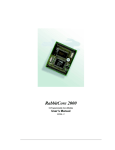
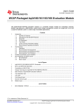
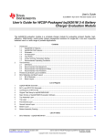
1. Attach RCM2000 to Prototyping Board
Turn the RCM2000 so that the Rabbit 2000 microprocessor is facing as shown below. Plug
RCM2000 headers J1 and J2 on the bottom side of the RCM2000 into the sockets of headers
J1 and J3 on the Prototyping Board.
TP1
RCM2000
Y1
GND
PA0
PA2 C1
PA4
PA6
PB0
PB2
PB4
PB6
PCLK
D7
D5
D3
D1
PE7
PE5
PE3
C7
PE1
/IOW
/BEN
U1
TP3
TP2
R1
R2
C2
JP3
U2
J2
JP1
SRAM
R4 R6 U5
C8
D3
R11
/WDO
J1
R8
VCC
PA1
PA3
PA5
PA7
PB1
PB3
PB5
PB7
GND
D6
D4
D2
D0
PE6
PE4
PE2
PE0
/IOR
C9 R7D2
TP4
A11
A9
A7
A5
A3
A1
STAT
PC1
PC3
PC5
PC7
PD1
PD3
PD5
PD7
VCC
VRAM
SM1
A12
A10
A8
A6
A4
A2
A0
PC0
PC2
PC4
PC6
PD0
PD2
PD4
PD6
GND
VBAT
SM0
/RSTI
/RESO
GND
VCC
Prototyping
Board
J3
J5
PA1
RESET
S2
DS3
S3
PB2
S2 DS3
PA0
+
C1
PB3
S3
U2
J6
RS-232
C5
RXB
TXB
PC3
PC5
PC7
PD1
PD3
PD5
PD7
PC4
PC6
PD0
PD2
PD4
PD6
GND
PC1
PC2
VCC
STAT
PC0
/RSTI
A1
A0
SM1
A3
A2
VRAM
A5
A4
SM0
A7
A6
/RSTO
A9
A8
VCC
A11
A10
C6
GND
C4
GND
RXC TXC
C2
A12
/IOR
PE0
PE2
PE4
PE6
D0
D2
D4
D6
GND
PB7
PB5
PB3
PB1
PA7
PA5
/WDO
/BEN
/IOW
PE1
PE3
PE5
PE7
D1
D3
D5
D7
PCLK
PB6
PB4
PB2
PA6
PA4
U1
C3
J4
DS1
DS2
JP1DS2
J3
PB0
PA3
PA1
J1
S1
VBAT
RCM2000 PROTOTYPING BOARD
Line up the
mounting holes
PA2
VCC
PWR
D2
PA0
GND
J2
RN1
J3
J1
VCC
GND
GND
Figure 1. Attaching RCM2000 to Prototyping Board
NOTE: It is important that you line up the pins on the RCM2000 headers J1 and J2
exactly with the corresponding pins of header sockets J1 and J3 on the Prototyping
Board. The header pins may become bent or damaged if the pin alignment is offset, and
the RCM2000 will not work.
6
RabbitCore RCM2000
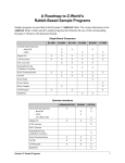
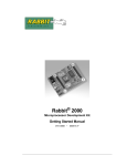
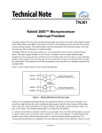
2. Connect RCM2000 to PC
Connect the 10-pin connector of the programming cable labeled PROG to header J3 on the
RCM2000 module as shown in Figure 2 below. Be sure to orient the red edge of the cable
towards pin 1 of the connector. (Do not use the DIAG connector, which is used for a normal
serial connection.)
AC Adapter
The holes shown near
J1 and J2 at the top of
the RCM2000 exist to
align the board for factory
testing. Do not use these
holes for mounting.
RCM2000
Module
TP1
RESET
S2
S3
RXC TXC
RXB
TXB
GND
VCC
PD7
/RSTI
PD5
SM1
PD3
PD6
VRAM
PD1
PD4
VCC
PC7
PD2
SM0
PC5
PD0
GND
PC3
PC6
PE2
PC1
PE4
PE3
PC4
PE6
PE5
STAT
D0
PE7
A1
DIAG
GND
C6
PC2
D2
D1
A3
D4
D3
C5
A0
D6
D5
C4
PROG
Colored side
lines up with
pin 1
J6
RS-232
PC0
GND
D7
C2
A5
PB7
PCLK
J4
DS3
S3
U2
A2
PB5
PB6
VCC
RESET
SWITCH
PB3
A7
PB3
PB4
GND
PB2
A4
PB1
PB2
/RESO
JP1DS2
PA1
C3
/WDO
PA7
PA6
PB0
/IOR
PA5
PE0
PA3
/BEN
PA1
PA4
J2
/RSTI
DS1
DS2
PA0
J3
PE1
VCC
PA2
TP4
PA0
C9 R7D2
GND
C8
D3
S1
VBAT
R4 R6 U5
PWR
D2
S2 DS3
SRAM
A9
JP3
A11
U2
RN1
A12
A10
A8
A6
A4
A2
A0
PC0
PC2
U1
PC4
PC6
+
PD0 C1
PD2
PD4
PD6
GND
VBAT
SM0
A6
C2
J5
J2
A9
A7
A5
A3
A1
STAT
PC1
PC3
PC5
PC7
PD1
PD3
PD5
PD7
VCC
VRAM
SM1
A8
R2
J3A11
JP1
A10
R1
R11
RCM2000 PROTOTYPING BOARD
TP3
TP2
R8
/WDO
GND Y1
PA0
PA2 C1
PA4
U1
PA6
PB0
PB2
PB4
PB6
PCLK
D7
D5
D3
D1
PE7
PE5
PE3
C7
PE1
/IOW
/BEN
A12
J1
PA1
PA3
PA5
PA7
PB1
PB3
PB5
PB7
GND
D6
D4
D2
D0
PE6
PE4
PE2
PE0
/IOR
/IOW
VCC
J1
/RSTO
NOTE:
Prototyping
Board
1
Assemble
AC Adapter
Red
shrink wrap
To
PC COM port
Remove slot cover,
insert tab into slot
2
Snap plug into place
Figure 2. RCM2000 Power and Programming Connections
NOTE: Some PCs now come equipped only with a USB port. It may be possible to use
an RS-232/USB converter (Part No. 20-151-0178) with the programming cable supplied with the RCM2000 Development Kit. Note that not all RS-232/USB converters
work with Dynamic C.
User’s Manual
7
3. Power Supply Connections
When all other connections have been made, you can connect power to the Prototyping
Board.
First, prepare the AC adapter for the country where it will be used by selecting the plug.
The RCM2000 Development Kit presently includes Canada/Japan/U.S., Australia/N.Z.,
U.K., and European style plugs. Snap in the top of the plug assembly into the slot at the
top of the AC adapter as shown in Figure 2, then press down on the spring-loaded clip
below the plug assembly to allow the plug assembly to click into place.
Connect the AC adapter to 3-pin header J5 on the Prototyping Board. The connector may
be attached either way as long as it is not offset to one side.
Plug in the AC adapter. The power LED on the Prototyping Board should light up. The
RCM2000 and the Prototyping Board are now ready to be used.
NOTE: A RESET button is provided on the Prototyping Board to allow a hardware reset.
To power down the Prototyping Board, unplug the power connector from J5. You should
disconnect power before making any circuit adjustments in the prototyping area, changing
any connections to the board, or removing the RCM2020 from the Prototyping Board.
2.1.1 Alternate Power Supply Connections
Development kits sold outside North America before 2009 included a header connector
that could be connected to 3-pin header J5 on the Prototyping Board. The red and black
wires from the connector could then be connected to the positive and negative connections
on your power supply. The power supply should deliver 8 V–24 V DC at 8 W.
8
RabbitCore RCM2000
2.2 Run a Sample Program
Once the RCM2000 is connected as described in the preceding pages, start Dynamic C by
double-clicking on the Dynamic C icon on your desktop or in your Start menu. Dynamic C
uses the serial port specified during installation.
If you are using a USB port to connect your computer to the RCM2000 module, choose
Options > Project Options and select “Use USB to Serial Converter” under the
Communications tab, then click OK.
Find the file PONG.C, which is in the Dynamic C SAMPLES folder. To run the program,
open it with the File menu (if it is not still open), then compile and run it by pressing F9 or
by selecting Run in the Run menu. The STDIO window will open and will display a small
square bouncing around in a box.
2.2.1 Troubleshooting
If Dynamic C cannot find the target system (error message "No Rabbit Processor
Detected."):
• Check that the RCM2000 is powered correctly — the red power LED on the Prototyping
Board should be lit when the RCM2000 is mounted on the Prototyping Board and the AC
adapter is plugged in.
• Check both ends of the programming cable to ensure that they are firmly plugged into
the PC and the PROG connector, not the DIAG connector, is plugged in to the programming port on the RCM2000 with the marked (colored) edge of the programming cable
towards pin 1 of the programming header.
• Ensure that the RCM2000 module is firmly and correctly installed in its connectors on
the Prototyping Board.
• Dynamic C uses the COM port specified during installation. Select a different COM
port within Dynamic C. From the Options menu, select Project Options, then select
Communications. Select another COM port from the list, then click OK. Press
<Ctrl-Y> to force Dynamic C to recompile the BIOS. If Dynamic C still reports it is
unable to locate the target system, repeat the above steps until you locate the COM port
used by the programming cable.
If Dynamic C appears to compile the BIOS successfully, but you then receive a communication error message when you compile and load the sample program, it is possible that
your PC cannot handle the higher program-loading baud rate. Try changing the maximum
download rate to a slower baud rate as follows.
• Locate the Serial Options dialog in the Dynamic C Options > Project Options >
Communications menu. Select a slower Max download baud rate.
If a program compiles and loads, but then loses target communication before you can
begin debugging, it is possible that your PC cannot handle the default debugging baud
rate. Try lowering the debugging baud rate as follows.
• Locate the Serial Options dialog in the Dynamic C Options > Project Options >
Communications menu. Choose a lower debug baud rate.
User’s Manual
9
2.3 Where Do I Go From Here?
If everything appears to be working, we recommend the following sequence of action:
1. Run all of the sample programs described in Chapter 3 to get a basic familiarity with
Dynamic C and the RCM2000’s capabilities.
2. For further development, refer to the RabbitCore RCM2000 User’s Manual for details
of the module’s hardware and software components.
A documentation icon should have been installed on your workstation’s desktop; click
on it to reach the documentation menu. You can create a new desktop icon that points to
default.htm in the docs folder in the Dynamic C installation folder.
3. For advanced development topics, refer to the Dynamic C User’s Manual, also in the
online documentation set.
2.3.1 Technical Support
NOTE: If you purchased your RCM2000 through a distributor or through a Rabbit partner,
contact the distributor or partner first for technical support.
• Use the Dynamic C Help menu to get further assistance with Dynamic C.
• Check the Rabbit Technical Bulletin Board and forums at www.rabbit.com/support/bb/
and at www.rabbit.com/forums/.
• Use the Technical Support e-mail form at www.rabbit.com/support/.
10
RabbitCore RCM2000
3. RUNNING SAMPLE PROGRAMS
To develop and debug programs for the RCM2000 (and for all
other Rabbit hardware), you must install and use Dynamic C.
Dynamic C is an integrated development system for writing
embedded software. It runs on an IBM-compatible PC and is
designed for use with Rabbit single-board computers and other
single-board computers based on the Rabbit microprocessor.
Chapter 3 provides the sample programs related to the RCM2000.
3.1 Sample Programs
To help familiarize you with the RCM2000 modules, Dynamic C includes several sample
programs in the Dynamic C SAMPLES\RCM2000 directory. Loading, executing and studying these programs will give you a solid hands-on overview of the RCM2000’s
capabilities, as well as a quick start with Dynamic C as an application development tool.
These programs are intended to serve as tutorials, but then can also be used as starting
points or building blocks for your own applications.
NOTE: It is assumed in this section that you have at least an elementary grasp of ANSI C.
If you do not, see the introductory pages of the Dynamic C User’s Manual for a suggested reading list.
Each sample program has comments that describe the purpose and function of the program.
Before running any of these sample program, make sure that your RCM2000 is connected
to the Prototyping Board and to your PC as described in Section 2.1, “Connections.”
To run a sample program, open it with the File menu (if it is not already open), then compile and run it by pressing F9 or by selecting Run in the Run menu.
Complete information on Dynamic C is provided in the Dynamic C User’s Manual.
User’s Manual
11
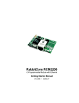
3.1.1 Running Sample Program FLASHLED.C
This sample program will be used to illustrate some of the functions of Dynamic C.
First, open the file FLASHLED.C, which is in the SAMPLES/RCM2000 folder. The program
will appear in a window, as shown in Figure 3 below (minus some comments). Use the
mouse to place the cursor on the function name WrPortI in the program and type <Ctrl-H>.
This will bring up a documentation box for the function WrPortI. In general, you can do
this with all functions in Dynamic C libraries, including libraries you write yourself. Close
the documentation box and continue.
C programs begin with main
Set up Port A to output
to LED DS2 and DS3
main(){
int j;
WrPortI(SPCR,&SPCRShadow,0x84);
WrPortI(PADR,&PADRShadow,0xFF);
Start a loop
Turn LED DS3 off
while(1) {
BitWrPortI(PADR,&PADRShadow,1,1);
for(j=0; j<32000; j++);
Time delay by counting
to 32,000
BitWrPortI(PADR,&PADRShadow,0,1);
Turn LED DS3 on
for(j=0; j<25000; j++);
} // end while
} //
end of main
Time delay by counting
to 25,000
End of the endless loop
Note: See the Rabbit 2000 Microprocessor User’s Manual
(Software Chapter) for details on the routines that read and
write I/O ports.
Figure 3. Sample Program FLASHLED.C
To run the program FLASHLED.C, open it with the File menu (if it is not already open),
then compile and run it by pressing F9 or by selecting Run in the Run menu. The LED on
the Prototyping Board should start flashing if everything went well. If this doesn’t work
review the following points.
• The target should be ready, which is indicated by the message “BIOS successfully compiled...” If you did not receive this message or you get a communication error, recompile the BIOS by typing <Ctrl-Y> or select Recompile BIOS from the Compile menu.
12
RabbitCore RCM2000
• A message reports “No Rabbit Processor Detected” in cases where the RCM2000 and
the Prototyping Board are not connected together, the wall transformer is not connected, or is not plugged in. (The red power LED lights whenever power is connected.)
• The programming cable must be connected to the RCM2000. (The colored wire on the
programming cable is closest to pin 1 on header J3 on the RCM2000, as shown in
Figure 2.) The other end of the programming cable must be connected to the PC serial
port. The COM port specified in the Dynamic C Options menu must be the same as the
one the programming cable is connected to.
• To check if you have the correct serial port, select Compile, then Compile BIOS, or
type <Ctrl-Y>. If the “BIOS successfully compiled …” message does not display, try a
different serial port using the Dynamic C Options menu until you find the serial port
you are plugged into. Don’t change anything in this menu except the COM number.
The baud rate should be 115,200 bps and the stop bits should be 1.
3.1.1.1 Single-Stepping
Compile or re-compile FLASHLED.C by clicking the Compile button on the task bar. The
program will compile and the screen will come up with a highlighted character (green) at
the first executable statement of the program. Use the F8 key to single-step. Each time the
F8 key is pressed, the cursor will advance one statement. When you get to the for(j=0,
j< ... statement, it becomes impractical to single-step further because you would have
to press F8 thousands of times. We will use this statement to illustrate watch expressions.
3.1.1.2 Watch Expressions
Type <Ctrl-W> or chose Add/Del Watch Expression in the Inspect menu. A box will
come up. Type the lower case letter j and click on add to top and close. Now continue single-stepping with F8. Each time you step, the watch expression (j) will be evaluated and
printed in the watch window. Note how the value of j advances when the statement j++ is
executed.
3.1.1.3 Break Point
Move the cursor to the start of the statement:
for(j=0; j<25000; j++);
To set a break point on this statement, type F2 or select Toggle Breakpoint from the Run
menu. A red highlight will appear on the first character of the statement. To get the program running at full speed, type F9 or select Run on the Run menu. The program will
advance until it hits the break point. Then the break point will start flashing and show both
red and green colors. Note that LED DS3 is now solidly turned on. This is because we
have passed the statement turning on LED DS3. Note that j in the watch window has the
value 32000. This is because the loop above terminated when j reached 32000.
To remove the break point, type F2 or select Toggle Breakpoint on the Run menu. To
continue program execution, type F9 or select Run from the Run menu. Now the LED
should be flashing again since the program is running at full speed.
User’s Manual
13
You can set break points while the program is running by positioning the cursor to a statement and using the F2 key. If the execution thread hits the break point, a break point will
take place.You can toggle the break point off with the F2 key and continue execution with
the F9 key. Try this a few times to get the feel of things.
3.1.1.4 Editing the Program
Click on the Edit box on the task bar. This will set Dynamic C into the edit mode so that
you can change the program. Use the Save as choice on the File menu to save the file
with a new name so as not to change the demo program. Save the file as MYTEST.C. Now
change the number 25000 in the for (.. statement to 10000. Then use the F9 key to
recompile and run the program. The LED will start flashing, but it will flash much faster
than before because you have changed the loop counter terminal value from 25000 to
10000.
3.1.1.5 Watching Variables Dynamically
Go back to edit mode (select edit) and load the program FLASHLED2.C using the File
menu Open command. This program is the same as the first program, except that a variable k has been added along with a statement to increment k each time around the endless
loop. The statement:
runwatch();
has been added. This is a debugging statement that makes it possible to view variables
while the program is running.
Use the F9 key to compile and run FLASHLED2.C. Now type <Ctrl-W> to open the watch
window and add the watch expression k to the top of the list of watch expressions. Now
type <Ctrl-U>. Each time you type <Ctrl-U>, you will see the current value of k, which is
incrementing about 5 times a second.
As an experiment, add another expression to the watch window:
k*5
Then type <ctrl-U> several times to observe the watch expressions k and k*5.
3.1.1.6 Summary of Features
So far you have practiced using the following features of Dynamic C.
• Loading, compiling and running a program. When you load a program it appears in an
edit window. You can compile by selecting Compile on the task bar or from the Compile menu. When you compile the program, it is compiled into machine language and
downloaded to the target over the serial port. The execution proceeds to the first statement of main where it pauses, waiting for you to command the program to run, which
you can do with the F9 key or by selecting Run on the Run menu. If want to compile
and start the program running with one keystroke, use F9, the run command. If the program is not already compiled, the run command will compile it first.
• Single-stepping. This is done with the F8 key. The F7 key can also be used for singlestepping. If the F7 key is used, then descent into subroutines will take place. With the
F8 key the subroutine is executed at full speed when the statement that calls it is
stepped over.
14
RabbitCore RCM2000
• Setting break points. The F2 key is used to turn on or turn off (toggle) a break point at
the cursor position if the program has already been compiled. You can set a break point
if the program is paused at a break point. You can also set a break point in a program
that is running at full speed. This will cause the program to break if the execution
thread hits your break point.
• Watch expressions. A watch expression is a C expression that is evaluated on command
in the watch window. An expression is basically any type of C formula that can include
operators, variables and function calls, but not statements that require multiple lines
such as for or switch. You can have a list of watch expressions in the watch window. If
you are single-stepping, then they are all evaluated on each step. You can also command the watch expression to be evaluated by using the <Ctrl-U> command. When a
watch expression is evaluated at a break point, it is evaluated as if the statement was at
the beginning of the function where you are single-stepping. If your program is running
you can also evaluate watch expressions with a <Ctrl-U> if your program has a
runwatch() command that is frequently executed. In this case, only expressions
involving global variables can be evaluated, and the expression is evaluated as if it
were in a separate function with no local variables.
3.1.1.7 Cooperative Multitasking
Cooperative multitasking is a convenient way to perform several different tasks at the
same time. An example would be to step a machine through a sequence of steps and at the
same time independently carry on a dialog with the operator via a human interface. Cooperative multitasking differs from another approach called preemptive multitasking.
Dynamic C supports both types of multitasking. In cooperative multitasking each separate
task voluntarily surrenders its compute time when it does not need to perform any more
activity immediately. In preemptive multitasking control is forcibly removed from the task
via an interrupt.
Dynamic C has language extensions to support multitasking. The major C constructs are
called costatements, cofunctions, and slicing. These are described more completely in the
Dynamic C User’s Manual. The example below, sample program FLASHLEDS2.C, uses
costatements. A costatement is a way to perform a sequence of operations that involve
pauses or waits for some external event to take place. A complete description of costatements is in the Dynamic C User’s Manual. The FLASHLEDS2.C sample program has two
independent tasks. The first task flashes LED DS2 2.5 times a second. The second task
flashes DS3 every 1.5 seconds.
User’s Manual
15
#define DS2 0
#define DS3 1
// predefine for LED DS2
// predefine for LED DS3
// This cofunction flashes LED on for ontime, then off
cofunc flashled[4](int led, int ontime, int offtime) {
for(;;) {
waitfor(DelayMs(ontime));
WrPortI(PADR,&PADRShadow,(1<<led)|PADR);
waitfor(DelayMs(offtime);
WrPortI(PADR,&PADRShadow,(1<<led)^0xff&PADR);
}
}
main {
// Initialize ports
WrPortI(SPCR,&SPCRShadow,0x84);
WrPortI(PEFR,&PEFRShadow,0x00);
WrPortI(PEDDR,&PEDDRShadow,0x01);
WrPortI(PECR,&PECRShadow,0x00);
}
//
//
//
//
Set
Set
Set
Set
for offtime
//
//
//
//
on delay
turn LED off
off delay
turn LED on
Port A all outputs, LEDs on
Port E normal I/O
Port E bits 7…1 input, 0 output
transfer clock as pclk/2
for(;;) {
// run forever
costate {
// start costatement
wfd {
// use wfd (waitfordone) with cofunctions
flashled[0](DS2,200,200); // flash DS2 on 200 ms, off 200 ms
flashled[1](DS3,1000,500);// flash DS3 on 1000 ms, off 500 ms
}
}
// end costatement
}
// end for loop
// end of main, never come here
The flashing of the LEDs is performed by the costatement. Costatements need to be executed regularly, often at least every 25 ms. To accomplish this, the costatements are
enclosed in a while loop or a for loop. The term while loop is used as a handy way to
describe a style of real-time programming in which most operations are done in one loop.
The costatement is executed on each pass through the big loop. When a waitfor or a wfd
condition is encountered the first time, the current value of MS_TIMER is saved and then
on each subsequent pass the saved value is compared to the current value. If a waitfor
condition is not encountered, then a jump is made to the end of the costatement, and on the
next pass of the loop, when the execution thread reaches the beginning of the costatement,
execution passes directly to the waitfor statement. The costatement has the property that
it can wait for long periods of time, but not use a lot of execution time. Each costatement
is a little program with its own statement pointer that advances in response to conditions.
On each pass through the big loop, as little as one statement in the costatement is executed, starting at the current position of the costatement’s statement pointer. Consult the
Dynamic C User’s Manual for more details.
This program also illustrates a use for a shadow register. A shadow register is used to keep
track of the contents of an I/O port that is write only—it can’t be read back. If every time a
write is made to the port the same bits are set in the shadow register, then the shadow register has the same data as the port register.
16
RabbitCore RCM2000
3.1.1.8 Advantages of Cooperative Multitasking
Cooperative multitasking, as implemented with language extensions, has the advantage of
being intuitive. Unlike preemptive multitasking, variables can be shared between different
tasks without having to take elaborate precautions. Sharing variables between tasks is the
greatest cause of bugs in programs that use preemptive multitasking. It might seem that
the biggest problem would be response time because of the big loop time becoming long
as the program grows. Our solution for that is called slicing, which is further described in
the Dynamic C User’s Manual.
User’s Manual
17
3.1.2 Getting to Know the RCM2000
The following sample programs can be found in the SAMPLES\RCM2000 folder.
• EXTSRAM.C—demonstrates the setup and simple addressing to an external SRAM.
This program first maps the external SRAM to the I/O Bank 0 register with a maximum
of 15 wait states, chip select strobe (which is ignored because of the circuitry), and
allows writes. The first 256 bytes of SRAM are cleared and read back. Values are then
written to the same area and are read back. The Dynamic C STDIO window will indicate if writes and reads did not occur
Connect an external SRAM as shown below before you run this sample program.
8K × 8
SRAM
RCM2000
Core Module
A0A12
A0A12
D0D7
D0D7
/WE
/OE
/CE
/IOW
/IOR
/BEN
• FLASHLED.C—repeatedly flashes LED DS3 on the Prototyping Board on and off.
LED DS3 is controlled by Parallel Port A bit 1 (PA1).
• FLASHLED2.C—repeatedly flashes LED DS3 on the Prototyping Board on and off.
LED DS3 is controlled by Parallel Port A bit 1 (PA1).
This sample program also shows the use of the runwatch() function to allow
Dynamic C to update watch expressions while running. The following steps explain
how to do this.
1. Add a watch expression for "k" in the Inspect > Add Watch dialog box.
2. Click "Add" or "Add to top" so that it will be in the watch list permanently.
3. Click OK to close the dialog box.
4. Press <Ctrl+U> while the program is running. This will update the watch window
18
RabbitCore RCM2000
• FLASHLEDS.C—demonstrates the use of coding with assembly instructions, cofunctions, and costatements to flash LEDs DS2 and DS3 on the Prototyping Board on and
off. LEDs DS2 and DS3 are controlled by Parallel Port A bit 0 (PA0) and Parallel Port
A bit 1 (PA1).Once you have compile this program and it is running, LEDs DS2 and
DS3 will flash on/off at different rates.
• FLASHLEDS2.C—demonstrates the use of cofunctions and costatements to flash LEDs
DS2 and DS3 on the Prototyping Board on and off. LEDs DS2 and DS3 are controlled
by Parallel Port A bit 0 (PA0) and Parallel Port A bit 1 (PA1).Once you have compile
this program and it is running, LEDs DS2 and DS3 will flash on/off at different rates.
• KEYLCD.C—demonstrates a simple setup for a 2 × 6 keypad and a 2 × 20 LCD.
Connect the keypad to Parallel Ports B, C, and D.
PB0—Keypad Col 0
PC1—Keypad Col 1
PB2—Keypad Col 2
PB3—Keypad Col 3
PB4—Keypad Col 4
PB5—Keypad Col 5
PD6—Keypad Row 0
PD7—Keypad Row 1
RCM2000
Prototyping Board
VCC
J2
11
13
14
15
16
J4
29
Keypad
10 kW
resistors
PB0
PB2
PB3
PB4
PB5
Col 0
Col 2
Col 3
Col 4
Col 5
PC1
PD6
PD7
16
30
Col 1
Row 0
Row 1
NC
NC
Connect the LCD to Parallel Port A.
RCM2000
Prototyping Board
8
9
10
680 W
100 nF
7
1 kW
6
3
470 W
5
PA1
PA2
PA3
PA4
PA5
PA6
PA7
2.2 kW
4
4.7 kW
20 kW
J1
2x20 LCD
VLC
10 kW
PA0—backlight (if connected)
PA1—LCD /CS
PA2—LCD RS (High = Control,
Low = Data) / LCD Contrast 0
PA3—LCD /WR/ LCD Contrast 1
PA4—LCD D4 / LCD Contrast 2
PA5—LCD D5 / LCD Contrast 3
PA6—LCD D6 / LCD Contrast 4
PA7—LCD D7 / LCD Contrast 5
2
6
4
5
11
12
13
14
7
8
9
10
VLC
VCC
/CS
RS
/WR
D4
D5
D6
D7
D0
D1
D2
D3
Once the connections have been made and the sample program is running, the LCD
will display two rows of 6 dots, each dot representing the corresponding key. When a
key is pressed, the corresponding dot will become an asterisk.
User’s Manual
19
• LCD_DEMO.C—demonstrates a simple setup for an LCD that uses the HD44780 controller or an equivalent.
Connect the LCD to the RCM2000 address and data lines on the Prototyping Board.
D0—DB0
D1—DB1
D2—DB2
D3—DB3
D4—DB4
D5—DB5
D6—DB6
D7—DB7
2x20 LCD
DB0DB7
D0D7
RCM2000
Prototyping Board
D7D0 are pins 2128
on header J2
A0A1
A1A0 are pins 1213
on header J4
2x20 LCD
D0D7
DB0DB7
A0A1
HEADER J2:
38 37
36
35
/PE0 /IOR /IOW /PE1
E
E
A0—RS (Register Select: 0 = command, 1 = data)
A1—R/W (0=write, 1=read)
*—E (normally low: latches on high-to-low transition)
• SWTEST.C—demonstrates the use of pushbutton switches S2 and S3 to toggle LEDs
DS2 and DS3 on the Prototyping Board on and off.
Parallel Port A bit 0 = LED DS2
Parallel Port A bit 1 = LED DS3
Parallel Port B bit 2 = switch S2
Parallel Port B bit 3 = switch S3
• TOGGLELED.C—demonstrates the use of costatements to detect switch presses using
the press-and-release method of debouncing. As soon as the sample program starts running, LED DS3 on the Prototyping Board (which is controlled by PA1) starts flashing
once per second. Press switch S2 on the Prototyping Board (which is connected to PB2)
to toggle LED DS2 on the Prototyping Board (which is controlled by PA0). The pushbutton switch is debounced by the software.
20
RabbitCore RCM2000
3.1.3 Serial Communication
The following sample programs can be found in the SAMPLES\RCM2000 folder.
PWR
D2
S1
DS1
DS2
PA1
DS3
2
23
X
A
M
S3
PA0
PB2
S2
JP1DS2
U1
C1+
RESET
J5
RN1
S2 DS3
PB3
S3
C2
U2
C3
RS-232
C4
C5
J6
RXC TXC
Two sample programs, CORE_FLOWCONTROL.C and CORE_PARITY.C,
are available to illustrate RS-232
communication. To run these sample
programs, you will have to add an
RS-232 transceiver such as the
MAX232 at location U2 and four
100 nF charge-storage capacitors at
C3–C6 on the Prototyping Board.
Also install the 2 × 5 IDC header
included with the Prototyping Board
accessory parts at J6 to interface the
RS-232 signals.
GND
RXB
TXB
C6
100 nF
storage
capacitors
The diagram shows the connections.
• CORE_FLOWCONTROL.C—This
program demonstrates hardware flow control by configuring Serial Port C (PC3/PC2)
for CTS/RTS with serial data coming from TxB at 115,200 bps. One character at a time
is received and is displayed in the STDIO window.
To set up the Prototyping Board, you will need to tie PC4 and PC5
(TxB and RxB) together at header J4, and you will also tie PC2 and
PC3 (TxC and RxC) together as shown in the diagram.
RxC TxC
J6
TxB RxB GND
A repeating triangular pattern should print out in the STDIO window.
The program will periodically switch flow control on or off to demonstrate the effect of no flow control.
Refer to the serBflowcontrolOn() function call in the Dynamic C Function Reference Manual for a general description on how to set up flow control lines.
• CORE_PARITY.C—This program demonstrates the use of parity modes by repeatedly
sending byte values 0–127 from Serial Port B to Serial Port C. The program will switch
between generating parity or not on Serial Port B. Serial Port C will always be checking
parity, so parity errors should occur during every other sequence.
To set up the Prototyping Board, you will need to tie PC4 and PC3
(TxB and RxC) together at header J4 as shown in the diagram.
RxC TxC
The Dynamic C STDIO window will display the error sequence.
TxB RxB GND
User’s Manual
J6
21
22
RabbitCore RCM2000
4. HARDWARE REFERENCE
Chapter 4 describes the principal subsystems for the RCM2000.
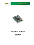
4.1 RCM2000 Digital Inputs and Outputs
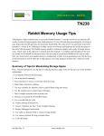
Figure 4 shows the subsystems designed into the RCM2000.
PA0PA7
Port A
4x CMOS
synchronous/
asynchronous
PCLK
RESET
WDO
Serial Ports
(Port C)
Programming
Port
PB0
PB5
PB6
PB7
Port B
RCM2000
Misc. Outputs
Real-Time Clock
Watchdog
7 Timers
Slave Port
Clock Doubler
RAM
Backup Battery
Support
PD0PD7
Port D
Port E
PE0PE7
Address Lines
A0A12
I/O Control
IORD
IOWR
BUFEN
Data Lines
DA0DA7
Flash
Figure 4. Rabbit Subsystems
User’s Manual
23
The RCM2000 has 40 parallel I/O lines grouped in five 8-bit ports available on headers J1
and J2. The 24 bidirectional I/O lines are located on pins PA0–PA7, PD0-PD7, and PE0PE7. The pinouts for headers J1 and J2 are shown in Figure 5.
J2
A12
A10
A8
A6
A4
A2
A0
PC0
PC2
PC4
PC6
PD0
PD2
PD4
PD6
GND
VBAT
SMODE0
/RES_OUT
VCC
J1
A11
A9
A7
A5
A3
A1
STATUS
PC1
PC3
PC5
PC7
PD1
PD3
PD5
PD7
VCC
VRAM
SMODE1
/RES_IN
GND
GND
PA0
PA2
PA4
PA6
PB0
PB2
PB4
PB6
PCLK
D7
D5
D3
D1
PE7
PE5
PE3
PE1
/IOWR
/BUFEN
VCC
PA1
PA3
PA5
PA7
PB1
PB3
PB5
PB7
GND
D6
D4
D2
D0
PE6
PE4
PE2
PE0
/IORD
/WDO
Note: These are the pinouts as seen on the
Bottom Side of the RCM2000.
Figure 5. RCM2000 Pinout
24
RabbitCore RCM2000
The ports on the Rabbit 2000 microprocessor used in the RCM2000 are configurable, and
so the factory defaults can be reconfigured. Table 2 lists the Rabbit 2000 factory defaults
and the alternate configurations.
Table 2. RCM2000 Pinout Configurations
Pin
Pin Name
1, 20
GND
2
VCC
Default Use
Alternate Use
PA[0:7]
Parallel I/O
Slave port data bus
SD0–SD7
11
PB0
Input
Serial port clock CLKB
12
PB1
Input
Serial port clock CLKA
13
PB2
Input
Slave port write /SWR
14
PB3
Input
Slave port read /SRD
15
PB4
Input
SA0
16
PB5
Input
SA1
17
PB6
Output
18
PB7
Output
Slave port attention line
/SLAVEATTN
19
PCLK
Output (Internal Clock)
Output
21–28
D[7:0]
Input/Output
3–10
Notes
CLKA is connected to
programming port (header
J3, pin 3)
Header J1
Slave port address lines
Rabbit 2000 data bus
29
PE7
I7 output or slave port chip
select /SCS
30
PE6
I6 output
31
PE5
I5 output or INT1B input
32
PE4
33
PE3
I3 output
34
PE2
I2 output
35
PE1
I1 output or INT1A input
36
PE0
I0 output or INT0A input
37
/IOWR
Output (I/O write strobe)
38
/IORD
Output (I/O read strobe)
39
/BUFEN
Output (I/O buffer enable)
40
/WDO
Output (Watchdog output)
User’s Manual
Bitwise or parallel
programmable I/O
Turned off in software
I4 output or INT0B input
May also be used to output
a 30 µs pulse
Outputs a pulse when the
internal watchdog times
out
25
Table 2. RCM2000 Pinout Configurations (continued)
Header J2
Pin
Default Use
Alternate Use
A[12:0]
14
STAT
Output (Status)
Output
15
PC0
Output
TXD
16
PC1
Input
RXD
17
PC2
Output
TXC
18
PC3
Input
RXC
19
PC4
Output
TXB
20
PC5
Input
RXB
21
PC6
Output
TXA
22
PC7
Input
RXA
21
PC6
Output
TXA
22
PC7
Input
RXA
23–26
PD[0:3]
27
PD4
28
PD5
Bitwise or parallel
ATXB output
programmable I/O, can be
driven or open-drain output ARXB input
29
PD6
ATXA output
30
PD7
ARXA input
31, 40
GND
32, 39
VCC
33
VBATR
3 V battery input
34
VRAM
2.1 V output
100 kΩ minimum load
(0,0)—start executing at
address zero
No programming cable
attached
SMODE0,
SMODE1
37
/RES_OUT
38
/RES_IN
Output
Notes
1–13
35–36
26
Pin Name
Rabbit 2000 address bus
Connected to programming port
16 mA sourcing and
sinking current at full AC
switching speed
SMODE0 =1, SMODE1 = 1
Cold boot from asynchronous serial port A at 2400
bps (programming cable
connected)
(0,1)—cold boot from slave
port
With programming cable
attached
(1,0)—cold boot from
clocked serial port A
Reset Output
Reset Input
RabbitCore RCM2000
As shown in Table 2, pins PA0–PA7 can be used to allow the Rabbit 2000 to be a slave to
another processor. PE0, PE1, PE4, and PE5 can be used as external interrupts INT0A,
INT1A, INT0B, and INT1B. Pins PB0 and PB1 can be used to access the clock on Serial
Port B and Serial Port A of the Rabbit microprocessor. Pins PD4 and PD6 can be programmed to be optional serial outputs for Serial Ports B and A. PD5 and PD7 can be used
as alternate serial inputs by Serial Ports B and A.
4.1.1 Dedicated Inputs
PB0 and PB1 are designated as inputs because the Rabbit 2000 is operating in an asynchronous mode. Four of the input-only pins are located on PB2–PB5. When Port C is used
as a parallel port, PC1, PC3, PC5, and PC7 are also inputs only. All the inputs are pulled up
with 47 kΩ resistors. Figure 6 shows the locations of these pullup resistors.
Bottom Side
Q10
U1
TP3
TP2
R1
R2
C2
U2
JP3
JP1
SRAM
A6
A5
A4
A3
A2
A1
A0
STAT
PC0
PC1
R16
JP2
R28
PC2
PC3
PC4
PC5
PC6
PC7
U10
PD5
PD6
PD7
GND
VCC
VBAT
VRAM
VCC
GND
R36
C19
D1
RT1
/RSTI
R14
R12
SM1
C18
PD4
VCC
PA1
PA2
PA3
PA5
PA6
PA7
PB0
PB1
PB2
PB3
PB4
Flash
EPROM
R41
PD3
C12
U11
J1
PA0
PA4
R27
C10
C13
R42
PD1
PD2
SM0
Q14
C6
PD0
/RESO
C11
C3
R5
R39
J3
VCC
A7
Q13
R40
GND
TP4
A8
GND
R15
R38
/RESO
A9
R37
/RSTI
A10
C16
A12
A10
A8
A6
A4
A2
A0
PC0
PC2
PC4
PC6
PD0
PD2
PD4
PD6
GND
VBAT
SM0
Q11
C15
R11
C8 C9 R7D2
D3
A11
A9
A7
A5
A3
A1
STAT
PC1
PC3
PC5
PC7
PD1
PD3
PD5
PD7
VCC
VRAM
SM1
A11
R35
R4 R6 U5
R8
/WDO
Y1
GND
PA0
PA2 C1
PA4
PA6
PB0
PB2
PB4
PB6
PCLK
D7
D5
D3
D1
PE7
PE5
PE3
C7
PE1
/IOW
/BEN
A12
R9
{
R21
R22
R23
R24
R25
R26
VCC
PA1
PA3
PA5
PA7
PB1
PB3
PB5
PB7
GND
D6
D4
D2
D0
PE6
PE4
PE2
PE0
/IOR
J2
R3
TP1
J1
R34
Parallel Port B
Input Pullup Resistors
Top Side
PB5
PB6
PB7
PCLK
GND
D7
D6
D5
D4
D3
D2
D1
D0
PE7
PE6
PE5
PE4
PE3
PE2
PE1
PE0
/IOW
/IOR
/BEN
/WDO
175-0201
Parallel Port C
Input Pullup Resistors
Figure 6. Locations of Digital Input Pullup Resistors
NOTE: All the digital input pullup resistors are located on the bottom side of RCM2000
boards marked 175-0168
PB2–PB5 can instead be used for the slave port. PB2 and PB3 are slave write and slave
read strobes, while PB4 and PB5 serve as slave address lines SA0 and SA1, and are used
to access the slave registers (SD0–SD7), which is the alternate assignment for Parallel
Port A. Parallel Port C pins PC1, PC3, PC5, and PC7 are inputs only can alternately be
selectively enabled to serve as the serial data inputs for Serial Ports D, C, B, and A.
4.1.2 Dedicated Outputs
Two of the output-only pins are located on PB6–PB7. PB7 can also be used with the slave
port as the /SLAVEATTN output. This configuration signifies that the slave is requesting
attention from the master. When Port C is used as a parallel port, PC0, PC2, PC4 and PC6
are outputs only. These pins can alternately serve as the serial data outputs for Serial Ports
D, C, B, and A.
User’s Manual
27
4.2 Memory I/O Interface
Thirteen of the Rabbit 2000 address lines (A0–A12) and all the data lines (D0–D7) are
available as outputs on the RCM2000. I/0 write (/IOWR), I/0 read (/IORD), buffer enable
(/BUFEN), and Watchdog Output (/WDO) are also available for interfacing to external
devices.
The STATUS output has three different programmable functions:
1. It can be driven low on the first op code fetch cycle.
2. It can be driven low during an interrupt acknowledge cycle.
3. It can also serve as a general-purpose output.
4.2.1 Additional I/0
Although, the output clock is available on the PCLK pin, the output clock is disabled in
software starting with Dynamic C v 7.02 and later. This reduces radiated emissions. The
primary function of PCLK is as a peripheral clock or a peripheral clock ÷ 2, but PCLK can
instead be used as a digital output. See Section 5.2.1, “PCLK Output,” for more information.
Two status mode pins, SMODE0 and SMODE1, are available as inputs. The logic state of
these two pins determines the startup procedure after a reset. /RES_IN is an external input
used to reset the Rabbit 2000 microprocessor and RCM2000 memory. /RES_OUT is an
output from the reset circuitry that can be used to reset other peripheral devices.
4.3 Serial Communication
The RCM2000 does not have an RS-232 or an RS-485 transceiver directly on the board.
However, the Prototyping Board does support a industry standard RS-232 transceiver
chip. See Appendix B, “Prototyping Board,” for more information.
4.3.1 Serial Ports
There are four serial ports designated as Serial Ports A, B, C, and D. All four serial ports
can operate in an asynchronous mode up to the baud rate of the system clock divided by
32. An asynchronous port can handle 7 or 8 data bits. A 9th bit address scheme, where an
additional bit is sent to mark the first byte of a message, is also supported. Serial Ports A
and B can be operated alternately in the clocked serial mode. In this mode, a clock line
synchronously clocks the data in or out. Either of the two communicating devices can supply the clock. When the Rabbit provides the clock, the baud rate can be up to 1/4 of the
system clock frequency, or more than 6.45 Mbps for a 25.8 MHz clock speed.
28
RabbitCore RCM2000
4.3.2 Programming Port
The RCM2000 has a 10-pin program header labeled J3. The programming port uses the
Rabbit 2000’s Serial Port A for communication. Dynamic C uses the programming port to
download and debug programs.
The programming port is also used for the following operations.
• Cold-boot the Rabbit 2000 after a reset.
• Remotely download and debug a program over an Ethernet connection using the
RabbitLink EG2110.
• Fast copy designated portions of flash memory from one Rabbit-based board (the
master) to another (the slave) using the Rabbit Cloning Board.
Alternate Uses of the Serial Programming Port
All three clocked Serial Port A signals are available as
• a synchronous serial port
• an asynchronous serial port, with the clock line usable as a general CMOS input
The serial programming port may also be used as a serial port via the DIAG connector on
the serial programming cable.
In addition to Serial Port A, the Rabbit 2000 startup-mode (SMODE0, SMODE1), status,
and reset pins are available on the serial programming port.
The two startup mode pins determine what happens after a reset—the Rabbit 2000 is
either cold-booted or the program begins executing at address 0x0000. These two
SMODE pins can be used as general inputs once the cold boot is complete.
The status pin is used by Dynamic C to determine whether a Rabbit microprocessor is
present. The status output has three different programmable functions:
1. It can be driven low on the first op code fetch cycle.
2. It can be driven low during an interrupt acknowledge cycle.
3. It can also serve as a general-purpose output.
The /RESET_IN pin is an external input that is used to reset the Rabbit 2000 and the
onboard peripheral circuits on the RabbitCore module. The serial programming port can be
used to force a hard reset on the RabbitCore module by asserting the /RESET_IN signal.
Refer to the Rabbit 2000 Microprocessor User’s Manual for more information.
User’s Manual
29
4.4 Serial Programming Cable
The programming cable is used to connect the RCM2000’s programming port to a PC
serial COM port. The programming cable converts the RS-232 voltage levels used by the
PC serial port to the TTL voltage levels used by the Rabbit 2000.
When the PROG connector on the programming cable is connected to the RCM2000’s
programming header, programs can be downloaded and debugged over the serial interface.
The DIAG connector of the programming cable may be used on the RCM2000’s programming header with the RCM2000 operating in the Run Mode. This allows the programming
port to be used as a regular serial port.
4.4.1 Changing Between Program Mode and Run Mode
The RCM2000 is automatically in Program Mode when the PROG connector on the
programming cable is attached to the RCM2000, and is automatically in Run Mode when
no programming cable is attached. When the Rabbit 2000 is reset, the operating mode is
determined by the status of the SMODE pins. When the programming cable’s PROG
connector is attached, the SMODE pins are pulled high, placing the Rabbit 2000 in the
Program Mode. When the programming cable’s PROG connector is not attached, the
SMODE pins are pulled low, causing the Rabbit 2000 to operate in the Run Mode.
Run Mode
Program Mode
Power
Power
RCM2000
RCM2000
PA0
+
C1
PB2
PA1
RESET
DS3
PB3
S3
C2
U2
J6
RS-232
C4
GND
C5
RXB
TXB
A11
A9
A7
A5
A3
A1
STAT
PC1
PC3
PC5
PC7
PD1
PD3
PD5
PD7
VCC
VRAM
SM1
/RSTI
GND
A8
A6
A4
A2
A0
PC0
PC2
PC4
PC6
PD0
PD2
PD4
PD6
GND
VBAT
SM0
/RSTO
VCC
C6
A10
/IOR
PE0
PE2
PE4
DS1
DS2
JP1DS2
U1
C3
J4
S1
S2
VCC
PWR
D2
S3
/RESO
GND
RN1
RXC TXC
/RSTI
/WDO
/BEN
/IOW
PE6
D0
D2
D4
A12
A10
A8
A6
A4
A2
A0
PC0
PC2
PC4
PC6
PD0
PD2
PD4
PD6
GND
VBAT
SM0
J3
PE1
PE3
PE5
D1
D6
TP4
J5
J2
A9
A7
A5
A3
A1
STAT
PC1
PC3
PC5
PC7
PD1
PD3
PD5
PD7
VCC
VRAM
SM1
D3
PE7
D3
GND
C8 C9 R7D2
A11
J3
S2 DS3
JP1
R4 R6 U5
PB7
PB5
PB3
PB1
U2
JP3
SRAM
PB6
PA7
PA6
PB4
PB2
PA3
PA1
VCC
PA5
PA4
PA2
/RSTI
SM1
VRAM
GND
VCC
SM0
VBAT
J2
R2
C2
A12
R1
D5
U1
TP3
TP2
D7
/WDO
Y1
GND
PA0
PA2 C1
PA4
PA6
PB0
PB2
PB4
PB6
PCLK
D7
D5
D3
D1
PE7
PE5
PE3
C7
PE1
/IOW
/BEN
PCLK
TXB
RCM2000 PROTOTYPING BOARD
RESET
RXC TXC
RXB
/RSTO
VCC
PD7
PD5
PD3
GND
J1
PA1
PA3
PA5
PA7
PB1
PB3
PB5
PB7
GND
D6
D4
D2
D0
PE6
PE4
PE2
PE0
/IOR
C6
GND
PD1
C5
PD6
PC5
PC3
PC1
STAT
PC7
C4
PC4
A1
A3
A5
A7
A9
A11
/WDO
J6
RS-232
PC2
A0
PC0
A2
A4
A6
A8
A10
DIAG
S2
S3
C2
U2
PA0
PA1
PB3
VCC
J1
GND
PB2
DS3
S3
+
C1
PROG
DS1
DS2
S2 DS3
PA0
PD4
VCC
S1
JP1DS2
U1
PD2
/RESO
GND
D2
PD0
/RSTI
PWR
C3
J4
TP1
RN1
PC6
A12
A10
A8
A6
A4
A2
A0
PC0
PC2
PC4
PC6
PD0
PD2
PD4
PD6
GND
VBAT
SM0
A12
/IOR
PE0
PE2
To
PC COM port
/BEN
PE4
Colored side
lines up with
pin 1
/IOW
PE6
D0
J2
A9
A7
A5
A3
A1
STAT
PC1
PC3
PC5
PC7
PD1
PD3
PD5
PD7
VCC
VRAM
SM1
J3
PE1
PE3
D2
TP4
PE5
D4
D6
GND
D3
PE7
D1
D3
D5
PB7
C8 C9 R7D2
D7
PB5
PB3
U2
R4 R6 U5
PCLK
PB1
R2
J3A11
JP1
SRAM
PB6
PA7
PA6
PB4
PB2
PB0
PA3
PA1
VCC
PA5
PA4
PA2
PA0
R1
JP3
R11
GND
U1
TP3
TP2
C2
R8
/WDO
Y1
GND
PA0
PA2 C1
PA4
PA6
PB0
PB2
PB4
PB6
PCLK
D7
D5
D3
D1
PE7
PE5
PE3
C7
PE1
/IOW
/BEN
R11
J2
J1
PA1
PA3
PA5
PA7
PB1
PB3
PB5
PB7
GND
D6
D4
D2
D0
PE6
PE4
PE2
PE0
/IOR
R8
RCM2000 PROTOTYPING BOARD
VCC
J1
J5
PB0
TP1
Pins 3840
Programming
Cable
RESET Core Module when changing mode:
Press RESET button (if using Prototyping Board), OR
Cycle power off/on
after removing or attaching programming cable.
Figure 7. RCM2000 Program Mode and Run Mode Setup
A program “runs” in either mode, but can only be downloaded and debugged when the
RCM2000 is in the program mode.
Refer to the Rabbit 2000 Microprocessor User’s Manual for more information on the programming port and the programming cable.
30
RabbitCore RCM2000
4.4.2 Standalone Operation of the RCM2000
The RCM2000 must be programmed via the RCM2000 Prototyping Board or via a similar
arrangement on a customer-supplied board. Once the RCM2000 has been programmed
successfully, remove the programming cable from the programming connector and reset
the RCM2000. The RCM2000 may be reset by cycling the power off/on or by pressing the
RESET button on the Prototyping Board. The RCM2000 module may now be removed
from the Prototyping Board for end-use installation.
CAUTION: Power to the Prototyping Board or other boards should be disconnected
when removing or installing your RCM2000 module to protect against inadvertent
shorts across the pins or damage to the RCM2000 if the pins are not plugged in
correctly. Do not reapply power until you have verified that the RCM2000 module is
plugged in correctly.
User’s Manual
31
4.5 Other Hardware
4.5.1 Clock Doubler
The RCM2000 takes advantage of the Rabbit 2000 microprocessor’s internal clock doubler. A built-in clock doubler allows half-frequency crystals to be used to reduce radiated
emissions. The 25.8 MHz (RCM 2000 and RCM2010) and 18.4 MHz (RCM 2020) frequencies are generated using 12.9 MHz and 9.2 MHz crystals. The clock doubler is disabled automatically in the BIOS for crystals with a frequency above 12.9 MHz.
The clock doubler can be disabled if 25.8 MHz or 18.4 MHz clock speeds are not required.
Disabling the Rabbit 2000 microprocessor’s internal clock will reduce power consumption
and further reduce radiated emissions. The clock doubler is disabled with a simple configuration macro as shown below.
1. Select the “Defines” tab from the Dynamic C Options > Project Options menu.
2. Add the line CLOCK_DOUBLED=0 to always disable the clock doubler.
The clock doubler is enabled by default, and usually no entry is needed. If you need to
specify that the clock doubler is always enabled, add the line CLOCK_DOUBLED=1 to
always enable the clock doubler. The clock speed will be doubled as long as the crystal
frequency is less than or equal to 26.7264 MHz.
3. Click OK to save the macro. The clock doubler will now remain off whenever you are
in the project file where you defined the macro.
Change the serial baud rate to 57,600 bps when the RCM2000 is operated at 12.9 MHz or
9.2 MHz.
32
RabbitCore RCM2000
4.5.2 Spectrum Spreader
RCM2000 RabbitCore modules that have a Rabbit 2000 microprocessor labeled IQ4T (or
higher) are equipped with a Rabbit 2000 microprocessor that has a spectrum spreader,
which helps to mitigate EMI problems. By default, the spectrum spreader is on automatically for RCM2000 modules that carry the IQ4T (or higher) marking when used with
Dynamic C 7.30 or later versions, but the spectrum spreader may also be turned off or set
to a stronger setting. The means for doing so is through a simple configuration macro as
shown below.
1. Select the “Defines” tab from the Dynamic C Options > Project Options menu.
2. Normal spreading is the default, and usually no entry is needed. If you need to specify
normal spreading, add the line
ENABLE_SPREADER=1
For strong spreading, add the line
ENABLE_SPREADER=2
To disable the spectrum spreader, add the line
ENABLE_SPREADER=0
NOTE: The strong spectrum-spreading setting is usually not necessary for the
RCM2000.
3. Click OK to save the macro. The spectrum spreader will now remain off whenever you
are in the project file where you defined the macro.
There is no spectrum spreader functionality for RCM2000 RabbitCore modules that have
a Rabbit 2000 microprocessor labeled IQ1T, IQ2T, or IQ3T, or when using any RCM2000
with a version of Dynamic C prior to 7.30.
User’s Manual
33
4.6 Memory
4.6.1 SRAM
The RCM2000 is designed to accept 32K to 512K of SRAM packaged in an SOIC case.
4.6.2 Flash EPROM
The RCM2000 is also designed to accept 128K to 512K of flash EPROM packaged in a
TSOP case.
NOTE: Rabbit recommends that any customer applications should not be constrained by
the sector size of the flash EPROM since it may be necessary to change the sector size
in the future.
Writing to arbitrary flash memory addresses at run time is also discouraged. Instead,
define a “user block” area to store persistent data. The functions writeUserBlock and
readUserBlock are provided for this.
A Flash Memory Bank Select jumper configuration option based on 0 Ω surface-mounted
resistors exists at header JP3. This option, used in conjunction with some configuration
macros, allows Dynamic C to compile two different co-resident programs for the upper
and lower halves of the 512K flash in such a way that both programs start at logical
address 0000. This is useful for applications that require a resident download manager and
a separate downloaded program. See Technical Note 218, Implementing a Serial Download
Manager for a 256K Flash, for details.
4.6.3 Dynamic C BIOS Source Files
The Dynamic C BIOS source files handle different standard RAM and flash EPROM sizes
automatically.
34
RabbitCore RCM2000
5. SOFTWARE REFERENCE
Dynamic C is an integrated development system for writing
embedded software. It runs on an IBM-compatible PC and is
designed for use with Rabbit single-board computers and other
single-board computers based on the Rabbit microprocessor.
Chapter 4 provides the libraries and function calls related to the
RCM2000.
5.1 More About Dynamic C
Dynamic C has been in use worldwide since 1989. Dynamic C is specially designed for
programming embedded systems. Dynamic C features quick compile and interactive
debugging in the real environment. A complete reference to Dynamic C is contained in the
Dynamic C User’s Manual.
Dynamic C for Rabbit® processors uses the standard Rabbit programming interface. This
is a 10-pin connector that connects to the Rabbit Serial Port A. It is possible to reset and
cold-boot a Rabbit processor via the programming port. No software needs to be present in
the target system. More details are available in the Rabbit 2000 Microprocessor User’s
Manual.
Dynamic C cold-boots the target system and compiles the BIOS. The BIOS is a basic program of a few thousand bytes in length that provides the debugging and communication
facilities that Dynamic C needs. Once the BIOS has been compiled, the user can compile
his own program and test it. If the BIOS fails because the program stops running, a new
cold boot and BIOS compile can be done at any time.
The BIOS can be customized by using #define options.
Dynamic C does not use include files, rather it has libraries that are used for the same
purpose, that is, to supply function prototypes to programs before they are compiled. See
Section 4.24, “Modules,” in the Dynamic C User’s Manual for more information.
Dynamic C supports assembly language, either as separate functions or as fragments
embedded in C programs. Interrupt routines may be written in Dynamic C or in assembly
language.
User’s Manual
35
5.1.1 Using Dynamic C
You have a choice of doing your software development in the flash memory or in the
SRAM included on the RCM2000. The flash memory and SRAM options are selected
with the Options > Project Options > Compiler menu.
The advantage of working in RAM is to save wear on the flash memory, which is limited
to about 100,000 write cycles. The disadvantage is that the code and data might not both
fit in RAM.
NOTE: An application can be developed in RAM, but cannot run standalone from RAM
after the programming cable is disconnected. All standalone applications can only run
from flash memory.
NOTE: Do not depend on the flash memory sector size or type. Due to the volatility of
the flash memory market, the RCM2000 and Dynamic C were designed to accommodate flash devices with various sector sizes.
Developing software with Dynamic C is simple. Users can write, compile, and test C and
assembly code without leaving the Dynamic C development environment. Debugging
occurs while the application runs on the target. Alternatively, users can compile a program
to an image file for later loading. Dynamic C runs on PCs under Windows 95, 98, 2000,
NT, Me, and XP. Programs can be downloaded at baud rates of up to 460,800 bps after the
program compiles.
Dynamic C has a number of standard features.
• Full-feature source and/or assembly-level debugger, no in-circuit emulator required.
• Royalty-free TCP/IP stack with source code and most common protocols.
• Hundreds of functions in source-code libraries and sample programs:
X Exceptionally fast support for floating-point arithmetic and transcendental functions.
X RS-232 and RS-485 serial communication.
X Analog and digital I/O drivers.
X I2C, SPI, GPS, file system.
X LCD display and keypad drivers.
• Powerful language extensions for cooperative or preemptive multitasking.
• Loader utility program to load binary images into Rabbit targets in the absence of
Dynamic C.
• Provision for customers to create their own source code libraries and augment on-line
help by creating “function description” block comments using a special format for
library functions.
36
RabbitCore RCM2000
• Standard debugging features:
X Breakpoints—Set breakpoints that can disable interrupts.
X Single-stepping—Step into or over functions at a source or machine code level, µC/OS-II aware.
X Code disassembly—The disassembly window displays addresses, opcodes, mnemonics, and
machine cycle times. Switch between debugging at machine-code level and source-code level by
simply opening or closing the disassembly window.
X Watch expressions—Watch expressions are compiled when defined, so complex expressions
including function calls may be placed into watch expressions. Watch expressions can be updated
with or without stopping program execution.
X Register window—All processor registers and flags are displayed. The contents of general registers
may be modified in the window by the user.
X Stack window—shows the contents of the top of the stack.
X Hex memory dump—displays the contents of memory at any address.
X STDIO window—printf outputs to this window and keyboard input on the host PC can be
detected for debugging purposes. printf output may also be sent to a serial port or file.
User’s Manual
37
5.2 I/O
The RCM2000 was designed to interface with other systems, and so there are no drivers
written specifically for this purpose. The general Dynamic C read and write functions
allow you to customize the parallel I/O to meet your specific needs. For example, use
WrPortI(PEDDR, &PEDDRShadow, 0x00);
to set all the port E bits as inputs, or use
WrPortI(PEDDR, &PEDDRShadow, 0xFF);
to set all the port E bits as outputs.
The sample programs in the Dynamic C SAMPLES directory provide further examples.
5.2.1 PCLK Output
The PCLK output is controlled by bits 7 and 6 of the Global Output Register (GOCR) on
the Rabbit 2000 microprocessor, and so can be enabled or disabled in software. Starting
with Dynamic C v 7.02, the PCLK output is disabled by default at compile time to minimize radiated emissions; the PCLK output is enabled in earlier versions of Dynamic C.
Use the following code to set the PCLK output as needed.
PCLK output driven with peripheral clock:
WrPortI(GOCR, &GOCRShadow, (GOCRShadow&~0xc0));
PCLK output driven with peripheral clock ÷ 2:
WrPortI(GOCR, &GOCRShadow, ((GOCRShadow&~0xc0)| 0x40));
PCLK output off (low):
WrPortI(GOCR, &GOCRShadow, ((GOCRShadow&~0xc0)| 0x80));
PCLK output on (high):
WrPortI(GOCR, &GOCRShadow, (GOCRShadow | 0xc0));
38
RabbitCore RCM2000
5.3 Serial Communication Drivers
Library files included with Dynamic C provide a full range of serial communications support. The RS232.LIB library provides a set of circular-buffer-based serial functions. The
PACKET.LIB library provides packet-based serial functions where packets can be delimited by the 9th bit, by transmission gaps, or with user-defined special characters. Both
libraries provide blocking functions, which do not return until they are finished transmitting or receiving, and nonblocking functions, which must be called repeatedly until they
are finished. For more information, see the Dynamic C User’s Manual and Technical
Note 213, Rabbit 2000 Serial Port Software.
User’s Manual
39
5.4 Upgrading Dynamic C
Dynamic C patches that focus on bug fixes are available from time to time. Check the Web
site www.rabbit.com/support/ for the latest patches, workarounds, and bug fixes.
The default installation of a patch or bug fix is to install the file in a directory (folder) different from that of the original Dynamic C installation. Rabbit recommends using a different directory so that you can verify the operation of the patch without overwriting the
existing Dynamic C installation. If you have made any changes to the BIOS or to libraries,
or if you have programs in the old directory (folder), make these same changes to the
BIOS or libraries in the new directory containing the patch. Do not simply copy over an
entire file since you may overwrite a bug fix; of course, you may copy over any programs
you have written. Once you are sure the new patch works entirely to your satisfaction, you
may retire the existing installation, but keep it available to handle legacy applications.
5.4.1 Extras
Dynamic C installations are designed for use with the board they are included with, and
are included at no charge as part of our low-cost kits.
Starting with Dynamic C version 9.60, Dynamic C includes the popular µC/OS-II realtime operating system, point-to-point protocol (PPP), FAT file system, RabbitWeb, and
other select libraries. Rabbit also offers for purchase the Rabbit Embedded Security Pack
featuring the Secure Sockets Layer (SSL) and a specific Advanced Encryption Standard
(AES) library.
In addition to the Web-based technical support included at no extra charge, a one-year
telephone-based technical support subscription is also available for purchase.
Visit our Web site at www.rabbit.com for further information and complete documentation.
40
RabbitCore RCM2000
APPENDIX A. SPECIFICATIONS
Appendix A provides the specifications for the RCM2000, and
describes the conformal coating.
User’s Manual
41
A.1 Electrical and Mechanical Specifications
Figure A-1 shows the mechanical dimensions for the RCM2000.
2.300
1.300
Please refer to the RCM2000
footprint diagram later in this
appendix for precise header
locations.
(58.4)
2.200
(55.9)
(33.0)
0.100
(2.5)
TP1
R4 R6 U5
TP4
/RSTI
/RESO
GND
VCC
J3
(9.5)
C8 C9 R7D2
D3
(48.3)
SRAM
1.900
U2
A12
A10
A8
A6
A4
A2
A0
PC0
PC2
PC4
PC6
PD0
PD2
PD4
PD6
GND
VBAT
SM0
(45.6)
R2
JP3
A11
A9
A7
A5
A3
A1
STAT
PC1
PC3
PC5
PC7
PD1
PD3
PD5
PD7
VCC
VRAM
SM1
1.795
R1
C2
J2
JP1
0.375
U1
TP3
TP2
R11
/WDO
Y1
GND
PA0
PA2 C1
PA4
PA6
PB0
PB2
PB4
PB6
PCLK
D7
D5
D3
D1
PE7
PE5
PE3
C7
PE1
/IOW
/BEN
R8
VCC
PA1
PA3
PA5
PA7
PB1
PB3
PB5
PB7
GND
D6
D4
D2
D0
PE6
PE4
PE2
PE0
/IOR
J1
0.125 dia
(6.2)
0.244
0.244
(2.2)
0.087
(1.6)
0.062
J2
2.30
(58.4)
(6.2)
(2.2)
(1.6)
1.90
(48.3)
0.062
(14)
0.55
(6.2)
0.244
J1
0.087
(14)
0.55
(6.2)
0.244
(3.2)
Figure A-1. RCM2000 Dimensions
NOTE: All measurements are in inches followed by millimeters enclosed in parentheses.
All dimensions have a manufacturing tolerance of ±0.01" (0.25 mm).
42
RabbitCore RCM2000
It is recommended that you allow for an “exclusion zone” of 0.04" (1 mm) around the
RCM2000 in all directions when the RCM2000 is incorporated into an assembly that
includes other printed circuit boards. An “exclusion zone” of 0.08" (2 mm) is recommended below the RCM2000 when the RCM2000 is plugged into another assembly using
the shortest connectors for header J1. Figure A-2 shows this “exclusion zone.”
0.28
2.380
(2)
0.08
(7.2)
(60.4)
2.300
1.980
(50.3)
(2)
0.08
(7.2)
0.28
(58.4)
Exclusion
Zone
1.900
(48.3)
Figure A-2. RCM2000 “Exclusion Zone”
User’s Manual
43
Table A-1 lists the electrical, mechanical, and environmental specifications for the RCM2000.
Table A-1. RCM2000 Specifications
Parameter
Microprocessor
RCM2000
Rabbit 2000® at 25.8 MHz
Flash EPROM
SRAM
Backup Battery
General-Purpose I/O
Additional Inputs
Additional Outputs
Memory, I/O Interface
Serial Ports
Serial Rate
Slave Interface
Real-Time Clock
Timers
Watchdog/Supervisor
Power
RCM2010
Rabbit 2000® at 18.432 MHz
256K (supports 128K–512K)
512K
128K
Connection for user-supplied backup battery
(to support RTC and SRAM)
40 parallel I/0 lines grouped in five 8-bit ports (and shared with serial ports):
• 26 configurable I/O
• 8 fixed inputs
• 6 fixed outputs
2 startup mode (for master/slave), reset in
Status, clock, watchdog, reset out
13 address lines, 8 data lines, I/O read/write, buffer enable
Four 5 V CMOS-compatible ports.
Two ports are configurable as clocked ports, one is a dedicated RS-232
programming port.
Maximum burst rate = CLK/32
Maximum sustained rate = CLK/64
A slave port allows the RCM2000 to be used as an intelligent peripheral
device slaved to a master processor, which may either be another Rabbit
2000 or any other type of processor
Yes
Five 8-bit timers cascadable in pairs, one 10-bit timer with 2 match registers
that each have an interrupt
Yes
4.75 V to 5.25 V DC, 130 mA
Standby Current
10 µA (typical)
Operating Temperature
–40°C to +85°C
Humidity
RCM2020
4.75 V to 5.25 V DC, 98 mA
5% to 95%, noncondensing
Connectors
Two IDC headers 2 × 20, 2 mm pitch
Board Size
1.90" × 2.30" × 0.55"
(48.3 mm × 58.4 mm × 14 mm)
44
RabbitCore RCM2000
A.1.1 Headers
The RCM2000 uses headers at J1, J2, and J3 for physical connection to other boards. J1
and J2 are 2 × 20 SMT headers with a 2 mm pin spacing. J3 is a 2 × 5 header with a 2 mm
pin spacing.
Figure A-3 shows the layout of another board for the RCM2000 to be plugged in to. These
reference design values are relative to the mounting hole or to the header connectors.
1.960
J1
(49.78)
1.079
J2
(27.41)
0.020 sq typ
(0.5)
0.079
(2.0)
1.300
(33.02)
0.079
(2.0)
0.125 dia
(3.2)
Figure A-3. User Board Footprint for RCM2000 (Top View)
NOTE: Two holes were added near the top of the RCM2000 above headers J1 and J2
starting with RCM2000 versions marked 175-0201 on the bottom side. These holes
facilitate factory testing and must not be used for mounting or attaching other hardware.
User’s Manual
45
A.2 Bus Loading
You must pay careful attention to bus loading when designing an interface to the RCM2000. This
section provides bus loading for external devices.
Table A-2 lists the capacitance for the various RCM2000 I/O ports.
Table A-2. Capacitance of RCM2000 I/O Ports
I/O Ports
Input Capacitance
(pF)
Output Capacitance
(pF)
Typ.
Max.
Typ.
Max.
Parallel Ports A to E
6 pF
12 pF
10 pF
14 pF
Data Lines D0–D7
16 pF
30 pF
24 pF
32 pF
—
—
24 pF
32 pF
Address Lines A0–A12
Table A-3 lists the external capacitive bus loading for the various Rabbit 2000 output
ports. Be sure to add the loads for the devices you are using in your custom system and
verify that they do not exceed the values in Table A-3.
Table A-3. External Capacitive Bus Loading -40°C to +85°C
Clock Speed
(MHz)
Maximum External
Capacitive Loading (pF)
A[12:1]
D[7:1]
25.8
50
A[12:1]
D[7:1]
18.4
55 for 90 ns flash
100 for 55 ns flash*
A0
D0
25.8, 18.4
100
PD[3:0]
25.8, 18.4,
100
PA[7:0]
PB[7,6]
PC[6,4,2,0]
PD[7:4]
PE[7:0]
25.8, 18.4
90
All data, address, and I/O
lines with clock doubler
disabled
12.9, 9.2
100
Output Port
* The RCM2020 operating at 18.4 MHz will typically come with a
flash EPROM whose access time is 55 ns. Because of the volatility of the memory market, a 90 ns flash EPROM could be used on
the RCM2020.
46
RabbitCore RCM2000
The values from the table above are derived using 55 ns (25.8 MHz version) and 90 ns
(18.4 MHz version) memory access times. External capacitive loading can be improved
by 10 pF for commercial temperature ranges, but do not exceed 100 pF. See the AC timing
specifications in the Rabbit 2000 Microprocessor User’s Manual for more information.
Figure A-4 shows a typical timing diagram for the Rabbit 2000 microprocessor memory
read and write cycles.
Memory Read (no wait states)
T2
T1
CLK
A[19:0]
valid
Tadr
D[7:0]
Tsetup
valid
Thold
/CSx
/OEx
Memory Write (no extra wait states)
T1
Tw
T2
CLK
A[19:0]
valid
Tadr
D[7:0]
valid
/CSx
Thold
/WEx
Figure A-4. Memory Read and Write Cycles
Tadr is the time required for the address output to reach 0.8 V. This time depends on the
bus loading. A0 has a stronger driver and can handle larger capacitive loads than the other
address lines. Tsetup is the data setup time relative to the clock. Tsetup is specified from
30%/70% of the VDD voltage level. Add 1.5 ns to Tadr for each 10 pF of additional bus
loading above 70 pF.
User’s Manual
47
A.3 Rabbit 2000 DC Characteristics
Table A-4 outlines the DC characteristics for the Rabbit 2000 at 5.0 V over the recommended operating temperature range from Ta = –40°C to +85°C, VDD = 4.5 V to 5.5 V.
Table A-4. 5.0 Volt DC Characteristics
Symbol
48
Parameter
Test Conditions
Min
IIH
Input Leakage High
VIN = VDD, VDD = 5.5 V
IIL
Input Leakage Low
(no pull-up)
VIN = VSS, VDD = 5.5 V
-10
IOZ
Output Leakage (no pull-up)
VIN = VDD or VSS,
VDD = 5.5 V
-10
VIL
CMOS Input Low Voltage
VIH
CMOS Input High Voltage
VT
CMOS Switching Threshold VDD = 5.0 V, 25°C
Typ
Max
Units
10
µA
µA
10
µA
0.3 x VDD
V
0.7 x VDD
2.4
IOL = See Table A-5
(sinking)
VDD = 4.5 V
VOL
CMOS Output Low Voltage
VOH
IOH = See Table A-5
CMOS Output High Voltage (sourcing)
VDD = 4.5 V
V
0.2
0.7 x VDD
4.2
V
0.4
V
V
RabbitCore RCM2000
A.4 I/O Buffer Sourcing and Sinking Limit
Unless otherwise specified, the Rabbit I/O buffers are capable of sourcing and sinking 8 mA
of current per pin at full AC switching speed. Full AC switching assumes a 25.8 MHz
CPU clock and capacitive loading on address and data lines of less than 100 pF per pin.
Address pin A0 and data pin D0 are rated at 16 mA each. Pins A1–A12 and D1–D7 are
each rated at 8 mA. The absolute maximum operating voltage on all I/O is VDD + 0.5 V, or
5.5 V.
Table A-5 shows the AC and DC output drive limits of the parallel I/O buffers when the
Rabbit 2000 is used in the RabbitCore 2000.
Table A-5. I/O Buffer Sourcing and Sinking Capability
Output Drive
Pin Name
Sourcing*/Sinking† Limits
(mA)
Full AC Switching
SRC/SNK
Maximum‡ DC Output
Drive
SRC/SNK
PA [7:0]
8/8
12/12
PB [7, 1, 0]
8/8
12/12
PC [6, 4, 2, 0]
8/8
12/12
PD [7:4]
8/8
12/12
16/16
12/25
8/8
12/12
Output Port Name
PD [3:0]**
PE [7:0]
* The maximum DC sourcing current for I/O buffers between VDD pins is
112 mA.
† The maximum DC sinking current for I/O buffers between VSS pins is
150 mA.
‡ The maximum DC output drive on I/O buffers must be adjusted to take
into consideration the current demands made my AC switching outputs,
capacitive loading on switching outputs, and switching voltage.
The current drawn by all switching and nonswitching I/O must not
exceed the limits specified in the first two footnotes.
** The combined sourcing from Port D [7:0] may need to be adjusted so as
not to exceed the 112 mA sourcing limit requirement specified in the first
footnote.
Some of the values listed are different from those listed in the Rabbit 2000 Microprocessor User’s Manual to take into account external loading of the Rabbit 2000 while it is part
of the RCM2000. Loads that exceed the values listed above need to be buffered.
User’s Manual
49
A.5 Conformal Coating
The area around the crystal oscillator has had the Dow Corning silicone-based 1-2620
conformal coating applied. The conformally coated area is shown in Figure A-5. The conformal coating protects these high-impedance circuits from the effects of moisture and
contaminants over time.
TP1
GND Y1
PA0
PA2 C1
PA4
U1
PA6
PB0
PB2
PB4
PB6
PCLK
D7
D5
D3
D1
PE7
PE5
PE3
C7
PE1
/IOW
/BEN
TP3
TP2
R1
R2
C2
U2
JP3
J2
JP1
SRAM
R4 R6 U5
C8
C9 R7D2
D3
R11
/WDO
J1
R8
VCC
PA1
PA3
PA5
PA7
PB1
PB3
PB5
PB7
GND
D6
D4
D2
D0
PE6
PE4
PE2
PE0
/IOR
TP4
A11
A9
A7
A5
A3
A1
STAT
PC1
PC3
PC5
PC7
PD1
PD3
PD5
PD7
VCC
VRAM
SM1
A12
A10
A8
A6
A4
A2
A0
PC0
PC2
PC4
PC6
PD0
PD2
PD4
PD6
GND
VBAT
SM0
/RSTI
/RESO
GND
VCC
J3
Conformally coated area
Figure A-5. RCM2000 Areas Receiving Conformal Coating
Any components in the conformally coated area may be replaced using standard soldering
procedures for surface-mounted components. A new conformal coating should then be
applied to offer continuing protection against the effects of moisture and contaminants.
NOTE: For more information on conformal coatings, refer to Rabbit Technical Note
TN303, Conformal Coatings.
50
RabbitCore RCM2000
A.6 Jumper Configurations
Figure A-6 shows the header locations used to configure the various RCM2000 options
via jumpers.
JP3
JP1
JP2
Top Side
Bottom Side
175-0201
Figure A-6. Location of RCM2000 Configurable Positions
Table A-6 lists the configuration options.
Table A-6. RCM2000 Jumper Configurations
Header
JP1
JP2
JP3
Description
Pins Connected
Factory
Default
1–2
128K/256K
RCM2010
RCM2020
2–3
512K
RCM2000
1–2
128K/256K
2–3
512K
1–2
Normal Mode
2–3
Bank Mode
SRAM Size
Flash Memory Size
Flash Memory Bank Select
×
×
NOTE: The jumper connections are made using 0 Ω surface-mounted resistors.
User’s Manual
51
52
RabbitCore RCM2000
APPENDIX B. PROTOTYPING BOARD
Appendix B describes the features and accessories of the Prototyping Board, and explains the use of the Prototyping Board to
demonstrate the RCM2000 and to build prototypes of your own
circuits.
User’s Manual
53
B.1 Overview of the Prototyping Board
The Prototyping Board included in the Development Kit makes it easy to connect an
RCM2000 module to a power supply and a PC workstation for development. It also provides an array of basic I/O peripherals (switches and LEDs), as well as a prototyping area
for more advanced hardware development.
For the most basic level of evaluation and development, the Prototyping Board can be
used without modification.
As you progress to more sophisticated experimentation and hardware development, modifications and additions can be made to the board without modifying or damaging the
RCM2000 itself.
The Prototyping Board is shown in Figure B-1 below, with its main features identified.
Voltage Power
Regulator Input
RCM2000
Connectors
Power
LED
J5
S3
RXC TXC
GND
C5
PC5
PC7
PD1
PD3
PD5
PD7
PC6
PD0
PD2
PD4
PD6
GND
PC3
PC4
VCC
PC1
PC2
/RSTI
STAT
PC0
SM1
A1
A0
VRAM
A3
A2
/RSTO
A5
A4
VCC
A7
A6
SM0
A9
A8
GND
A11
A10
User
LEDs
RXB
TXB
C6
VBAT
C4
A12
/IOR
PE0
PE2
PE4
PE6
D0
D2
D4
D6
GND
PB7
PB5
PB3
PB1
PA7
PA5
J6
RS-232
C3
/WDO
/BEN
/IOW
PE1
PE3
PE5
PE7
D1
D3
D5
D7
PCLK
PB6
PB4
PB2
PA6
PA4
PB0
S2
PB3
C2
PA3
S3
PB2
Reset
Switch
DS3
S2 DS3
PA1
U2
PA1
DS1
DS2
PA0
+
C1
J4
S1
JP1DS2
U1
PA2
GND
J2
D2
PA0
VCC
RCM2000 PROTOTYPING BOARD
PWR
RESET
RN1
J3
J1
RS-232
Area
VCC
GND
GND
RCM2000
Extension Headers
Through-Hole
Prototyping Area
Vcc and GND
Buses
SMT Prototyping
Area
Figure B-1. RCM2000 Prototyping Board
54
RabbitCore RCM2000
User’s Manual
/BEN
/IOW
PE1
PE3
PE5
PE7
D1
D3
D5
D7
PCLK
PB6
PB4
PB2
PB0
PA6
PA4
PA2
GND
PC7
PD1
PD3
PD5
PD0
PD2
PD4
C3
C4
C5
/RSTI
GND
VCC
S3
JP1DS2
S2
PWR
S3
RESET
S1
J6
(102)
RS-232
RXC TXC
RN1
4.00
SM1
C6
VRAM
U2
SM0
C2
/RSTO
PA1
VCC
PB2
GND
PA0
+
C1
VBAT
U1
S2 DS3
D2
PD6
PC5
PC6
J3
PD7
PC3
PC4
A1
PC1
A3
A2
STAT
A5
A4
PC2
A7
A6
A0
A9
A8
PC0
A11
J4
A10
RCM2000 PROTOTYPING BOARD
J1
A12
/WDO
/IOR
PE0
PE2
PE4
PE6
D0
D2
D4
D6
GND
PB7
PB5
PB3
PB1
PA7
PA5
PA3
PA1
VCC
J2
PA0
GND
B.2 Mechanical Dimensions and Layout
Figure B-2 shows the mechanical dimensions and layout for the RCM2000 Prototyping Board.
J5
DS1
DS2
DS3
PB3
GND
TXB
RXB
VCC
GND
(110)
4.30
Figure B-2. RCM2000 Prototyping Board Dimensions
55
Table B-1 lists the electrical, mechanical, and environmental specifications for the Prototyping Board.
Table B-1. Prototyping Board Specifications
Parameter
56
Specification
Board Size
4.00" × 4.30" × 1.19" (102 mm × 110 mm × 30 mm)
Operating Temperature
–40°C to +70°C
Humidity
5% to 95%, noncondensing
Input Voltage
7.5 V to 25 V DC
Maximum Current Draw
(including user-added circuits)
1 A at 12 V and 25°C, 0.7 A at 12 V and 70ºC
Prototyping Area
2" × 3" (51 mm × 76 mm) throughhole, 0.1" spacing
Standoffs/Spacers
4, accept 6-32 × 3/8 screws
RabbitCore RCM2000
B.3 Power Supply
The RCM2000 requires a regulated 5 V ± 0.25 V DC power source to operate. Depending
on the amount of current required by the application, different regulators can be used to
supply this voltage.
The Prototyping Board has an onboard LM340-T5 or equivalent. The LM340-T5 is an
inexpensive linear regulator that is easy to use. Its major drawback is its inefficiency,
which is directly proportional to the voltage drop across it. The voltage drop creates heat
and wastes power.
A switching power supply may be used in applications where better efficiency is desirable. The LM2575 is an example of an easy-to-use switcher. This part greatly reduces the
heat dissipation of the regulator. The drawback in using a switcher is the increased cost.
The Prototyping Board itself is protected against reverse polarity by a Shottky diode at D2
as shown in Figure B-3.
LINEAR POWER SUPPLY
Vcc
POWER
IN
J1
1
2
3
+RAW
D2
1N5819
DCIN
C1
1
7805
U1
3
2
C2
100 nF
Figure B-3. Prototyping Board Power Supply
Capacitor C1 provides surge current protection for the voltage regulator, and allows the
external power supply to be located some distance away.
User’s Manual
57
B.4 Using the Prototyping Board
The Prototyping Board is actually both a demonstration board and a prototyping board. As
a demonstration board, it can be used to demonstrate the functionality of the RCM2000
right out of the box without any modifications to either board. There are no jumpers or dip
switches to configure or misconfigure on the Prototyping Board so that the initial setup is
very straightforward.
The Prototyping Board comes with the basic components necessary to demonstrate the
operation of the RCM2000. Two LEDs (DS2 and DS3) are connected to PA0 and PA1, and
two switches (S2 and S3) are connected to PB2 and PB3 to demonstrate the interface to
the Rabbit 2000 microprocessor. Reset switch S1 is the hardware reset for the RCM2000.
To maximize the availability of RCM2000 resources, the demonstration hardware (LEDs
and switches) on the Prototyping Board may be disconnected. This is done by cutting the
traces below the silk-screen outline of header JP1 on the bottom side of the Prototyping
Board. Figure B-4 shows the four places where cuts should be made. An exacto knife
would work nicely to cut the traces. Alternatively, a small standard screwdriver may be
carefully and forcefully used to wipe through the PCB traces.
Bottom Side
JP1
DS2
DS3 S2
S3
PA0
PA1
PB2
PB3
Cut
Figure B-4. Where to Cut Traces to Permanently Disable
Demonstration Hardware on Prototyping Board
The power LED (PWR) and the RESET switch remain connected. Jumpers across the
appropriate pins on header JP1 can be used to reconnect specific demonstration hardware
later if needed.
58
RabbitCore RCM2000
Table B-2. Prototyping Board Jumper Settings
Header JP2
Pins
Description
1–2
PA0 to LED DS2
3–4
PA1 to LED DS3
5–6
PB2 to Switch S2
7–8
PB3 to Switch S3
Note that the pinout at location JP1 on the bottom side of the Prototyping Board (shown in
Figure B-4) is a mirror image of the top side pinout.
The Prototyping Board provides the user with RCM2000 connection points brought out conveniently to labeled points at headers J2 and J4 on the Prototyping Board. Small to medium
circuits can be prototyped using point-to-point wiring with 20 to 30 AWG wire between the
prototyping area and the holes at locations J2 and J4. The holes are spaced at 0.1" (2.5 mm),
and 40-pin headers or sockets may be installed at J2 and J4. The pinouts for locations J1 and
J3, which correspond to J2 and J4, are shown in Figure B-5.
J3
J1
VCC
PA1
PA3
PA5
PA7
PB1
PB3
PB5
PB7
GND
D6
D4
D2
D0
PE6
PE4
PE2
PE0
/IORD
/WDO
GND
PA0
PA2
PA4
PA6
PB0
PB2
PB4
PB6
PCLK
D7
D5
D3
D1
PE7
PE5
PE3
PE1
/IOWR
/BUFEN
A11
A9
A7
A5
A3
A1
STATUS
PC1
PC3
PC5
PC7
PD1
PD3
PD5
PD7
VCC
VRAM
SMODE1
/RES_IN
GND
A12
A10
A8
A6
A4
A2
A0
PC0
PC2
PC4
PC6
PD0
PD2
PD4
PD6
GND
VBAT
SMODE0
/RES_OUT
VCC
Figure B-5. RCM2000 Prototyping Board Pinout
(Top View)
User’s Manual
59
A pair of small holes capable of holding 30 AWG wire appears to the side of each hole
pair at locations J2 and J4 for convenience of point-to-point wiring when headers are
installed. The signals are those of the adjacent pairs of holes at J2 and J4. These small
holes are also provided for the components that may be installed below location J4.
There is an additional 2" × 3" of through-hole prototyping space available on the Prototyping Board. VCC and GND traces run along the edge of the Prototyping Board for easy
access. A GND pad is also provided at the lower right for alligator clips or probes.
VCC trace
VCC
GND
GND trace
GND pad
Figure B-6. VCC and GND Traces Along Edge of Prototyping Board
60
RabbitCore RCM2000
B.4.1 Adding Other Components
There is room on the Prototyping Board for a user-supplied RS-232 transceiver chip at
location U2 and a 10-pin header for serial interfacing to external devices at location J6. A
Maxim MAX232 transceiver is recommended. When adding the MAX232 transceiver at
position U2, you must also add 100 nF charge storage capacitors at positions C3–C6 as
shown in Figure B-7.
PWR
D2
S1
DS1
DS2
PA1
DS3
2
23
X
A
M
S3
S2 DS3
PA0
PB2
S2
JP1DS2
U1
C1+
RESET
J5
RN1
PB3
U2
C3
RS-232
C4
C5
J6
RXC TXC
S3
C2
C6
GND
RXB
TXB
100 nF
storage
capacitors
Figure B-7. Location for User-Supplied RS-232 Transceiver
and Charge Storage Capacitors
There are two sets of pads that can be used for surface mount prototyping SOIC devices.
The silk screen layout separates the rows into six 16-pin devices (three on each side).
However, there are pads between the silk screen layouts giving the user two 52-pin (2x26)
SOIC layouts with 50 mil pin spacing. There are six sets of pads that can be used for 3- to
6-pin SOT23 packages. There are also 60 sets of pads that can be used for SMT resistors
and capacitors in an 0805 SMT package. Each component has every one of its pin pads
connected to a hole in which a 30 AWG wire can be soldered (standard wire wrap wire can
be soldered in for point-to-point wiring on the Prototyping Board). Because the traces are
very thin, carefully determine which set of holes is connected to which surface mount pad.
User’s Manual
61
62
RabbitCore RCM2000
APPENDIX C. POWER MANAGEMENT
Appendix C describes the RCM2000 power circuitry.
C.1 Power Supplies
The RCM2000 requires a regulated 5 V ± 0.25 V DC power source.
An RCM2000 with no loading at the outputs operating at 18.432 MHz typically draws 88 mA,
and an RCM2000 operating at 25.8048 MHz typically draws 120 mA. The RCM2000 will
consume 13 mA to 15 mA of additional current when the programming cable is used to
connect J3 to a PC.
C.1.1 Batteries and External Battery Connections
The RCM2000 does not have a battery, but there is provision for a customer-supplied battery to back up SRAM and keep the internal Rabbit 2000 real-time clock running.
Header J2, shown in Figure C-1, allows access to the external battery. This header makes
it possible to connect an external 3 V power supply. This allows the SRAM and the internal Rabbit 2000 real-time clock to retain data with the RCM2000 powered down.
GND
31
32
VCC
VBAT
33
34
VRAM
External
Battery
Figure C-1. External Battery Connections at Header J2
A lithium battery with a nominal voltage of 3 V and a minimum capacity of 165 mA·h is
recommended. A lithium battery is strongly recommended because of its nearly constant
nominal voltage over most of its life.
User’s Manual
63
The drain on the battery by the RCM2000 is typically 10 µA when no other power is supplied. If a 950 mA·h battery is used, the battery can last more than 6 years:
950 mA·h
------------------------ = 10.8 years (shelf life = 10 years).
10 µA
Since the shelf life of the battery is 10 years, the battery can last for its full shelf life. The
actual life in your application will depend on the current drawn by components not on the
RCM2000 and the storage capacity of the battery.
C.1.2 Battery-Backup Circuit
The battery-backup circuit serves three purposes:
• It reduces the battery voltage to the SRAM and to the real-time clock, thereby limiting
the current consumed by the real-time clock and lengthening the battery life.
• It ensures that current can flow only out of the battery to prevent charging the battery.
• A voltage, VOSC, is supplied to U5, which keeps the 32.768 kHz oscillator working
when the voltage begins to drop.
VRAM and Vcc are nearly equal (<100 mV, typically 10 mV) when power is supplied to
the RCM2000.
Figure C-2 shows the RCM2000 battery-backup circuit.
VBAT-EXT
D1
R14
VRAM
2 kW
External Battery
T
RT1
thermistor
22 kW
R12
47 kW
Vcc
D3
D2
mPBAT
C19
1 nF
R11
10 kW
R7
R8
22 kW
47 kW
U5
pin 5
C9
1 nF
Figure C-2. RCM2000 Battery-Backup Circuit
VRAM is also available on pin 34 of header J2 to facilitate battery backup of the external
circuit. Note that the recommended minimum resistive load at VRAM is 100 kΩ, and new
battery life calculations should be done to take external loading into account.
64
RabbitCore RCM2000
C.1.3 Power to VRAM Switch
The VRAM switch, shown in Figure C-3, allows a customer-supplied external battery to
provide power when the external power goes off. The switch provides an isolation
between Vcc and the battery when Vcc goes low. This prevents the Vcc line from draining
the battery.
VRAM
VCC
Q11
FDV302P
R16
10 kW
/RES_OUT
R15
22 kW
Q10
MMBT3904
Figure C-3. VRAM Switch
Transistor Q11 is needed to provide a very small voltage drop between Vcc and VRAM
(<100 mV, typically 10 mV) so that the processor lines powered by Vcc will not have a
significantly different voltage than VRAM.
When the RCM2000 is not resetting (pin 2 on U10 is high), the /RES_OUT line will be
high. This turns on Q10, causing its collector to go low. This turns on Q11, allowing
VRAM to nearly equal Vcc.
When the RCM2000 is resetting, the /RES_OUT line will go low. This turns off Q10 and
Q11, providing an isolation between Vcc and VRAM.
The battery-backup circuit keeps VRAM from dropping below 2 V.
C.1.4 Reset Generator
The RCM2000 uses a reset generator, U10, to reset the Rabbit 2000 microprocessor when
the voltage drops below the voltage necessary for reliable operation. The reset occurs
between 4.50 V and 4.75 V, typically 4.63 V. The RCM2000 has a reset output, pin 37 on
header J3, presented to the headers. The reset generator has a reset input, pin 38 on header
J3, that can be used to force the RCM2000 to reset.
User’s Manual
65
C.2 Chip Select Circuit
Figure C-4 shows a schematic of the chip select circuit.
VRAM
R28
/CSRAM
Q14
/CS1
Q13
R15
/RES
C6
1 nF
22 kW
Q10
R5
100 kW
Figure C-4. Chip Select Circuit
The current drain on the battery in a battery-backed circuit must be kept to a minimum.
When the RCM2000 is not powered, the battery keeps the SRAM memory contents and
the real-time clock (RTC) going. The SRAM has a powerdown mode that greatly reduces
power consumption. This powerdown mode is activated by raising the chip select (CS)
signal line. Normally the SRAM requires Vcc to operate. However, only 2 V is required
for data retention in powerdown mode. Thus, when power is removed from the circuit, the
battery voltage needs to be provided to both the SRAM power pin and to the CS signal
line. The CS control circuit accomplishes this task for the CS signal line.
In a powered-up condition, the CS control circuit must allow the processor’s chip select
signal /CS1 to control the SRAM’s CS signal /CSRAM. So, with power applied, /CSRAM
must be the same signal as /CS1, and with power removed, /CSRAM must be held high
(but only needs to be battery voltage high). Q13 and Q14 are MOSFET transistors with
opposing polarity. They are both turned on when power is applied to the circuit. They
allow the CS signal to pass from the processor to the SRAM so that the processor can periodically access the SRAM. When power is removed from the circuit, the transistors will
turn off and isolate /CSRAM from the processor. The isolated /CSRAM line has a 100 kΩ
pullup resistor to VRAM (R28). This pullup resistor keeps /CSRAM at the VRAM voltage
level (which under no-power conditions is the backup battery’s regulated voltage at a little
more than 2 V).
Transistors Q13 and Q14 are of opposite polarity so that a rail-to-rail voltages can be
passed. When the /CS1 voltage is low, Q13 will conduct. When the /CS1 voltage is high,
Q14 will conduct. It takes time for the transistors to turn on, creating a propagation delay.
This delay is typically very small, about 10 ns to 15 ns.
66
RabbitCore RCM2000
APPENDIX D. SAMPLE CIRCUITS
Appendix D provides these sample circuits that incorporate the
RCM2000.
• RS-232/RS-485 Serial Communication
• Keypad and LCD Connections
• LCD Connections
• External Memory
• Simple D/A Converter
User’s Manual
67
D.1 RS-232/RS-485 Serial Communication
RS-232
1
RCM2000
Core Module
V+
V
C1+
100 nF
J2
100 nF
3
C1
4
C2+
5
C2
VCC
100 nF
2
6
100 nF
19
PC4
11
T1IN
T1OUT
14
TXB
17
PC2
10
T2IN
T2OUT
7
TXC
20
PC5
12
R1OUT
R1IN
13
RXB
18
PC3
9
R2OUT
R2IN
8
RXC
15
PC0
4
D
16
PC1
1
R
RCM2000
Core Module
J2
RS-485
VCC
680 W
A
28
PD5
47 kW
3
2
B
DE
6
7
485+
220 W
485
680 W
RE
SP483EN
Figure D-1. Sample RS-232 and RS-485 Circuits
Sample Program: PUTS.C in SAMPLES\SERIAL.
68
RabbitCore RCM2000
D.2 Keypad and LCD Connections
RCM2000
Core Module
VCC
J1
10 kW
resistors
PB0
PB2
PB3
PB4
PB5
11
13
14
15
16
J2
Keypad
Row 0
Row 2
Row 3
Row 4
Row 5
PC1
PD6
PD7
20
29
30
Row 1
Col 0
Col 1
NC
NC
Figure D-2. Sample Keypad Connections
Sample Program: KEYLCD.C in SAMPLES\COREMODULE.
Rabbit 2000
Core Module
4
5
6
7
8
9
10
PA1
PA2
PA3
PA4
PA5
PA6
PA7
100 nF
680 W
3
470 W
1 kW
2.2 kW
4.7 kW
10 kW
20 kW
J1
2x20 LCD
VLC
2
6
4
5
11
12
13
14
7
8
9
10
VLC
VCC
/CS
C/D
/WR
D4
D5
D6
D7
D0
D1
D2
D3
Figure D-3. Sample LCD Connections
Sample Program: KEYLCD.C in SAMPLES\COREMODULE.
User’s Manual
69
D.3 LCD Connections
2x20 LCD
DB0DB7
D0D7
RCM2000
Core Module
2x20 LCD
D0D7
DB0DB7
/PE0 /IOR /IOW /PE1
E
E
Figure D-4. Sample LCD Connections
Sample Program: LCD_DEMO.C in SAMPLES\COREMODULE.
The shaded part of the circuit in Figure D-4 can be used to drive a second LCD, but additional software not included in LCD_DEMO.C will have to be written.
70
RabbitCore RCM2000
D.4 External Memory
The sample circuit can be used with an external 64 Kbit memory device. Larger SRAMs
can be written to using this scheme by using other available Rabbit 2000 ports (parallel
ports A to E) as address lines.
8K × 8
SRAM
Rabbit 2000
Core Module
A0A12
A0A12
D0D7
D0D7
/WE
/OE
/CE
/IOW
/IOR
/BEN
Figure D-5. Sample External Memory Connections
Sample Program: EXTSRAM.C in SAMPLES\COREMODULE.
User’s Manual
71
D.5 Simple D/A Converter
The output will initially be 0 V to -10.05 V after the first inverting op-amp, and 0 V to
+10.05 V after the second inverting op-amp. All lows produce 0 V out, FF produces 10 V
out. The output can be scaled by changing the feedback resistors on the op-amps. For
example, changing 5.11 kΩ to 2.5 kΩ will produce an output from 0 V to -5 V (first stage)
and 0 V to 5 V (second stage). Op-amps with a very low input offset voltage are recommended.
HC374
649 kW
324 kW
162 kW
CT0CT7
PA0PA7
20 kW
PE3
E
10 kW
10 kW
+
1.19 kW
+
V+ > 12 V
V < 12 V
Vo
4.99 kW
5.11 kW
47 kW
CLK
5.11 kW
10 kW
+5 V
47 kW
22 pF
80.6 kW
40.2 kW
+5 V
22 pF
PE2
Figure D-6. Sample D/A Converter Connections
A sample program is not available at this time.
72
RabbitCore RCM2000
INDEX
A
telephone-based technical
support .......................... 40
upgrades and patches ........ 40
USB port settings ................ 9
hardware connections ............. 6
install RCM2000 on Prototyping Board ........................ 6
power supply ....................... 8
programming cable ............. 7
hardware reset ......................... 8
pinout
Prototyping Board ..............59
RCM2000 ..........................24
alternate configurations
...............................25, 26
power supplies
+5 V ...................................63
battery backup ..............63, 64
battery life ..........................64
power supply
connections ..........................8
programming cable
PROG connector ................30
RCM2000 connections ........7
programming port ..................29
Prototyping Board ............53, 54
adding components ............61
dimensions .........................55
features ...............................54
mounting RCM2000 ............6
pinout .................................59
power supply ......................57
prototyping area ...........59, 60
specifications .....................56
I
R
I/O buffer sourcing and sinking
limits ............................. 49
Rabbit subsystems .................23
RCM2000
mounting on Prototyping
Board ...............................6
reset ..........................................8
additional information
online documentation .......... 4
B
E
battery backup
reset generator ................... 65
battery life ............................. 64
bus loading ............................ 46
EMI
spectrum spreader feature . 33
exclusion zone ...................... 43
C
F
clock doubler ........................ 32
conformal coating ................. 50
features .................................... 1
Prototyping Board ............. 54
flash memory addresses
user blocks ........................ 34
D
Development Kit ..................... 3
RCM2000 ............................ 3
digital I/O .............................. 23
I/O buffer sourcing and sinking limits ....................... 49
memory interface .............. 28
SMODE0 .......................... 29
SMODE1 .......................... 29
digital inputs ......................... 27
digital outputs ....................... 27
dimensions
Prototyping Board ............. 55
RCM2000 .......................... 42
Dynamic C ........................ 3, 35
add-on modules ................. 40
features .............................. 14
multitasking ...................... 15
Rabbit Embedded Security
Pack .............................. 40
sample programs ............... 11
break point ..................... 13
editing a program .......... 14
single-stepping .............. 13
watch expressions ......... 13
standard features ............... 36
debugging ...................... 37
H
J
jumper configurations ........... 51
JP1 (SRAM size) .............. 51
JP2 (flash memory size) .... 51
JP3 (flash memory bank
select) ...................... 34, 51
jumper locations ................ 51
M
manuals ................................... 4
P
S
sample circuits .......................67
D/A converter ....................72
external memory ................71
keypad and LCD connections ...............................69
LCD connections ...............70
RS-232/RS-485 serial communication .....................68
PCLK output ......................... 38
User’s Manual
73
sample programs ................... 11
FLASHLED.C ................... 12
getting to know the RCM2000
EXTSRAM.C ................ 18
FLASHLED.C ............... 18
FLASHLED2.C ............. 18
FLASHLEDS.C ............. 19
FLASHLEDS2.C ........... 19
KEYLCD.C ................... 19
LCD_DEMO.C .............. 20
SWTEST.C .................... 20
TOGGLELED.C ............ 20
PONG.C .............................. 9
serial communication
CORE_FLOWCONTROL.C
..................................... 21
CORE_PARITY.C ........ 21
serial communication ............ 28
serial ports ............................. 28
programming port .............. 29
software
I/O drivers ......................... 38
libraries
PACKET.LIB ................ 39
RS232.LIB ..................... 39
PCLK output ..................... 38
serial communication drivers .................................. 39
74
specifications ......................... 41
bus loading ........................ 46
digital I/O buffer sourcing and
sinking limits ................. 49
dimensions ......................... 42
electrical, mechanical, and
environmental ............... 44
exclusion zone ................... 43
header footprint ................. 45
headers ............................... 45
Prototyping Board ............. 56
Rabbit 2000 DC characteristics ................................. 48
Rabbit 2000 timing diagram .............................. 47
relative pin 1 locations ...... 45
spectrum spreader ................. 33
subsystems
digital inputs and outputs .. 23
T
technical support ................... 10
troubleshooting
changing COM port ............. 9
connections .......................... 9
U
USB/serial port converter ........ 7
Dynamic C settings ............. 9
user block
function calls
readUserBlock ............... 34
writeUserBlock .............. 34
RabbitCore RCM2000
SCHEMATICS
090-0097 RCM2000 Schematic
www.rabbit.com/documentation/schemat/090-0097.pdf
090-0099 RCM2000 Prototyping Board Schematic
www.rabbit.com/documentation/schemat/090-0099.pdf
090-0128 Programming Cable Schematic
www.rabbit.com/documentation/schemat/090-0128.pdf
You may use the URL information provided above to access the latest schematics directly.
User’s Manual
75
Mouser Electronics
Authorized Distributor
Click to View Pricing, Inventory, Delivery & Lifecycle Information:
Rabbit Semiconductor:
20-101-0404 20-101-0405