1
RabbitCore RCM2000
C-Programmable Module
Getting Started Manual
019–0080
Downloaded from Elcodis.com electronic components distributor
• 040515–F
RabbitCore RCM2000 Getting Started Manual
Part Number 019-0080 • 040515–F • Printed in U.S.A.
©2001–2004 Z-World Inc. • All rights reserved.
Z-World reserves the right to make changes and
improvements to its products without providing notice.
Trademarks
Rabbit and Rabbit 2000 are registered trademarks of Rabbit Semiconductor.
RabbitCore is a trademark of Rabbit Semiconductor.
Dynamic C is a registered trademark of Z-World Inc.
Z-World, Inc.
Rabbit Semiconductor
2900 Spafford Street
Davis, California 95616-6800
USA
2932 Spafford Street
Davis, California 95616-6800
USA
Telephone: (530) 757-3737
Fax: (530) 757-3792
Telephone: (530) 757-8400
Fax: (530) 757-8402
www.zworld.com
www.rabbitsemiconductor.com
RabbitCore RCM2000
Downloaded from Elcodis.com electronic components distributor
TABLE OF CONTENTS
Chapter 1. Overview
1
1.1 RCM2000 Series Description ...............................................................................................................1
1.2 Physical and Electrical Specifications ..................................................................................................2
1.3 Development Software .........................................................................................................................3
1.4 How to Use This Manual ......................................................................................................................4
1.4.1 Additional Product Information ....................................................................................................4
1.4.2 Additional Reference Information ................................................................................................4
1.4.3 Using Online Documentation........................................................................................................5
Chapter 2. Hardware Setup
7
2.1 Development Kit Contents....................................................................................................................7
2.2 Overview of the Prototyping Board......................................................................................................8
2.3 Connections ..........................................................................................................................................9
2.4 Where Do I Go From Here? ...............................................................................................................11
2.4.1 Technical Support .......................................................................................................................11
Chapter 3. Installing Dynamic C
13
3.1 An Overview of Dynamic C ...............................................................................................................13
3.2 System Requirements .........................................................................................................................14
3.2.1 Hardware Requirements..............................................................................................................14
3.3 Installing Dynamic C ..........................................................................................................................15
3.3.1 Program & Documentation File Location...................................................................................15
3.3.2 Installation Type .........................................................................................................................16
3.3.3 Select COM Port .........................................................................................................................17
3.3.4 Desktop Icons..............................................................................................................................17
3.4 Starting Dynamic C ............................................................................................................................18
3.4.1 Communication Error Messages .................................................................................................18
Chapter 4. Sample Programs
21
4.1 Sample Program Overview .................................................................................................................21
4.2 Running Sample Program FLASHLED.C..........................................................................................23
4.3 Single-Stepping...................................................................................................................................24
4.3.1 Watch Expressions ......................................................................................................................24
4.3.2 Break Point..................................................................................................................................24
4.3.3 Editing the Program ....................................................................................................................25
4.3.4 Watching Variables Dynamically ...............................................................................................25
4.3.5 Summary of Features ..................................................................................................................25
4.4 Cooperative Multitasking ...................................................................................................................26
4.5 Advantages of Cooperative Multitasking ...........................................................................................28
Notice to Users
29
Index
31
Schematics
33
Getting Started
Downloaded from Elcodis.com electronic components distributor
RabbitCore RCM2000
Downloaded from Elcodis.com electronic components distributor
1. OVERVIEW
The RabbitCore RCM2000 series is an advanced line of modules that incorporates the powerful Rabbit 2000 microprocessor,
flash memory, and static RAM, all on a PCB not much larger
than the size of a business card.
The RCM2000 series modules are designed for use on a motherboard that supplies power
and interfaces with real-world I/O devices. Up to 40 pins of I/O and four serial ports are
available for system interfacing.
To accommodate a variety of user and production needs, the RCM2000 family includes
versions with varying amounts of onboard memory. All modules within the family are pinfor-pin compatible and may be installed or swapped in a matter of minutes.
1.1 RCM2000 Series Description
There are three production models in the RCM2000 series. Their standard features are
summarized in Table 1.
Table 1. RCM2000 Features
Model
Features
RCM2000
Full-featured RabbitCore module with 256K flash
memory and 512K SRAM
RCM2010
RCM2000 with 128K SRAM
RCM2020
RCM2000 with 18.432 MHz clock and 128K SRAM
The RCM2000 is the version that is included in the Development Kit.
Getting Started
Downloaded from Elcodis.com electronic components distributor
1
1.2 Physical and Electrical Specifications
Table 2 lists the basic specifications for all models in the RCM2000 series.
Table 2. RCM2000 Specifications
Specification
Data
Power Supply
4.75 – 5.25 V DC (120 mA at 25.8048 MHz clock speed)
Size
1.90 × 2.30 × 0.55 inches (48.3 × 58.4 × 14 mm)
Environmental
–40°C to 70°C, 5–95% humidity, noncondensing
NOTE: For complete product specifications, see Appendix A in the RabbitCore
RCM2000 User’s Manual.
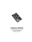
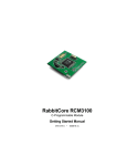
The RCM2000 series modules have two 40-pin headers to which cables can be connected,
or which can be plugged into matching sockets on a production device. The pinouts for
these connectors are shown in Figure 1 below.
J2
A12
A10
A8
A6
A4
A2
A0
PC0
PC2
PC4
PC6
PD0
PD2
PD4
PD6
GND
VBAT
SMODE0
/RES_OUT
VCC
J1
A11
A9
A7
A5
A3
A1
STATUS
PC1
PC3
PC5
PC7
PD1
PD3
PD5
PD7
VCC
VRAM
SMODE1
/RES_IN
GND
GND
PA0
PA2
PA4
PA6
PB0
PB2
PB4
PB6
PCLK
D7
D5
D3
D1
PE7
PE5
PE3
PE1
/IOWR
/BUFEN
VCC
PA1
PA3
PA5
PA7
PB1
PB3
PB5
PB7
GND
D6
D4
D2
D0
PE6
PE4
PE2
PE0
/IORD
/WDO
Note: These are the pinouts as seen on the
Bottom Side of the RCM2000.
Figure 1. RCM2000 Connector Pinout
2
Downloaded from Elcodis.com electronic components distributor
RabbitCore RCM2000
1.3 Development Software
The RCM2000 series of modules uses the Dynamic C development environment for rapid
creation and debugging of runtime applications. Dynamic C provides a complete development environment with integrated editor, compiler and source-level debugger. It interfaces
directly with the target system, eliminating the need for complex and unreliable in-circuit
emulators.
Dynamic C must be installed on a Windows workstation with at least one free serial
(COM) port for communication with the target system. See Chapter 3., “Installing
Dynamic C,” for complete information on installing Dynamic C.
Getting Started
Downloaded from Elcodis.com electronic components distributor
3
1.4 How to Use This Manual
This Getting Started manual is intended to give users a quick but solid start with the
RCM2000 series modules. It does not contain detailed information on the module hardware capabilities or the Dynamic C development environment. Most users will want more
detailed information on some or all of these topics in order to put the RCM2000 to effective use.
1.4.1 Additional Product Information
Detailed information about the RabbitCore RCM2100 series is provided in the RabbitCore RCM2000 User’s Manual, which is available on the accompanying CD-ROM in
both HTML and Adobe PDF format.
Some advanced users may choose to skip the rest of this introductory manual and proceed
directly with the detailed hardware and software information in the User’s Manual.
TIP: We recommend that anyone not thoroughly familiar with Z-World controllers at
least read through the rest of this manual to gain the necessary familiarity to make use
of the more advanced information.
1.4.2 Additional Reference Information
In addition to the product-specific information contained in the RabbitCore RCM2000
User’s Manual, several higher level reference manuals are provided in HTML and PDF
form on the accompanying CD-ROM. Advanced users will find these references valuable
in developing systems based on the RCM2100 series modules:
• Dynamic C User’s Manual
• Rabbit 2000 Microprocessor User’s Manual
4
Downloaded from Elcodis.com electronic components distributor
RabbitCore RCM2000
1.4.3 Using Online Documentation
We provide the bulk of our user and reference documentation in two electronic formats,
HTML and Adobe PDF. We do this for several reasons.
We believe that providing all users with our complete library of product and reference
manuals is a useful convenience. However, printed manuals are expensive to print, stock,
and ship. Rather than include and charge for manuals that every user may not want, or provide only product-specific manuals, we chose to provide our complete documentation and
reference library in electronic form with every Development Kit and with our Dynamic C
development environment.
Finding Online Documents
The online documentation is installed along with Dynamic C, and an icon for the documentation menu is placed on the workstation’s desktop. Double-click this icon to reach the
menu. If the icon is missing, create a new desktop icon that points to default.htm in the
docs folder, found in the Dynamic C installation folder.
The latest versions of all documents are always available for free, unregistered download
from our Web sites as well.
Printing Electronic Manuals
We recognize that many users prefer printed manuals for some uses. Users can easily print
all or parts of those manuals provided in electronic form. The following guidelines may be
helpful:
• Print from the Adobe PDF versions of the files, not the HTML versions.
NOTE: The most current version of Adobe Acrobat Reader can always be downloaded
from Adobe’s web site at http://www.adobe.com. We recommend that you use version 4.0 or later.
• Print only the sections you will need to refer to often.
• Print manuals overnight, when appropriate, to keep from tying up shared resources during the work day.
• If your printer supports duplex printing, print pages double-sided to save paper and
increase convenience.
NOTE: If you do not have a suitable printer or do not want to print the manual yourself,
most retail copy shops (e.g., Kinkos, AlphaGraphics, etc.) will print the manual from the
PDF file and bind it for a reasonable charge—about what we would have to charge for a
printed and bound manual.
Getting Started
Downloaded from Elcodis.com electronic components distributor
5
6
Downloaded from Elcodis.com electronic components distributor
RabbitCore RCM2000
2. HARDWARE SETUP
This chapter describes the RCM2000 hardware in more detail,
and explains how to set up the accompanying Prototyping
Board.
NOTE: This chapter (and this manual) assume that you have the RabbitCore RCM2000
Development Kit. If you purchased an RCM2000 series module by itself, you will have
to adapt the information in this chapter and elsewhere to your test and development
setup.
2.1 Development Kit Contents
The RCM2000 series Development Kit contains the following items:
• RCM2020 module with 256K flash memory and 128K SRAM.
• RCM2000 Prototyping Board with accessory hardware and components.
• Wall transformer power supply, 12 V DC, 500 mA (included only with Development
Kits sold for the North American market. Overseas users will need a power supply
compatible with their local mains power).
• 10-pin header to DE9 programming cable with integrated level-matching circuitry.
• Dynamic C CD-ROM, with complete product documentation on disk.
• This Getting Started manual.
• Registration card.
Getting Started
Downloaded from Elcodis.com electronic components distributor
7
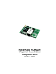
2.2 Overview of the Prototyping Board
The Prototyping Board included in the Development Kit makes it easy to connect an
RCM2000 module to a power supply and a PC workstation for development. It also provides an array of basic I/O peripherals (switches and LEDs), as well as a prototyping area
for more advanced hardware development.
For the most basic level of evaluation and development, the Prototyping Board can be
used without modification.
As you progress to more sophisticated experimentation and hardware development, modifications and additions can be made to the board without modifying or damaging the
RCM2000 itself.
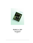
The Prototyping Board is shown in Figure 2 below, with its main features identified.
Voltage Power
Regulator Input
RCM2000
Connectors
Power
LED
J5
S3
RXC TXC
GND
C5
PC5
PC7
PD1
PD3
PD5
PD7
PC6
PD0
PD2
PD4
PD6
GND
PC3
PC4
VCC
PC1
PC2
/RSTI
STAT
PC0
SM1
A1
A0
VRAM
A3
A2
/RSTO
A5
A4
VCC
A7
A6
SM0
A9
A8
GND
A11
A10
User
LEDs
RXB
TXB
C6
VBAT
C4
A12
/IOR
PE0
PE2
PE4
PE6
D0
D2
D4
D6
GND
PB7
PB5
PB3
PB1
PA7
PA5
J6
RS-232
C3
/WDO
/BEN
/IOW
PE1
PE3
PE5
PE7
D1
D3
D5
D7
PCLK
PB6
PB4
PB2
PA6
PA4
PB0
S2
PB3
U2
PA3
S3
PB2
Reset
Switch
DS3
S2 DS3
PA1
C2
PA1
DS1
DS2
PA0
+
C1
J4
S1
JP1DS2
U1
PA2
GND
J2
D2
PA0
VCC
RCM2000 PROTOTYPING BOARD
PWR
RESET
RN1
J3
J1
RS-232
Area
VCC
GND
RCM2000
Extension Headers
GND
Through-Hole
Prototyping Area
Vcc and GND
Buses
SMT Prototyping
Area
Figure 2. RCM2000 Prototyping Board
8
Downloaded from Elcodis.com electronic components distributor
RabbitCore RCM2000
2.3 Connections
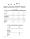
1. Attach RCM2000 to Prototyping Board
Turn the RCM2000 so that the Rabbit 2000 microprocessor is facing as shown below. Plug
RCM2000 Headers J1 and J2 into the sockets of headers J1 and J3 on the Prototyping Board.
RCM2000
Module
TP1
/WDO
GND Y1
PA0
PA2 C1
PA4
U1
PA6
PB0
PB2
PB4
PB6
PCLK
D7
D5
D3
D1
PE7
PE5
PE3
C7
PE1
/IOW
/BEN
TP3
TP2
R1
R2
C2
U2
JP3
J2
JP1
SRAM
R4 R6 U5
A11
A9
A7
A5
A3
A1
STAT
PC1
PC3
PC5
PC7
PD1
PD3
PD5
PD7
VCC
VRAM
SM1
A12
A10
A8
A6
A4
A2
A0
PC0
PC2
PC4
PC6
PD0
PD2
PD4
PD6
GND
VBAT
SM0
/RSTI
/RESO
GND
VCC
D3
R11
Prototyping
Board
J1
R8
VCC
PA1
PA3
PA5
PA7
PB1
PB3
PB5
PB7
GND
D6
D4
D2
D0
PE6
PE4
PE2
PE0
/IOR
C8 C9 R7D2
TP4
J3
Line up the
mounting holes
J5
PB2
PA1
S2
PB3
S3
VRAM
SM1
/RSTI
GND
VCC
PD5
/RSTO
PD3
PD4
VCC
PD1
PD2
SM0
PC7
PD0
PD6
PC5
GND
PC3
PC6
VBAT
PC1
A1
A2
PC4
A3
A4
STAT
A5
A6
RXB
TXB
C6
PC2
A7
A8
C5
PD7
C4
GND
RXC TXC
RS-232
A0
A9
A10
J6
PC0
A11
A12
/IOR
PE0
PE2
PE4
PE6
D0
D2
D4
D6
GND
PB7
PB5
PB3
PB1
PA7
PA5
DS3
S3
PA0
+
C1
C3
/WDO
/BEN
/IOW
PE1
PE3
PE5
PE7
D1
D3
D5
D7
PCLK
PB6
PB4
PB2
PA6
PA4
PB0
PA3
PA1
DS1
DS2
S2 DS3
U1
U2
J4
S1
JP1DS2
C2
PA2
GND
J2
D2
PA0
VCC
RCM2000 PROTOTYPING BOARD
PWR
RESET
RN1
J3
J1
VCC
GND
GND
Figure 3. Attaching RCM2000 to Prototyping Board
NOTE: It is important that you line up the pins on the RCM2000 headers J1 and J2
exactly with the corresponding pins of headers J1 and J3 on the Prototyping Board. The
header pins may become bent or damaged if the pin alignment is offset, and the
RCM2000 will not work.
Getting Started
Downloaded from Elcodis.com electronic components distributor
9
2. Connect RCM2000 to PC
Connect the 10-pin connector of the programming cable labeled PROG to header J3 on the
RCM2000 module as shown in Figure 4 below. Be sure to orient the red edge of the cable
towards pin 1 of the connector. (Do not use the DIAG connector, which is used for a normal
serial connection.)
The holes shown near
J1 and J2 at the top of
the RCM2000 exist to
align the board for factory
testing. Do not use these
holes for mounting.
NOTE:
RCM2000
Module
TP1
PA0
+
C1
PB2
RESET
S2
S3
J6
RS-232
C5
RXB
TXB
PC3
PC5
PC7
PD1
PD3
PD5
PD7
PC6
PD0
PD2
PD4
PD6
GND
PC1
PC4
VCC
STAT
PC2
/RSTI
A1
PC0
SM1
A3
A0
VRAM
A5
A2
/RSTO
A7
A4
VCC
A9
C6
SM0
C4
GND
RXC TXC
C2
U2
PROG
Colored side
lines up with
pin 1
DS3
PB3
A6
J4
RESET
SWITCH
S3
PA1
GND
VCC
DS1
DS2
A11
/IOR
PE0
GND
S1
JP1DS2
U1
C3
/WDO
/BEN
PE2
PE4
PE6
/RESO
D2
J3
/IOW
PE1
PE3
D0
D2
D4
D6
TP4
PE5
PE7
D1
D3
GND
C8 C9 R7D2
D5
PB7
D3
/RSTI
PWR
VBAT
R4 R6 U5
RN1
S2 DS3
SRAM
A12
A10
A8
A6
A4
A2
A0
PC0
PC2
PC4
PC6
PD0
PD2
PD4
PD6
GND
VBAT
SM0
A8
U2
JP3
J5
J2
A9
A7
A5
A3
A1
STAT
PC1
PC3
PC5
PC7
PD1
PD3
PD5
PD7
VCC
VRAM
SM1
A10
C2
J3A11
JP1
A12
R2
D7
PB5
R1
PCLK
PB3
PB1
PA7
PA5
TP3
TP2
PB6
PB4
PB2
PA6
PA4
U1
PB0
PA1
VCC
PA3
PA2
PA0
GND
/WDO
Y1
GND
PA0
PA2 C1
PA4
PA6
PB0
PB2
PB4
PB6
PCLK
D7
D5
D3
D1
PE7
PE5
PE3
C7
PE1
/IOW
/BEN
R11
J2
J1
PA1
PA3
PA5
PA7
PB1
PB3
PB5
PB7
GND
D6
D4
D2
D0
PE6
PE4
PE2
PE0
/IOR
R8
RCM2000 PROTOTYPING BOARD
VCC
J1
Prototyping
Board
DIAG
To
PC COM port
Figure 4. RCM2000 Power and Programming Connections
3. Power Supply Connections
Hook up the connector from the wall transformer to header J5 on the Prototyping Board as
shown above. The orientation of this connector is not important since the VIN (positive)
voltage is the middle pin, and GND is available on both ends of the three-pin header J5.
Plug in the wall transformer. The power LED on the Prototyping Board should light up.
The RCM2000 and the Prototyping Board are now ready to be used.
NOTE: A RESET button is provided on the Prototyping Board to allow a hardware reset.
10
Downloaded from Elcodis.com electronic components distributor
RabbitCore RCM2000
2.4 Where Do I Go From Here?
We recommend that you proceed to the next chapter and install Dynamic C (if you do not
already have it installed), then run the first sample program to verify that the RCM2000
and the Prototyping Board are set up and functioning correctly.
If everything appears to be working, we recommend the following sequence of action:
1. Run all of the sample programs described in Chapter 4 to get a basic familiarity with
Dynamic C and the RCM2000’s capabilities.
2. For further development, refer to the RabbitCore RCM2000 User’s Manual for details
of the module’s hardware and software components.
A documentation icon should have been installed on your workstation’s desktop; click
on it to reach the documentation menu. You can create a new desktop icon that points to
default.htm in the docs folder in the Dynamic C installation folder.
3. For advanced development topics, refer to the Dynamic C User’s Manual, also in the
online documentation set.
2.4.1 Technical Support
NOTE: If you purchased your RCM2000 through a distributor or through a Z-World or
Rabbit Semiconductor partner, contact the distributor or partner first for technical support.
If there are any problems at this point:
• Check the Z-World/Rabbit Semiconductor Technical Bulletin Board at
www.zworld.com/support/bb/.
• Use the Technical Support e-mail form at www.zworld.com/support/support_submit.html.
Getting Started
Downloaded from Elcodis.com electronic components distributor
11
12
Downloaded from Elcodis.com electronic components distributor
RabbitCore RCM2000
3. INSTALLING DYNAMIC C
To develop and debug programs for the RCM2000 series (and
for all other Z-World and Rabbit Semiconductor hardware), you
must install and use Dynamic C. This chapter takes you through
the installation of Dynamic C, and then provides a tour of its
major features with respect to the RCM2000 series.
3.1 An Overview of Dynamic C
Dynamic C integrates the following development functions into one program:
• Editing
• Compiling
• Linking
• Loading
• Debugging
In fact, compiling, linking and loading are one function. Dynamic C does not use an InCircuit Emulator; programs being developed are downloaded to and executed from the
“target” system via an enhanced serial-port connection. Program development and debugging take place seamlessly across this connection, greatly speeding system development.
Other features of Dynamic C include:
• Dynamic C has an easy-to-use built-in text editor. Programs can be executed and
debugged interactively at the source-code or machine-code level. Pull-down menus and
keyboard shortcuts for most commands make Dynamic C easy to use.
• Dynamic C also supports assembly language programming. It is not necessary to leave
C or the development system to write assembly language code. C and assembly language may be mixed together.
• Debugging under Dynamic C includes the ability to use printf commands, watch
expressions, breakpoints and other advanced debugging features. Watch expressions
can be used to compute C expressions involving the target’s program variables or functions. Watch expressions can be evaluated while stopped at a breakpoint or while the
target is running its program.
Getting Started
Downloaded from Elcodis.com electronic components distributor
13
• Dynamic C provides extensions to the C language (such as shared and protected variables, costatements and cofunctions) that support real-world embedded system development. Interrupt service routines may be written in C. Dynamic C supports
cooperative and preemptive multi-tasking.
• Dynamic C comes with many function libraries, all in source code. These libraries support real-time programming, machine level I/O, and provide standard string and math
functions.
• Dynamic C compiles directly to memory. Functions and libraries are compiled and
linked and downloaded on-the-fly. On a fast PC, Dynamic C can load 30,000 bytes of
code in 5 seconds at a baud rate of 115,200 bps.
3.2 System Requirements
To install and run Dynamic C, your system must be running one of the following operating
systems:
• Windows 95
• Windows 98
• Windows NT
• Windows Me
• Windows 2000
3.2.1 Hardware Requirements
The PC on which you install Dynamic C for development of RCM2000-based systems
should have the following hardware:
• A Pentium or later microprocessor
• 32 MB of RAM
• At least 40 MB of free hard drive space
• At least one free COM (serial) port for communication with the target systems
• A CD-ROM drive (for software installation)
14
Downloaded from Elcodis.com electronic components distributor
RabbitCore RCM2000
3.3 Installing Dynamic C
Insert the Dynamic C CD-ROM in the drive on your PC. If autorun is enabled, the CD
installation will begin automatically.
If autorun is disabled or the installation otherwise does not start, use the Windows
Start > Run menu or Windows Disk Explorer to launch SETUP.EXE from the root folder
of the CD-ROM.
The installation program will guide you through the installation process. Most steps of the
process are self-explanatory and not covered in this section. Selected steps that may be
confusing to some users are outlined below. (Some of the installation utility screens may
vary slightly from those shown.)
3.3.1 Program & Documentation File Location
Dynamic C’s application, library and documentation files can be installed in any convenient location on your workstation’s hard drives.
The default location, as shown in the example above, is in a folder named for the version
of Dynamic C, placed in the root folder of the C: drive. If this location is not suitable, enter
a different root path before clicking Next >. Files are placed in the specified folder, so do
not set this location to a drive’s root directory.
Getting Started
Downloaded from Elcodis.com electronic components distributor
15
3.3.2 Installation Type
Dynamic C has two components that can be installed together or separately. One component is Dynamic C itself, with the development environment, support files and libraries.
The other component is the documentation library in HTML and PDF formats, which may
be left uninstalled to save hard drive space or installed elsewhere (on a separate or network drive, for example).
The installation type is selected in the installation menu shown above. The options are:
• Typical Installation — Both Dynamic C and the documentation library will be installed
in the specified folder (default).
• Compact Installation — Only Dynamic C will be installed.
• Custom Installation — You will be allowed to choose which components are installed. This
choice is useful to install or reinstall just the documentation.
16
Downloaded from Elcodis.com electronic components distributor
RabbitCore RCM2000
3.3.3 Select COM Port
Dynamic C uses a COM (serial) port to communicate with the target development system.
The installation allows you to choose the COM port that will be used.
The default selection, as shown in the example above, is COM1. You may select any available port for Dynamic C’s use. If you are not certain which port is available, select COM1.
This selection can be changed later within Dynamic C.
NOTE: The installation utility does not check the selected COM port in any way. Specifying a port in use by another device (mouse, modem, etc.) may cause temporary problems when Dynamic C is started.
3.3.4 Desktop Icons
Once your installation is complete, you will have up to three icons on your PC desktop, as
shown below.
One icon is for Dynamic C, one opens the documentation menu, and the third is for the
Rabbit Field Utility, a tool used to download precompiled software to a target system.
Getting Started
Downloaded from Elcodis.com electronic components distributor
17
3.4 Starting Dynamic C
Once the RCM2000 module is set up and connected as described in Chapter 2 and
Dynamic C has been installed, start Dynamic C by double-clicking on the Dynamic C
icon. Dynamic C should start, then look for the target system on the COM port you specified during installation (by default, COM1). Once detected, Dynamic C should go through
a sequence of steps to cold-boot the module and compile the BIOS.
If you receive the message beginning “BIOS successfully compiled …” you are ready to
continue with the sample programs in the next chapter.
3.4.1 Communication Error Messages
If you receive the message “No Rabbit Processor Detected,” the programming cable may
be connected to a different COM port, a connection may be faulty, or the target system
may not be powered up. First, check to see that the power LED on the Prototyping Board
is lit. If it is, check both ends of the programming cable to ensure that it is firmly plugged
into the PC and the RCM2000’s programming port. If you are using the Prototyping
Board, ensure that the module is firmly and correctly installed in its connectors.
If there are no faults with the hardware, select a different COM port within Dynamic C.
From the Options menu, select Project Options, then select Communications. The
dialog shown should appear.
Select another COM port from the list, then click OK. Press <Ctrl-Y> to force Dynamic C to recompile the BIOS. If Dynamic C still reports it is unable to locate the target system, repeat the above
steps until you locate the active COM port.
If Dynamic C appears to compile the BIOS successfully, but you then receive a communication error message, it is possible that your PC cannot handle the 115,200 bps baud rate.
Try changing the baud rate to 57,600 bps as follows.
• Locate the Serial Options dialog in the Dynamic C Options > Project Options >
Communications menu. Change the baud rate to 57,600 bps.
18
Downloaded from Elcodis.com electronic components distributor
RabbitCore RCM2000
If you are using Dynamic C version 7.04 or earlier, modify the BIOS source code as follows. Skip these three steps if your version of Dynamic C is 7.05 or later.
1. Open the BIOS source code file named RABBITBIOS.C, which can be found in the
BIOS directory.
2. Change the line
#define USE115KBAUD 1
// set to 0 to use 57600 baud
to read as follows.
#define USE115KBAUD 0
// set to 0 to use 57600 baud
3. Save the changes using File > Save.
Now press <Ctrl-Y>. You should receive the “BIOS successfully compiled …” message
indicating that the target is now ready to compile a program. You should then continue with
the sample programs in the next chapter.
Getting Started
Downloaded from Elcodis.com electronic components distributor
19
20
Downloaded from Elcodis.com electronic components distributor
RabbitCore RCM2000
4. SAMPLE PROGRAMS
To help familiarize you with the RCM2000 modules, several
sample Dynamic C programs have been included. Loading, executing and studying these programs will give you a solid handson overview of the RCM2000’s capabilities, as well as a quick
start with Dynamic C as an application development tool.
4.1 Sample Program Overview
Dynamic C comes with a large number of sample programs that illustrate many of its features. These programs are intended to serve as tutorials, but then can also be used as starting points or building blocks for your own applications.
NOTE: It is assumed in this section that you have at least an elementary grasp of ANSI C.
If you do not, see the introductory pages of the Dynamic C User’s Manual for a suggested reading list.
Sample programs are provided in the Dynamic C Samples folder, which is shown below.
Getting Started
Downloaded from Elcodis.com electronic components distributor
21
The various folders contain specific sample programs that illustrate the use of the corresponding Dynamic C libraries. The sample program PONG.c demonstrates the output to
the STDIO window. The COREMODULE folder provides sample programs specific to the
RCM2000. Let’s take a look at the COREMODULE folder.
Each sample program has comments that describe the purpose and function of the program.
Before running any of these sample program, make sure that your RCM2000 is connected
to the Prototyping Board and to your PC as described in Section 2.3, “Connections.”
22
Downloaded from Elcodis.com electronic components distributor
RabbitCore RCM2000
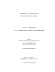
4.2 Running Sample Program FLASHLED.C
This sample program will be used to illustrate some of the functions of Dynamic C.
First, open the file FLASHLED.C, which is in the Samples/COREMODULE folder. The program will appear in a window, as shown in Figure 5 below (minus some comments). Use
the mouse to place the cursor on the function name WrPortI in the program and type
<Ctrl-H>. This will bring up a documentation box for the function WrPortI. In general,
you can do this with all functions in Dynamic C libraries, including libraries you write
yourself. Close the documentation box and continue.
C programs begin with main
Set up Port A to output
to LED DS2 and DS3
main(){
int j;
WrPortI(SPCR,&SPCRShadow,0x84);
WrPortI(PADR,&PADRShadow,0xFF);
Start a loop
Turn LED DS3 off
while(1) {
BitWrPortI(PADR,&PADRShadow,1,1);
for(j=0; j<32000; j++);
Time delay by counting
to 32,000
BitWrPortI(PADR,&PADRShadow,0,1);
Turn LED DS3 on
for(j=0; j<25000; j++);
} // end while
} //
end of main
Time delay by counting
to 25,000
End of the endless loop
Note: See the Rabbit 2000 Microprocessor User’s Manual
(Software Chapter) for details on the routines that read and
write I/O ports.
Figure 5. Sample Program FLASHLED.C
To run the program FLASHLED.C, load it with the File menu, compile it using the Compile menu, and then run it by selecting Run in the Run menu. The LED on the Prototyping
Board should start flashing if everything went well. If this doesn’t work review the following points.
• The target should be ready, which is indicated by the message “BIOS successfully compiled...” If you did not receive this message or you get a communication error, recompile the BIOS by typing <Ctrl-Y> or select Recompile BIOS from the Compile menu.
Getting Started
Downloaded from Elcodis.com electronic components distributor
23
• A message reports “No Rabbit Processor Detected” in cases where the RCM2000 and
the Prototyping Board are not connected together, the wall transformer is not connected, or is not plugged in. (The red power LED lights whenever power is connected.)
• The programming cable must be connected to the RCM2000. (The colored wire on the
programming cable is closest to pin 1 on header J3 on the RCM2000, as shown in
Figure 4.) The other end of the programming cable must be connected to the PC serial
port. The COM port specified in the Dynamic C Options menu must be the same as the
one the programming cable is connected to.
• To check if you have the correct serial port, select Compile, then Compile BIOS, or
type <Ctrl-Y>. If the “BIOS successfully compiled …” message does not display, try a
different serial port using the Dynamic C Options menu until you find the serial port
you are plugged into. Don’t change anything in this menu except the COM number.
The baud rate should be 115,200 bps and the stop bits should be 1.
4.3 Single-Stepping
Compile or re-compile FLASHLED.C by clicking the Compile button on the task bar. The
program will compile and the screen will come up with a highlighted character (green) at
the first executable statement of the program. Use the F8 key to single-step. Each time the
F8 key is pressed, the cursor will advance one statement. When you get to the for(j=0,
j< ... statement, it becomes impractical to single-step further because you would have
to press F8 thousands of times. We will use this statement to illustrate watch expressions.
4.3.1 Watch Expressions
Type <Ctrl-W> or chose Add/Del Watch Expression in the Inspect menu. A box will
come up. Type the lower case letter j and click on add to top and close. Now continue single-stepping with F8. Each time you step, the watch expression (j) will be evaluated and
printed in the watch window. Note how the value of j advances when the statement j++ is
executed.
4.3.2 Break Point
Move the cursor to the start of the statement:
for(j=0; j<25000; j++);
To set a break point on this statement, type F2 or select Toggle Breakpoint from the Run
menu. A red highlight will appear on the first character of the statement. To get the program running at full speed, type F9 or select Run on the Run menu. The program will
advance until it hits the break point. Then the break point will start flashing and show both
red and green colors. Note that LED DS3 is now solidly turned on. This is because we
have passed the statement turning on LED DS3. Note that j in the watch window has the
value 32000. This is because the loop above terminated when j reached 32000.
To remove the break point, type F2 or select Toggle Breakpoint on the Run menu. To
continue program execution, type F9 or select Run from the Run menu. Now the LED
should be flashing again since the program is running at full speed.
24
Downloaded from Elcodis.com electronic components distributor
RabbitCore RCM2000
You can set break points while the program is running by positioning the cursor to a statement and using the F2 key. If the execution thread hits the break point, a break point will
take place.You can toggle the break point off with the F2 key and continue execution with
the F9 key. Try this a few times to get the feel of things.
4.3.3 Editing the Program
Click on the Edit box on the task bar. This will set Dynamic C into the edit mode so that
you can change the program. Use the Save as choice on the File menu to save the file
with a new name so as not to change the demo program. Save the file as MYTEST.C. Now
change the number 25000 in the for (.. statement to 10000. Then use the F9 key to
recompile and run the program. The LED will start flashing, but it will flash much faster
than before because you have changed the loop counter terminal value from 25000 to
10000.
4.3.4 Watching Variables Dynamically
Go back to edit mode (select edit) and load the program FLASHLED2.C using the File
menu Open command. This program is the same as the first program, except that a variable k has been added along with a statement to increment k each time around the endless
loop. The statement:
runwatch();
has been added. This is a debugging statement that makes it possible to view variables
while the program is running.
Use the F9 key to compile and run FLASHLED2.C. Now type <Ctrl-W> to open the watch
window and add the watch expression k to the top of the list of watch expressions. Now
type <Ctrl-U>. Each time you type <Ctrl-U>, you will see the current value of k, which is
incrementing about 5 times a second.
As an experiment, add another expression to the watch window:
k*5
Then type <ctrl-U> several times to observe the watch expressions k and k*5.
4.3.5 Summary of Features
So far you have practiced using the following features of Dynamic C.
• Loading, compiling and running a program. When you load a program it appears in an
edit window. You can compile by selecting Compile on the task bar or from the Compile menu. When you compile the program, it is compiled into machine language and
downloaded to the target over the serial port. The execution proceeds to the first statement of main where it pauses, waiting for you to command the program to run, which
you can do with the F9 key or by selecting Run on the Run menu. If want to compile
and start the program running with one keystroke, use F9, the run command. If the program is not already compiled, the run command will compile it first.
• Single-stepping. This is done with the F8 key. The F7 key can also be used for singlestepping. If the F7 key is used, then descent into subroutines will take place. With the
Getting Started
Downloaded from Elcodis.com electronic components distributor
25
F8 key the subroutine is executed at full speed when the statement that calls it is
stepped over.
• Setting break points. The F2 key is used to turn on or turn off (toggle) a break point at
the cursor position if the program has already been compiled. You can set a break point
if the program is paused at a break point. You can also set a break point in a program
that is running at full speed. This will cause the program to break if the execution
thread hits your break point.
• Watch expressions. A watch expression is a C expression that is evaluated on command
in the watch window. An expression is basically any type of C formula that can include
operators, variables and function calls, but not statements that require multiple lines
such as for or switch. You can have a list of watch expressions in the watch window. If
you are single-stepping, then they are all evaluated on each step. You can also command the watch expression to be evaluated by using the <Ctrl-U> command. When a
watch expression is evaluated at a break point, it is evaluated as if the statement was at
the beginning of the function where you are single-stepping. If your program is running
you can also evaluate watch expressions with a <Ctrl-U> if your program has a
runwatch() command that is frequently executed. In this case, only expressions
involving global variables can be evaluated, and the expression is evaluated as if it
were in a separate function with no local variables.
4.4 Cooperative Multitasking
Cooperative multitasking is a convenient way to perform several different tasks at the
same time. An example would be to step a machine through a sequence of steps and at the
same time independently carry on a dialog with the operator via a human interface. Cooperative multitasking differs from another approach called preemptive multitasking.
Dynamic C supports both types of multitasking. In cooperative multitasking each separate
task voluntarily surrenders its compute time when it does not need to perform any more
activity immediately. In preemptive multitasking control is forcibly removed from the task
via an interrupt.
Dynamic C has language extensions to support multitasking. The major C constructs are
called costatements, cofunctions, and slicing. These are described more completely in the
Dynamic C User’s Manual. The example below, sample program FLASHLEDS2.C, uses
costatements. A costatement is a way to perform a sequence of operations that involve
pauses or waits for some external event to take place. A complete description of costatements is in the Dynamic C User’s Manual. The FLASHLEDS2.C sample program has two
independent tasks. The first task flashes LED DS2 2.5 times a second. The second task
flashes DS3 every 1.5 seconds.
26
Downloaded from Elcodis.com electronic components distributor
RabbitCore RCM2000
#define DS2 0
#define DS3 1
// predefine for LED DS2
// predefine for LED DS3
// This cofunction flashes LED on for ontime, then off
cofunc flashled[4](int led, int ontime, int offtime) {
for(;;) {
waitfor(DelayMs(ontime));
WrPortI(PADR,&PADRShadow,(1<<led)|PADR);
waitfor(DelayMs(offtime);
WrPortI(PADR,&PADRShadow,(1<<led)^0xff&PADR);
}
}
main {
// Initialize ports
WrPortI(SPCR,&SPCRShadow,0x84);
WrPortI(PEFR,&PEFRShadow,0x00);
WrPortI(PEDDR,&PEDDRShadow,0x01);
WrPortI(PECR,&PECRShadow,0x00);
}
//
//
//
//
Set
Set
Set
Set
for offtime
//
//
//
//
on delay
turn LED off
off delay
turn LED on
Port A all outputs, LEDs on
Port E normal I/O
Port E bits 7…1 input, 0 output
transfer clock as pclk/2
for(;;) {
// run forever
costate {
// start costatement
wfd {
// use wfd (waitfordone) with cofunctions
flashled[0](DS2,200,200); // flash DS2 on 200 ms, off 200 ms
flashled[1](DS3,1000,500);// flash DS3 on 1000 ms, off 500 ms
}
}
// end costatement
}
// end for loop
// end of main, never come here
Load and run the program.
The flashing of the LEDs is performed by the costatement. Costatements need to be executed regularly, often at least every 25 ms. To accomplish this, the costatements are
enclosed in a while loop or a for loop. The term while loop is used as a handy way to
describe a style of real-time programming in which most operations are done in one loop.
The costatement is executed on each pass through the big loop. When a waitfor or a wfd
condition is encountered the first time, the current value of MS_TIMER is saved and then
on each subsequent pass the saved value is compared to the current value. If a waitfor
condition is not encountered, then a jump is made to the end of the costatement, and on the
next pass of the loop, when the execution thread reaches the beginning of the costatement,
execution passes directly to the waitfor statement. The costatement has the property that
it can wait for long periods of time, but not use a lot of execution time. Each costatement
is a little program with its own statement pointer that advances in response to conditions.
On each pass through the big loop, as little as one statement in the costatement is executed, starting at the current position of the costatement’s statement pointer. Consult the
Dynamic C User’s Manual for more details.
This program also illustrates a use for a shadow register. A shadow register is used to keep
track of the contents of an I/O port that is write only—it can’t be read back. If every time a
write is made to the port the same bits are set in the shadow register, then the shadow register has the same data as the port register.
Getting Started
Downloaded from Elcodis.com electronic components distributor
27
4.5 Advantages of Cooperative Multitasking
Cooperative multitasking, as implemented with language extensions, has the advantage of
being intuitive. Unlike preemptive multitasking, variables can be shared between different
tasks without having to take elaborate precautions. Sharing variables between tasks is the
greatest cause of bugs in programs that use preemptive multitasking. It might seem that
the biggest problem would be response time because of the big loop time becoming long
as the program grows. Our solution for that is called slicing, which is further described in
the Dynamic C User’s Manual.
28
Downloaded from Elcodis.com electronic components distributor
RabbitCore RCM2000
NOTICE TO USERS
Z-WORLD PRODUCTS ARE NOT AUTHORIZED FOR USE AS CRITICAL COMPONENTS IN LIFESUPPORT DEVICES OR SYSTEMS UNLESS A SPECIFIC WRITTEN AGREEMENT REGARDING
SUCH INTENDED USE IS ENTERED INTO BETWEEN THE CUSTOMER AND Z-WORLD PRIOR
TO USE. Life-support devices or systems are devices or systems intended for surgical implantation into the
body or to sustain life, and whose failure to perform, when properly used in accordance with instructions for
use provided in the labeling and user’s manual, can be reasonably expected to result in significant injury.
No complex software or hardware system is perfect. Bugs are always present in a system of any size. In
order to prevent danger to life or property, it is the responsibility of the system designer to incorporate
redundant protective mechanisms appropriate to the risk involved.
All Z-World products are 100 percent functionally tested. Additional testing may include visual quality control inspections or mechanical defects analyzer inspections. Specifications are based on characterization of
tested sample units rather than testing over temperature and voltage of each unit. Z-World products may
qualify components to operate within a range of parameters that is different from the manufacturer’s recommended range. This strategy is believed to be more economical and effective. Additional testing or burn-in
of an individual unit is available by special arrangement.
Getting Started
Downloaded from Elcodis.com electronic components distributor
29
30
Downloaded from Elcodis.com electronic components distributor
RabbitCore RCM2000
INDEX
A
H
additional information
online documentation .......... 5
references ............................ 4
C language ............................ 13
hardware connections ............. 9
install RCM2000 on Prototyping Board ........................ 9
power supply ..................... 10
programming cable ........... 10
hardware reset ....................... 10
D
I
description ............................... 1
Development Kit ..................... 7
Dynamic C .................. 3, 13, 14
assembly language ............ 13
changing programming baud
rate in BIOS .................. 18
debugger ............................ 13
debugging .......................... 13
desktop icons ..................... 17
editor ................................. 13
features ........................ 13, 25
handling communication error
messages ....................... 18
hardware requirements ...... 14
installing ................ 15, 16, 17
interrupt service routines .. 14
multitasking ...................... 26
sample programs ............... 21
break point ..................... 24
editing a program .......... 25
single-stepping .............. 24
watch expressions ......... 24
starting .............................. 18
watch expressions ............. 13
interrupt service routines ...... 14
C
F
features
Prototyping Board ............... 8
RCM2000 ............................ 1
M
models
factory versions ................... 1
P
pinout
RCM2000 ............................ 2
power supply
connections ....................... 10
programming cable
RCM2000 connections ..... 10
Prototyping Board ................... 8
features ................................ 8
mounting RCM2000 ........... 9
R
RCM2000
mounting on Prototyping
Board .............................. 9
reset ....................................... 10
S
sample programs ................... 21
FLASHLED.C .................. 23
specifications
physical and electrical ......... 2
T
technical support ................... 11
User’s Manual
Downloaded from Elcodis.com electronic components distributor
31
User’s Manual
Downloaded from Elcodis.com electronic components distributor
32
SCHEMATICS
090-0097 RCM2000 Schematic
www.rabbitsemiconductor.com/documentation/schemat/090-0097.pdf
090-0099 RCM2000 Prototyping Board Schematic
www.rabbitsemiconductor.com/documentation/schemat/090-0099.pdf
090-0128 Programming Cable Schematic
www.rabbitsemiconductor.com/documentation/schemat/090-0128.pdf
The schematics included with the printed manual were the latest revisions available at the
time the manual was last revised. The online versions of the manual contain links to the
latest revised schematic on the Web site. You may also use the URL information provided
above to access the latest schematics directly.
Getting Started
Downloaded from Elcodis.com electronic components distributor
33
Downloaded from Elcodis.com electronic components distributor