1
PC Software
CMWIN
User manual
(Translation of original manual)
V03 R26 2011/08/24
HYDAC ELECTRONIC GMBH
Mat. No. 669844
PC-Software CMWIN V03
Page 2
TABLE OF CONTENTS
1
GENERAL INFORMATION ............................................................................................6
1.1
Previous Knowledge .................................................................................................6
1.2
Structure of the Manual ............................................................................................6
1.3
Copyright Protection.................................................................................................7
1.4
Note on Warranty.......................................................................................................7
2
SAFETY ..........................................................................................................................7
2.1
General Safety Precautions......................................................................................7
2.2
Proper/Designated Use .............................................................................................7
3
INSTALLATION..............................................................................................................8
3.1
Hardware and Software Requirements....................................................................8
3.2
Installing the USB-Driver ..........................................................................................8
3.3
Installing CMWIN .......................................................................................................8
3.4
Starting CMWIN .........................................................................................................8
4
DEFINITION OF TERMS ................................................................................................9
4.1
CM devices.................................................................................................................9
4.2
SMART Sensors.........................................................................................................9
5
USING CMWIN .............................................................................................................10
5.1
"File" Menu...............................................................................................................10
5.1.1
Open...................................................................................................................10
5.1.2
Import .................................................................................................................10
5.1.3
Save ...................................................................................................................10
5.1.4
Save As ..............................................................................................................10
5.1.5
Save All ..............................................................................................................10
5.1.6
Export .................................................................................................................11
5.1.7
Export Folder......................................................................................................12
5.1.8
Merge recordings ...............................................................................................13
5.1.9
Print ....................................................................................................................13
5.1.10 Close ..................................................................................................................13
5.1.11 Close All .............................................................................................................13
5.2
"View" Menu.............................................................................................................14
5.2.1
Graph .................................................................................................................14
5.2.2
Table ..................................................................................................................14
5.2.3
Recorded data....................................................................................................14
V03 R26 2011/08/24
HYDAC ELECTRONIC GMBH
Mat. No. 669844
PC-Software CMWIN V03
5.2.4
Page 3
Description .........................................................................................................14
5.3
"Graph" Menu ..........................................................................................................15
5.3.1
View....................................................................................................................15
5.3.2
Evaluation...........................................................................................................19
5.3.3
Other ..................................................................................................................21
5.4
"Edit" Menu ..............................................................................................................24
5.4.1
Extract Recording...............................................................................................24
5.4.2
Curve Overlay ....................................................................................................24
5.4.3
Time-Shift Channels...........................................................................................24
5.4.4
Add a Calculated Channel..................................................................................25
5.4.5
Add a filtered channel.........................................................................................25
5.4.6
Remove channels...............................................................................................26
5.5
"Units" Menu............................................................................................................27
5.5.1
Connection .........................................................................................................27
5.5.2
CM Manager.......................................................................................................30
5.6
"Extras" Menu..........................................................................................................32
5.6.1
CM Editor ...........................................................................................................32
5.6.2
Options ...............................................................................................................45
5.6.3
Reset options .....................................................................................................45
5.7
Help...........................................................................................................................45
APPENDIX A: CM PROGRAM FUNCTIONS ......................................................................46
A.1 General Information on Functions .............................................................................46
A.1.1 Inputs / Outputs .......................................................................................................46
A.1.2 Numerical Values ....................................................................................................46
A.1.3 Parameters..............................................................................................................47
A.2 Data Sources................................................................................................................48
A.2.1 Numerical Constants ...............................................................................................48
A.2.2 Measured Value ......................................................................................................48
A.2.3 Digital Input .............................................................................................................48
A.2.4 Numerical Entry.......................................................................................................49
A.2.5 Boolean Entry..........................................................................................................49
A.2.6 Timer .......................................................................................................................50
A.2.7 Clock Timer .............................................................................................................50
A.2.8 Error Event ..............................................................................................................51
A.2.9 Boolean Constants ..................................................................................................51
A.2.10 State-bit .................................................................................................................51
A.2.11 Sequence ..............................................................................................................52
A.2.12 Transition (in the field "Result values / Actions")...................................................52
A.3 Numerical Calculations ...............................................................................................53
A.3.1 Addition ...................................................................................................................53
A.3.2 Subtraction ..............................................................................................................53
A.3.3 Multiplication............................................................................................................53
A.3.4 Division....................................................................................................................53
A.3.5 Division Remainder .................................................................................................54
A.3.6 Absolute Value ........................................................................................................54
A.3.7 Change of Sign........................................................................................................54
V03 R26 2011/08/24
HYDAC ELECTRONIC GMBH
Mat. No. 669844
PC-Software CMWIN V03
Page 4
A.3.8 Rounding .................................................................................................................54
A.3.9 Raising to a Higher Power.......................................................................................55
A.3.10 Square Root ..........................................................................................................55
A.3.11 Power at Base e ....................................................................................................55
A.3.12 Natural Logarithm..................................................................................................55
A.3.13 Decade Logarithm .................................................................................................56
A.3.14 Integral ..................................................................................................................56
A.3.15 Differential Quotient...............................................................................................57
A.4 Numerical Operations .................................................................................................58
A.4.1 Minimum..................................................................................................................58
A.4.2 Maximum.................................................................................................................58
A.4.3 Limit.........................................................................................................................58
A.4.4 If - Then - Else.........................................................................................................58
A.4.5 Median Value ..........................................................................................................59
A.4.6 Extended Average...................................................................................................59
A.4.7 Note Value...............................................................................................................59
A.4.8 Note Minimum .........................................................................................................60
A.4.9 Note Maximum ........................................................................................................60
A.4.10 Tabular Value ........................................................................................................61
A.4.11 Tabular Index ........................................................................................................61
A.4.12 Characteristic curve...............................................................................................62
A.4.13 Slope .....................................................................................................................62
A.5 Counting Functions.....................................................................................................63
A.5.1 Count Pulses ...........................................................................................................63
A.5.2 Stop watch...............................................................................................................63
Numerical Conditions ........................................................................................................64
A.6.1 Equals .....................................................................................................................64
A.6.2 Does not Equal........................................................................................................64
A.6.3 Greater than ............................................................................................................65
A.6.4 Greater than or Equal to..........................................................................................65
A.6.5 Less than.................................................................................................................65
A.6.6 Less than or Equal to ..............................................................................................66
A.6.7 Within ......................................................................................................................66
A.6.8 Outside ....................................................................................................................66
A.7 Boolean Links ..............................................................................................................67
A.7.1 Not...........................................................................................................................67
A.7.2 And ..........................................................................................................................67
A.7.3 Not - And .................................................................................................................67
A.7.4 Or ............................................................................................................................68
A.7.5 Not - Or....................................................................................................................68
A.7.6 Exclusive Or ............................................................................................................69
A.7.7 Not Exclusive Or......................................................................................................69
A.8 Other Boolean Operations ..........................................................................................70
A.8.1 Note Switching Status .............................................................................................70
A.8.2 Switching Delay.......................................................................................................70
A.8.3 T - Flipflop ...............................................................................................................71
A.8.3 Mono Flop ...............................................................................................................71
A.8.4 RS - Flipflop.............................................................................................................72
A.8.5 Pulse Generation.....................................................................................................72
A.9 Result Values ...............................................................................................................73
V03 R26 2011/08/24
HYDAC ELECTRONIC GMBH
Mat. No. 669844
PC-Software CMWIN V03
Page 5
A.9.1 Numerical Output Value ..........................................................................................73
A.9.2 Boolean Output Value .............................................................................................74
A.10 Actions........................................................................................................................75
A.10.1 Setting Switching Output .......................................................................................75
A.10.2 Setting Analog Outputs .........................................................................................75
A.10.3 Display Message ...................................................................................................76
A.10.4 Switch on LED.......................................................................................................76
A.10.5 Compiling a Log Entry ...........................................................................................77
A.10.6 Compiling Quick Log Entries .................................................................................77
A.10.7 Start new log .........................................................................................................77
A.10.8 Transition (see Chap. A.2.12) ...............................................................................77
A.10.9 Send SMS .............................................................................................................78
A.11 Other ...........................................................................................................................78
A.11.1 Comment...............................................................................................................78
APPENDIX B: ERROR MESSAGES CM PROGRAM COMPILATION...............................79
B.1 Overriding Error Messages.........................................................................................80
B.1.1 Function not Available in this Mode.........................................................................80
B.2 Error Messages with Data Sources............................................................................80
B.2.1 Invalid Channel Setting ...........................................................................................80
B.2.2 Duplicate Channel Name ........................................................................................80
B.2.3 Invalid Digital Input ..................................................................................................80
B.2.4 Duplicate Digital Input .............................................................................................80
B.2.5 Too many Boolean Input Values .............................................................................80
B.2.6 No Inscription with Boolean Input............................................................................80
B.2.7 Duplicate Inscription with Boolean Inputs................................................................80
B.2.8 Too Many Numerical Input Values ..........................................................................80
B.2.9 No Inscription with Numerical Input.........................................................................81
B.2.10 Duplicate Inscription with Numerical Input ............................................................81
B.2.11 Duplicate Error Source ..........................................................................................81
B.3 Error Messages with Operations/Conditions............................................................81
B.3.1 Upper and Lower Measured Value Limits too Close to one another.......................81
B.3.2 Measured Value Limits Outside the Range of -30000 to 30000..............................81
B.3.3 Lower Measured Value Limit Greater than Upper Measurement Value Limit .........81
B.4 Error Messages with Result Values/Actions.............................................................81
B.4.1 Invalid Output LED Selected ...................................................................................81
5.7.2
B.4.2 Duplicate Usage of Output LED................................................................81
B.4.3 Invalid Digital Output ...............................................................................................82
B.4.4 Duplicate Digital Ouput............................................................................................82
B.4.5 Invalid Analog Output ..............................................................................................82
B.4.6 Duplicate Analog Output .........................................................................................82
B.4.7 Too Many Boolean Output Fields............................................................................82
B.4.8 Duplicate Boolean Output Field...............................................................................82
B.4.9 The Bit Number Must Be a Figure between 0 and 14 .............................................82
B.4.10 Too Many Numerical Output Fields.......................................................................82
B.4.11 Duplicate Numerical Output Field..........................................................................82
B.4.12 Message and Telephone Number too Long ..........................................................83
V03 R26 2011/08/24
HYDAC ELECTRONIC GMBH
Mat. No. 669844
PC-Software CMWIN V03
Page 6
1 General Information
This manual provides you with key information on the HYDAC CMWIN. It will show you
the most important screen dialogs and procedures. These are designed in such a way
that it is possible to start at almost any chapter.
Our “General Conditions of Sale and Delivery” and the “Special Conditions of Sale
and Delivery for Software Products / Freeware” apply to the use of the CMWIN.
These Terms and Conditions can be viewed on our website (click Company/Legal
information) or are available on request as a PDF file.
1.1 Previous Knowledge
No special previous knowledge is required for operating the CMWIN software. General
PC experience using Windows operating systems and Windows-based applications is
advantageous and will speed up the familiarization period.
1.2 Structure of the Manual
We have integrated a variety of different Help functions to make it easier to use this
manual. Please consult the Table of Contents to find a specific topic. A brief overview is
provided at the beginning of each Chapter listing the contents of that particular Chapter.
Selective Reading
You will find notes in the side margins that make it easier to find particular sections.
Pictograms and markings also appear, the significance of which will be explained
below.
Furthermore, this manual also contains instructions regarding personal safety and the
avoidance of property damage that must be observed. The instructions are highlighted
by a Warning symbol and displayed as follows, depending on the seriousness of the
hazard:
Caution
means that an unwanted event or condition could occur if the particular instruction is
not followed.
Note
means an important piece of information about the product, its handling or a part of the
documentation to which particular attention should be paid.
V03 R26 2011/08/24
HYDAC ELECTRONIC GMBH
Mat. No. 669844
PC-Software CMWIN V03
Page 7
1.3 Copyright Protection
The dissemination and/or reproduction of this document, as well as the exploitation and
communication of its content, is not permitted unless specifically authorized.
Contraventions are liable to compensation. All rights reserved.
1.4 Note on Warranty
This manual was compiled with the greatest possible care. Nevertheless, errors or
deviations cannot be excluded, for which reason we assume no responsibility for the
complete accuracy of the content.
In view of the fact that, despite intensive endeavors, errors can never be completely
avoided, we welcome tips and suggestions for improvement at any time.
2 Safety
2.1 General Safety Precautions
Follow the specifications contained in this description. Non-observance of the
instructions, operation in applications other than those outlined below, or incorrect
handling of the product can be severely detrimental to the safety of personnel and
systems/machines and will invalidate warranty and liability claims.
In the event of malfunction or uncertainty, please contact your HYDAC representative.
2.2 Proper/Designated Use
The PC software CMWIN can be used in conjunction with the following HYDAC
devices:
•
•
•
•
•
•
•
•
Portable data recorder HMG 3000
Portable data recorder HMG 510
Condition Monitoring Unit CMU 1000
Condition Sensor Interface CSI-F-10
Condition Sensor Interface CSI-B-2
Oil Condition Sensor HYDACLab®
AquaSensor AS 1000
Contamination Sensor CS 1000
The software has been developed for processing and evaluating measured data which
has been recorded using the above-mentioned HYDAC devices. We cannot accept any
liability or provide warranty outside this field of application.
V03 R26 2011/08/24
HYDAC ELECTRONIC GMBH
Mat. No. 669844
PC-Software CMWIN V03
Page 8
3 Installation
3.1 Hardware and Software Requirements
Minimum requirements:
Recommended:
PC, Pentium 400 MHz
256 MB RAM
Windows XP / 2000
CD-ROM drive
3 MB free hard disk space
RS 232 port
RS 232 connector cable
Graphics resolution: 640x480,
256 colors
PC, Pentium 1.8 GHz
256 MB RAM
Windows XP / 2000
CD-ROM drive
3 MB free hard disk space
USB 1.1
Graphics
resolution:
1024x768,
65536 colors
3.2 Installing the USB-Driver
If a HYDAC Measuring instrument (e.g. HMG 3000, HMG 510, CMU 1000) is being
connected for the first time with the PC via USB, then you must first install the HYDAC
USB driver „HE-Virtual-Comport-Driver“.
The driver are included on the CD-ROM contained in the scope of delivery.
• Call up the file “HE-VIRTUAL-COMPORT-INSTALLER.EXE” in the “HE-VIRTUAL-COMPORTDRIVER” folder and follow the instructions of the “Setup Wizard”.
3.3 Installing CMWIN
• Call up the file “CMWIN_Vxx_Rxx-Setup.Exe” in the “Installation” directory and
follow the instructions of the “Setup Wizard”.
3.4 Starting CMWIN
• If you have installed the program in the default path suggested by the Setup Wizard it
is located in the Start Menu under “Programs” “HYDAC-ELECTRONIC CMWIN”. To
launch the program, click on “CMWIN”.
• When launching the program for the first time a window appears enabling you to
select the user interface language: German, English or French. Simply click on the
language of your choice with your mouse. Confirm by clicking on “OK”.
V03 R26 2011/08/24
HYDAC ELECTRONIC GMBH
Mat. No. 669844
PC-Software CMWIN V03
Page 9
4 Definition of terms
For a better understanding of the following chapters, the following terms must be
differentiated.
4.1 CM devices
The term "CM devices" = "Condition Monitoring devices" includes all HYDAC
components which are capable of recording data and interpreting condition information
on machines, systems and their components (= Condition Monitoring).
The product range covers both the interpretation level and also the interface and sensor
levels.
The following HYDAC products, amongst others, belong to this group:
• Portable data recorder HMG 3000
• Portable data recorder HMG 510
• Condition Monitoring Unit CMU 1000
• Condition Sensor Interface CSI-F-10
• Condition Sensor Interface CSI-B-2
• Oil Condition Sensor HYDACLab®
• AquaSensor AS 1000
• Contamination Sensor CS 1000
4.2 SMART Sensors
The sensor levels of the above-mentioned CM devices constitute the so-called "SMART
sensors". They represent a new generation of sensors from HYDAC which can output
several different measured values.
SMART sensors have the HSI interface (HYDAC Sensor Interface) and are therefore
detected by higher-ranking modules (HMG, CMU, ...). The measured values of these
sensors, including the unit of measurement, are also transferred via the HSI signal.
Depending on the type of sensor, there is an internal memory in the sensor. The
measured values recorded over a longer period are stored in this memory. In addition,
depending on the type of sensor, pre-set parameters can be changed and stored in the
internal memory as a sensor configuration.
The following HYDAC products belong to this group:
• Oil Condition Sensor HYDACLab®
• AquaSensor AS 1000
• Contamination Sensor CS 1000
V03 R26 2011/08/24
HYDAC ELECTRONIC GMBH
Mat. No. 669844
PC-Software CMWIN V03
Page 10
5 Using CMWIN
5.1 "File" Menu
5.1.1 Open
• To open a file which has already been saved on the PC, click on the "File"
dialogue box and select "Open" in the dropdown menu. You also have the option
of clicking directly on "Open" at the bottom left of the screen.
• Select the required recording in the relevant folder (file extension: *.herf“).
• To open recordings made with a previous version of the device (e.g. HMG 2020),
select “Legacy formats” as the file type in the dropdown menu (file extension:
*.hmg, *.cur, *pro).
• Click on the “File“ dialogue box. In the dropdown menu above the “Quit“ menu
item you will find a list of the most recently opened recordings (max. 8).
5.1.2 Import
• To import a text file exported from CMWIN, click on the "File" dialogue box and
select "Import" from the drop-down menu.
• Select the required file in the appropriate folder for this purpose.
• Click on "Open" to import the file.
• Click on “Cancel“ to cancel the action.
5.1.3 Save
• To save a recording, click on the “File“ dialogue box and select “Save“ in the
dropdown menu, or click on “Save“ at the bottom left of the window.
• If the recording has not yet been saved, the “Save recording as…“ window
opens.
5.1.4 Save As
• To save a file which hasn't been saved or to save a file under another name, click
on the “File“ dialogue box and select “Save as…“ in the dropdown menu, or click
on “Save as…“ at the bottom left of the window.
• The “Save as…“ window opens.
5.1.5 Save All
• To all changes in all files, click on the “File“ dialogue box and select “Save all“ in
the dropdown menu, or click on “Save all“ at the bottom left of the window.
• If all recordings have been previously saved, saving occurs without any new
window opening.
• If one or more of the recordings have not yet been saved, the “Save recording
as…“ window opens.
V03 R26 2011/08/24
HYDAC ELECTRONIC GMBH
Mat. No. 669844
PC-Software CMWIN V03
Page 11
5.1.6 Export
The "Export" function enables you to save measured data in a format that can be
exported to a spreadsheet program (e.g. Excel), for example.
• To export a file, click on the “File“ dialogue box and select “Export…“ in the
dropdown menu, or click on “Export…“ at the bottom left of the window.
• Now the “Export data“ window opens.
• Select the time range to be exported:
■ “Whole time range“
■ “Displayed time range“
• Select the channels to be exported:
■ “All channels“
■ “Displayed channels“
• Decide how unit of measurement should be displayed:
■ “Without unit“ or
■ “Separate row“
• Select the data format in which the recording is to be saved:
■ “Text (separated by tabs)“
■ “CSV (separated by commas)“
■ “Formatted text (separated by spaces)“
■ “User-defined ASCII/ANSI Format“
• Select the delimiter characters (for “User-defined ASCII/ANSI Format“ only):
■ “No quotation marks“
■ “Single quotation marks (')“
■ “Double quotation marks (")”
• Select the separators (for “User-defined ASCII/ANSI Format“ only):
■ “Space“
■ “Tab“
■ “List separator“
■ “Other“
• Select the column width (for “User-defined ASCII/ANSI format“ only):
■ “Without fixed width“
■ “Automatic optimum width“
■ “Fixed column width“
• Export folder:
■ Click on button next to input box.
■ A window opens enabling you to browse for the folder.
• File name:
■ “Keep name of recording“
■ “Ask for new name“
• File extension (for User-defined ASCII/ANSI format only):
■ You can manually enter the file extension here.
• Click on "Ok" to export the file.
• Click on “Cancel“ to cancel the action.
V03 R26 2011/08/24
HYDAC ELECTRONIC GMBH
Mat. No. 669844
PC-Software CMWIN V03
Page 12
5.1.7 Export Folder
The "Export Folder" function enables you to save measured data in a format that can be
exported to and read by a spreadsheet program (e.g. Excel), for example.
• To export a folder, please click the dialogue box "File" and select "Export folder"
from the drop-down menu.
• Now the “Export of measured values“ window opens. (as in section 5.1.2).
• Select the time range to be exported:
■ “All values“
■ “Displayed time range“
• Select the channels to be exported:
■ “All channels“
■ “Displayed channels“
• Decide how unit of measurement should be displayed:
■ “Without unit“ or
■ “Separate row“
• Select the data format in which the recording is to be saved:
■ “Text (separated by tabs)“
■ “CSV (separated by commas)“
■ “Formatted text (separated by spaces)“
■ “User-defined ASCII/ANSI Format“
• Select the delimiter characters (for “User-defined ASCII/ANSI Format“ only):
■ “No quotation marks“
■ “Single quotation marks (')“
■ “Double quotation marks (")”
• Select the column delimiter (for “User-defined ASCII/ANSI Format“ only):
■ “Space“
■ “Tab“
■ “List separator“
■ “Other“
• Select the column width (for “User-defined ASCII/ANSI format“ only):
■ “Without fixed width“
■ “Automatic optimum width“
■ “Fixed column width“
• Selected directory (directory containing all data to be exported):
■ Click on button next to input box.
■ A window opens enabling you to browse for the folder.
• Export folder:
■ Click on button next to input box.
■ A window opens enabling you to browse for the folder.
• Click on "Ok" to export the file.
• Click on “Cancel“ to cancel the action.
V03 R26 2011/08/24
HYDAC ELECTRONIC GMBH
Mat. No. 669844
PC-Software CMWIN V03
Page 13
5.1.8 Merge recordings
• In Order to merge individual recordings to obtain one compiled single file, please
klick the dialogue box "File“ and select "Merge recordings“ from the drop down
menu.
• First select the relevant directory path in the opening window.
• Then select the files to be merged into one single file and click "Merge".
• The procedure may take a few minutes.
• The size of the file compilation must not exceed 15 Mbytes.
5.1.9 Print
• To print a recording, click on the “File“ dialogue box and select “Print“ in the
dropdown menu, or click on “Print“ at the bottom left of the window.
• The “Print“ window opens.
• In the upper part you can choose whether you want to print the recording in black
& white only (“Monochrome“).
• In the lower section you can decide which portions of the recording are to be
contained in the printout by clicking on the checkbox before the particular portion.
• Click on “Print“ at the bottom of the window.
• Click on “Cancel“ to cancel the action.
5.1.10 Close
• To close the measurement curve you are currently editing, click on the “File“
dialogue box and select “Close“ in the dropdown menu, or click on “Close“ at the
bottom left of the window.
5.1.11 Close All
• To close all open measurement curves, click on the “File“ dialogue box and select
“Close all“ in the dropdown menu, or click on “Close all“ at the bottom left of the
window.
• If you have not saved your recordings, you are prompted to do so.
V03 R26 2011/08/24
HYDAC ELECTRONIC GMBH
Mat. No. 669844
PC-Software CMWIN V03
Page 14
5.2 "View" Menu
There are four view options for a measurement curve: Graph, Table, Recorded data,
Description. All four views can be selected either in the dropdown menu of the “View“
dialogue box or at the top of the screen, directly underneath the “Tool bar“.
5.2.1 Graph
• Graph: displays the measurement curve as a function (for edit options, see
“Working on a Measurement Curve“and “Editing a Measurement Curve“). The
time is shown first in the X axis, the measured values of the curves are shown in
the Y axis, the curves being shown in the relevant color (for hiding or showing, see
“Settings“).
5.2.2 Table
• Table: table showing the measured values of the individual sensors recorded at a
particular point in time.
5.2.3 Recorded data
• General: type of measurement curve, number of sensors, number of data records,
start and end date of the measurement, etc.
• Channels with their measurement ranges
5.2.4 Description
• Description: Designation and comments entered for the curve. The designation
and comment can be changed or added here.
V03 R26 2011/08/24
HYDAC ELECTRONIC GMBH
Mat. No. 669844
PC-Software CMWIN V03
Page 15
5.3 "Graph" Menu
5.3.1 View
• Full size
■ Click on the “Graph“ dialog and select “Full view“ in the dropdown menu, or
select “Full view“ at the bottom of the screen.
■ The graph now shows the entire time and amplitude range of the measurement.
• Apply scale settings
■ Click on the “Graph“ dialog and select “View / Apply scale settings“ in the
dropdown menu, or select “Apply scale settings“ at the bottom of the screen.
■ The scale settings selected (see "Scaling" below) are applied to the current
recording.
• Scaling
■ Click on the “Graph“ dialog and select “View / Scaling“
menu, or select “Scaling“ at the bottom of the screen.
in the dropdown
Selecting the resolution type and scaling type (refers to the default scale settings):
■ Resolution settings: Click on the upper arrow button. A dropdown menu opens
in which you can choose between the various resolution settings.
< best fit resolution
The coarser the resolution, the "rounder" the scaling in the
< fine resolution
Y axis, meaning the measured values along the Y axis can
< medium resolution
be more easily read at first glance.
< large resolution
< 1-2-5 resolution: This resolution corresponds to the difference between the
largest and smallest value of the current display range. Scaling is in
increments of 0.1, 0.2, 0.5, 1, 2, 5, 10, 20, 50, etc. If a value is exceeded, the
next larger value is used as the scaled range. (Example: if the difference
between the smallest and largest value is 49 bar, scaling is from the smallest
value to the largest value + 50, if the difference were 51 bar, scaling would be
from the smallest value to the largest value +100)
■ Scaling type of channels:
< scale all channels separately
When default scaling is applied, each channel is rendered optimally in a
separate window with its maximum and minimum value.
< common scaling of channels using the same unit
When default scaling is applied, the smallest and largest measured value
overall is used for scaling between these two values. The same scaling is
applied to all channels with the same unit.
■ Click on “OK“ to apply the modified scale settings or “Cancel“ to discard your
changes.
V03 R26 2011/08/24
HYDAC ELECTRONIC GMBH
Mat. No. 669844
PC-Software CMWIN V03
Page 16
• Settings
■ Click on the “Graph“ dialogue box and select “View / Settings“ in the
dropdown menu, or select “Settings“ at the bottom of the screen, or click on
one of the scales of the Y axis.
■ A window with the settings is opened containing a number of tabs (each tab can
be selected by clicking on the tab name):
■ “General“ tab (appears first when opening the window):
< The recording time and the actual output range are indicated. The actual
output range can be changed manually by entering other time values.
< You can also choose whether the time or the measurement range of a sensor
is to be scaled along the X axis (e.g. for a P/Q diagram).
< By clicking the checkbox for “Left Y axis“ and “Right Y axis“ you can
determine which channels are to be displayed and scaled on the Y axis (rightor left-hand side of the graph).
■ Individual measurement channel tabs:
< Under Designation you can give the measurement channel a name, e.g.
"system pressure" if the system pressure of an equipment item was measured
in this measurement channel using a pressure transducer.
< The following can be entered manually in the second section: the full
indication range (the range shown when selecting “Full indication range“) and
the actual indication range (range currently shown).
< Third section: the type of display can be set and whether or not the associated
measurement series is to be displayed. The measurement series is hidden
when you deactivate the checkbox after “Show measurement series“ (i.e.
click on the checkbox so that the checkmark disappears). You can also select
the color for the measurement series from a list. You can access the list by
clicking on the arrow button next to the color. You can select the line type by
clicking on the arrow button. Options: “Solid line“, “Dotted line“ and “Dash
dotted line“.
< Last section: you can enter a remark for the measurement series.
■ Click on “OK“ to save your changes or “Cancel” to discard them.
Tip:
If you only want to change the settings of one channel, e.g. hide it, click on this
channel in the right-hand column next to the graph view. The Settings window
opens in which the tab of this measurement channel is preselected.
• Zoom In
■ Click on the “Graph“ dialogue box and select “View“ in the dropdown menu and
“Zoom in“ in the submenu, or select “Zoom in“ at the bottom of the screen.
■ When you move the mouse over the graph the mouse pointer turns into a
magnifying glass with a plus sign.
■ Only whole grid squares can be magnified.
■ To zoom in on one of the grid squares, click on it and hold the left mouse button
down. You can select one or more grid squares by dragging the mouse and
drawing a rectangle around them.
■ Release the left mouse button to zoom in on the selected portion, i.e. the
selected portion is displayed larger within the overall graph.
V03 R26 2011/08/24
HYDAC ELECTRONIC GMBH
Mat. No. 669844
PC-Software CMWIN V03
Page 17
• Zoom Out
■ Click on the “Graph“ dialogue box and select “View“ in the dropdown menu
and “Zoom out“ in the submenu, or select “Zoom out“ at the bottom of the
screen.
■ When you move the mouse over the graph, the mouse pointer turns into a
magnifying glass with a minus sign.
■ Zooming out functions in a similar manner to zooming in. Select one or more
grid squares by dragging the mouse and drawing a rectangle around them.
■ Release the left mouse button to display the view last shown in the overall
graph in the framed area.
• Panning
■ Click on the “Graph“ dialogue and select “View“ in the dropdown menu and
“Pan“ in the submenu, or select “Pan“ at the bottom of the screen.
■ When you move the mouse over the graph, the mouse pointer turns into a
hand.
■ Click on the graph and hold down the left mouse button.
■ Using the mouse now shift the image in the required direction.
■ Release the mouse button.
■ Panning is only done in whole grid units.
• Keyboard navigation
■ Click on the “Graph“ dialogue and select “View“ in the dropdown menu and
“Keyboard Navigation“ in the submenu, or select “Keyboard Navigation“ at
the bottom of the screen.
■ Using the keyboard arrow keys you can shift the viewing area to the right, left,
up and down. Every time you press an arrow key the viewing area is shifted by
one grid unit in the relevant direction.
■ If you hold down the Shift key at the same time, every time you hit the
or ← key the time axis of the graph is enlarged or reduced respectively. This
corresponds to a zoom function, but for the time axis only.
■ If you press the Shift key while hitting the ↑ or ↓ key, you can change the scaling
of the Y axis. This corresponds to a zoom function, but for the Y axis only.
• Back
■ To undo changes in the graph view, click on the “Graph“ dialogue box and
select “Back“ in the dropdown menu, or select “Back“ at the bottom of the
screen. You can do this as many times as there are changes.
• Forwards
■ To redo changes which have been “undone” in the graph view, click on the
“Graph“ dialogue box and select “View / Forwards“ in the dropdown menu, or
select “Forwards“ at the bottom of the screen. You can do this as many times
as there are changes to redo.
V03 R26 2011/08/24
HYDAC ELECTRONIC GMBH
Mat. No. 669844
PC-Software CMWIN V03
Page 18
• Note
■ To save a zoomed view, for example, click on the “Graph“ dialogue box and
select “View / Save“ in the dropdown menu, or select “Save view“ at the
bottom of the screen.
■ A window opens where you can enter a name and a description for the saved
view.
■ Click on “OK” to save the view or “Cancel” to discard it and return to the
graph.
• List
■ "List views" is used to jump back and forth between various saved views.
■ To view a saved view or select or rename it, click on the “Graph“ dialogue box
and select “List views“ in the dropdown menu, or select “List views“ at the
bottom of the screen.
■ A window with the saved views opens.
■ This window is divided in two: the upper part contains a listing of all views with
their names, the bottom part a description of the view currently selected.
■ You can select any view by clicking on it with your mouse. When selecting a
view, the view is shown in the background and its description appears in the
lower section.
■ Select “OK“, “Delete“ and “Rename“ from the bar at the bottom of this window.
■ OK
= closes the window
■ Delete
= deletes the selected view
■ Rename
= to rename the selected view.
V03 R26 2011/08/24
HYDAC ELECTRONIC GMBH
Mat. No. 669844
PC-Software CMWIN V03
Page 19
5.3.2 Evaluation
• Measure
■ Click on the “Graph“ dialogue box and select “Evaluation“ in the dropdown
menu and “Measure“ in the submenu, or select “Measure“ at the bottom of the
screen.
■ When you move the mouse over the graph, the mouse pointer turns into a ruler.
■ Move the ruler to a point in the graph and press the left mouse button.
■ Crosshairs and the corresponding values of the intersection of these crosshairs
are shown on the X and Y axis. If you hold down the left mouse button you can
move the crosshairs in the graph.
■ The intersection can be shifted as follows:
< By moving the mouse over the crosshair you want to change (parallel to the
time axis or value axis of the sensors). When the mouse pointer changes to a
double arrow (o), click the left mouse button and shift the relevant axis to the
point from which you need the measured value.
< By clicking on another point in the graph with the ruler.
• Measure difference
■ Click on the “Graph“ dialogue box and select “Evaluation“ in the dropdown
menu and “Measure difference“ in the submenu, or select “Measure diff.“ at
the bottom of the screen.
■ When you move the mouse over the graph, the mouse pointer turns into a
vernier caliper.
■ Using the vernier caliper, select one of the two points between which you would
like to measure the distance and press the left mouse button.
■ A crosshair in bold (each of the hairs consisting of two thin parallel lines)
appears along with a color-highlighted numerical value on each of the axes
showing the distance.
■ If you move the mouse over one of the axes a double arrow (↕) appears. If you
hold the left mouse button, down you can pull the thick line "apart" and drag one
of the lines to the level of the second point. The color-highlighted numerical
value changes, indicating the distance. You can repeat this with all four lines as
often as you like.
■ After selecting the first point you can also hold down the left mouse button and
immediately select the second point.
■ Here, too, a new starting point can be selected repeatedly by clicking on
another point in the graph.
• Tracker
■ Click on the “Graph“ dialogue box and select “Evaluation“ in the dropdown
menu and “Track“ in the submenu, or select “Track“ at the bottom of the
screen.
■ When you move the mouse over the graph the mouse pointer turns into a
vertical broken line.
■ Click (left mouse button) on the approximate point in time for which you would
like to know the measured values.
■ An indicator line appears vertically on the time axis on which the values of the
individual curves are marked by squares. The time and the individual measured
values are appropriately color-highlighted on the axes.
■ If you hold the left mouse button down you can drag the line along the time axis
whereby the values are displayed. During tracking, you jump from one
measured value to another.
■ The indicator line can also be moved along the time axis by clicking on the
Up/Down Arrow buttons (lower right of screen underneath “Measured Value
V03 R26 2011/08/24
HYDAC ELECTRONIC GMBH
Mat. No. 669844
PC-Software CMWIN V03
Page 20
No.“) or by pressing the Up Arrow or Down Arrow keys on the keyboard. By
doing this, you track each measured value.
■ Clicking on another position in the graph will move the indicating line to that
point.
• Track the difference
■ Click on the “Graph“ dialogue box and select “Evaluation“ in the dropdown
menu and “Track Difference“ in the submenu, or select “Track Difference“ at
the bottom of the screen.
■ When you move the mouse over the graph the mouse pointer turns into a dual
vertical line.
■ Click (left mouse button) on the first approximate point in time for which you
would like to know the measured values.
■ Pull the double line apart as far as the second time point for which you wish to
know the measured values.
■ Vertical to the time axis, two indicator lines will appear and in between these the
measuring point distance is displayed. The time and the individual differential
values are color-highlighted as appropriate on the axes.
V03 R26 2011/08/24
HYDAC ELECTRONIC GMBH
Mat. No. 669844
PC-Software CMWIN V03
Page 21
5.3.3 Other
• Comments
■ Click on the “Graph“ dialogue box and select “Other“ in the dropdown menu
and “Comments“ in the submenu, or select “Comments“ at the bottom of the
screen.
■ When you move the mouse over the graph the mouse pointer turns into a
square connected with the "handle" (cf. dot) by a line.
■ Using the "handle", click on the approximate position you would like to insert a
remark.
■ A Comment window opens. It is subdivided into three parts: text, font and
anchor.
■ Comment text
< The comment text "%T: %V" automatically appears, which serves as a
placeholder, “Anchor to measured value“ is activated by a checkmark in the
white checkbox.
< Entering placeholders using %T for the actual time and %V for the actual
measured value is not possible unless “Anchor to measured value“ is
activated.
< If you leave the placeholders %T, %V and click on “OK“, you automatically
get a measured value for a specific time (= quick and easy method for
entering measured values in the graph).
< Additional text can be entered, or the placeholders can be deleted.
■ Font
< Here you can change the font size and color and put the text in “Bold“,
“Italic“ or “Underline“ by clicking the respective checkbox.
< A blue-highlighted box with “Set style as default“ appears. To use these
settings as the default font settings, left-click on this box. A window pops up
containing the message “The current style has been set as default“.
Confirm with “OK“. The message window closes.
■ Anchor
< The checkbox in front of “Anchor to measured value“ is initially activated
(i.e. checked). To enter text without anchoring it to a measured value,
deactivate this function by clicking on the checkbox.
< If the checkbox is activated you can select the sensor (measurement channel)
to which the comment is to be anchored (checkmark in the checkbox of the
respective sensor).
< You can also indicate the time at which the comment is to be anchored to the
measurement curve. You can either enter the time in ms or change it by
clicking the arrow keys next to the time box with your mouse. One click on one
of the arrows => corresponds to a change by the preset measurement rate.
■ When you are finished entering your settings, confirm by clicking on “OK“.
■ If you click on “Cancel“ your comments will be discarded.
■ After clicking on “OK“ the Comment window closes and the Comment box can
now be seen.
■ If anchoring has been activated, the comment box is linked to the selected
curve by a line. The circle at the end of the line shows which measured value
the comment refers to.
■ If anchoring has been deactivated, only the comment is visible.
■ The comment can be edited and shifted later providing the comment function
has been enabled.
V03 R26 2011/08/24
HYDAC ELECTRONIC GMBH
Mat. No. 669844
PC-Software CMWIN V03
Page 22
■ The position at which the comment is anchored to the measurement curve can
be shifted by moving the mouse pointer over the anchor position. If you hold the
left mouse button down you can drag the anchor to the required position. If you
have entered the placeholder it is adjusted accordingly when you release the
mouse button. The anchor point is always a measured value since the comment
is anchored to the measurement curve.
■ The comment box itself can be shifted by moving the mouse pointer over the
comment box (it is now blue-highlighted; the square turns into a hand pointer, 3
handles appear in the lower right corner). Click and hold down the left mouse
button and move the comment box to the required position.
■ To edit the comment text or manually enter another "anchor time", click on the 3
handles in the lower right corner.
■ The comment box opens again.
■ “OK“, “Cancel“ and “Delete“ appear in the bar at the bottom of this window.
< “OK“
= apply changes
< “Cancel“
= close window and discard changes
< “Delete“
= delete the entire comment
• Comments List
■ Click on the “Graph“ dialogue box and select “Other“ in the dropdown menu
and “Comments list“ in the submenu, or select “Comments list“ at the bottom
of the screen.
■ A window with the comments list opens.
■ All comments are listed along with the particular X axis allocated, their anchor,
their position on the X axis (time), and the relevant comment text.
■ The entire text of the blue-highlighted comment appears in the lower box.
■ Click on “Delete“ in the bar beneath this window to delete the blue-highlighted
comment.
■ Click on “OK“ to close the window with the comment list.
• Create Picture
■ Click on the “Graph“ dialogue box and select “Other“ in the dropdown menu
and “Create picture“ in the submenu, or select “Create picture“ at the bottom
of the screen.
■ A new window opens in which the actual graph view is shown as a picture.
■ In the left part of the window you have the following options.
■ Transparent = the created picture is transparent so that the underlying picture
is visible, thus enabling two curves to be compared visually.
■ Copy = the picture is copied to the Windows Clipboard for use in other
documents.
■ Save = opens a window for saving the picture in JPG format.
V03 R26 2011/08/24
HYDAC ELECTRONIC GMBH
Mat. No. 669844
PC-Software CMWIN V03
Page 23
• Reference recording
■ Click on the “Graph“ dialogue box and select “Other“ in the dropdown menu
and “Reference recording“ in the submenu, or select “Reference recording“
at the bottom of the screen.
■ A new window opens where you can make different settings and selections.
■ You can save the settings made at this point in a file as a Reference record.
■ This reference record then acts as a display/indication default for other
recordings when opening other records relating to type of curve, type of line,
colours, etc.
V03 R26 2011/08/24
HYDAC ELECTRONIC GMBH
Mat. No. 669844
PC-Software CMWIN V03
Page 24
5.4 "Edit" Menu
You have various options for editing and processing a curve. All of the functions for this
are located in the dropdown menu of the “Edit“ dialogue box. “Extract Recording... “
and “Curve Overlay... “ create a new measurement which is filed in the left-hand box
when files are open, the files being named “Recording X“ (x = sequential number). They
are not saved automatically however.
5.4.1 Extract Recording
• To create a copy of the measurement currently open or extract a zoomed portion
of the measurement, click on the “Edit“ dialogue box and select “Extract
Recording“ in the dropdown menu.
• The measurement is filed in the left box of the open files and can now be edited
without any changes being made to the original file.
• You can save this file under a different name of your own choosing.
5.4.2 Curve Overlay
• Overlaying two measurement curves is useful for comparing measurements, e.g.
the measurement of a machine cycle taken three months ago compared to its
current condition.
• To superimpose two measurement curves, click on the “Edit“ dialogue box and
select “Curve overlay“ in the dropdown menu
(Note: possible only for curves with the same sampling interval.
• The “Wizard for Overlay“ opens in a new window.
• You are now asked to select a 2nd recording, i.e. the curve to be superimposed on
the curve currently open.
• Click on the arrow button to get a list of all open curves recorded using the same
sampling rate.
• To see all the curves possible, click on the arrow button next to the name.
(The list is empty if no curves with the same sampling rate are open.)
• Click on the curve you would like to superimpose, then click on “Next“ in the bar
at the bottom of the window.
• The second recording is opened in the same window as the original recording and
a prompt for coordinating the time of the second recording appears in the wizard.
(Shifting can only be done along the time axis.)
• The recording can be adjusted roughly using the mouse and clicking on the
scrollbar, keeping the left mouse button pressed, and shifting the recording to the
approximate position desired.
• To position the recording precisely, click on the arrow buttons to the right (<) and
left (;) of the scrollbar until the second recording is positioned as desired.
• To overlay the curves click on “Complete“ in the bar at the bottom of the window.
• Click on “Cancel“ to cancel the overlay.
5.4.3 Time-Shift Channels
• To time-shift one or more channels in a measurement, click on the “Edit“ dialogue
box and select “Time-shift channels“ in the dropdown menu.
• The “Wizard for Time-shifting of channels“ opens.
• Select the channel you wish to time-shift in the dropdown menu.
• The measurement channel can be adjusted roughly by clicking on the scrollbar,
keeping the left mouse button pressed and dragging to the right or the left.
V03 R26 2011/08/24
HYDAC ELECTRONIC GMBH
Mat. No. 669844
PC-Software CMWIN V03
Page 25
• To position the recording precisely, click on the arrow buttons to the right (<) and
left (;) of the scrollbar or press the right (→) and left (←) arrow keys on the
keyboard until the measurement channel is positioned as desired.
• Click on “Close“ to return to the main window.
• The time axis is now marked with an asterisk (*time [ms]). This means that at least
one of the curves has been time-shifted.
• To undo the shifts, return to the “Wizard for Time-shifting of channels“ (see
above).
• Click on “Delete“ to undo the shift of the active channel (see name in upper box).
Click on “Delete All“ to remove the time shift on all channels.
• Click on “Close“ to return to the main window.
5.4.4 Add a Calculated Channel
• To calculate a channel from one or more measurement channels, click on the
“Edit“ dialogue box and select “Add calculated channel“ in the dropdown menu.
• A new window opens for calculating the channel.
• Enter the mathematical formula for the virtual channel in the formula input box at
the top. The formula can be comprised of numbers, measured values, arithmetical
operators and functions. For measured values, use "S1...Sn" in the formula.
Example: 5 * ((S1 + S2) / 2)
• For detailed information on the formula contents and symbols, click on “Help“
located in the line below on the right. Click on “Help“ again to close the window.
• The unit of the channel being calculated can be entered manually in the “unit”
input box.
• Select the number of decimal places for the measured values displayed (0 .. 8
decimal places) from the ”Decimal places” box.
• After entering a formula to be calculated, click on “Calculate“ in the line at the
bottom of the window. The computed curve is now inserted.
• This process can be repeated as often as desired.
• After entering all the channels to be calculated and computing them, click on “OK“
to close the window.
• Clicking on “Cancel“ also closes the window but the calculated channels are
removed again.
• On the right of the screen you will now find the calculated channels. The settings
can be changed here as for any other channel. Calculated channels are always
marked with an asterisk (*).
5.4.5 Add a filtered channel
• To remove noise from a measurement, for example, click on the “Edit“ dialogue
box and select “Adding calculated channels“ in the dropdown menu.
• A window for filtering the channel opens.
• Clicking on the button next to the channel input box causes a dropdown menu to
appear in which all channels are listed. Select the channel to be filtered.
• Clicking on “Settings“ to open the channel settings window. Click on “OK“ to
save any changes you might have made, or “Cancel “to discard them.
• By moving the arrow on the bar “Filter strength” with your mouse the degree of
filtering is changed. Changes can be monitored in the display pane of the graph.
V03 R26 2011/08/24
HYDAC ELECTRONIC GMBH
Mat. No. 669844
PC-Software CMWIN V03
Page 26
• When the filter setting desired is located, click on “OK“ and the channel is inserted
permanently and can be edited like any other channel. Filtered channels are also
always marked with an asterisk (*).
• Click on “Cancel“ to cancel the action, without saving the changes.
5.4.6 Remove channels
CAUTION: This action cannot be undone!
• To remove, i.e. not just hide, individual measurement channels, click on the “Edit“
dialogue box and select “Remove channels“ in the dropdown menu.
• A new window opens in which all the channels of the recording are listed.
• Select the channels to be removed by clicking on the checkbox next to their name.
A checkmark appears in the checkbox.
• When you have selected all of the channels to be removed, click on “OK“ at the
lower edge of the window.
• Click on “Cancel“ to cancel the action.
V03 R26 2011/08/24
HYDAC ELECTRONIC GMBH
Mat. No. 669844
PC-Software CMWIN V03
Page 27
5.5 "Units" Menu
5.5.1 Connection
• To establish a connection with a CM device connected to the PC, click on
the"Devices" dialogue box and select "Connection" from the drop-down menu.
• In the window that opens, click on the appropriate button for the option you wish to
use to establish a connection to a CM device:
■ Direct Connection
■ Modem connection
■ TCP connection
5.5.1.1 Direct Connection
• Click on "Change" to open the window for the interface settings.
• Make the corresponding preselection for the port settings in the window that opens
under Interface selection.
• Select the relevant port address and Baud rate under Interface settings.
• As an alternative, you can also search automatically under CM devices search for
CM devices connected to the PC by pressing "Start".
• Press "Refresh" to update the interfaces marked under Interface selection in
terms of availability.
• Click on “OK“ to apply the modified settings or “Cancel“ to discard these changes.
In either case you will then return to the Connection window.
• In the Interface field, select the option "Open" in order to open the selected
interface (COM port).
• The opened interface will be indicated by a green dot on the right-hand edge of the
window.
• Afterwards click on "Connect" in the Device box to connect the CM device to the
PC.
• The successful connection will be symbolized by a green dot on the right-hand
edge of the window.
• Press "Disconnect" in the Device box to disconnect the CM device from the PC.
• The interface (COM port) used can be closed again on the PC
by pressing "Close" in the Interface box.
• At the end you also have the option of selecting an automatic connection setup. By
placing a checkmark in the box for "Set up connection next time automatically"
a connection is established automatically with the CM device that is linked via USB
when the CMWIN software starts up. To ensure that this happens, no changes
should be made to the interface parameter settings after the present connection is
disconnected.
• Click on "OK" to complete the connection setup and to
return to the CM Manager.
V03 R26 2011/08/24
HYDAC ELECTRONIC GMBH
Mat. No. 669844
PC-Software CMWIN V03
Page 28
You can also connect several HYDAC CM devices with one another via the so-called
"HSI Bus". Each CM device must be assigned an HSI Bus address for this purpose.
• First establish which CM device is the "Master" for the HSI Bus, i.e. which CM
device the PC will be connected to.
• The other CM devices are connected to this device as "Slaves". The "Master"
treats all of the other devices on the HSI Bus as SMART sensors.
• All "Slave devices" are connected via the "HSI" connection to the HSI Bus and
linked with one another.
•
•
•
•
•
•
•
•
•
In the "Devices" Menu, select the "Connection" option.
Highlight the option "Direct Connection" option in the window that opens.
Click on "Change" to open the window for the interface settings.
Make the corresponding preselection for the port settings in the window that opens
under Interface selection.
Select the relevant port address and Baud rate under Interface settings.
Press "Refresh" to update the interfaces marked under Interface selection in
terms of availability.
Click on “OK“ to apply the modified settings or “Cancel“ to discard these changes.
In either case you will then return to the Connection window.
Click on Open to open the selected interface. The open interface is indicated by a
green dot at the top right.
To set up a connection with the "Master" device, simply click on Connect and then
OK.
To set up a connection with one "Slave" CM device (e.g. Address d), proceed as
follows:
• Select Change in the Pass-through mode line. The window for setting the Passthrough mode opens.
• In the selection window, select the HSI channel to which the slave device is
connected (in our example, Port H on the "Master" CMU).
• Afterwards, click on Switch on in order to switch on the pass-through mode for the
selected channel.
• Confirm this with OK.
• Select Change in the Bus address line. The window for setting the bus address
opens:
• Select the relevant slave device address in the selection window (Address d in our
example).
• Confirm this with OK.
• Afterwards click on Connect to connect the PC to the Slave CM device (Address
d).
• End the connection setup by confirming with OK.
V03 R26 2011/08/24
HYDAC ELECTRONIC GMBH
Mat. No. 669844
PC-Software CMWIN V03
Page 29
5.5.1.2 Modem connection
With the Modem connection option, you have the facility for setting up a GSM mobile
connection from the PC to a HYDAC GSM module, CSI-F-10, or CM devices connected
to it, e.g. CMU 1000 or SMART sensors.
For detailed instructions on setting up this connection, please see the Manual for the
HYDAC GSM module CSI-F-10.
5.5.1.3 TCP connection
With the TCP connection you have the facility for setting up a network connection from
the PC to a HYDAC CM device via an Ethernet interface.
For detailed instructions on setting up the connection, please see the relevant manual
for the HYDAC CM device with Ethernet interface.
V03 R26 2011/08/24
HYDAC ELECTRONIC GMBH
Mat. No. 669844
PC-Software CMWIN V03
Page 30
5.5.2 CM Manager
5.5.2.1 Connection
Identical to Chapter 5.5.1
5.5.2.2 Actions
All the options and display values under the Actions menu are dependent on
the CM device. In other words, different values, texts and messages will be
displayed for a SMART sensor than for a CMU 1000.
For the definitions of the displayed values, texts and messages, please see the
relevant manual for the CM device which is connected.
• Display Device Status
■ Status
■ Status code
■ Status text
• Display device information
■ Part number
■ Registration key
■ Channel information
• Display Measured Values
• Managing Recordings
• Setup
■ Basic settings
■ Recording settings
■ HLB reset
■ Time settings
■ Network settings
■ Peripherals - Channel Settings
■ Peripherals - Analog outputs
The parameterization of the analog outputs is carried out in the CM Program.
• Managing configurations
■ Settings configuration
■ Sensor configuration
■ Input configuration
• Set bus address
The standard setting is "Address a".
• Managing sensor constellations
• Display input values
V03 R26 2011/08/24
HYDAC ELECTRONIC GMBH
Mat. No. 669844
PC-Software CMWIN V03
Page 31
5.5.2.3 Extras
Depending on the device, you have the following facilities under the Extras menu in the
CM manager:
• Update Firmware
■ Follow the installation wizard specific to the device.
• Set password protection
■ To prevent unauthorized access to the CM device, you can equip the device
with password protection. To do this, select the function Set password
protection.
■ You are prompted at this point to enter a password. If the CM device is still in
the condition as supplied or if no password protection has been set, then enter
the standard password for this function.
■ Afterwards, disconnect the CM device and then reconnect it.
■ Enter the Password and then click on OK in order to have unlimited access to
the CM device.
■ If you click on Cancel without entering a password, then you will obtain only
"Reading Rights". You only have access to the following information: Sensor
status, Sensor information, Measured values, Input values.
It will not be possible to carry out any settings.
• Change password
■ Here you have the opportunity of changing the password. After the Change
passwort function has been selected, the following window opens:
■ Enter the previous password in the top line.
■ Enter the new password in the middle line.
■ Repeat the new password in the bottom line.
■ Confirm the action with OK (the new password is immediately activated) or end
the action by clicking on Cancel without changing the password.
• Removing Password Protection
■ To remove the password protection in the device again, select the function
Remove password protection. The following window opens:
■ Enter the current password.
■ Confirm the action with OK (password protection is immediately deactivated) or
end the action by clicking on Cancel without deactivating the password
protection.
V03 R26 2011/08/24
HYDAC ELECTRONIC GMBH
Mat. No. 669844
PC-Software CMWIN V03
Page 32
5.6 "Extras" Menu
5.6.1 CM Editor
HYDAC CM devices, such as the CMU 1000 and the GSM mobile module, CSI-F-10,
require an application program and process this continuously and cyclically.
You generate this application program with the CM Editor and load it afterwards into
the CM device. The CM Editor provides you with various tools and functions for
designing, integrating and testing your CM program.
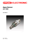
To open the Editor, proceed as follows:
• Start the HYDAC PC software CMWIN
• In the Extras Menu, select the "CM Editor" option.
• The following screen opens:
The menu structure and window properties of the Editor are explained below in greater
detail:
V03 R26 2011/08/24
HYDAC ELECTRONIC GMBH
Mat. No. 669844
PC-Software CMWIN V03
Page 33
5.6.1.1 File
•
With "New", you can establish which platform (CM device) the CM program is to
be created for before starting to create the CM program. The program functions
which are not available for the selected platform will be grayed out in the
Functions window and cannot be used during program generation.
•
With "Platform", you can establish which platform (CM device) the CM program
is to be created for during the creation of a CM program. The program functions
which are not available for the selected platform will be grayed out in the
Functions window and cannot be used during program generation.
•
Pressing "Open" allows you to open an already generated and stored CM
program. CM programs have the file extension *.hecmp. Select the required file
in the corresponding path.
•
Select "Save" to save a CM program. If the recording has not yet been saved,
the
“Save as…“ window will open. Enter the required file name in the
corresponding path.
•
To save a file that has not yet been saved or to save a file that has already
been
saved
under
a
different
name,
select
"Save as ..." . Enter the required file name in the corresponding path.
•
To integrate an existing program that has already been saved into the current
program generation process, select "paste from file". Select the required file in
the corresponding path.
•
Press "Print" to print out the content of the Linked functions window (=
program printout).
•
Press "Exit" to close the CM Editor.
V03 R26 2011/08/24
HYDAC ELECTRONIC GMBH
Mat. No. 669844
PC-Software CMWIN V03
Page 34
5.6.1.2 CM Program
•
After "Display" is selected, a window opens listing all the functions used in the
CM program which is currently open, together with inscriptions and parameters.
The list can be printed out by selecting "Print".
Pressing "Close“ takes you back to the CM Editor.
•
With "Simulate", you can simulate and/or test the CM program that is currently
open. The Simulation window opens for this purpose. It is not necessary for
the CM device to be connected for the simulation.
All of the input signals used in the CM program are listed one above the other
in the Name column in the left-hand part of the Simulation window.
You can assign a specific value to each input in the Input value column.
All of the actions used in the CM program are listed one above the other in the
Name column in the right-hand part of the Simulation window.
The current status of each action is displayed in the Value column.
The cycle number of the last status modification is displayed in the Cycle
column.
The date and time of the last status modification is displayed in the Time
column.
V03 R26 2011/08/24
HYDAC ELECTRONIC GMBH
Mat. No. 669844
PC-Software CMWIN V03
Page 35
With „Perform cycle", you can start the simulation for a single processing
cycle and view the resulting status modifications of the actions afterwards.
With "Start autom. cycle“, you start a permanent, continuous program
simulation. You can change the input values during the simulation however
you like and observe the status modifications of the actions.
With "End autom. cycle“, you stop the permanent, continuous program
simulation.
Click "Close“ to take you back to the CM Editor.
During the simulation, the assigned input values and action statuses are also
displayed in the Linked Functions window by means of corresponding
symbols.
V03 R26 2011/08/24
HYDAC ELECTRONIC GMBH
Mat. No. 669844
PC-Software CMWIN V03
•
Page 36
You can transfer the CM program which is currently open to the CM device (e.g.
CMU 1000) using "Transfer into device“.
Note!
Only error-free programs can be transferred into the CM device.
The following message appears after the program has been successfully
applied:
Here you can select whether you also wish to transfer the source code of the
program into the CM device.
Note!
If you also transfer the source code into the CM device, then it is available to
be read again by every other connected PC and modified! If the source code
is not transferred into the CM device, then the program cannot be read by
another PC.
The following message will appear if the CM program contains errors when
attempting transfer:
Eliminate the error(s) found in the CM program and transfer the program
again.
Note!
If you transfer a program and a power failure occurs during the transfer, then
the program will not be saved in the CM device after power is restored. For
that reason, first save your program on the PC on which it was originally
generated or modified before making the transfer.
V03 R26 2011/08/24
HYDAC ELECTRONIC GMBH
Mat. No. 669844
PC-Software CMWIN V03
Page 37
•
You can transfer and then edit the CM program currently available in the CM
device to your PC with "Receive from device". This will however only work if
the CM program source code from the original creator has also been
transferred into the CM device.
If no source code is available in the CM device, then the following message will
appear:
•
The "Online Debugging" function is a tool for observing the CM program as
well as for finding, diagnosing and eliminating possible errors in the CM
program and/or in the connected peripherals.
The following prerequisites must be fulfilled for this purpose:
- The CM device must be connected with the PC and the CMWIN software.
- The CM program opened in CMWIN and the one active in the CM device
must be identical.
If the "Online Debugging" mode is active, then the following values will be
displayed for the relevant functions:
- Measured values
- Constants
- Switching status of logical links
- Date and time when the corresponding event is triggered
The display in "Online Debugging" mode is shown in the following illustration,
as an example:
V03 R26 2011/08/24
HYDAC ELECTRONIC GMBH
Mat. No. 669844
PC-Software CMWIN V03
Page 38
5.6.1.3 Grouping
•
With Create grouping you can join several functions to make an cohesive unit
and move and copy these as a block.
First mark the functions to be grouped by enclosing them in a frame created
with the help of the cursor.
Afterwards, select “Group“ in the menu bar and then “Create grouping“ in the
drop-down menu that appears.
•
Press Cancel grouping to ungroup the functions which were linked together in
the group.
To do this, highlight the group concerned by clicking on any one of the
functions within the group.
Afterwards, select “Group“ in the menu bar and then “Cancel grouping“ in the
drop-down menu that appears.
5.6.1.4 Device
The "Connection“ function can be used to set up a connection between the PC and a
CM device from the CM Editor.
The function is identical with the connection setup in the CM Manager. (See Chap.
5.5.1)
V03 R26 2011/08/24
HYDAC ELECTRONIC GMBH
Mat. No. 669844
PC-Software CMWIN V03
Page 39
5.6.1.5 Sensor constellation
Reliable system monitoring means ensuring that exactly the same sensors that were
connected at the time the CM device was configured are connected during operation.
The Sensor constellation is used for this purpose. The sensor constellation is a
monitoring instrument for the connected sensor system, i.e. it performs a continuous
comparison between the connected "Actual" sensor system and the specified
"Reference" sensor system.
The sensor constellation is optional in the CM device and not mandatory. If however a
sensor constellation has been saved, then the connected sensor system must match it.
When there is an activated sensor constellation, then an "incorrect" sensor connected
by mistake will be recognized, thus preventing a situation in which the CM program is
working with incorrect information.
A sensor constellation can be saved in files and loaded from files, and can be both
received and transferred by the CM device.
The constellation files all have the extension *.hescf.
The sensor constellation contains the following data:
- Quantity of connected sensors
- Quantity of subchannels for each connected sensor
- Status of each individual subchannel (active/inactive)
- Sensor class (Analog / HSI / SMART)
- Units of the individual measured values
- Name of each sensor
- Device designation of each sensor
If a sensor constellation is available in the CM Editor, then you can use the correct
names in connection with the measurements during program generation. It will then be
the case that only those sensors and subchannels that are actually present will be
available and accessible for adjustment.
A status message at the lower edge of the window of the CM Editor indicates whether
or not a sensor constellation is available.
•
With the function Apply from file, you can open a saved sensor constellation
file and use it in the CM Editor.
To do this, enter the corresponding path and file name in the window that opens
and then click on Open.
•
With the function Apply from device, you transfer one of the sensor
constellations stored in the CM device to your PC, after which you can use it in
the CM Editor.
V03 R26 2011/08/24
HYDAC ELECTRONIC GMBH
Mat. No. 669844
PC-Software CMWIN V03
Page 40
•
With Delete you delete the currently available sensor constellation in the CM
Editor, after which it is no longer available for further use when generating
programs.
No saved constellation files are deleted!
•
To save a constellation file, select Save to file. Enter the appropriate path and
required file name for this purpose in the window that opens.
•
When the Display function is selected, a window opens in which the complete
sensor constellation is displayed.
V03 R26 2011/08/24
HYDAC ELECTRONIC GMBH
Mat. No. 669844
PC-Software CMWIN V03
Page 41
5.6.1.6 Sensor configuration
Sensor configuration is understood to mean all of the input-relevant settings in the CM
device (Peripherals settings). The sensor configuration can only be generated with the
CM device itself (offline generation in CMWIN is not possible). All necessary sensors
must be connected in order for this to be possible.
A sensor configuration can be saved in files and loaded from files, and can be both
received and transferred by the CM device.
The configuration files have the extension *.hedcf.
The sensor configuration contains the following data:
- Sensor name
- Mode
- Measurement range
- Decimals
- Units of the individual measured values
A status message at the lower edge of the window of the CM Editor indicates whether
or not a sensor configuration is available.
•
With the function Apply from file, you can open a saved sensor configuration
file and use it in the CM Editor.
To do this, enter the corresponding path and file name in the window that opens
and then click on Open.
•
With the function Apply from device, you transfer a sensor configuration
stored in the CM device to your PC, after which you can use it in the CM Editor.
•
With Delete you delete the currently available sensor constellation in the CM
Editor, after which it is no longer available for further use when generating
programs.
No saved constellation files are deleted!
•
To save a configuration file, select Save to file. Enter the relevant path and
required file name for this purpose in the window that opens.
V03 R26 2011/08/24
HYDAC ELECTRONIC GMBH
Mat. No. 669844
PC-Software CMWIN V03
•
Page 42
When the Display function is selected, a window opens in which the complete
sensor configuration file is displayed.
Note!
With a CM program, one has the opportunity of integrating not only a
configuration file but also a constellation file, so that one can define the
configuration and the constellation at the same time the CM program is
transferred into the CM device. Both parts are however optional and need not
be present in the CM program.
V03 R26 2011/08/24
HYDAC ELECTRONIC GMBH
Mat. No. 669844
PC-Software CMWIN V03
Page 43
5.6.1.7 Extras
•
The following window opens when the function Options is selected:
The selection buttons at the right-hand edge of the window appear after clicking
in the respective selection field.
- In the Language field, you can select either German, English or French as the
CMWIN system language.
- In the field Working folder you define the path for saving the CMWIN files
(CM programs, recordings, constellation and configuration files, ...).
- In the field Name as inscription you define whether or not the particular
function name (e.g. Measured value 2, Action 4) is to be displayed as the
function inscription in the "Linked functions" window.
If "No" is selected, then you have the option of entering an inscription text
manually into the function parameters.
- In the field Frame group you define whether or not a frame is to appear
around generated groups in the CM program.
Clicking on OK applies the settings and returns you to the main CMWIN
window.
Pressing Cancel takes you back without applying any changes.
•
Select the Display cycle time function to open the following window and to
display the current cycle time of the CM program.
Example:
V03 R26 2011/08/24
HYDAC ELECTRONIC GMBH
Mat. No. 669844
PC-Software CMWIN V03
Page 44
5.6.1.8 Window Divisions
The graphics interface of the CM Editor is divided into the following function windows:
"Function Properties" Window
The properties of the functions currently selected in the "Linked Functions" window
are displayed in this window. These include:
• Function name (e.g. Action 2; Constant 5; Measured value 12)
• Function type (e.g. Constant, Measured value, Timer)
• Specific properties (parameter settings)
• Comment
"Function List" Window
This window lists all the functions used in the CM program with the following
specifications:
• Function type (e.g. Constant, Measured value, Timer)
• Function name (e.g. Action 2; Constant 5; Measured value 12)
• Inscription (e.g. Working pressure N.I.O.)
"Linked Functions" Window
This window contains the actual CM program. The display can be zoomed in or out
with the scroll bar on the lower edge of the window.
"Functions" Window
This window contains all the functions available for program generation, sorted
according to:
• Data sources
• Calculations
• Numerical operations
• Conditions
• Links
• Boolean operations
• Result values/actions
• Other
V03 R26 2011/08/24
HYDAC ELECTRONIC GMBH
Mat. No. 669844
PC-Software CMWIN V03
Page 45
5.6.2 Options
•
The following window opens when the function Options is selected:
The selection buttons at the right-hand edge of the window appear after clicking
in the respective selection field.
- In the Language field, you can select either German, English or French as the
CMWIN system language.
- In the field Working folder you define the path for saving the CMWIN files
(CM programs, recordings, constellation and configuration files, ...).
- In the field Name as inscription you define whether or not the particular
function name (e.g. Measured value 2, Action 4) is to be displayed as the
function inscription in the "Linked functions" window.
If "No" is selected, then you have the option of entering an inscription text
manually into the function parameters.
- In the field Frame group you define whether or not a frame is to appear
around generated groups in the CM program.
Clicking on OK applies the settings and returns you to the main CMWIN
window.
Pressing Cancel takes you back without applying any changes.
5.6.3 Reset options
•
•
Using the Reset options function, you can reset all manually set options to the
factory default setting.
Confirm that all options are to be reset to the factory default setting by clicking
OK or press Cancel to go back without applying any changes.
5.7 Help
•
Select the Info function, to find out the present software version and to obtain
the link to the HYDAC website.
V03 R26 2011/08/24
HYDAC ELECTRONIC GMBH
Mat. No. 669844
PC-Software CMWIN V03
Page 46
APPENDIX A: CM Program Functions
A CM program consists of many individual functions that are linked with one another
and that are processed and evaluated cyclically.
A.1 General Information on Functions
A function has Inputs, Outputs and Parameters. This means, for example, the function
"Median value" reads a numerical value at the input, forms a median value above it and
then displays this at the output. A parameter is used to define the amount of time for
which the calculation is rendered.
A.1.1 Inputs / Outputs
For most functions, the outputs change during the running time, depending on the
input. Functions are linked with one another in the Editor. This means, for example,
that the output of a function can be linked with the input of a different function. It is
possible to make one output dependent on several inputs, but not several outputs on
one input.
There are two types of inputs/outputs, depending on the value type: Numerical and
Boolean. A "Boolean output" can only be linked with a "Boolean input" and a numerical
output can only be linked with a "numerical input".
A.1.2 Numerical Values
A numerical value is a decimal number, i.e. a numerical value with an optional
plus/minus sign and any number of digits after the decimal point. It is accurate to 7-8
significant places. That means that with a value of 2 million (7 places in front of the
decimal point), the addition of a value of 0.001 (3 places after the decimal point) will not
alter the numerical value. One would need accuracy to at least 10 significant places for
it to be altered.
Numerical inputs/outputs and the corresponding connection lines are shown in blue.
Boolean Values
A Boolean value is a logical status. There are only 2 statuses: "true" or "1" and false or
"0".
Boolean inputs/outputs and the corresponding connection lines are shown in green.
V03 R26 2011/08/24
HYDAC ELECTRONIC GMBH
Mat. No. 669844
PC-Software CMWIN V03
Page 47
A.1.3 Parameters
Parameters are defined in the Editor and do not change during the running time. One
exception to this are the input parameters, which can be modified during the running
time in a menu on the CM device or using a PC which is connected.
Parameters have one of the following types:
Numerical Parameters
A numerical parameter is a decimal number in accordance with the inputs/outputs.
Whole Number
A whole number is a natural number, i.e. it has no digits after the decimal point. As a
rule, no negative numbers are permitted either. Whole numbers are used for example
for numbering purposes.
Input List
An entry from a list is selected for the input list type. The quantity and the type of list
entries is dependent on the particular parameter.
Boolean Parameters
A Boolean parameter has, as already described in connection with the inputs/outputs,
only two logical statuses: "0" and "1". Nevertheless, it is not "0" and "1" that are set in
the Editor, but rather such terms as "No" or "Yes", "Inactive" or "Active", "Off" or "On",
depending on the context.
Character String
A character string is an arbitrary text, the length of which is usually limited. In addition,
any leading and subsequent empty spaces are usually removed automatically.
Values Table
A values table is a table with several values, whereby each value is positioned in a line
of its own.
Furthermore, it is also possible to enter value pairs. The individual values of a value
pair are then separated from one another with a colon ":".
Time
The time of the day is specified in the country-specific format that is set in Windows.
V03 R26 2011/08/24
HYDAC ELECTRONIC GMBH
Mat. No. 669844
PC-Software CMWIN V03
Page 48
A.2 Data Sources
A.2.1 Numerical Constants
The Numerical Constants function supplies a numerical value which
is defined in the Editor and which does not change during the
running time.
That means that the Value parameter entered in the Editor is output
during the running time at the output.
Inputs:
Outputs:
Parameters:
y:
p1:
(Numerical)
Value (Numerical)
A.2.2 Measured Value
The Measured Value function provides the current measured value
of a connected sensor.
The Sensor connection parameter is used to define the sensor; the
channel of the sensor with Subchannel. If a connected sensor has
no subchannel, then no selection is possible at this point.
If a sensor constellation has been saved, then only the active
connections are displayed in the input lists for the Sensor
connection, each of them with the respective sensor name. The
subchannels available for this sensor are then displayed at
Subchannel, each of them with name and unit.
If no sensor constellation is saved, then Ports "A" to "P" are offered
for selection at Sensor connection and Channels "1" to "32"
at Subchannel.
Inputs:
Outputs:
Parameters:
y:
p1:
p2:
(Numerical)
Sensor connection (input list)
Subchannel (input list)
A.2.3 Digital Input
The Digital input function supplies the status of a digital input.
The Input terminal parameter is used to define which digital input
port is used.
Inputs:
Outputs:
Parameters:
V03 R26 2011/08/24
y:
p1:
(Boolean)
Input terminal (input list)
HYDAC ELECTRONIC GMBH
Mat. No. 669844
PC-Software CMWIN V03
Page 49
A.2.4 Numerical Entry
The function Numerical input supplies a numerical value which can
be adjusted in the Parameters menu of the CM device. As an
alternative, it can also be set via a connected PC.
The Inscription parameter is used as a menu option in the input
menu for this purpose. The permissible input range runs from
-2,000,000.00 to +2,000,000.00.
Modifications made in the CM device during the running time also
remain in effect after switch-off. The value that is set under Start
value will used after the first-time transfer of the CM program to the
CM device until the first change is made.
Inputs:
Outputs:
Parameters:
y:
p1:
p2:
(Numerical)
Starting value (Numerical)
Inscription (character string)
A.2.5 Boolean Entry
The Boolean input function supplies a Boolean value, which can be
set
in
the
Parameters
menu
of
the
CM
device.
As an alternative, it can also be set via a connected PC.
The Inscription parameter is used as a menu option in the input
menu for this purpose. On the CM device input is by selecting "Yes"
or "No", on the PC, a checkbox appears.
Modifications made in the CM device during the running time also
remain in effect after switch-off. The value that is set under Start
value will used after the first-time downloading of the CM program
into the CM device until the first change is made.
The Functionality parameter defines how the input is interpreted.
The following settings are possible:
Switch
A menu option is generated on the CM device with which the input
value can be switched on or off. This functionality is used to activate
certain paths in the evaluation logic.
Key
When the value on the CM device is switched on, then only one
impulse is generated in the evaluation logic and the option switches
itself off in the menu again immediately. A key function is simulated,
so to speak. This functionality can be used to trigger events in the
evaluation logic.
Inputs:
Outputs:
Parameters:
V03 R26 2011/08/24
y:
p1:
p2:
p3:
(Boolean)
Starting value (Boolean)
Inscription (character string)
Functionality (entry list)
HYDAC ELECTRONIC GMBH
Mat. No. 669844
PC-Software CMWIN V03
Page 50
A.2.6 Timer
The Timer is a function which generates an impulse at an adjustable
interval (e.g. every minute, every 5 minutes), i.e. setting its Boolean
output to "1" for a cycle and then back to "0".
The following settings are possible for the Interval parameter:
• 1; 2; 5; 10; 15; 30 Seconds,
• 1; 2; 5; 10; 15; 30 Minutes,
• 1; 2; 6; 12; 24 Hours.
The output impulse is thereby always synchronized with the time of
day. If, for example, "6 hours" is set, then an impulse will be
generated at 6 AM, 12 AM, 18 PM and 0 PM.
If an impulse is required at particular times of the day, then you
should use a clock timer with a downstream impulse generator
instead of a timer (see Chap. A.8.5).
Inputs:
Outputs:
Parameters:
y:
p1:
(Boolean)
Interval (input list)
A.2.7 Clock Timer
The Clock timer is a function which switches on its Boolean output at
a certain time during a month and then switches it off again at a
different point in time.
The switch-on time is set using the parameters Switch-on day and
Switch-on time, while the switch-off time is set using the parameters
Switch-off day and Switch-off time.
A day of the week "Monday" to "Sunday" can be set. The setting
"Daily" is also possible. The "Daily" setting is only possible if both
days are set to "Daily". The Editor prevents incorrect inputs: If, for
example, the switch-on day is changed from "Monday" to "Daily",
then the switch-off day is automatically set to "Daily".
If switch-on time and switch-off time are identical, then the output
will be switched on for precisely this specified second.
If only one impulse is required, i.e. if the output is to be set for
exactly one cycle to "1" at the switch-on point and then back to "0",
then use a downstream impulse generator (see Chap. A.8.5).
Inputs:
Outputs:
Parameters:
V03 R26 2011/08/24
y:
p1:
p2:
p3:
p4:
(Boolean);
Switch-off day (input list)
Switch-off time (time of day)
Switch-on day (input list)
Switch-on time (time of day)
HYDAC ELECTRONIC GMBH
Mat. No. 669844
PC-Software CMWIN V03
Page 51
A.2.8 Error Event
Error handling can be implemented with the function Error event.
The Boolean output is switched to "1" when an error condition is
present. The output is switched back to "0" if the error disappears.
The type of error event can be set with the Event parameter.
The following events are possible:
Below signal range
A sensor has a cable break, for example
Above signal range
The signal of one sensor is above the signal range
Incorrect sensor constellation
There is either no sensor, or an incorrect sensor connected to one
sensor connection port.
Numerical error
An error occured during a calculation, e.g. division by 0 or square
root of a negative number, logarithm from 0, etc.
Cycle time exceeded
The set cycle time was exceeded.
Inputs:
Outputs:
Parameters:
y:
p1:
(Boolean)
Event (input list)
A.2.9 Boolean Constants
The Boolean Constant function supplies a Boolean value which is
defined in the Editor and which does not change during the running
time. That means that the parameter entered in the Editor is output
during the running time at the output.
Inputs:
Outputs:
Parameters:
y:
p1:
(Boolean)
Value (Boolean)
A.2.10 State-bit
The function Show Stat-bit provides the status of the bit defined by
the "Sensor port" and "Bit location" parameters in the status code of
the selected SMART sensor (status code is sensor-specific) at the
Boolean output.
Inputs
Outputs:
Parameters:
V03 R26 2011/08/24
y:
p1:
p2:
(Boolean)
Sensorport (Channel A .. Channel H)
Bit location (0 .. n -sensorabhängig-)
HYDAC ELECTRONIC GMBH
Mat. No. 669844
PC-Software CMWIN V03
Page 52
Additional points for Sequence controls in the CMU
The two interrelated function components Sequence and Transition can be used to
implement the functionality of Sequence controls or finite state machines.
A.2.11 Sequence
The Sequence component has a numerical output. This represents
the current state of the Sequence. At the same time, a number is
allocated to all states. The term 'Sequence' has been taken from
control engineering. Typically several steps are completed one
after the other in a Sequence. Branches and backward jumps are
however possible. A sequence can adopt several states which are
numbered in ascending order starting at "0". "0" is always the state
following switch-on. A change in state is always triggered by a
transition.
Inputs:
Outputs:
Parameters:
y:
-
(Numerical)
A.2.12 Transition (in the field "Result values / Actions")
The Transition component serves to bring about a change from one
state to another in a Sequence. A transition has a Boolean input
and has 4 parameters.
Inputs:
Outputs:
Parameters:
x:
p1:
p2:
(Boolean)
Sequence
Name of the related Sequence in the application
program
Current state
Number of the state while the input condition is
scrutinized.
With the "ignore" setting, the current Sequence state is
ignored, i.e. the input condition is continually
scrutinized, irrespective of the current state of the
sequence.
Successor state
p3:
• State which is adopted once the input condition occurs.
p4:
Dwell time [s]
Indicates how many seconds the Sequence must be in
the current state before the input condition is
scrutinized for the successor state.
For one Sequence, several transitions with identical current and
successor states but with differing input conditions can be used in
the application program. This enables branching into different
Sequence cascades within a Sequence.
V03 R26 2011/08/24
HYDAC ELECTRONIC GMBH
Mat. No. 669844
PC-Software CMWIN V03
Page 53
A.3 Numerical Calculations
A.3.1 Addition
The Addition function returns the sum of the two input values at the
output:
y = x1 + x2
Inputs:
Outputs:
Parameters:
x1:
x2:
y:
-
(Numerical)
(Numerical)
(Numerical)
A.3.2 Subtraction
The Subtraction function returns the difference between the two
input values at the output:
y = x1 - x2
Inputs:
Outputs:
Parameters:
x1:
x2:
y:
-
(Numerical)
(Numerical)
(Numerical)
A.3.3 Multiplication
The Multiplication function returns the product of the two input
values at the output:
y = x1 * x2
Inputs:
Outputs:
Parameters:
x1:
x2:
y:
-
(Numerical)
(Numerical)
(Numerical)
A.3.4 Division
The Division function returns the quotient of the two input values at
the output:
y = x1 / x2
Inputs:
Outputs:
Parameters:
V03 R26 2011/08/24
x1:
x2:
y:
-
(Numerical)
(Numerical)
(Numerical)
HYDAC ELECTRONIC GMBH
Mat. No. 669844
PC-Software CMWIN V03
Page 54
A.3.5 Division Remainder
The Division remainder function returns the division remainder (the
modulo) of the two input values at the output . The division
remainder is determined by performing a whole number division x1 /
x2 and outputting the remainder of this division as output value.
If the input x1 counts upward, e.g. sequentially by 1, and the input x2
amounts to 5, the the output will count around from 0 to 4.
Inputs:
Outputs:
Parameters:
x1:
x2:
y:
-
(Numerical)
(Numerical)
(Numerical)
A.3.6 Absolute Value
The Absolute value function returns the input value without a
plus/minus sign at the output:
y = |x|
Inputs:
Outputs:
Parameters:
x:
y:
-
(Numerical)
(Numerical)
A.3.7 Change of Sign
The Change of sign function returns the inverse input value at the
output:
y = -x
Inputs:
Outputs:
Parameters:
x:
y:
-
(Numerical)
(Numerical)
A.3.8 Rounding
The Rounding function returns the rounded input value at the output.
With this function, it is possible not only to round to whole decimal
places, but also to whole-number multiples of a step.
The size of the step is specified in the Step parameter.
If the step size is 20, for example, then all values between -10 and
10 will be rounded off to 0, all values between 10 and 30 to 20, and
so on.
Inputs:
Outputs:
Parameters:
V03 R26 2011/08/24
x:
y:
p1:
(Numerical)
(Numerical)
Step (Numerical)
HYDAC ELECTRONIC GMBH
Mat. No. 669844
PC-Software CMWIN V03
Page 55
A.3.9 Raising to a Higher Power
The Raising to a higher power function supplies the power of the
input value at the output.
The exponent is set using the Exponent parameter.
Inputs:
Outputs:
Parameters:
x:
y:
p1:
(Numerical)
(Numerical)
Exponent (Numerical)
A.3.10 Square Root
The Square root function supplies the square root of the input value
at the output.
If the input value is negative, then the value 0 will be supplied at the
output and an error flag will be set. One can react to this situation
with the Error event function (see Chap. A.2.8).
If a negative input can occur in everyday practice, then you should
structure the corresponding behavior in accordance with your
preferences with the functions Absolute value, If-then-else and Less
than (see Chap. A.3.6, A.4.4 and A.6.5).
Inputs:
Outputs:
Parameters:
x:
y:
-
(Numerical)
(Numerical)
A.3.11 Power at Base e
The Power at base e function supples the power at base e at the
output.
The input value is used as the exponent.
Inputs:
Outputs:
Parameters:
x:
y:
-
(Numerical)
(Numerical)
A.3.12 Natural Logarithm
The Natural logarithm function supplies the logarithm of the input
value at base e at the output.
If the input value is negative or 0, then the value 0 will be supplied at
the output and an error flag will be set. One can react to this
situation with the Error event function (see Chap. A.2.8).
If a negative input can occur in everyday practice, then you should
structure the corresponding behavior in accordance with your
preferences with the functions Absolute value, If-then-else and Less
than (see Chap. A.3.6, A.4.4 and A.6.5).
Inputs:
Outputs:
Parameters:
V03 R26 2011/08/24
x:
y:
-
(Numerical)
(Numerical)
HYDAC ELECTRONIC GMBH
Mat. No. 669844
PC-Software CMWIN V03
Page 56
A.3.13 Decade Logarithm
The Decade logarithm function supplies the logarithm of the input
value at base 10 at the output.
If the input value is negative or 0, then the value 0 will be supplied at
the output and an error flag will be set. One can react to this
situation with the Error event function (see Chap. A.2.8).
If a negative input can occur in everyday practice, then you should
structure the corresponding behavior in accordance with your
preferences with the functions Absolute value, If-then-else and Less
than (see Chap. A.3.6, A.4.4 and A.6.5).
Inputs:
Outputs:
Parameters:
x:
y:
-
(Numerical)
(Numerical)
A.3.14 Integral
The Integral function supplies the integral of the input value over
time at the output. The output is always calculated with the unit of
seconds. This means that the input value 6 causes the output to
increase every second by 6. The trapezoidal rule is applied to make
the calculation.
The function still has a Boolean reset input. If the value "1" is
pending there, then the value "0" will be set up at the output.
Furthermore, the integral function also has an automatic anti-windup mechanism. It is with this that a parameterizable Lower limit and
Upper limit are set for the output.
This function adopted from control engineering has the following
background:
If a control variable is not achieved, then the I ratio continues to
integrate further. The controller then may require under certain
circumstances a very long time to exit this range again if the
actuating variable reverses its sign. This can lead to very unstable
behavior.
Inputs:
Outputs:
Parameters:
V03 R26 2011/08/24
x1:
x2:
y:
p1:
p2:
Input value (Numerical)
Reset input (Boolean)
(Numerical)
Lower limit (Numerical)
Upper limit (Numerical)
HYDAC ELECTRONIC GMBH
Mat. No. 669844
PC-Software CMWIN V03
Page 57
A.3.15 Differential Quotient
The Differential quotient function supplies the derivation of the input
value over time at the output. The output is always calculated with
the unit of seconds. This means that an increase of the input value
from 5 to 6 in one second will yield an output value of 1.
The differential quotient is formed and filtered numerically by the
difference quotient. This filtering is necessary for the following
reasons:
In view of the fact that the input values usually arise from a
quantized measured value, e.g. in connection with the digitization of
an analog quantity, these values will have what is called a
quantizing distortion. This means that the digitization causes the
value to fluctuate by the amount of the resolution. For example, with
a 12-bit resolution, a value of 600 bar that was resolved with 12 bit
will fluctuate back and forth by 0.15 bar. If the difference quotient is
formed now every millisecond, then this quantizing distortion will be
amplified by a factor of 1000. That means that, without filtering, the
output would jump back and forth between + and - 150 bar/s.
The filter can be set with the Filtering parameter. The setting
corresponds thereby to the time range during which the filtering
takes place. Nonetheless, no pure median value formation will be
used as a filter, but rather a special algorithm instead.
The following settings are possible:
• switched off, • 200 ms, • 1 second
Inputs:
Outputs:
Parameters:
V03 R26 2011/08/24
x1:
y:
p1:
• 5 seconds.
(Numerical)
(Numerical)
Filtering (entry list)
HYDAC ELECTRONIC GMBH
Mat. No. 669844
PC-Software CMWIN V03
Page 58
A.4 Numerical Operations
A.4.1 Minimum
The Minimum function supplies the smaller of the two input values at
the output.
Inputs:
Outputs:
Parameters:
x1:
x2:
y:
-
(Numerical)
(Numerical)
(Numerical)
A.4.2 Maximum
The Maximum function supplies the larger of the two input values at
the output.
Inputs:
Outputs:
Parameters:
x1:
x2:
y:
-
(Numerical)
(Numerical)
(Numerical)
A.4.3 Limit
The Limit function limits the input value x1, and makes it available at
the output.
The two limits are set by the input values x2 and x3. If x1 is less than
x2, then x2 will be output, if x1 is greater than x3, then x3 will be
output, otherwise x1.
Inputs:
Outputs:
Parameters:
x1:
x2:
x3:
y:
-
Input value (Numerical)
Lower limit
(Numerical)
Upper limit
(Numerical)
(Numerical)
A.4.4 If - Then - Else
The function If-Then-Else has two numerical inputs x1 and x2 as well
as a Boolean input x3.
If the Boolean input value is "1", then the input value of x1 is output
at the output, otherwise the value of x2.
Inputs:
Outputs:
Parameters:
V03 R26 2011/08/24
x1:
x2:
x3:
y:
-
(Numerical)
(Numerical)
(Boolean)
(Numerical)
HYDAC ELECTRONIC GMBH
Mat. No. 669844
PC-Software CMWIN V03
Page 59
A.4.5 Median Value
The Median value function supplies the arithmetical median value of
the input values over an adjustable time range.
The time range is set in seconds using the Time parameter.
The median value is formed according to the "Repeating Average"
procedure. This means that, when the time setting is "2 seconds",
for example, the input values are compiled for 2 seconds, then
averaged and output at the output. The next median value interval
begins after that. The output value pauses on the last median value.
Inputs:
Outputs:
Parameters:
x:
y:
p1:
Input value (Numerical)
Median value (Numerical)
Time (Numerical)
A.4.6 Extended Average
The Extended Average function supplies the arithmetic average of
the numerical input value at the output. The interval over which the
average value is generated, is controlled using a boolean reset
input.
If the reset input has the value "1", then the input value is passed
directly to the output. If the signal on the reset input falls from "1" to
"0", then from this point, the arithmetic average of the input value is
given at the output.
Inputs:
Outputs:
Parameters:
x1:
x2:
y:
-
Input value (Numerical)
Reset (Boolean)
(Numerical)
A.4.7 Note Value
The Note value function is used to hold on to certain values (to
freeze them). It has one numerical and one Boolean input.
If the Boolean input value is "1", then the numerical input value is
output at the output. If the Boolean input value is "0", then the last
output value continues to be output.
If the value is only to be applied for one flank of the Boolean input,
then you can put the function Pulse generation upstream from it (see
Chap. A.8.5).
Inputs:
Outputs:
Parameters:
V03 R26 2011/08/24
x1:
x2:
y:
-
Input value (Numerical)
Switch value through (Boolean)
(Numerical)
HYDAC ELECTRONIC GMBH
Mat. No. 669844
PC-Software CMWIN V03
Page 60
A.4.8 Note Minimum
The Note minimum function supplies as the output value the
smallest value that the input value has yet reached.
If the input value is greater than the output value, then the output
value remains unchanged. If the input value is less, then the output
value will be reset.
The minimum can be reset with the Boolean input x2. The input
value will be applied directly at the output for as long as this input is
"1".
Inputs:
Outputs:
Parameters:
x1:
x2:
y:
-
Input value (Numerical)
Reset (Boolean)
(Numerical)
A.4.9 Note Maximum
The Note maximum function supplies as the output value the largest
value that the input value has yet reached.
If the input value is less than the output value, then the output value
remains unchanged. If the input value is greater, then the output
value will be reset.
The maximum can be reset using the Boolean input x2. The input
value will be applied directly at the output for as long as this input is
"1".
Inputs:
Outputs:
Parameters:
V03 R26 2011/08/24
x1:
x2:
y:
-
Input value (Numerical).
Reset (Boolean)
(Numerical)
HYDAC ELECTRONIC GMBH
Mat. No. 669844
PC-Software CMWIN V03
Page 61
A.4.10 Tabular Value
With the function Tabular value, the output value is obtained from a
parameterized number table. The input value functions thereby as
number of the table entry.
If the whole number value of the input is 0 or less, then the first
value of the table will be output; if it is 1, then the second value; and
so on up to the last tabular value. If the input value is greater than
the number of tabular entries, then the last table entry will be output.
As a basic rule, the input value will be rounded to a whole number.
The table is defined using the Table parameter. Each value must
have a line of its own at the time of entry. Empty lines are removed
automatically. The number of values will also be defined
automatically on the basis of the available lines. It must be between
2 and 20.
The Tabular value function can be used for example as a
downstream element of a division remainder in order to specify
various values one after the other (see Chap. A.3.5).
Inputs:
Outputs:
Parameters:
x:
y:
p1:
Index of the selected tabular value (Numerical)
Selected value (Numerical)
Table (values table)
A.4.11 Tabular Index
The Tabular index function is the counterpart to the Tabular value
function. The input value is sorted into a parameterizable numerical
table, which must be organized in order of increasing values, and
the number of the tabular entry is output.
If, for example, the first tabular entry is 4 and the second is 7.8, then
a 0 will be output for all input values less than 4, the value 1 will be
output for all values between 4 and 7.8, and the value 2 for all
values greater than 7.8.
The table is defined using the Table parameter. Each value must
have a line of its own at the time of entry. Empty lines are removed
automatically. The number of values will also be defined
automatically on the basis of the available lines. It must be between
2 and 20.
This function can be used for flexible range definition. Thus, for
example, limit values can be defined in the table when a value is
normal, suspicious, critical and very critical.
Inputs:
Outputs:
Parameters:
V03 R26 2011/08/24
x:
y:
p1:
Value in the table (Numerical).
Index of the value / Value range (Numerical).
Table (values table)
HYDAC ELECTRONIC GMBH
Mat. No. 669844
PC-Software CMWIN V03
Page 62
A.4.12 Characteristic curve
The Characteristic curve function is used to convert input values
from one range into another. The conversion can be subdivided into
various segments through the specification of up to 20 nodes.
The Table parameter is used to specify the nodes. Each value pair
is in a different line in the table. The values for x and y are separated
by a colon. The x values must be listed in ascending order. No x
value may appear more than once. Empty lines are removed
automatically. The number of values will also be defined
automatically on the basis of the available lines. It must be between
2 and 20.
The ranges between the nodes are interpolated linearly; the values
outside the nodes are extrapolated from the last segment. A
limitation is easy to set up by simply setting another node nearby
that has the same y value. If for example the range of 0 to 450 is to
be converted to percent and at the same time limited to 0 and 100,
then this is accomplished with the following value pairs:
-1:
0:
450:
451:
Inputs:
Outputs:
Parameters:
x:
y:
p1:
0
0
100
100
X value of the characteristic curve (Numerical).
Function value from the characteristic curve (Numerical)
Table (values table)
A.4.13 Slope
The Slope function is used to prevent rapid value changes. Under
stable conditions, the input value is shown at the output. Changes of
the input value are however not passed along directly to the output,
but rather only in small steps. Like a slope, so to speak. Different
slopes can be defined thereby for positive and negative value
modifications.
The parameters Descending slope and Ascending slope are used to
specify the maximum permissible value changes per second.
If for example the value 5 is set for Ascending ramp and the input
value jumps from 0 to 100, then the output will be only slowly
increased, and it will take 20 seconds for the output value to reach
100.
Inputs:
Outputs:
Parameters:
V03 R26 2011/08/24
x:
y:
p1:
p2:
(Numerical)
(Numerical)
Descending slope (Numerical)
Ascending slope (Numerical)
HYDAC ELECTRONIC GMBH
Mat. No. 669844
PC-Software CMWIN V03
Page 63
A.5 Counting Functions
A.5.1 Count Pulses
The Count pulses function has three Boolean inputs and one
numerical output. If the Counting input has the value "1", then the
changes from "0" to "1" at the Pulses input will be counted and the
count value will be set at the output. If the Reset input is at "1", then
the count value, and thus the output as well, will be "0".
Flexible counting structures can thus be obtained by placing the
Pulse generation function upstream (see Chap. A.8.5). The
placement of a downstream Note value function (see Chap. A.4.6)
also makes it possible to implement a counter with an interim status.
Inputs:
Outputs:
Parameters:
x1:
x2:
x3:
y:
-
Pulses (Boolean)
Counting (Boolesch)
Reset (Boolean)
Count value (Numerical)
A.5.2 Stop watch
The Stop watch function has two Boolean inputs and one numerical
output. If the Start/Stop input has the value "1", then the seconds will
be counted and the time will be applied at the output. If the Reset
input is at "1", then the time, and thus the output as well, will be "0".
The behavior at the output can be controlled with the Output
parameter.
Two settings are possible:
Current time
The output value is the current number of seconds counted.
Stopped time
The output value is not the current quantity, but rather the most
recently measured quantity. This means that the current count is set
to the output whenever the time is stopped with the Start/Stop input.
Flexible time measurement structures can thus be obtained by
placing the Pulse generation function upstream (see Chap. A.8.5).
Inputs:
Outputs:
Parameters:
V03 R26 2011/08/24
x1:
x2:
y:
p1:
Start/Stop (Boolean)
Reset (Boolean)
(Numerical)
Output (entry list)
HYDAC ELECTRONIC GMBH
Mat. No. 669844
PC-Software CMWIN V03
Page 64
Numerical Conditions
A.6.1 Equals
The Equals function compares two numerical input values for
equivalence and outputs a "1" at its Boolean output if the values are
equivalent, otherwise a "0".
With the Precision parameter, you can adjust how precise the
comparison is. For this the following explanation:
In view of the fact that numerical values are presented on computers
as floating point numbers with finite precision, normal comparisons
usually fail. Thus, for example, the finite precision of 2/6 is not
necessarily the same as the result of 1/3. The difference is not to be
found before the 8th decimal place, but nonetheless the two values
are not recognized as being equivalent.
The point at which one needs to break off the comparison of
numbers varies from case to case. It is for that reason that you have
the option of controlling the precision of the comparison.
If you specify 0.01 for precision, for example, then the numbers
12.453 and 12.458 will still be recognized as equivalents to one
another, because the difference is less than 0.01.
Inputs:
Outputs:
Parameters:
x1:
x2:
y:
p1:
(Numerical)
(Numerical)
(Boolean)
Precision (Numerical)
A.6.2 Does not Equal
The Does not equal function compares two numerical input values
for equivalence and outputs a "1" at its Boolean output if the values
are not equal, otherwise a "0".
For the Precision parameter, see the explanation in the Equals
function (Chapter A.6.1).
Inputs:
Outputs:
Parameters:
V03 R26 2011/08/24
x1:
x2:
y:
p1:
(Numerical)
(Numerical)
(Boolean)
Precision (Numerical)
HYDAC ELECTRONIC GMBH
Mat. No. 669844
PC-Software CMWIN V03
Page 65
A.6.3 Greater than
The Greater than function compares two numerical input values for
equivalence and outputs a "1" at its Boolean output if value x1 is
greater than x2, otherwise a "0".
In view of the fact that numerical values are presented on computers
as floating point numbers with finite precision, it is difficult to make
decisions in border ranges. (See the explanation in Chapter A.6.1,
Equals function). This is however usually irrelevant in everyday
usage, because the imprecision is not to be found before the 8th
significant decimal place.
When however it is important that a precise decision be made for a
border range, then you can install the Rounding function upstream
(see Chap. A.3.8).
Inputs:
Outputs:
Parameters:
x1:
x2:
y:
-
(Numerical)
(Numerical)
(Boolean)
A.6.4 Greater than or Equal to
The Greater than or equal to function compares two numerical input
values for equivalence and outputs a "1" at its Boolean output if
value x1 is greater than or equal to x2, otherwise a "0".
For more on the subject of precision, please note the explanations in
the Greater than function (see Chapter A.6.3).
Inputs:
Outputs:
Parameters:
x1:
x2:
y:
-
(Numerical)
(Numerical)
(Boolean)
A.6.5 Less than
The Less than function compares two numerical input values for
equivalence and outputs a "1" at its Boolean output if value x1 is less
than x2, otherwise a "0".
For more on the subject of precision, please note the explanations in
the Greater than function (see Chapter A.6.3).
Inputs:
Outputs:
Parameters:
V03 R26 2011/08/24
x1:
x2:
y:
-
(Numerical)
(Numerical)
(Boolean)
HYDAC ELECTRONIC GMBH
Mat. No. 669844
PC-Software CMWIN V03
Page 66
A.6.6 Less than or Equal to
The Less than or equal to function compares two numerical input
values for equivalence and outputs a "1" at its Boolean output if
value x1 is less than or equal to x2, otherwise a "0".
For more on the subject of precision, please note the explanations in
the Greater than function (see Chapter A.6.3).
Inputs:
Outputs:
Parameters:
x1:
x2:
y:
-
(Numerical)
(Numerical)
(Boolean)
A.6.7 Within
The Within function compares three numerical input values for
equivalence and outputs a "1" at its Boolean output if value x1 is
greater than or equal to x2, and smaller than or equal to x3,
otherwise a "0".
For more on the subject of precision, please note the explanations in
the Greater than function (see Chapter A.6.3).
Inputs:
Outputs:
Parameters:
x1:
x2:
x3:
y:
-
(Numerical)
(Numerical)
(Numerical)
(Boolean)
A.6.8 Outside
The Outside function compares three numerical input values for
equivalence and outputs a "1" at its Boolean output if value x1 is
smaller than x2 or greater than x3, otherwise a "0".
For more on the subject of precision, please note the explanations in
the Greater than function (see Chapter A.6.3).
Inputs:
Outputs:
Parameters:
V03 R26 2011/08/24
x1:
x2:
x3:
y:
-
(Numerical)
(Numerical)
(Numerical)
(Boolean)
HYDAC ELECTRONIC GMBH
Mat. No. 669844
PC-Software CMWIN V03
Page 67
A.7 Boolean Links
A.7.1 Not
The Not function supplies the negated Boolean input value at its
Boolean output.
If x = "0", then a "1" is output, otherwise a "0".
Inputs:
Outputs:
Parameters:
x:
y:
-
(Boolean)
(Boolean)
A.7.2 And
The And function links the two Boolean inputs with the "and"
operation and supplies the result to its Boolean output.
The output is then "1" only if both inputs are "1", otherwise it is "0".
The following log table makes this function clear.
x1
x2
y
0
0
0
0
1
0
1
0
0
1
1
1
Inputs:
Outputs:
Parameters:
x1:
x2:
y:
-
(Boolean)
(Boolean)
(Boolean)
A.7.3 Not - And
The Not - And function links the two Boolean inputs with the "nand"
operation and supplies the result to its Boolean output.
The output is then "0" only if both inputs are "1", otherwise it is "1".
The following log table makes this function clear.
x1
x2
y
0
0
1
0
1
1
1
0
1
1
1
0
Inputs:
Outputs:
Parameters:
V03 R26 2011/08/24
x1:
x2:
y:
-
(Boolean)
(Boolean)
(Boolean)
HYDAC ELECTRONIC GMBH
Mat. No. 669844
PC-Software CMWIN V03
Page 68
A.7.4 Or
The Or function links the two Boolean inputs with the "or" operation
and supplies the result to its Boolean output.
The output is "1" if one of the two inputs is "1". If both are "0", then
the output will also be "0".
The following log table makes this function clear.
x1
x2
y
0
0
0
0
1
1
1
0
1
1
1
1
Inputs:
Outputs:
Parameters:
x1:
x2:
y:
-
(Boolean)
(Boolean)
(Boolean)
A.7.5 Not - Or
The Not - Or function links the two Boolean inputs with the "nor"
operation and supplies the result to its Boolean output.
The output is "0" if one of the two inputs is "1". If both of the inputs
are "0", then the output will be "1".
The following log table makes this function clear.
x1
x2
y
0
0
1
0
1
0
1
0
0
1
1
0
Inputs:
Outputs:
Parameters:
V03 R26 2011/08/24
x1:
x2:
y:
-
(Boolean)
(Boolean)
(Boolean)
HYDAC ELECTRONIC GMBH
Mat. No. 669844
PC-Software CMWIN V03
Page 69
A.7.6 Exclusive Or
The Exclusive Or function links the two Boolean inputs with the "xor"
operation and supplies the result to its Boolean output.
The output is "1" if precisely one of the two inputs is "1". If both of
the inputs are "0" or if both of the inputs are "1", then the output will
be "0". One can also say that the output is then precisely "1" if the
two inputs are not equivalent.
The following log table makes this function clear.
x1
x2
y
0
0
0
0
1
1
1
0
1
1
1
0
Inputs:
Outputs:
Parameters:
x1:
x2:
y:
-
(Boolean)
(Boolean)
(Boolean)
A.7.7 Not Exclusive Or
The Not Exclusive Or function links the two Boolean inputs with the
"nxor" operation and supplies the result to its Boolean output.
The output is "0" if precisely one of the two inputs is "1". If both of
the inputs are "0" or if both of the inputs are "1", then the output will
be "1". One can also say that the output is then precisely "1" if the
two inputs are equivalent.
The following log table makes this function clear.
x1
x2
y
0
0
1
0
1
0
1
0
0
1
1
1
Inputs:
Outputs:
Parameters:
V03 R26 2011/08/24
x1:
x2:
y:
-
(Boolean)
(Boolean)
(Boolean)
HYDAC ELECTRONIC GMBH
Mat. No. 669844
PC-Software CMWIN V03
Page 70
A.8 Other Boolean Operations
A.8.1 Note Switching Status
The Note switching status function is used to hold on to a Boolean
value (to freeze it). It has two Boolean inputs.
If the input value x2 is "1", then the input value x1 is output at the
output. If the input value x2 is "0", then the last output value remains
in effect.
If the value is only to be applied for one flank, then you can put the
function Pulse generation upstream at x2 (see Chap. A.8.5).
Inputs:
Outputs:
Parameters:
x1:
x2:
y:
-
Value (Boolean)
Note (Boolean)
(Boolean)
A.8.2 Switching Delay
The Switching delay function is used to delay Boolean signals. The
function has one Boolean input and one Boolean output. A change
at the input will not be recognizable at the output until after a
parameterizable delay time has elapsed.
The delay times can be set separately for switching on and
switching off. . They are adjusted with the parameters Switch-on
delay and Switch-off delay. This makes it possible to hide short-term
signal changes.
Example:
Input and output are "0", the switch-on delay is set to 5 seconds. If
the input switches now to "1", then the output waits 5 seconds
before switching to "1". If the input switches back to "0" before the 5
seconds have elapsed, then the input remains set to "0" and the
change at the input is not visible at all at the output.
Inputs:
Outputs:
Parameters:
V03 R26 2011/08/24
x:
y:
p1:
p2:
(Boolean)
(Boolean)
Switch-on delay (Numerical)
Switch-off delay (Numerical)
HYDAC ELECTRONIC GMBH
Mat. No. 669844
PC-Software CMWIN V03
Page 71
A.8.3 T - Flipflop
The T-FlipFlop function is the representation of a surge relay. The
output switches over every time the Boolean input value changes
from "0" to "1". (Toggle function, hence the name T-Flipflop).
A side effect of the T-FlipFlop is that it halves the frequency of a
counting signal.
The output is set to 0 after initialization at the time of program start.
Inputs:
Outputs:
Parameters:
x:
y:
-
(Boolean)
(Boolean)
A.8.3 Mono Flop
The output switches on when the Boolean input value switches from
"0" to "1". The function is comparable to the automatic switching of a
light in a stairwell.
The output is set to 0 after initialization at the time of program start.
When the Reset input is set to "1", then the output is definitely set to
"0".
Inputs:
Outputs:
Parameters:
V03 R26 2011/08/24
•
Not retriggerable
When the flank switches from "0" to "1", the output for the
specified time is switched to "1". After the time elapses, the
output is set back to "0". It doesn't matter whether or not this
flank occurs again during this time.
•
Retriggerable
When the flank switches from "0" to "1", the output for the
specified time is switched to "1". After the time elapses, the
output is set back to "0". If the flank switches from "0" to "1"
once again during this time, then the output will be switched
again to "1" for the time specified.
•
Prolongable
When the flank switches from "0" to "1", the output for the
specified time is switched to "1". If no change of flanks occurred
during this time, then the output remains switched to "1" until the
flank switches from "1" to "0".
x0:
x1:
y:
p1:
p2:
I1:
I2:
S (Boolean)
R (Boolean)
(Boolean)
Mode
Time in seconds
Flank recognition
Time counter
HYDAC ELECTRONIC GMBH
Mat. No. 669844
PC-Software CMWIN V03
Page 72
A.8.4 RS - Flipflop
The RS-FlipFlop function has a Boolean input Set for the purpose of
setting the output to "1" and a Boolean input Reset for setting the
output back to "0".
The Priority parameter can be used to define how the output will
react when a "1" is present at both inputs simultaneously. The
following priorities are possible:
First
If the Set input is the first to switch to "1", then the output is "1"; if the
Reset input is the first to switch to "1", then the output is "0". If both
switch to "1" simultaneously, then the output remains in the status it
was in.
Last
If the Set input is the last to switch to "1", then the output is "1"; if the
Reset input is the last to switch to "1", then the output is "0". If both
switch to "1" simultaneously, then the output remains in the status it
was in.
Off
The output value is "0"
On
The output value is "1"
The output is set to 0 after initialization at the time of program start.
Inputs:
Outputs:
Parameters:
x0:
x1:
y:
p1:
S (Boolean)
R (Boolean)
(Boolean)
Priority (entry list)
A.8.5 Pulse Generation
The Pulse generation function is used for generating a Boolean
pulse. Every time the input changes from "0" to "1", the output is set
to "1" for a cycle.
This function is useful with the Note functions (Note value, Note
minimum, etc.), among others.
Inputs:
Outputs:
Parameters:
V03 R26 2011/08/24
x:
y:
-
(Boolean)
(Boolean)
HYDAC ELECTRONIC GMBH
Mat. No. 669844
PC-Software CMWIN V03
Page 73
A.9 Result Values
A.9.1 Numerical Output Value
The Numerical output value function makes a numerical input value
available to the outside. It publishes the value.
Output values are displayed on the CM device as well as in the
measured value display on a connected PC. Furthermore, the output
values are also recorded in the log recording (see Chap. A.10.3). A
maximum of 32 values can be published.
The publication of values is accomplished in a fixed decimal point
representation. The number of decimal places must be entered
using the Decimal format parameter. The current format permits only
5 significant places, whereby the first one only goes up to 3. This
results in the following maximum numerical ranges:
Decimal format
0
0.0
0.00
0.000
maximum value range
-30000 ..+30000
-3000.0 ..+3000.0
-300.00 ..+300.00
-30.000 ..+30.000
The output value is always limited to the above-mentioned maximum
value range. The decimal format is to be adjusted in such a way that
all of the values relevant to practical requirement can be presented.
If needed, one can for example publish a "bar" value in "millibars" by
multiplying the value by 1000.
The Designation parameter defines the name under which the value
is displayed. The Unit parameter defines the physical unit. No two
output values are permitted to have the same name.
The Low range and High range parameters are used solely for
defining the typical value range for post-processing work. If, for
example, the value progression is output as a graphic, then the
graphics program will first scale the values to the value range
specified here. The specification of the measurement range has no
effect on the limitation of the output value.
Example: "0.00" is set as the decimal format, "250.00" as the upper
measuring range. If the input value is now at 450.00, then the value
300.00 will be published, because the limiting comes from the
maximum value range and not from the upper measuring range.
If this behavior is not wanted, limit the value using the Limit function
(see Chap. A.4.3).
Inputs:
Outputs:
Parameters:
V03 R26 2011/08/24
x:
p1:
p2:
p3:
p4:
p5:
(Numerical)
Designation (character string)
Lower range (Numerical)
Upper range (Numerical)
Unit : (character string)
Decimal format : (input list)
HYDAC ELECTRONIC GMBH
Mat. No. 669844
PC-Software CMWIN V03
Page 74
A.9.2 Boolean Output Value
The Boolean output value function makes a Boolean input value
available to the outside. It publishes this value.
The status values are displayed on the CM device. A connected PC
indicates the status values in the status line. Furthermore, the status
values are also recorded in the log recording (see Chap. A.10.3). A
maximum of 15 status values can be publicized.
All status values are combined in a common status in the results log.
Each individual status value is represented by one Bit.
The question of which Bit will be used is defined in the Bit number
parameter.
No two status values are permitted to have the same Bit number.
Inputs:
Outputs:
Parameters:
V03 R26 2011/08/24
x:
p1:
(Boolean)
Bit number (whole number)
HYDAC ELECTRONIC GMBH
Mat. No. 669844
PC-Software CMWIN V03
Page 75
A.10 Actions
A.10.1 Setting Switching Output
The Set switch output function transmits the Boolean input to a
digital switching output on the CM device.
The Output terminal parameter is used to define which digital output
port is used.
Inputs:
Outputs:
Parameters:
x:
p1:
(Boolean)
Output terminal (input list)
A.10.2 Setting Analog Outputs
The Set analog output function outputs the numerical input to an
analog output of the CM device.
The Output parameter is used to define which analog output will be
used. The scaling is defined by the parameters Lower value and
Upper value.
If for example -25 is set for the lower value and 150 for the upper
value, then all input values less than or equal to
-25 will cause the lower signal range to be output at the output
(typically 0 V or 4 mA) and all input values greater than or equal to
150 will lead to an output signal that corresponds to the upper signal
range. (typically 10 V or 20 mA)
Inputs:
Outputs:
Parameters:
V03 R26 2011/08/24
x:
p1:
p2:
p3:
(Numerical)
Output (input list)
Lower range (Numerical)
Upper range (Numerical)
HYDAC ELECTRONIC GMBH
Mat. No. 669844
PC-Software CMWIN V03
Page 76
A.10.3 Display Message
The Display message function has one Boolean input. A message
will be displayed on the CM device monitor for as long as the input
value is "1". The upper line includes the date and time of day that
the message appeared.
The text of the message is defined with the Message parameter.
This is to be found in the lower line of the display.
The Acknowledgement parameter can be used to specify that the
message will not automatically disappear with the display when the
input returns to "0", but rather that it must be acknowledged by
pressing a key. If this occurs, then the top line will flash.
Irrespective of what is set under Acknowledgement, a message can
be acknowledged at any time in order that the CM device can be
operated. If the input remains at "1" however, then the message will
be displayed again after a time.
If several messages are active simultaneously, then the keys can be
used to scroll through the list of messages.
Inputs:
Outputs:
Parameters:
x:
p1:
p2:
(Boolean)
Message (character string)
Acknowledgement (Boolean)
A.10.4 Switch on LED
The Switch on LED function has one Boolean input. The relevant
LED will remain on for as long as the input value is "1".
The Acknowledgement parameter can be used to specify that the
LED will not automatically go out when the input returns to "0", but
that the LED must be acknowledged by pressing a key instead. The
appropriate LED will start to flash in such cases.
The Color parameter is used to set which LED will be switched on. 3
traffic light colors are present: • red, • yellow • green.
Each color may only be used once in the CM program.
Depending on the specific CM device, the LEDs can also have
designations other than the names of their colors, e.g.: LED1, LED2,
etc.
Inputs:
Outputs:
Parameters:
V03 R26 2011/08/24
x:
p1:
p2:
(Boolean)
Color (entry list)
Acknowledgement (Boolean)
HYDAC ELECTRONIC GMBH
Mat. No. 669844
PC-Software CMWIN V03
Page 77
A.10.5 Compiling a Log Entry
The Compile log entry function is used for saving the currently
publicized values in the ongoing log recording (see Chap. A.9.1.
Numerical output value and A.9.2 Boolean output value).
The log entry is generated every time the input value changes from
"0" to "1".
Inputs:
Outputs:
Parameters:
x:
-
(Boolean)
A.10.6 Compiling Quick Log Entries
The Quick log entries function is used for rapidly saving the currently
publicized values in the ongoing log recording (see Chap. 7.9.1.
Numerical output value and 7.9.2 Boolean output value).
Log entries will be generated at the specified time interval (p2) for as
long as the input is set to "1".
The Interim period parameter specifies that for every time stamp of a
log entry, the precise time value of the log entry will also be saved in
ms.
The log entry is generated every time the input value changes from
"0" to "1".
Inputs:
Outputs:
Parameters:
x:
p1:
p2:
(Boolean)
Interim period (Boolean)
Time in seconds
A.10.7 Start new log
Using the Start new log function, a new time-dependent or cycledependent log file can be generated. The numbering in the file name
is increased by 1.
The previous log file is stored in the internal memory.
Eingänge:
Ausgänge:
Parameter:
x:
-
(Boolesch)
A.10.8 Transition (see Chap. A.2.12)
V03 R26 2011/08/24
HYDAC ELECTRONIC GMBH
Mat. No. 669844
PC-Software CMWIN V03
Page 78
A.10.9 Send SMS
The Send SMS function is used to send an SMS when an event
occurs. This occurs with every switchover of the input value changes
from "0" to "1".
The text of the SMS is defined with the Message parameter and the
Telephone number parameter defines the number to which the SMS
is sent.
Inputs:
Outputs:
Parameters:
x:
p1:
p2:
(Boolean)
Telephone number (character string)
Message (character string)
Caution
The "Send SMS" function requires that the following conditions be met:
- The GSM module CSI-F-10 is supplied with voltage and ready for operation.
- A valid, functioning SIM card has been inserted in the GSM module CSI-F-10.
- The GSM module has sufficient network reception strength.
A.11 Other
A.11.1 Comment
With the Comment function, it is possible to insert a comment at any
given point in the CM program.
The heading of the Comment box is defined with the Inscription
parameter.
The actual comment text is entered with the Comment parameter.
Inputs:
Outputs:
Parameters:
V03 R26 2011/08/24
p1:
p2:
Inscription (character string)
Comment (character string)
HYDAC ELECTRONIC GMBH
Mat. No. 669844
PC-Software CMWIN V03
Page 79
APPENDIX B: Error Messages CM Program Compilation
In order to ensure as high a degree of operational safety as possible, the CM program
generated will be checked for possible programming errors before it is transferred into
the device. If the system recognizes one or more such programming errors, then the
following message will appear and the CM program will not be transferred into the CM
device.
The menu function [CM Program / Display] (see Chap. 6.1.2) can be used in such
cases to have a more detailed program evaluation displayed, together with error
messages, and to have this printed out as needed.
Work through all of the error messages in your CM program and then transfer the
program once again into your CMU 1000.
The following list shows all of the error messages that could occur during
programming, together with the associated function groups present in CMWIN, and
their causes.
V03 R26 2011/08/24
HYDAC ELECTRONIC GMBH
Mat. No. 669844
PC-Software CMWIN V03
Page 80
B.1 Overriding Error Messages
B.1.1 Function not Available in this Mode
The CM program was compiled for a platform in which the marked function does not
exist.
► Check the platform setting and correct it or modify the CM program accordingly.
B.2 Error Messages with Data Sources
B.2.1 Invalid Channel Setting
A channel/subchannel was selected that is not valid.
► Check the channel setting and correct it.
B.2.2 Duplicate Channel Name
The name of a channel may only be used once in a CM program.
► Check the channel name and correct it.
B.2.3 Invalid Digital Input
A port must be set for the Digital input function.
► Check the port setting and correct it.
B.2.4 Duplicate Digital Input
A port must be set for the Digital input function. This port that is set may only be used
once in a CM program.
► Check the port setting and correct it.
B.2.5 Too many Boolean Input Values
A maximum of 50 Boolean input values are permitted to be present in a single CM
program.
► Reduce the Boolean input values to a maximum of 50.
B.2.6 No Inscription with Boolean Input
The Boolean input value must have an inscription.
► Enter an inscription in the function properties.
B.2.7 Duplicate Inscription with Boolean Inputs
The inscription of a Boolean input value must be unambiguous within a CM program
and is only permitted to occur once for that reason.
► Check the inscription and correct it.
B.2.8 Too Many Numerical Input Values
A maximum of 50 numerical input values are permitted to be present in a single CM
program.
► Reduce the numerical input values to a maximum of 50.
V03 R26 2011/08/24
HYDAC ELECTRONIC GMBH
Mat. No. 669844
PC-Software CMWIN V03
Page 81
B.2.9 No Inscription with Numerical Input
The numerical input value must have an inscription.
► Enter an inscription in the function properties.
B.2.10 Duplicate Inscription with Numerical Input
The inscription of a numerical input value must be unambiguous within a CM program
and is only permitted to occur once for that reason.
► Check the inscription and correct it.
B.2.11 Duplicate Error Source
A setting is made for an error source to indicate which error will be the output of the
error source. No error source may be present more than once in a CM program.
► Check the setting under "Error messages" and correct it.
B.3 Error Messages with Operations/Conditions
B.3.1 Upper and Lower Measured Value Limits too Close to one another
For functions with upper and lower value limits, the two values must be at least 10
steps apart.
► Check the values that were entered and correct them.
B.3.2 Measured Value Limits Outside the Range of -30000 to 30000
For functions with upper and lower value limits, the entered values must be between 30,000 and +30,000.
► Check the values that were entered and correct them.
B.3.3 Lower Measured Value Limit Greater than Upper Measurement Value
Limit
For functions with upper and lower measured value limits, the lower measured value
must be less than the upper measured value.
► Check the values that were entered and correct them.
B.4 Error Messages with Result Values/Actions
B.4.1 Invalid Output LED Selected
The selected LED does not exist in this device and must be set correctly.
► Check the LED setting and correct it.
5.7.1 B.4.2 Duplicate Usage of Output LED
The selected LED is already being used in the current CM program and may not
appear twice.
► Check the LED selection and correct it.
V03 R26 2011/08/24
HYDAC ELECTRONIC GMBH
Mat. No. 669844
PC-Software CMWIN V03
Page 82
B.4.3 Invalid Digital Output
The quantity of digital outputs is device-dependent. This error is set when an output
terminal is selected that a device doesn't have.
► Check the selection and correct it.
B.4.4 Duplicate Digital Ouput
The output terminal of the digital output may only appear once in a CM program.
► Check the output terminal which has been set and correct it.
B.4.5 Invalid Analog Output
The quantity of analog outputs is device-dependent. This error is set when an output
is selected that a device doesn't have.
► Check the selection and correct it.
B.4.6 Duplicate Analog Output
The set output of the analog output may only appear once in a CM program.
► Check the output settings and correct them.
B.4.7 Too Many Boolean Output Fields
The quantity of Boolean output fields in one CM program is device-dependent.
► Reduce the Boolean output fields to the device-specific maximum.
B.4.8 Duplicate Boolean Output Field
The inscription of a Boolean output field may only appear once in a CM program.
► Check the inscription and correct it.
B.4.9 The Bit Number Must Be a Figure between 0 and 14
The "Bit number" attribute must not be outside the range of 0 ... 14 for the Boolean
output field function.
► Check the value that was entered and correct it.
B.4.10 Too Many Numerical Output Fields
The quantity of numerical output fields in one CM program is device-dependent.
► Reduce the numerical output fields to the device-specific maximum.
B.4.11 Duplicate Numerical Output Field
The inscription of a numerical output field may only appear once in a CM program.
► Check the inscription and correct it.
V03 R26 2011/08/24
HYDAC ELECTRONIC GMBH
Mat. No. 669844
PC-Software CMWIN V03
Page 83
B.4.12 Message and Telephone Number too Long
The length of the message + telephone number together is limited to 230 characters.
► Check the relevant entries and correct them.
V03 R26 2011/08/24
HYDAC ELECTRONIC GMBH
Mat. No. 669844
PC-Software CMWIN V03
Page 84
HYDAC ELECTRONIC GMBH
Hauptstr.27
D-66128 Saarbrücken
Germany
Web : www.hydac.com
E-mail : [email protected]
Tel.: +49-(0)6897-509-01
Fax: +49-(0)6897-509-1726
HYDAC Service
If you have any questions
concerning repair work,
please do not hesitate to
contact HYDAC Service:
HYDAC SERVICE GMBH
Hauptstr.27
D-66128 Saarbrücken
Germany
Tel.: +49-(0)6897-509-1936
Fax: +49-(0)6897-509-1933
Notice
The information in this manual relates to the operating conditions and applications
described. For applications and operating conditions not described, please contact the
relevant technical department concerned.
If you have any questions, suggestions, or encounter any problems of a technical
nature, please contact your HYDAC representative.
Subject to technical modifications.
V03 R26 2011/08/24
HYDAC ELECTRONIC GMBH
Mat. No. 669844