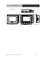
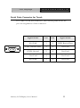
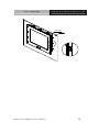
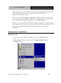
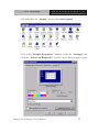
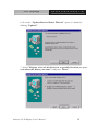
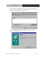
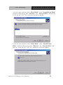
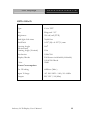
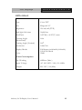
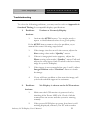
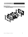
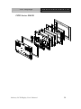
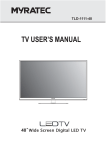
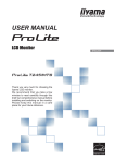
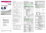
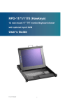
1
LCD Displays
O P D- 2 1 2 A / 2 1 5 A / 2 1 7 A
OPD-212A/215A/217A
Open Frame
Industrial LCD Displays
OPD Series Manual V.2
Oct. 2003
Industry LCD Display User’s Manual
i
LCD Displays
O P D- 2 1 2 A / 2 1 5 A / 2 1 7 A
Copyright Notice
This document is copyrighted 2003, by AAEON Technology In. All rights are
reserved. The original manufacturer reserves the right to make improvements
to the products described in this manual at any time without notice.
No part of this manual may be reproduced, copied, translated, or transmitted
in any form or by any means without the prior written permission of the
original manufacturer. Information provided in this manual is intended to be
accurate and reliable. However, the original manufacturer assumes no
responsibility for its use, nor for any infringements upon the rights of third
parties, which may result from its use.
The material in this document is for product information only and is subject
to change without notice.
Industry LCD Display User’s Manual
1
LCD Displays
O P D- 2 1 2 A / 2 1 5 A / 2 1 7 A
Packing List
The LCD monitor comes with the following standard parts shown as
below. Check and make sure they are included and in good condition.
If anything is missing or damaged, contact the dealer immediately.
1.
Industrial Display Panel x 1 pc
2.
Industrial Display Panel User’s Manual CD-ROM x 1 pc
3.
Power adapter x 1 pc
4.
VGA Cable 1.8 M x 1 pc
5.
Panel Mounting Kits
6.
Screws bag
7.
Adapter cable saddle
8.
Cable. RS-232 (optional)
9.
Waterproof Sponge
It is better for you to keep the carton and the packing materials in
case you might need them for packing or moving in the future.
Industry LCD Display User’s Manual
2
LCD Displays
O P D- 2 1 2 A / 2 1 5 A / 2 1 7 A
Safety & Warranty
1.
Read these safety instructions carefully.
2.
Keep this user's manual for later reference.
3.
Disconnect this equipment from any AC outlet before cleaning. Do
not use liquid or spray detergents for cleaning. Use a damp cloth.
4.
For pluggable equipment, the power outlet must be installed near the
equipment and must be easily accessible.
5.
Keep this equipment away from humidity.
6.
Put this equipment on a reliable surface during installation. Dropping
it or letting it fall could cause damage.
7.
The openings on the enclosure are for air convection. Protect the
equipment from overheating. DO NOT COVER THE OPENINGS.
8.
Make sure the voltage of the power source is correct before
connecting the equipment to the power outlet.
9.
Position the power cord so that people cannot step on it. Do not place
anything over the power cord.
10. All cautions and warnings on the equipment should be noted.
11. If the equipment is not used for a long time, disconnect it from the
power source to avoid damage by transient over-voltage.
12. Never pour any liquid into an opening. This could cause fire or
electrical shock.
13. Never open the equipment. For safety reasons, only qualified service
personnel should open the equipment.
14. If any of the following situations arises, get the equipment checked by
service personnel:
a.
The power cord or plug is damaged.
b.
Liquid has penetrated into the equipment.
c.
The equipment has been exposed to moisture.
Industry LCD Display User’s Manual
3
LCD Displays
15.
O P D- 2 1 2 A / 2 1 5 A / 2 1 7 A
d.
The equipment does not work well, or you cannot get it to
work according to the users manual.
e.
The equipment has been dropped and damaged.
f.
The equipment has obvious signs of breakage.
DO NOT LEAVE THIS EQUIPMENT IN AN ENVIRONMENT
WHERE THE STORAGE TEMPERATURE IS BELOW -20°
C(-4°F) OR ABOVE 60° C (140° F). IT MAY DAMAGE THE
EQUIPMENT.
FCC Safety
This device complies with Part 15 FCC Rules.
Operation is subject to the following two
conditions: (1) this device may not cause harmful
interference, and (2) this device must accept any
interference received including interference that
may cause undesired operation.
Caution:
Danger of explosion if battery is incorrectly replaced. Replace only with the same or
equivalent type recommended by the manufacturer. Dispose of used batteries according to
the manufacturer’s instructions.
Industry LCD Display User’s Manual
4
LCD Displays
O P D- 2 1 2 A / 2 1 5 A / 2 1 7 A
Contents
Copyright Notice ........................................................................................1
Packing List ..................................................................................................2
Safety & Warranty ......................................................................................3
Chapter 1 General Information
Introduction...............................................................................................8
Open Frame Structure Illustration......................................................... 9
Features of Display Panels........................................................................10
General Specifications...............................................................................11
Dimension...................................................................................................13
Waterproof Sponge Position....................................................................15
Chapter 2 Hardware Installation
Before Unpacking.......................................................................................18
Connecting Power..................................................................................... 19
Connecting the Computer.........................................................................20
VGA Port Connector.................................................................................21
Serial Ports Connector for Touch ............................................................22
Panel Mounting....................................... ...................................................23
Rack Mounting (Optional) .................... ...................................................25
Chapter 3 On Screen Display Control
On Screen Display (OSD) Controller......................................................27
Chapter 4 Drivers Installation
Display Driver Installation.........................................................................36
Touchscreen Driver Installation...............................................................46
Industry LCD Display User’s Manual
5
LCD Displays
O P D- 2 1 2 A / 2 1 5 A / 2 1 7 A
Specifications...............................................................................................47
Troubleshooting..........................................................................................51
Exploded Diagram......................................................................................53
Industry LCD Display User’s Manual
6
LCD Displays
O P D- 2 1 2 A / 2 1 5 A / 2 1 7 A
1
Chapter
General
Information
Industry LCD Display User’s Manual
7
LCD Displays
O P D- 2 1 2 A / 2 1 5 A / 2 1 7 A
Introduction
Congratulations on your purchase of the Industry Display Panel
TFT LCD monitor - a marvelous contribution of cutting edge
technology.
The LCD monitor has been designed with serious thoughts to
present the best performance for most applications. Symbol of
elegance, its compact and slim profile is well suited in working
locations where space is at a premium.
The TFT LCD monitor displays sharper, more brilliant, crisper and
flicker-free images. Complying with the power management
regulations of VESA DPMS, the LCD monitor is extremely energy
efficient and a power saver. Plus, the LCD monitor has extremely low
radiation emissions and near zero electromagnetic fields which are
supreme benefits.
Fully compatible with PC system, the LCD monitor provides full
interface for all sorts of related standards. Supported by “Plug &
Play” complying with DDC1/DDC2B, installing the LCD monitor is
absolutely trouble free.
The On Screen Display menu provides user a convenient interface to
make right adjustment for optimum display performance.
Industry LCD Display User’s Manual
8
LCD Displays
O P D- 2 1 2 A / 2 1 5 A / 2 1 7 A
Open Frame Structure Illustration
Industry LCD Display User’s Manual
9
LCD Displays
O P D- 2 1 2 A / 2 1 5 A / 2 1 7 A
Features of Display Panels
This menu provides full range of analog interface LCD panels, which
are 12.1”(SVGA), 15”(XGA) and 17”(SXGA) high-brightness, long
lifetime TFT LCD monitors.
n
Stainless steel open-frame architecture
n
12.1” SVGA (800x600 resolution)
15” XGA (1024x768 resolution)
17” SXGA (1280x1024 resolution) color TFT
LCD display
n
Analog RGB signals directly input with A/D
board interface offering multi-scan function
n
RS-232, Adapter, VGA terminals and AV+S
Video input
n
OSD (On Screen Display) function for display
adjustment
n
Touchscreen (Optional)
n
AC-in /DC-out external power adapter
n
Swivel ARM: VESA 75/100 Standard
n
Aluminum front bezel (Optional)
n
Auto detect NTSC, PAL
n
Adapter holder
Industry LCD Display User’s Manual
10
LCD Displays
O P D- 2 1 2 A / 2 1 5 A / 2 1 7 A
General Specifications
n
Construction:
Stainless steel open-frame architecture
n
Mounting:
Panel mount or Swivel ARM
n
Input signal:
RGB, Composite video, S-Video
n
Control:
OSD (On Screen Display) on the rear panel
n
Power Supply:
external power adapter
n
Dimension:
OPD-212A:
350(W) x 275(H) x 48.7(D) mm
without bezel
366(W) x 291(H) x 49.7(D) mm
with standard bezel
483(W) x 310(H) x 49.7(D) mm
with rack mount bezel
OPD-215A:
428(W) x 320(H) x 53.3(D) mm
without bezel
444(W) x 336(H) x 54.3(D) mm
with standard bezel
483(W) x 354.80(H) x 54.3(D) mm
with rack mount bezel
OPD-217A:
482(W) x 398(H) x 57.2(D) mm
without bezel
483(W) x 399(H) x 58.2(D) mm
with standard bezel
483(W) x 399(H) x 58.2(D) mm
with rack mount bezel
Industry LCD Display User’s Manual
11
LCD Displays
O P D- 2 1 2 A / 2 1 5 A / 2 1 7 A
Net Weight:
n
OPD-212A: 5.5Kg
OPD-215A: 6.5Kg
OPD-217A: 15.36Kg
Touchscreen (Optional)
n
Type: 8-wire or 5-wire. Analog resistive
Resolution:
n
n
Ø
1024x1024 for OPD-212A/OPD-215A
Ø
4096x4096 for OPD-217A
Light transmission:
l
OPD-212/OPD-215: 75%
l
OPD-217: 76% +-2
Controller: RS-232 interface
Environmental Specifications
n
Operating temperature:
0°C to 45°C (32~113°F)
n
Vibration:
5-500Hz, 1G random vibration
n
Shock:
15G peak acceleration (11 msec. Duration)
n
EMI:
FCC / CE Class A
n
Safety:
UL (for OPD-215-E series only)
Industry LCD Display User’s Manual
12
LCD Displays
O P D- 2 1 2 A / 2 1 5 A / 2 1 7 A
Dimensions
483.0
OPD-212A
57.2
310.4
88.9
Unit:mm
366.0
85.7
48.7
88.9
330.0
30.0
255.0
115.0
275.0
75.0
291.0
186.9
75.0
248.4
70.0
100.0
100.0
350.0
Front Bezel Size
70.0
Chassis Cutout Size:333*258 mm
LCD Cutout Size:248.4*186.9 mm
483.0
Unit:mm
354.8
53.3
6.0
428.0
30.0
6.0
59.3
296.0
320.0
79.0
75.0
336.0
75.0
79.0
444.0
90.3
402.0
101.6
76.2
101.6
OPD-215A
88.0
Front Bezel Size
Industry LCD Display User’s Manual
120.0
120.0
88.0
Cutout Size:405*299 mm
13
LCD Displays
O P D- 2 1 2 A / 2 1 5 A / 2 1 7 A
57.2
94.2
446.0
OPD-217A
6.0
Front Bezel Size
Industry LCD Display User’s Manual
362.0
85.0
85.0
399.0
85.0
101.5
75.0
483.0
398.0
101.6
85.0
6.0
120.6
Unit:mm
90.0
90.0
90.0
75.0
482.0
Cutout Size:449*365 mm
14
LCD Displays
O P D- 2 1 2 A / 2 1 5 A / 2 1 7 A
Waterproof Sponge Position
Inside sponge:
a. Tear off the protection paper on the self-adhesive side
of the inside sponge.
b. Stick the sponge on the recessed area of the Aluminum
bezel or customer’s own bezel.
Front Bezel
Back Side
Adhesive
Inner Sponge
Industry LCD Display User’s Manual
15
LCD Displays
O P D- 2 1 2 A / 2 1 5 A / 2 1 7 A
Outer sponge:
Press to close the outer sponge to the edge of the Panel PC.
Outer Sponge
Front Bezel
Sponge with adhesive
Industry LCD Display User’s Manual
16
LCD Displays
O P D- 2 1 2 A / 2 1 5 A / 2 1 7 A
2
Chapter
Hardware
Installation
Industry LCD Display User’s Manual
17
LCD Displays
O P D- 2 1 2 A / 2 1 5 A / 2 1 7 A
Before Unpacking
It is very important to locate the LCD monitor in a suitable
environment.
§
The surface for placing the LCD monitor should be stable and
level.
§
Make sure the place has good ventilation, and out of direct
sunlight; away form sources of excessive dust, dirt, heat, water,
moisture and vibration.
§
Convenience for connecting the LCD monitor to the related
facilities should be well considered too.
Industry LCD Display User’s Manual
18
LCD Displays
O P D- 2 1 2 A / 2 1 5 A / 2 1 7 A
Connecting Power
To power on the LCD monitor, use the provided AC-DC adapter and
the power cord to connect to the power output socket of the monitor.
Fasten the connections securely.
A ”Surge Protection” device plugged between the AC-DC adapter
and the wall outlet is recommended to prevent the effects of sudden
current variations from reaching the LCD monitor. The sudden
peaks of electricity may harm the LCD monitor.
Industry LCD Display User’s Manual
19
LCD Displays
O P D- 2 1 2 A / 2 1 5 A / 2 1 7 A
Connecting to the Computer
n
Turn off the computer and the LCD monitor before connecting
them.
n
Use the Monitor-to-PC VGA cable to connect the LCD monitor to
your computer. The cable heads are the same on either side.
n
Fasten the connections securely.
Industry LCD Display User’s Manual
20
LCD Displays
O P D- 2 1 2 A / 2 1 5 A / 2 1 7 A
VGA Port Connector
It is a DB-15 VGA connector. The following table shows the
pin-out assignments of this connector.
Signal Name
Pin #
Pin #
Signal Name
Red
1
2
Green
Blue
3
4
N.C.
GND
5
6
GND
GND
7
8
GND
N.C.
9
10
GND
N.C.
11
12
SDA
HSYNC
13
14
VSYNC
SCL
15
Industry LCD Display User’s Manual
21
LCD Displays
O P D- 2 1 2 A / 2 1 5 A / 2 1 7 A
Serial Ports Connector for Touch
It is a DB-9 COM Port connector. The following table shows the
pin-out assignments of this connector.
Signal Name
Pin
Pin
Signal Name
Not Used
1
2
RXD, Receive Data
TXD, Transmit Data
3
4
Not Used
GND, Ground
5
8
Not Used
Not Used
4
9
Not Used
Not Used
5
10
Not Used
Industry LCD Display User’s Manual
22
LCD Displays
O P D- 2 1 2 A / 2 1 5 A / 2 1 7 A
Panel Mounting
These display panels can be placed on a shelf or table, or mounted
onto the wall. To mount them onto the wall, you need the mounting
brackets, which you will find in the accessory box. Follow the steps
described below:
•
Slide the display panel into cutout on the wall.
•
Tighten the brackets until the display panel is firmly secured to
the wall.
SPONGE
PANEL
MOUNT BRACKET
Industry LCD Display User’s Manual
23
LCD Displays
O P D- 2 1 2 A / 2 1 5 A / 2 1 7 A
Sponge
Panel
Industry LCD Display User’s Manual
24
LCD Displays
O P D- 2 1 2 A / 2 1 5 A / 2 1 7 A
Rack Mounting (Optional)
Optional 19” rack mount frame is also available for all models.
Industry LCD Display User’s Manual
25
LCD Displays
O P D- 2 1 2 A / 2 1 5 A / 2 1 7 A
3
Chapter
On Screen
Display Control
Industry LCD Display User’s Manual
26
LCD Displays
O P D- 2 1 2 A / 2 1 5 A / 2 1 7 A
On Screen Display (OSD) Controller
The LCD monitor is very easy and simple to operate. There are five
controls below on the rear panel. You can see their respective
indicators.
AUTO
To auto adjust image position, pixel clock
and phase. Whenever there is flicker
happens, always press the AUTO button
first.
The setting value will be automatically
adjusted correctly and saved.
Notice:
The OPD series displays were designed
to provide the best quality in 60-75MHz
VGA frequency range. We recommend
keeping the screen refresh rate within
the range in order to obtain the
optimum quality.
Industry LCD Display User’s Manual
27
LCD Displays
MENU
O P D- 2 1 2 A / 2 1 5 A / 2 1 7 A
Menu
To activate the OSD Menu, press the
Button. When locating an item you like to
adjust in the OSD Menu, press to bring up
the corresponding sub-menu for options.
Increase / Moving UP Button
To move the locating cursor forward in the
OSD Menu, press UP button. To increase
the value while adjusting a parameter, press
the
button.
Decrease / Moving DOWN Button
To move the locating cursor backward in
the OSD Menu, press the
button. To
decrease the value while adjusting a
parameter, press
button.
Power Switch
Push up the Power Switch to turn on/off
the LCD monitor backlight and the power
LED will light up Green/Red.
Industry LCD Display User’s Manual
28
LCD Displays
O P D- 2 1 2 A / 2 1 5 A / 2 1 7 A
Display Menu
There are twelve options in the OSD Menu. Press the Menu
button to choose the items you would like to adjust.
<Main Menu>
ADB100A AAEON Inc
InputSource
PIP Enable
AutoTune
Brightness
Contrast
Color
Quality
Position
Language
Recall
Save Exit
Cancel Exit
<InputSource>
VGA
AVideo
SVideo
Return
Select PC or Composite Video Input Source
Industry LCD Display User’s Manual
29
LCD Displays
O P D- 2 1 2 A / 2 1 5 A / 2 1 7 A
To scroll through items and locate for adjustment in each page,
presses Menu button to select. The display will automatically shut
down when there’s no input source been selected.
Source input diagram
DC-in Jack
VGA
Video-in
S-Video Touch screen
(AVideo)
(SVideo)
<PIP enable>
AVideo
SVideo
PIP Off
Return
Picture-in-picture enable function allows you to view screen with
VGA input and Avideo or SVideo sources at same time. Use up
and down arrows to select major viewing source. Press Menu to
enter your selection. The second input source window will be
displayed on the bottom right corner.
Combinations are as follows:
VGA (main source) + Avideo (2nd source)
VGA (main source) + SVideo (2nd source)
Press Return to previous menu.
Industry LCD Display User’s Manual
30
LCD Displays
O P D- 2 1 2 A / 2 1 5 A / 2 1 7 A
<AutoTune>
To automatically tune the display to the best image size, position and
phase.
<Brightness>
Brightness
0
To adjust the brightness level of the image, using up and down
arrows
button.
<Contrast >
Contrast
35
To adjust the difference between the light and dark areas, using up and
down arrows button.
Industry LCD Display User’s Manual
31
LCD Displays
O P D- 2 1 2 A / 2 1 5 A / 2 1 7 A
<Color>
9300
7500
6550
User
Return
9300: To set the color temperature to 9300K.
7500: To set the color temperature to 7500K.
6550: To set the color temperature to 6550K.
User: To set the RGB color temperature by user defines.
Press Return to previous menu.
<Quality>
ADV. TUNE
Size
Phase
Text/Gfx
Sharpness
Return
ADV. TUNE: To further tuning the image size, phase, and
sharpness. Please make use of this feature whenever the VGA
input has been changed.
Size: To expand the image of full screen or to shrink the image to
normal (1piexl to 1piexl).
Industry LCD Display User’s Manual
32
LCD Displays
O P D- 2 1 2 A / 2 1 5 A / 2 1 7 A
Phase: To adjusts the phase of pixel frequency. Use the function
when there is a pixel noise.
Text/Gfx: To exchange to the text or graphic mode (Not for
Windows OS).
Sharpness: To adjust sharpness of the image.
Press Return to previous menu.
<Position>
Image Pos.
OSD Pos.
Speed En.
Speed Adj.
Return
Image Pos.: To adjust the Horizontal & Vertical position of the
image.
OSD Pos: To adjust the Horizontal & Vertical position of the OSD
Menu.
Speed En. and Speed Adjust: To adjust OSD Menu display speed.
Press Return to previous menu.
<Language>
Only English is available.
Industry LCD Display User’s Manual
33
LCD Displays
O P D- 2 1 2 A / 2 1 5 A / 2 1 7 A
<Recall>
When you run the function, the monitor will be setting to the last
status of the saving value.
<Save Exit>
To save all setting value and exit.
<Cancel Exit>
To cancel all setting value and exit.
Hotkey Control
The Hot key control allows you to instant activate frequent use
function without browsing OSD menu.
+ AUTO
After power on, press the AUTO button
for 3 – 5 seconds, The monitor will reset the
parameters to default value.
Industry LCD Display User’s Manual
34
LCD Displays
O P D- 2 1 2 A / 2 1 5 A / 2 1 7 A
4
Chapter
Drivers
Installation
Industry LCD Display User’s Manual
35
LCD Displays
O P D- 2 1 2 A / 2 1 5 A / 2 1 7 A
The first time you start Windows with a new monitor, the system will
detect OPD display and automatically detect and install the
Plug-and-Play device driver.
However, manual installation might be needed when your video card
does not comply with DDC1/DDCB2 standard, the system can only
detect Windows Default Monitor, not the OPD displays.
When your system detects Windows Default Monitor or cannot detect
the display at all, follows the step-by-step installation guide below. The
drivers for manual installation are provided in the supporting
CD-ROM.
Display Driver Installation
Windows 98
1. Insert the supporting CD-ROM into your CD-ROM Driver.
2. Click “Start” button and look for “Control Panel” under
“Settings” menu.
Industry LCD Display User’s Manual
36
LCD Displays
O P D- 2 1 2 A / 2 1 5 A / 2 1 7 A
3. Double click the “display” icon in the control panel.
4. From the “Display Properties” window, select the “settings” tab.
Click the “Advanced Properties” button on the bottom right corner.
Industry LCD Display User’s Manual
37
LCD Displays
O P D- 2 1 2 A / 2 1 5 A / 2 1 7 A
5. Select the “Monitor” tab. Click the “Change” button in the top
right corner.
Industry LCD Display User’s Manual
38
LCD Displays
O P D- 2 1 2 A / 2 1 5 A / 2 1 7 A
6. Now the “Update Device Driver Wizard” opens. Confirm by
clicking “Update”.
7. Select "Display a list of all drivers in a specific location, so you
can select the driver you want." and press "Next".
Industry LCD Display User’s Manual
39
LCD Displays
O P D- 2 1 2 A / 2 1 5 A / 2 1 7 A
8. Now click the “Have disk” button in the bottom right corner.
Another window appears, select the “Browse” button. Look for the
“.inf” file extension for drivers update.
9. Close “Update Device Driver Wizard” by click “Finish” to
complete the installation.
Industry LCD Display User’s Manual
40
LCD Displays
O P D- 2 1 2 A / 2 1 5 A / 2 1 7 A
Windows 2000
1.
Repeat steps 1 – 4 as in Windows 98 setup.
2.
Select the “Monitor” tab. Click the “Properties” button.
Industry LCD Display User’s Manual
41
LCD Displays
O P D- 2 1 2 A / 2 1 5 A / 2 1 7 A
6. Select “Driver” tab then click “Update Driver”.
Industry LCD Display User’s Manual
42
LCD Displays
O P D- 2 1 2 A / 2 1 5 A / 2 1 7 A
7. The “Upgrade Device Driver Wizard” will pop up. Then Click
“Next”.
8. The “Upgrade Device Driver Wizard” will pop up. Then Click
“Next”.
Industry LCD Display User’s Manual
43
LCD Displays
O P D- 2 1 2 A / 2 1 5 A / 2 1 7 A
9. In the next window, click “Have Disk”, then “Install From Disk”
window will pop up, click “Browse", the “Located File” will pop up.
Look for the “.inf” file extension for drivers update
10. In the next window, click “Have Disk”, then “Install From
Disk” window will pop up, click “Browse", the “Located File” will
pop up. Look for the “.inf” file extension for drivers update.
Industry LCD Display User’s Manual
44
LCD Displays
O P D- 2 1 2 A / 2 1 5 A / 2 1 7 A
11. The “Digital Signature Not Found” window will appear, click
“Yes”, then click “Finish”.
12. Now the new drivers are installed to your computer.
Industry LCD Display User’s Manual
45
LCD Displays
O P D- 2 1 2 A / 2 1 5 A / 2 1 7 A
Touchscreen Driver Installation
For Touchscreen installation please refer to the excel file :
ReadMe_All-Prods-Touch-list.xls to find out your match touscreen
type and follow the installation guide in respective folders.
For the following models, please use the Combo Toolkit to install.
OPD-215AT-D1
OPD-215AT-D2
OPD-215ABT-D1
OPD-215ABT-D2
OPD-215ART-D1
OPD-215ART-D2
OPD-217AT-D1
OPD-217AT-E1
OPD-217ABT-D1
OPD-217ABT-E1
OPD-217ART-D1
OPD-217ART-E1
Industry LCD Display User’s Manual
46
LCD Displays
O P D- 2 1 2 A / 2 1 5 A / 2 1 7 A
Specifications
OPD-212A
Panel
Type
Color TFT
Size
Diagonal “12.1”
Brightness
250 cd/m2 (TYP.)
Back light MTBF
50,000 hrs
Pixel Pitch
0.3075(H) x 0.3075(V) mm
Viewing Angle (Horizontal)
1200
Viewing Angle (Vertical)
900
Resolution
800x600
Display Modes
Full Screen in 640x480, 800x600
Mode
256K
Color
Power Consumption
On- Working
60Watts (Max.)
Input Voltage
AC 100-240V~1.8A, 50~60Hz
Output
DC 12V / 5A(Max)
Industry LCD Display User’s Manual
47
LCD Displays
O P D- 2 1 2 A / 2 1 5 A / 2 1 7 A
OPD-215A-D
Panel
Type
Color TFT
Size
Diagonal “15”
Brightness
250 cd/m2 (TYP.)
Back light Life-time
30,000 hrs
Pixel Pitch
0.297(H) x 0.297(V) mm
Viewing Angle
(Horizontal)
Viewing Angle (Vertical)
1600
Resolution
1024x768
Display Modes
Full Screen in 640x480, 800x600,
1024x768 Mode
256K
Color
1500
Power Consumption
On- Working
60Watts (Max.)
Input Voltage
AC 100-240V~1.8A, 50~60Hz
Output
DC 12V / 5A(Max)
Industry LCD Display User’s Manual
48
LCD Displays
O P D- 2 1 2 A / 2 1 5 A / 2 1 7 A
OPD-215A-E
Panel
Type
Color TFT
Size
Diagonal 15”
Brightness
250 cd/m2 (TYP.)
Back light Life-time
50,000 hrs
Pixel Pitch
0.297(H) x 0.297(V) mm
Viewing Angle
(Horizontal)
Viewing Angle (Vertical)
1600
Resolution
1024x768
Display Modes
Full Screen in 640x480, 800x600,
1024x768 Mode
256K
Color
1600
Power Consumption
On- Working
60Watts (Max.)
Input Voltage
AC 100-240V~1.8A, 50~60Hz
Output
DC 12V / 5A(Max)
Industry LCD Display User’s Manual
49
LCD Displays
O P D- 2 1 2 A / 2 1 5 A / 2 1 7 A
OPD-217A
Panel
Type
Color TFT
Size
Diagonal 17”
Brightness
260cd/m2 (TYP.)
Back light MTBF
40,000hrs
Contrast Ratio
400: 1
Pixel Pitch
0.264(H) x 0.264(V) mm
Viewing Angle
(Horizontal)
Viewing Angle (Vertical)
1600
Resolution
1280x1024
Display Modes
Full Screen in 640x480, 800x600,
1024x768, 1280x1024 Mode
256K
Color
1600
Power Consumption
On- Working
60Watts (Max.)
Input Voltage
AC 100-240V~1.8A, 50~60Hz
Output
DC 12V / 5A(Max)
Industry LCD Display User’s Manual
50
LCD Displays
O P D- 2 1 2 A / 2 1 5 A / 2 1 7 A
Troubleshooting
To solve the following problems, you may need to refer to Appendix A
Standard Timing for compatible display specifications.
1.
Problem:
Unclear or Unsteady Display
Actions:
1.
Activate the AUTO button. You might need to
repeat to find balanced values for a good quality.
If the AUTO button cannot solve the problem, try to
manual fine tune following steps below:
2.
1.
If the image size does not fit the screen, adjust the
Size setting value under “Quality” menu.
2.
If there is image pixel noise appears, adjust the
Phase setting value under “Quality” menu. Pull and
adjust the value bar to find out what is the best clarity
range for your LCD display.
3.
If the image is not centered after step 1 and 2, adjust
Image Position under “Position” menu to center
the image.
4.
If you still have problem to fine-tune the image, call
your local technical support for assistance.
Problem:
No Display is shown on the LCD monitor.
Actions:
1.
2.
Make sure the LCD monitor is powered on by
checking if the Power LED is lit. Check if all the
connections are secure and the system is running
correctly.
If the power LED lights up green, but there is still
nothing displayed; connect your PC with another
Industry LCD Display User’s Manual
51
LCD Displays
O P D- 2 1 2 A / 2 1 5 A / 2 1 7 A
external monitor. If your PC works properly with
that monitor, then it is possible that the VGA card
timing of the system may be outside the LCD
monitor’s synchronous range. You may need a
qualified technician for help.
3.
Problem:
display.
“Not Supported Mode” is shown on the
Action:
This could be a mistake you made in the OSD menu
while choosing the INPUT SOURCE: RGB or
VEDIO. Or, it is possible that you have chosen a
timing that is outside the LCD monitor’s
synchronous range. Recall the factory default values
may help to bring the screen back to normal.
4.
Problem: The LCD monitor does not work properly
under Windows, but it functions all right in DOS
mode.
Action:
Make sure the display mode you choose in Windows
matches the LCD monitor.
Industry LCD Display User’s Manual
52
LCD Displays
O P D- 2 1 2 A / 2 1 5 A / 2 1 7 A
Exploded Diagram
OPD Series FRONT
Industry LCD Display User’s Manual
53
LCD Displays
O P D- 2 1 2 A / 2 1 5 A / 2 1 7 A
OPD Series BACK
Industry LCD Display User’s Manual
54