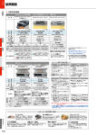
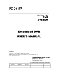
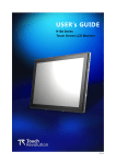
1
AMB-232A/223A/255A/280A Series
Analog Display Panel
Version 1.5
Industrial Display Panel
Analog Display Panel for Industrial Automation
User’s Manual
History
Ø
Version 1.5
Emphasis AUTO ADJUST feature in OSD control on page 27.
Industry Display Panel User’s Manual
CE/FCC Certificate
AMB-232A/232AT CE Report
Industry Display Panel User’s Manual
ii
CE/FCC Certificate
AMB-232A/232AT FCC Report
Industry Display Panel User’s Manual
iii
CE/FCC Certificate
AMB-223A/223AT CE Report
Industry Display Panel User’s Manual
iv
CE/FCC Certificate
AMB-223A/223AT FCC Test Report
Industry Display Panel User’s Manual
v
CE/FCC Certificate
AMB-255A/AMB-255AT CE Report
Industry Display Panel User’s Manual
vi
CE/FCC Certificate
AMB-255A/AMB-255AT FCC Report
Industry Display Panel User’s Manual
vii
Safety & Warranty
Safety & Warranty
1. Read these safety instructions carefully.
2. Keep this user's manual for later reference.
3.
Disconnect this equipment from any AC outlet before cleaning. Do not use liquid or
spray detergents for cleaning. Use a damp cloth.
4.
For pluggable equipment, the power outlet must be installed near the equipment and
must be easily accessible.
5.
Keep this equipment away from humidity.
6. Put this equipment on a reliable surface during installation. Dropping it or letting it
fall could cause damage.
7.
The openings on the enclosure are for air convection. Protect the equipment from
overheating. DO NOT COVER THE OPENINGS.
8. Make sure the voltage of the power source is correct before connecting the
equipment to the power outlet.
9.
Position the power cord so that people cannot step on it. Do not place anything over
the power cord.
10. All cautions and warnings on the equipment should be noted.
11. If the equipment is not used for a long time, disconnect it from the power source to
avoid damage by transient over-voltage.
12. Never pour any liquid into an opening. This could cause fire or electrical shock.
13. Never open the equipment. For safety reasons, only qualified service personnel
should open the equipment.
14. If any of the following situations arises, get the equipment checked by service
personnel:
a. The power cord or plug is damaged.
b.
Liquid has penetrated into the equipment.
c.
The equipment has been exposed to moisture.
d.
The equipment does not work well, or you cannot get it to work according to the users
manual.
e.
The equipment has been dropped and damaged.
f.
The equipment has obvious signs of breakage.
15.
DO NOT LEAVE THIS EQUIPMENT IN AN UNCONTROLLED
ENVIRONMENT WHERE THE STORAGE TEMPERATURE IS BELOW -20° C
(-4°F) OR ABOVE 60° C (140° F). IT MAY DAMAGE THE EQUIPMENT.
Industry Display Panel User’s Manual
Contents
Contents
AMB-232A/232AT CE Report .............................................................................................. ii
AMB-232A/232AT FCC Report........................................................................................... iii
AMB-223A/223AT CE Report ............................................................................................. iv
AMB-223A/223AT FCC Test Report.................................................................................... v
AMB-255A/AMB-255AT CE Report................................................................................... vi
AMB-255A/AMB-255AT FCC Report ............................................................................... vii
Chapter1
General Information......................................................................................11
General Information................................................................................................................... 2
1.1.
Introduction................................................................................................................ 2
1.2.
Packing List ................................................................................................................ 3
1.3.
Features of Display Panels......................................................................................... 4
1.3.1.
AMB-232A .......................................................................................................... 4
1.3.2.
AMB-223A .......................................................................................................... 4
1.3.3.
AMB-255A .......................................................................................................... 5
1.3.4.
AMB-280A .......................................................................................................... 6
1.4.
General........................................................................................................................ 7
1.4.1.
AMB-232A .......................................................................................................... 7
1.4.2.
AMB-223A .......................................................................................................... 7
1.4.3.
AMB-255A .......................................................................................................... 7
1.4.4.
AMB-280A .......................................................................................................... 7
1.5.
Touchscreen (Optional).............................................................................................. 8
1.6.
Environment ............................................................................................................... 8
1.7.
Order Information..................................................................................................... 9
1.8.
Dimensions ................................................................................................................ 10
1.8.1.
AMB-232A ........................................................................................................ 10
1.8.2.
AMB-223A ........................................................................................................ 10
1.8.3.
AMB-255A .........................................................................................................11
1.8.4.
AMB-255AR.......................................................................................................11
1.8.5.
AMB-280A ........................................................................................................ 12
Chapter 2
Installation .................................................................................................... 13
Installation ................................................................................................................................ 14
Industry Display Panel User’s Manual
9
Contents
2.1.
Before Unpacking..................................................................................................... 14
2.2.
Terminals on the Rear Panel................................................................................... 15
AMB-232A, AMB-223A, AMB-255A.............................................................................. 15
AMB-280A ........................................................................................................................ 15
2.3.
Connecting Power .................................................................................................... 16
2.4.
Connecting the Computer ....................................................................................... 17
2.5.
Panel Mounting ........................................................................................................ 18
2.6.
Desk Top (Optional) ................................................................................................ 19
2.7.
Wall Mounting (Optional) ....................................................................................... 20
2.8.
Rack Mounting (Optional) ...................................................................................... 21
Chapter 3
User Controls ................................................................................................ 22
User Control .............................................................................................................................. 23
3.1.
OSD Controller......................................................................................................... 23
3.2.
On Screen Display [OSD] ........................................................................................ 24
APPENDIX A............................................................................................................................ 29
Specifications ............................................................................................................................ 30
I.
AMB-232A .................................................................................................................... 30
II.
AMB-223A ................................................................................................................ 31
III.
AMB-255A ................................................................................................................ 32
IV.
AMB-280A ................................................................................................................ 33
Standard Timing ....................................................................................................................... 34
Power Management System...................................................................................................... 35
Troubleshooting ........................................................................................................................ 36
APPENDIX B............................................................................................................................ 37
Exploded diagram ..................................................................................................................... 38
I.
AMB-232A .................................................................................................................... 38
II.
AMB-223A ................................................................................................................ 38
III.
AMB-255................................................................................................................... 39
IV.
AMB-280A ................................................................................................................ 39
Industry Display Panel User’s Manual
10
Contents
1
Chapter1 General Information
Chapter1
General Information___________________________________________11
General Information_________________________________________________________ 2
1.1.
Introduction _______________________________________________________ 2
1.2.
Packing List _______________________________________________________ 3
1.3.
Features of Display Panels____________________________________________ 4
1.4.
General ___________________________________________________________ 7
1.5.
Touchscreen (Optional) ______________________________________________ 8
1.6.
Environment _______________________________________________________ 8
1.7.
Order Information__________________________________________________ 9
1.8.
Dimensions _______________________________________________________ 10
Industry Display Panel User’s Manual
11
Chapter 1 General Information
General Information
1.1.
Introduction
Congratulations on your purchase of the Industry Display Panel TFT LCD
monitor - a marvelous contribution of cutting edge technology.
The LCD monitor has been designed with serious thoughts to present the best
performance for most applications. Symbol of elegance, its compact and slim
profile is well suited in working locations where space is at a premium.
The TFT LCD monitor displays sharper, more brilliant, crisper and flickerfree images. Complying with the power management regulations of VESA
DPMS, the LCD monitor is extremely energy efficient and a power saver.
Plus, the LCD monitor has extremely low radiation emissions and near zero
electromagnetic fields which are supreme benefits.
Fully compatible with PC and Mac, the LCD monitor provides full interface
for all sorts of related standards. Supported by “Plug & Play” complying with
DDC1/DDC2B, installing the LCD monitor is absolutely troubled free.
The On Screen Display menu provides the user a convenient interface to make
the right adjustment for optimum display performance.
Industry Display Panel User’s Manual
2
Chapter 1 General Information
1.2.
Packing List
The LCD monitor comes with the following standard parts shown as below.
Check and make sure they are included and in good condition. If anything is
missing or damaged, contact the dealer immediately.
1.
2.
3.
4.
5.
6.
Industrial Display Panel x 1 pc
Industrial Display Panel User’s Manual Disk x 1 pc
AC to DC power adaptor x 1 pc
VGA Cable 1.2 M x 1 pc
Panel Mounting Kits
Screws beg
With Touch Screen Optional
1. Touch Manual x 1 pc
2. Touch Pen x 1 pc
3. Drive Disk for Windows 95/98 v3.1
4. Drive Disk for Windows NT 4.0 v3.1
5. Drive Disk for DOS v7.06B & WIN 3.1 v3.01
To comply with the FCC & CE regulations, video cables
included with the LCD monitor are ferrite-loaded.
It is better for you to keep the carton and the packing materials in case you
might need them for packing or moving in the future.
Industry Display Panel User’s Manual
3
Chapter 1 General Information
1.3.
Features of Display Panels
This menu provides full ranging analog interface LCD panels, which are
10.4”(VGA), 12.1”(SVGA), 15”(XGA) and 18.1”(SXGA) hi-brightness,
long lifetime TFT LCD monitors.
1.3.1. AMB-232A
n
n
n
n
n
n
n
n
n
n
n
n
n
n
n
n
Heavy-duty stain-less steel chassis & NEMA 4/12 & IP 65
aluminum alloy front panel
10.4” VGA (640x480 resolution) color TFT LCD display
Analog RGB signals directly input with A/D board interface
offering multi-scan function
RS-232, Adapter, RGB terminals and AV input
OSD controller on the front panel
Touchscreen (Optional)
Using standard VGA card
DC/12V external power adapter
Hi-brightness 200 cd / m2, Long-life time (20,000 hrs)
Panel mount
Wall mount: VESA 75 Standard (Optional)
Desk top: VESA 75 Standard (Optional)
Cable saddle
Cable length: up to 20 meters
Auto detect NTSC, PAL and Secam
Adapter holder
1.3.2. AMB-223A
n
n
n
n
n
n
Heavy-duty stain-less steel chassis & NEMA 4/12 & IP 65
aluminum alloy front panel
12.1” SVGA (800x600 resolution) color TFT LCD display
Analog RGB signals directly input with A/D board interface
offering multi-scan function
RS-232, Adapter, RGB terminals and AV input
OSD controller on the front panel
Touchscreen (Optional)
Industry Display Panel User’s Manual
4
Chapter 1 General Information
n
n
n
n
n
n
n
n
n
n
n
Using standard VGA card
DC/12V external power adapter
Hi-brightness 250 cd / m2, Long-life time (25,000 hrs)
Panel mount
Wall mount: VESA 75 Standard (Optional)
Desk top: VESA 75 Standard (Optional)
Cable saddle
Cable length: up to 20 meters
Auto detect NTSC, PAL and Secam
Adapter holder
19” Rack mount panel (Optional)
1.3.3. AMB-255A
n
n
n
n
n
n
n
n
n
n
n
n
n
n
n
n
n
Heavy-duty stain-less steel chassis & NEMA 4/12 & IP 65
aluminum alloy front panel
15” XGA (1024x768 resolution) color TFT LCD display
Analog RGB signals directly input with A/D board interface
offering multi-scan function
RS-232, Adapter, RGB terminals and AV input
OSD controller on the front panel
Touchscreen (Optional)
Using standard VGA card
DC/12V external power adapter
Hi-brightness 250 cd / m2, Long-life time (25,000 hrs)
Panel mount
Wall mount: VESA 75 Standard (Optional)
Desk top: VESA 75 Standard (Optional)
Cable saddle
Cable length: up to 20 meters
Auto detect NTSC, PAL and Secam
Adapter holder
19” Rack mount panel (Optional)
Industry Display Panel User’s Manual
5
Chapter 1 General Information
1.3.4. AMB-280A
n
n
n
n
n
n
n
n
n
n
n
n
n
n
n
n
n
Heavy-duty stain-less steel chassis & NEMA 4/12 & IP 65
aluminum alloy front panel
18.1” SXGA (1280x1024 resolution) color TFT LCD display
Analog RGB signals directly input with A/D board interface
offering multi-scan function
RS-232, Adapter, RGB terminals, AV input and S Video
OSD controller on the front panel
Touchscreen (Optional)
Using standard VGA card
DC/12V external power adapter
Hi-brightness 235 cd / m2, Long-life time (25,000 hrs)
Panel mount
Wall mount: VESA 75 Standard (Optional)
Desk top: VESA 75 Standard (Optional)
Cable saddle
Cable length: up to 20 meters
Auto detect NTSC, PAL and Secam
Adapter holder
19” Rack mount panel
Industry Display Panel User’s Manual
6
Chapter 1 General Information
1.4.
General
1.4.1. AMB-232A
n
Construction: Heavy-duty stain-less steel chassis &
aluminum alloy front panel
n
Dimension: 288.2(W) x 195.2(H) x 49(D) mm
n
Gross Weight:
6Kg
1.4.2. AMB-223A
n
Construction: Heavy-duty stain-less steel chassis &
aluminum alloy front panel
n
Dimension: 339(W) x 341(H) x 230(D) mm
n
Gross Weight:
7.5Kg
1.4.3. AMB-255A
n
Construction: Heavy-duty stain-less steel chassis &
aluminum alloy front panel
n
Dimension: 420(W) x 300(H) x 55(D) mm
n
Gross Weight:
10.3Kgs
1.4.4. AMB-280A
n
Construction: Heavy-duty stain-less steel chassis &
aluminum alloy front panel
n
Dimension: 450.5(W) x 383(H) x 55(D) mm
n
Gross Weight:
13Kgs
Industry Display Panel User’s Manual
7
Chapter 1 General Information
1.5.
Touchscreen (Optional)
n
n
n
n
n
n
n
1.6.
Type: 4/8-wire, analog resistive
Resolution: Continuous
Light transmission: 72% (surface meets 4H, ASTM-D-336392A standard.)
Operating pressure: 30-45 grams for finger, 10 grams for stylus
pen. Contact bounce< 10ms
Controller: RS-232 interface
Power consumption: +5V @200mA
OS support: MS DOS, Windows 3.1, Windows 95, Windows 98,
Windows NT.
Environment
n
n
n
n
n
n
n
n
Operating temperature: 0°C to 50°C
Storage temperature: -20°C to 60°C
Relative humidity:
5 to 95%, non-condensing
Altitude:
10,000 ft. (3000 meters)
Vibration: 5 to 17Hz, 0.1” double-amplitude displacement 17 to
500Hz, 1.5G peak to peak
Shock:
10G peak acceleration (11 msec. Duration)
Safety:
meets UL / CSA / TUV
EMI:
FCC / VDE Class A
Industry Display Panel User’s Manual
8
Chapter 1 General Information
1.7.
Order Information
n
n
n
n
n
n
n
n
AMB-232A:
With 10.4” VGA color LCD display
Includes: External power adapter and 1.2m VGA extension cable
AMB-232A-T (Optional touchscreen)
AMB-223A:
With 12.1” SVGA color LCD display
Includes: External power adapter and 1.2m VGA extension cable
AMB-223A-T (Optional touchscreen)
AMB-255A:
With 15” XGA color LCD display
Includes: External power adapter and 1.2m VGA extension cable
AMB-255A-T (Optional touchscreen)
AMB-280A:
With 18.1” SXGA color LCD display
Includes: External power adapter and 1.2m VGA extension cable
AMB-280A-T (Optional touchscreen)
Industry Display Panel User’s Manual
9
Chapter 1 General Information
1.8.
Dimensions
Unit: mm
1.8.1. AMB-232A
1.8.2. AMB-223A
Industry Display Panel User’s Manual
10
Chapter 1 General Information
1.8.3. AMB-255A
1.8.4. AMB-255AR
Industry Display Panel User’s Manual
11
Chapter 1 General Information
1.8.5. AMB-280A
SOURCE MENU
UP
DOWN
POWER
SOURCE
Industry Display Panel User’s Manual
MENU UP
DOWN
POWER
12
Chapter 2 Installation
2
Chapter 2 Installation
Chapter 2
Installation .................................................................................................... 13
Installation ................................................................................................................................ 14
2.1.
Before Unpacking..................................................................................................... 14
2.2.
Terminals on the Rear Panel................................................................................... 15
AMB-232A, AMB-223A, AMB-255A.............................................................................. 15
AMB-280A ........................................................................................................................ 15
2.3.
Connecting Power .................................................................................................... 16
2.4.
Connecting the Computer ....................................................................................... 17
2.5.
Panel Mounting ........................................................................................................ 18
2.6.
Desk Top (Optional) ................................................................................................ 19
2.7.
Wall Mounting (Optional) ....................................................................................... 20
2.8.
Rack Mounting (Optional) ...................................................................................... 21
Industry Display Panel User’s Manual
13
Chapter 2 Installation
Installation
2.1.
Before Unpacking
It is very important to locate the LCD monitor in a suitable
environment.
n
The surface for placing the LCD monitor should be stable and
level.
n
Make sure the place has good ventilation, is out of direct
unlighted, away form sources of excessive dust, dirt, heat, water,
moisture and vibration.
n
Convenience for connecting the LCD monitor to the related
n
Facilities should be well considered too.
Industry Display Panel User’s Manual
14
Chapter 2 Installation
2.2.
Terminals on the Rear Panel
AMB-232A, AMB-223A, AMB-255A
AMB-280A
Industry Display Panel User’s Manual
15
Chapter 2 Installation
2.3.
Connecting Power
To supply the LCD monitor with power, use the provided AC-DC adapter and
the power cord to connect to the power output socket of the computer. Fasten
the connections securely.
Ps: If your computer is not equipped with such a power out put socket for
the monitor, you may apply a power cord to connect to the provided
AC-DC adapter and then plug it into the wall outlet. The plug should
meet the electrical requirements in your country.
A ”Surge Protection” device plugged between the AC-DC adapter and the
wall outlet is recommended to prevent the effects of sudden current variations
from reaching the LCD monitor. The sudden peaks of electricity may do harm
to the LCD monitor.
Industry Display Panel User’s Manual
16
Chapter 2 Installation
2.4.
Connecting the Computer
n
Turn off the computer and the LCD monitor before
Connecting them.
n
Use the Monitor-to PC signal cable to connect the LCD monitor
to the VGA port in your computer. The cable heads are the same
on either side.
n
Fasten the connections securely.
Industry Display Panel User’s Manual
17
Chapter 2 Installation
2.5.
Panel Mounting
These display panels can be placed on a shelf or table, or mounted onto a control
panel. To mount them onto a control panel you need a kind of mounting kit, which
you will find in the accessory box. Take the mounting steps described here below:
1.
2.
3.
Set the display panel within the aperture in your control panel
Slide the mounting kits into the slots on the chassis cover
Tighten the bolt in the kits until the display panel is firmly secured to the
control
PANEL MOUNTING
Industry Display Panel User’s Manual
18
Chapter 2 Installation
2.6.
Desk Top (Optional)
Important Information
1. You can adjust the tightness of arm rotation by turning #4 knobs clockwise.
2. You can adjust the tightness of display rotation by turning # 11 hex set
screws clockwise or counter-clockwise by attached 3 mm hex key wrench.
3. Normally, you do not need adjust #14 knobs. If it is necessary to do so, you
may turn the #14 knobs clockwise or counter-clockwise to adjust the
friction for a most soft and smooth lifting operation of your LCD arm, but
do not turn #14 knobs off.
4. You can counter-balanced adjust the tilt of your display for 45 degrees
upward or 25 degrees downward. Hex key wrenches are attached for
adjusting screw tightness when it is necessary.
5. Your LCD display is pivot adjustable
6. Cable can be organized inside the arm housing by removing and inserting
#3 plastic cover.
7. Do not screw the #13 fasteners off.
Industry Display Panel User’s Manual
19
Chapter 2 Installation
2.7.
Wall Mounting (Optional)
Important information
1. You can adjust the tightness of monitor rotation by turning #11 set screws
Clockwise or counter-clockwise by the attached 3 mm hex key wrench.
2. Monitor tilt adjustment range is 45 degrees up or 25 degrees down. You are
suggested to adjust #16 hex screw by the attached hex keys to a best tilt
friction, when you first use of your LCD arm.
3. Your LCD monitor is portrait/landscape pivot adjustable 360 degrees.
Industry Display Panel User’s Manual
20
Chapter 2 Installation
2.8.
Rack Mounting (Optional)
Users can select different front panels for 19” rack mounting on
12.1”(AMB-223A) and 15” (AMB-255A) LCD panels.
Industry Display Panel User’s Manual
21
Chapter 3 User Control
3
Chapter 3 User Controls
Chapter 3
User Controls ................................................................................................ 22
User Controls ............................................................................................................................ 23
3.1.
OSD Controller......................................................................................................... 23
3.2.
On Screen Display [OSD] ........................................................................................ 24
Industry Display Panel User’s Manual
22
Chapter 3 User Control
User Control
3.1.
OSD Controller
The LCD monitor is very easy and simple to operate. There are five
controls below the front panel. You can see their respective indicators on
the front.
SOURCE
MENU
UP
DOWN
POWER
SOURCE
MENU
UP
DOWN
POWER
PC & Composite Video Input Source change select
To scroll through items and locate them for adjustment in
each page of the OSD menu, presses select button
Menu
To activate the OSD menu, press the Button. When locating
an item you like to adjust in the OSD menu, press to bring up
the corresponding sub-menu for options.
Increase / Moving Down Button / Enter Button
To move the locating cursor forward in the OSD menu, press
UP button. To increase the value while adjusting a parameter,
press the UP button.
Decrease / Moving Up Button
To move the locating cursor backward in the OSD menu,
press the DOWN button. To decrease the value while
adjusting a parameter, press DOWN button.
Power Switch
Push up the Power Switch to turn on the LCD monitor
backlight and the power LED will light up green.
Industry Display Panel User’s Manual
23
Chapter 3 User Control
3.2.
On Screen Display [OSD]
There are eight options in the OSD menu. Press the Menu button to
Choose the items you would like to adjust.
<Menu>
BASIC SETTING
POSITION
SCREEN SETTING
AUTO ADJUST
MENU SETTING
RECALL
ALL RESET
EXIT
<BASIC SETTING>
BRIGHTNESS 128
CONTRAST
128
COLOR CONTROL
EXIT
BRIGHTNESS: To adjust the black color level of the image using UP and
DOWN button.
CONTRAST: To adjust the white color level of the image using UP and
DOWN button.
.
Industry Display Panel User’s Manual
24
Chapter 3 User Control
COLOR CONTROL:
COLOR 1
COLOR 2
COLDR 3
USER
EXIT
COLOR1: To setting the color temperature of the image
to 9300 K.
COLOR2: To setting the color temperature of the image
to 6500 K.
COLOR3: To setting the color temperature of the image
to 5000 K.
USER:
To setting the RGB color of the image by user
define.
EXIT:
Return previous menu.
EXIT (Under BASIC SETTING): Return previous menu.
Industry Display Panel User’s Manual
25
Chapter 3 User Control
<POSITION>
PHASE
10
H-SIZE
32
H-POSITION
32
V-POSITION
32
EXIT
PHASE: To adjust the noise of the image.
H-SIZE: To adjust the Horizontal size of the image.
H-POSITION: To adjust Horizontal position of the image.
V-POSITION: To adjust the Vertical position of the image.
EXIT: Return previous menu.
<SCREEN SETTING>
GRAPHIC/TEXT
EXPANSION
SMART SCALE
EXIT
GRAPHIC/TEXT: To exchange the 640X400(60Hz)/720X350(60Hz).
(Not for Windows OS)
EXPANSION: To expansion the image of full screen to shrink the
image to normal (1piexl to 1piexl). (Not for 640 x 840)
SMART SCALE: To adjust the image to interpolation.
EXIT: Return previous menu.
Industry Display Panel User’s Manual
26
Chapter 3 User Control
<AUTO ADJUST>
AUTO ADJUST
AUTO TRANCKING
AUTO POSITION
EXIT
AUTO ADJUST: To auto tune the tracking & position. Please make use of
this feature whenever the VGA input has been changed.
AUTO TRACKING: To auto tune the H-SIZE & PHASE of the image.
ATUO POSITION: To auto tune the Horizontal & Vertical position of
the image.
EXIT: Return previous menu.
<MENU SETTING>
LANGUAGE
MENU POSITION
DISPLAY INFO
FW VERSION
EXIT
LANGUAGE: To select the English or Japanese of the OSD
MENU POSITION: To adjust the Horizontal & Vertical position
of the OSD
DISPLAY INFO: To show the PC input Horizontal & Vertical
Frequency & Resolution of the image.
FW VERSION: To show the version of the system BIOS.
EXIT: Return previous menu.
Industry Display Panel User’s Manual
27
Chapter 3 User Control
<RECALL>
When you run the function, the monitor will be setting to last
status of the saving value.
<ALL RESET>
Recover the BIOS default setting.
<EXIT>
To close the OSD & saving all setting value.
Industry Display Panel User’s Manual
28
Appendix A
A
APPENDIX A
APPENDIX A............................................................................................................................ 29
Specifications ............................................................................................................................ 30
I.
AMB-232A .................................................................................................................... 30
II.
AMB-223A ................................................................................................................ 31
III.
AMB-255A ................................................................................................................ 32
IV.
AMB-280A ................................................................................................................ 33
Standard Timing ....................................................................................................................... 34
Power Management System...................................................................................................... 35
Troubleshooting ........................................................................................................................ 36
Industry Display Panel User’s Manual
29
Appendix A
Specifications
I. AMB-232A
Panel
Type
Size
Brightness
Back light Life-time
Contrast Ratio
Pixel Pitch
Viewing Angle (Horizontal)
Viewing Angle (Vertical)
Resolution
Display Modes
Color
Input Signal
Compatibility
Power Management
Color TFT
Diagonal 10.4"
200 cd/m2
20,000
150: 1
0.33x0.33mm
900
500
640x480
Full Screen in 640x480 mode
262K
Analog RGB (0.7 V p-p, 75ohms)
VGA, SVGA, XGA, IBM PC, MacII
VESA DPMS
Power Consumption
On- Working
On- Standby
Input Voltage
Output
Safety & EMI
48Watts (Max.)
4Watts
AC 90~264V, 50~60Hz
DC 12V / 3A
FCC-A, CE
Industry Display Panel User’s Manual
30
Appendix A
II. AMB-223A
Panel
Type
Size
Brightness
Back light Life-time
Contrast Ratio
Pixel Pitch
Viewing Angle (Horizontal)
Viewing Angle (Vertical)
Resolution
Display Modes
Color
Input Signal
Compatibility
Power Management
Color TFT
Diagonal 12.1”
250 cd/m2
25,000 hrs
250: 1
0.3075(H) x 0.3075(V) mm
1200
1000
800x600
Full Screen in 640x480, 800x600mode
262K
Analog RGB (0.7 V p-p, 75ohms)
VGA, SVGA, XGA, IBM PC, MacII
VESA DPMS
Power Consumption
On- Working
On- Standby
Input Voltage
Output
48Watts (Max.)
4Watts
AC 90~264V, 50~60Hz
DC 12V / 3A
Industry Display Panel User’s Manual
31
Appendix A
III.
AMB-255A
Panel
Type
Size
Brightness
Back light Life-time
Contrast Ratio
Pixel Pitch
Viewing Angle (Horizontal)
Viewing Angle (Vertical)
Resolution
Display Modes
Color
Input Signal
Compatibility
Power Management
Color TFT
Diagonal 15”
250 cd/m2
25,000 hrs
300:1
0.279(H) x 0.279(V) mm
1600
1600
1024x768
Full Screen in 640x480, 800x600, 1024x768 mode
262K
Analog RGB (0.7 V p-p, 75ohms)
VGA, SVGA, XGA, IBM PC, MacII
VESA DPMS
Power Consumption
On- Working
On- Standby
Input Voltage
Output
48Watts (Max.)
4Watts
AC 90~264V, 50~60Hz
DC 12V / 3A
Industry Display Panel User’s Manual
32
Appendix A
IV.
AMB-280A
Panel
Type
Size
Brightness
Back light Life-time
Contrast Ratio
Pixel Pitch
Viewing Angle (Horizontal)
Viewing Angle (Vertical)
Resolution
Display Modes
Color
Input Signal
Compatibility
Power Management
Color TFT
Diagonal 18.1”
235 cd/m2
25,000 hrs
300: 1
0.2805(H) x 0.2805(V) mm
1600
1600
1280x1024
Full Screen in 640x480, 800x600, 1024x768,
1280x1024 mode
16M
Analog RGB (0.7 V p-p, 75ohms)
VGA, SVGA, XGA, IBM PC, MacII
VESA DPMS
Power Consumption
On- Working
On- Standby
Input Voltage
Output
60Watts (Max.)
4Watts
AC 90~264V, 50~60Hz
DC 12V / 3A
Industry Display Panel User’s Manual
33
Appendix A
Standard Timing
RGB Input Format:
MODE
TEXT
VGA
SVGA
XGA
MAC
Supported Analog RGB Input Formats
Resolution
Horizontal
Vertical
(KHz)
(Hz)
640X350
31.469
70.087
720X350
31.469
70.087
720X400
31.469
70.087
640X400
31.469
70.087
640X350
37.861
85.08
720X350
37.861
85.08
720X400
37.861
85.08
640X400
37.927
85.039
640X400
24.828
56.40
640X480
31.468
59.94
640X480
37.861
72.809
640X480
37.5
75
640X480
43.269
85.008
640X480
45
90
800X600
35.156
56.26
800X600
37.879
60.317
800X600
48.077
72.188
800X600
46.875
75
800X600
53.674
85.061
1024X768
48.363
60.004
1024X768
56.069
70.069
1024X768
58.088
72.98
1024X768
60.023
75.029
1024X768
68.677
84.997
1024X768(I)
35.522
43.479
640X480
35
66.67
832X624
49.729
74.5
Industry Display Panel User’s Manual
Polarity
(H/V)
(+/-)
(+/-)
(-/+)
(-/+)
(+/-)
(+/-)
(+/-)
(-/+)
(-/-)
(-/-)
(-/-)
(-/-)
(-/-)
(+/+)
(+/+)
(+/+)
(+/+)
(+/+)
(+/+)
(-/-)
(-/-)
(+/+)
(+/+)
(+/+)
(+/-)
(-/-)
34
Appendix A
Power Management System
The LCD monitor complies with the power management regulations of VESA
DPMS(version 1.0p). It is provided with two phases of power saving modes
by detecting the horizontal or vertical synchronous signal.
When the system is in the power saving mode or an incorrect timing is
detected, the monitor screen will be blank and the power LED will flash
orange.
Status
Power
Consumption
On – Working
On – Standby
48 watts (max.)
less than 4 watts
Industry Display Panel User’s Manual
Time to
Resume
3 seconds
LED Color
Green
Orange
35
Appendix A
Troubleshooting
To solve the following problems, you may need to refer to Appendix A
Standard Timing for compatible display specifications.
• Problem:
Unclear or Unsteady Display
Actions:
1. Change to the Windows’s SHUT DOWN screen.
2. Activate the OSD menu.
3. Adjust the setting of frequency to stabilize the display.
4. Adjust the setting of phase to clarify the image.
5. You might need to repeat steps 3 and 4 to find balanced values for
a best quality.
• Problem:
No Display is shown on the LCD monitor.
Actions:
1. Make sure the LCD monitor is powered on by checking if the
Power LED is lit. Check if all the connections are secure and the
system is running correctly.
2. If the power LED lights up green, but there is still nothing
displayed; connect your PC with another external monitor. If
your PC works properly with that monitor, then it is possible that
the VGA card timing of the system may be outside the LCD
monitor’s synchronous range. You may need a qualified
technician for help.
•
Problem:
“Not Supported Mode” is shown on the display.
Action: This could be a mistake you made in the OSD menu while
choosing the INPUT SOURCE: RGB or VEDIO. Or, it is
possible that you have chosen a timing that is outside the LCD
monitor’s synchronous range. Recall the factory default values
may help to bring the screen back to normal.
•
Problem:
The LCD monitor does not work properly under
Windows, but it functions all right in DOS mode.
Action: Make sure the display mode you choose in Windows matches the
LCD monitor.
Industry Display Panel User’s Manual
36
Appendix B
B
APPENDIX B
Industry Display Panel User’s Manual
37
Appendix B
Exploded diagram
I. AMB-232A
II. AMB-223A
Industry Display Panel User’s Manual
38
Appendix B
III.
AMB-255
IV.
AMB-280A
Industry Display Panel User’s Manual
39