1
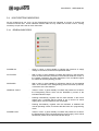
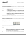
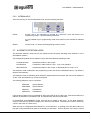
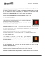
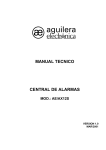
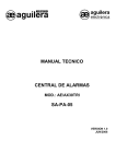
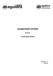
EXTINGUISHING CONTROL PANEL
PX2 SERIES
AE/PX2
AE/SA-PX2
AE/94-PX2
USER MANUAL
VERSION 1.0
APR/2007
PX2 SERIES - USER MANUAL
CONTENT
PAGE
1
INTRODUCTION. ...................................................................................................... 3
1.1
1.2
1.3
1.4
1.5
1.6
2
PURPOSE OF THE MANUAL. ........................................................................................ 3
REMARKS....................................................................................................................... 3
WARNINGS AND PRECAUTIONS. ................................................................................ 3
APPROVALS................................................................................................................... 3
VERIFICATION OF THE PANEL..................................................................................... 4
MATERIAL INCLUDED IN THE PACKING. .................................................................... 4
INSTALLATION......................................................................................................... 5
2.1
2.2
2.3
SIZE................................................................................................................................. 5
POSITIONING THE PANEL. ........................................................................................... 6
CASING ANCHORING. ................................................................................................... 6
3
CHARACTERISTICS:................................................................................................ 9
4
CONNECTION. ....................................................................................................... 11
4.1
4.2
4.3
MAINS SUPPLY ............................................................................................................ 11
EXTERNAL CONNECTIONS ........................................................................................ 12
AE/SA-PX2 PANEL CONNECTION TO ALGORITMIC LOOP...................................... 16
4.3.1
4.4
4.4.1
4.5
5
CODING ................................................................................................................................16
AE/94-PX2 PANEL CONNECTION TO 3-WIRE ALGORITMIC LOOP ......................... 17
CODING ................................................................................................................................17
AE/PX2RA AUXILIARY RELAY CARD. ........................................................................ 18
OPERATION ........................................................................................................... 19
5.1
5.2
5.3
5.4
AUTOMATIC AND MANUAL MODES........................................................................... 20
DISABLED MODE ......................................................................................................... 21
ACCESS LEVELS. ........................................................................................................ 21
LIGHT-EMITTING INDICATORS................................................................................... 22
5.4.1
5.4.2
5.4.3
5.4.4
5.4.5
5.5
5.6
GENERAL INDICATORS ......................................................................................................22
INDIVIDUAL LIGHT-EMITTING INDICATORS. ....................................................................23
INDIVIDUAL INTERNAL LIGHT-EMITTING INDICATORS. .................................................24
OPERATING MODE INDICATORS. .....................................................................................25
ALPHANUMERIC DISPLAY..................................................................................................25
OPERATING MODE SELECTION KEY. ....................................................................... 26
OPERATING KEYS. ...................................................................................................... 26
5.6.1
5.6.2
FRONT KEYS........................................................................................................................26
INTERNAL KEYS. .................................................................................................................27
5.7 AUTOMATIC DETECTION LOOPS. ............................................................................. 27
5.8 RELEASE PUSHBUTTON. ........................................................................................... 28
5.9 HOLD PUSHBUTTON. .................................................................................................. 28
5.10
FLOW DETECTOR. ................................................................................................... 29
5.11
WEIGHT CONTROL OR PRESSURE SXITCH. ........................................................ 29
5.12
SOUNDER. ................................................................................................................ 29
5.13
EXTINGUISHING. ...................................................................................................... 30
5.14
EXTINGUISHING SIGN BOARD RELEASED. .......................................................... 30
5.15
AUXILIARY SUPPLY OUTPUT.................................................................................. 31
Ae-man-327-0.0 v1.0
1
AGUILERA ELECTRONICA
PX2 SERIES - USER MANUAL
5.16
5.17
6
PROGRAMMING PARAMETERS........................................................................... 33
6.1
6.2
6.3
6.4
7
POWER SUPPLY UNIT AND BATTERY CHARGER. ............................................... 31
REPEATER RELAYS................................................................................................. 32
DETECTION LOOP MODE. .......................................................................................... 34
EXTINGUISHING DELAY TIME.................................................................................... 34
EXTENDED DISCHARGE............................................................................................. 35
RESET HOLD TIME. ..................................................................................................... 35
TECHNICAL CHARACTERISTICS. ........................................................................ 37
Ae-man-327-0.0 v1.0
2
AGUILERA ELECTRONICA
PX2 SERIES - USER MANUAL
1 INTRODUCTION.
1.1
PURPOSE OF THE MANUAL.
The purpose of this manual is to furnish the user with a full description on recommended procedures and
technical details for carrying out the installation and commissioning of the PX2 SERIES Extinguishing
Control Panel.
The procedures described in this manual include advice and warnings to guide the user in the adoption of
safe and methodical working practices during installation and commissioning.
1.2
REMARKS.
•
•
1.3
The following manual is only valid for the wiring and commissioning of the PX2 Series
Extinguishing Control Panel. For other panel models, consult the pertinent manual.
The manufacturer reserves the right to change, modify or correct the information without prior
notice.
WARNINGS AND PRECAUTIONS.
L
The installer of the Extinguishing Control Panel and of the equipment that form the Fire Detection
System must be an authorized installer trained in handling the Panel, and familiar with the regulations in
force.
Before connecting any item of equipment, verify that the Panel supply voltage is disconnected.
The user should read this manual and fully understand its content before beginning any task related with
the Extinguishing Control Panel. If doubts exist on any of the matters described in the manual, consult
the supplier before beginning the installation and commissioning.
1.4
APPROVALS.
The control panel has been designed according to:
•
The EN54-2 and EN54-4 standards, regarding both mandatory functions and some optional ones with
requirements.
•
Electromagnetic compatibility with the Community Directive EEC/89/336 and amendments EEC/92/31
and EEC/93/68.
•
Compatibility with the Community Low Voltage Directive EEC/73/23 and amendment EEC/93/68.
Some of the panel functions can be configured to make it more effective and enhance the possibilities of
the equipment, but they are not contemplated by the EN54 regulations, and therefore, if used, would not
comply with this standard.
When some type of connection or configuration can be carried out that may not comply with the
regulation, this will be indicated, with a brief explanation of the requirements set by the EN54 standard.
Ae-man-327-0.0 v1.0
3
AGUILERA ELECTRONICA
PX2 SERIES - USER MANUAL
1.5
VERIFICATION OF THE PANEL.
It is important to conduct a visual inspection to check that the equipment supplied has not suffered any
damage before beginning its installation. If any anomaly is observed, IT SHOULD NOT BE INSTALLED;
contact the supplier.
1.6
MATERIAL INCLUDED IN THE PACKING.
In the crate, together with the Panel, you will find the following material accompanying the equipment:
1.
2.
3.
4.
5.
Installation Manual: This manual. Ae-man-327-0.0
Cable kit for emergency batteries with terminal protector included.
Set of keys for the access level selector on the front.
End-of-line resistances connected.
2 diodes for connection of the solenoid valve.
Ae-man-327-0.0 v1.0
4
AGUILERA ELECTRONICA
PX2 SERIES - USER MANUAL
2 INSTALLATION.
2.1
SIZE.
The panel is housed in a metal cabinet 273 mm high X 320 mm wide X 123 mm deep.
It is recommended to leave a free space of at least 100 mm around the whole box to allow correct
ventilation of the equipment.
The dimensions are shown in the following diagram:
26,0 mm
103,0 mm
20,0 mm
123,0 mm
103 mm
320,0 mm
CPU
273,0 mm
POWER
SUPPLY
BATTERY 12V
MAX. 7Ah
BATTERY 12V
MAX. 7Ah
103,0 mm
20,0 mm
Ae-man-327-0.0 v1.0
5
AGUILERA ELECTRONICA
PX2 SERIES - USER MANUAL
2.2
POSITIONING THE PANEL.
The Control Panel should be installed in an appropriate place, in an area that is monitored and protected,
and meets a number of requirements:
•
The ambient operating temperature remains between +5ºC and +35ºC.
•
The relative humidity is between 5% and 90%.
•
The panel will be mounted on a wall so that it allows the screen to be seen clearly and easy
access to the operating keys. The height above the floor should be selected so that the control
keys are at eye level (at 1.6 m approximately).
•
The panel should not be located in places exposed to high levels of humidity.
•
The panel should not be located in places exposed to vibration or impact.
•
The panel should not be located in places where access is blocked to the internal components
and the wiring connections.
For the correct operation of the equipment, it is necessary to respect the indicated distances to achieve
correct ventilation and avoid overheating of the equipment.
2.3
CASING ANCHORING.
L
The AE/PX2 Extinguishing Control Panel can weigh more than 9 kg with the batteries fitted. When
fastening the casing to the wall, use appropriate fasteners, and reinforce the wall if necessary.
Prepare the necessary holes for the cable entry into the panel:
•
If entry is foreseen through the top or from underneath, open the holes by means of a sharp blow
on the hole stamping. Take care not to hit outside. Only make the perforations necessary.
•
If cable entry is foreseen through the rear, remove the back plate. To do this, use cutting pliers to
remove the side fasteners of the plate.
CUT
REAR CABLE
ENTRY PLATE
Fasten the panel casing to the wall in an appropriate place, using the three existing holes of 6mm in
diameter.
Ae-man-327-0.0 v1.0
6
AGUILERA ELECTRONICA
PX2 SERIES - USER MANUAL
The following figure shows the anchorage marks on the casing.
320,0 mm
43,0 mm
273,3 mm
180,3 mm
50,0 mm
75,0 mm
Ae-man-327-0.0 v1.0
170,0 mm
7
75,0 mm
AGUILERA ELECTRONICA
PX2 SERIES - USER MANUAL
Ae-man-327-0.0 v1.0
8
AGUILERA ELECTRONICA
PX2 SERIES - USER MANUAL
3 CHARACTERISTICS:
The PX2 SERIES of extinguishing control panels are microprocessor-controlled alarm stations, designed
according to the European EN 12094-1:2003 standard, comprising:
•
Two monitored areas with dual conventional detection and three different operating modes:
• Crossed detection:
• Dual detection in one of the loops.
•
Mixed detection through crossed detection or dual detection in either of the two loops.
•
Monitored circuit with pushbutton for remote release.
•
Release pushbutton on the panel front, with protective cover and indicator lamp.
•
Monitored circuit with pushbutton for remote hold.
•
Hold pushbutton on the panel front, with protective cover and indicator lamp.
•
Monitored circuit for flow detector.
•
Monitored circuit for weight control or pressure switch.
•
Monitored evacuation area.
•
Monitored extinguishing area with programmable delay time.
•
Control of programmable deluge time.
•
Output for extinguishing released board, monitored.
•
Control of reset hold time after release has taken place.
•
Power supply unit and battery charger, with mains voltage control, batteries, feed, battery
charging and auxiliary output.
•
Outputs for repeater relays.
•
Possibility of connection in 2- and 3-wire algorithmic systems of Aguilera Electrónica by means of
interface module mounted on the same mother board.
•
Selection of automatic, manual and disabled operating mode, and access level by means of
safety key.
•
Internal and external indicator lamps, as well as an alphanumeric display for presentation of
release time and menu functions.
•
Easy and intuitive handling and programming by means of three external and two internal keys.
•
Programmed values stored in EEPROM memory.
Ae-man-327-0.0 v1.0
9
AGUILERA ELECTRONICA
PX2 SERIES - USER MANUAL
Ae-man-327-0.0 v1.0
10
AGUILERA ELECTRONICA
PX2 SERIES - USER MANUAL
4 CONNECTION.
4.1
MAINS SUPPLY
L Before making any connection, make sure there is no voltage on the cables and this is cut off at the
corresponding electric switchboard.
The Extinguishing Control Panel can be fed from a voltage source of 110 to 250Vac, 50/60Hz.
The conduits and the mains wiring should be kept separate from the rest of the panel wiring.
For feeding in the power cables, the hole on the extreme right should be used.
Pass the cable through an appropriate cable gland for the cable type.
The connection to the three-position connector is carried out as shown in the following figure:
•
•
•
The phase cable (brown) should be connected to terminal L.
The neutral cable (blue or black) should be connected to terminal N.
The earth cable (green - yellow) should be connected to terminal T.
The connector has a 1-Amp fuse.
FUS
1A 250V~
L
N
POWER
SUPPLY
The supply for the fire control equipment must have a differential for independent protection with a safety
fuse of 230Vac / 5A or higher. The cross section of the power supply wiring must not be less than 0.75
mm2.
Ae-man-327-0.0 v1.0
11
AGUILERA ELECTRONICA
PX2 SERIES - USER MANUAL
4.2
EXTERNAL CONNECTIONS
The connections of the Extinguishing Panel are made on the terminal blocks located on the mother board.
Any incorrect connection of the panel lines can cause it to be damaged.
The terminal allocation is the following:
DETECTOR LOOP 1: CONNECTOR J6
1. Connect the loop positive, + BUC.1, of the PX2 extinguishing panel in the positive of the detector
socket.
2. Connect the loop negative, - BUC.1, of the PX2 extinguishing panel in the negative of the detector
socket.
3. Proceed to connect the detectors as shown in the following figure.
4. Remove the end of line resistor that is connected on the panel connection blocks and transfer it to the
end of the detector line.
Ae-man-327-0.0 v1.0
12
AGUILERA ELECTRONICA
PX2 SERIES - USER MANUAL
DETECTOR LOOP 2: CONNECTOR J7
This loop will only be connected when the operating mode of the panel is Crossed Detection or Mixed
Detection.
The connection is similar to that indicated in loop 1.
+ LOOP
E.O.L.
2K7 1/2W
- LOOP
REMOTE
INDICATOR
REMOTE
INDICATOR
+24Vdc
AUXILIAR
POWER SUPPLY
REMOTE RELEASE DEVICE: CONNECTOR J8
1. Connect the release positive, +P.DIS, of the PX2 extinguishing panel to the NC (normally closed)
terminal of the remote release device.
2. Connect the release negative, -P.DIS, of the PX2
extinguishing panel to the NA (normally open)
RELEASE PUSHBUTTON
terminal of the remote release device.
AE/V-PD1
3. Connect the load resistance of 1K 1/2W (brown black - red) supplied across the C (common) and NC
contacts in the device.
4. Connect the end of line resistance of 2K7 1/2W (red
– purple - red) across the NA and NC contacts of the
device. This resistance is connected on the release
terminals of the PX2 extinguishing panel.
NA
NC
C
FROM
EXTINGUISHING PANEL
P.DIS
E.O.L.
2K7 1/2W
1K
1W
NA
NC
C
+
-
NOTE: If several device switches are connected in
parallel, only connect the end of line resistance on the last one.
REMOTE HOLD PUSHBUTTON: CONNECTOR J9
1. Connect the hold-extinguishing positive, +P.BLQ, of the PX2 extinguishing panel to the NC (normally
closed) terminal of the remote hold pushbutton.
2. Connect the hold-extinguishing negative, -P.BLQ, of
HOLD/STOP PUSHBUTTON
the PX2 extinguishing panel to the NA (normally open)
AE/V-PB1
terminal of the remote hold pushbutton.
3. Connect the load resistance of 1K 1/2W (brown black - red) supplied across the C (common) and NC
contacts in the pushbutton switch.
4. Connect the end of line resistance of 2K7 1/2W (red –
purple - red) across the NA and NC contacts of the
pushbutton switch. This resistance is connected on
the hold terminals of the PX2 extinguishing panel.
Ae-man-327-0.0 v1.0
13
NA
NC
C
FROM
EXTINGUISHING PANEL
P.BLQ
E.O.L..
2K7 1/2W
1K
1W
NA
NC
C
+
-
AGUILERA ELECTRONICA
PX2 SERIES - USER MANUAL
NOTE: If several pushbutton switches are connected in parallel, only connect the line-end resistance
on the last one.
FLOW DETECTOR: CONNECTOR J10
1. Connect the flow detector positive, +DET-F, of the PX2 extinguishing panel to the NC (normally
closed) terminal of the flow detector.
2. Connect the flow detector negative, -DET-F, of the PX2 extinguishing panel to the NA (normally open)
terminal of the flow detector.
3. Connect the load resistance of 1K 1/2W (brown - black - red) across the C (common) and NC
contacts of the flow detector.
4. Connect the end of line resistance of 2K7 1/2W (red – purple - red) across the NA and NC contacts of
the flow detector. This resistance is connected on the flow detector terminals of the PX2
extinguishing panel.
WEIGHT CONTROL: CONNECTOR J11
1. Connect the weight control positive, +CTRL.P, of the PX2 extinguishing panel to the NC (normally
closed) terminal of the weight control.
2. Connect the weight control negative, -CTRL.P, of the PX2 extinguishing panel to the NA (normally
open) terminal of the weight control.
3. Connect the load resistance of 1K 1/2W (brown - black - red) across the C (common) and NC
contacts of the weight control.
4. Connect the line-end resistance of 2K7 1/2W (red – purple - red) across the NA and NC contacts of
the weight control. This resistance is connected on the weight control terminals of the PX2
extinguishing panel.
NOTE: If the intention is to connect with a weight control device of AGUILERA ELECTRONICA
AEX/SBC, connect the extinguishing panel to the AEX/APX2 adapter unit. This unit has the load and end
of line resistances incorporated. Read the manual before installing.
MONITORED SOUNDER OUTPUT: CONNECTOR J12
1. Connect the evacuation output positive, +EVC., of the PX2 extinguishing panel to the positive of the
evacuation bell or sounder.
2. Connect the evacuation output negative, -EVC., of the PX2 extinguishing panel to the negative of the
evacuation bell or sounder.
3. Connect the end of line resistance of 2K7 1/2W (red – purple - red) across the positive and negative
contacts of the bell or sounder. This resistance is connected across the evacuation terminals of the
PX2 extinguishing panel.
SOUNDER
OUTPUT
Ae-man-327-0.0 v1.0
E.O.L.
2K7 1/2W
14
AGUILERA ELECTRONICA
PX2 SERIES - USER MANUAL
NOTE: The alarm device, sounder, bell, siren, etc., should be fitted with an internal diode that
gives polarity to the power supply. If it is not present, it is necessary to insert a type 1N4001
diode or similar.
* The sounders supplied by Aguilera Electrónica incorporate the diode internally, so there is no
need to mount them.
EXTINGUISHING RELEASED SIGN BOARD: CONNECTOR J13
1. Connect the positive of the extinguishing released board, +C.DIS., of the PX2 extinguishing panel to
the positive of the extinguishing sign board.
2. Connect the negative of the extinguishing released board, -C.DIS., of the PX2 extinguishing panel to
the negative of the extinguishing sign board.
EXTINGUISHING OUTPUT: CONNECTOR J14
1. Connect the extinguishing positive, +EXTIN., of the PX2 extinguishing panel in series with a 1N4001
diode or similar, as shown in the figure. Connect the diode cathode to the positive of the solenoid
valve.
2. Connect the extinguishing negative, -EXTIN., of the PX2 extinguishing panel to the negative of the
solenoid valve.
EXTINGUISHING
OUTPUT
SOLENOID
NOTE: Another diode should be mounted in parallel with the solenoid valve coil to avoid the return of
current peaks that can damage the Extinguishing Panel.
These diodes should be mounted on the actual solenoid valve.
AUXILIARY SUPPLY OUTPUT: CONNECTOR J15
1. + USO: Output of +24Vdc /500mA
2. - USO: Common negative output of the power supply
Ae-man-327-0.0 v1.0
15
AGUILERA ELECTRONICA
PX2 SERIES - USER MANUAL
BATTERIES: CONNECTOR J16
Connect as follows.
CPU
NEGATIVE
POSITIVE
NEGATIVE
POSITIVE
BATTERY 12V
MAX. 7Ah
4.3
BATTERY 12V
MAX. 7Ah
AE/SA-PX2 PANEL CONNECTION TO ALGORITMIC LOOP
If the extinguishing panel is integrated in an installation controlled by a 2-wire Algorithmic System FireControl Panel, the connection to the algorithmic loop is made through the J5 terminal located at the top
part of the mother board.
ALGORITMIC LOOP CONNECTION
AE/SA-IPX2 INTERFACE
The contact assignment is the following:
V
Positive loop
G
Common negative
For correct operation, it is necessary for the AE/SA-IPX2 interface module to be mounted on the J2 and
J3 connectors.
4.3.1
CODING
The AE/SA-PX2 extinguishing panel has to be coded with a number that corresponds to its
personalisation. The recording of the panel numbering can be carried out from:
Ae-man-327-0.0 v1.0
16
AGUILERA ELECTRONICA
PX2 SERIES - USER MANUAL
1. AE/SA-PRG manual address programmer. For this connect the output of the programmer for
programming modules to the input terminal of the algorithmic loop J5. To carry out the
programming process, see the programmer’s manual for its coding.
2. Algorithmic Panel. See operating manual of the algorithmic panel for its coding.
Program a number between 1 and 125 as corresponds for its personalization.
System the panel occupies a single position inside the algorithmic loop.
For the Algorithmic
The unit identification number, as well as the operational evidence, is stored in EEPROM memory.
Before connecting the module to the algorithmic loop, verify the coding is correct.
NOTE: The AE/SA-IPX2 interface will not communicate with the Fire Control Panel if the extinguishing
panel does not have a mains supply or batteries.
4.4
AE/94-PX2 PANEL CONNECTION TO 3-WIRE ALGORITMIC LOOP
If the extinguishing panel is integrated in an installation controlled by a 3-wire Algorithmic System FireControl Panel, the connection to the algorithmic loop is made through the J5 terminal located at the top
part of the mother board.
ALGORITMIC LOOP CONNECTION
3 WIRES
ON
1
AE/94-IPX2 INTERFACE
EDG
2 3 4
5 6
7
8
MODULE CODING
The contact assignment is the following:
C
Communications
V
24V supply
G
Common negative
For correct operation, it is necessary for the AE/94-IPX2 interface module to be mounted on the J2 and
J3 connectors.
4.4.1
CODING
All algorithmic equipment must be coded with a number as corresponds to its personalization. This
coding is carried out in binary, through the dilswitch located in the AE/94-IPX2 interface and programming
a code number that will be between 1 and 125.
Ae-man-327-0.0 v1.0
17
AGUILERA ELECTRONICA
PX2 SERIES - USER MANUAL
Before connecting the module to the algorithmic loop, verify the coding is correct.
Once the extinction panel has been connected, check it communicates correctly with the main analogical
panel. If this is not the case, make sure the code of the panel corresponds to that of its personalisation
and check the wiring to the analogical loop.
4.5
AE/PX2RA AUXILIARY RELAY CARD.
OPTIONAL CARD
The auxiliary relay card provides voltage-free-contact outputs for the repeating states of the Extinguishing
Panel, according to the EN 12094-1:2003 standard.
The J1 connector has to be inserted in the J4 connector of the mother board, and later secured to the
casing by means of four screws.
The terminal assignment is the following:
J2 Relay in Alert or Pre-Trip State
NC
C
NA
Contact normally closed
Common contact
Contact normally open
J3 Relay in Tripped State
NC
C
NA
Contact normally closed
Common contact
Contact normally open
J4 Relay in Fault State
NC
C
NA
Contact normally closed
Common contact
Contact normally open
J5 Relay in Not Automatic state
(It is activated when the operating key is in
Manual or Disabled mode)
NC
C
NA
Ae-man-327-0.0 v1.0
18
Contact normally closed
Common contact
Contact normally open
AGUILERA ELECTRONICA
PX2 SERIES - USER MANUAL
5 OPERATION
The Extinguishing Panel has three different operating modes: Automatic, Manual and Disabled.
EN 12094-1
ACTIVATED
FAULT
POWER ON
DETECTION ZONE 1
ACTIVATED
DETECTION ZONE 2
RELEASED
MANUAL RELEASE
GENERAL FAULT
FLOW CONTROL
AUTOMATIC
MANUAL
RELEASE
DISABLED
SOUNDER
POWER FAULT
EXTINGUISHANT
SYSTEM FAULT
MANUAL HOLD
TIME
SILENCE
BUZZER RESET
EXTINGUISHING CONTROL PANEL - PX2 SERIES
TEST
HOLD/STOP
æ aguilera
electronica
The operating mode is established according to the key position, and it is indicated by means of indicator
lamps.
Detection
loops.
Release
pushbutton
Holding
pushbutton
Flow detector.
Weight control
/ Pressure
switch
Sounder
Extinguishing
Extinguishing
released board
Power supply
In each of these modes, all or only some functions are operative, as indicated below:
Automatic
YES
YES
YES
YES
YES
YES
YES
YES
YES
Manual
NO
YES
YES
YES
YES
YES
YES
YES
YES
Disabled
NO
NO
NO
YES
YES
YES
NO
YES
YES
Mode
There is a fourth operating mode, that of programming, in which it is only possible to modify some
operating parameters. During the period the panel remains in this mode, the remaining functions are not
operative. You exit this mode by accepting the changes, or by remaining a certain time without pressing
any key.
Ae-man-327-0.0 v1.0
19
AGUILERA ELECTRONICA
PX2 SERIES - USER MANUAL
All the events that take place on the panel, will be reflected by means of:
-
a luminous indication of the general indicator affected,
a luminous indication of the individual indicator affected, and
an audible indication.
The audible indication can be annulled by pressing the "Silence" key on the front of the panel.
When the panel is in the pre-activated or activated state, it will only be possible to perform a reset, by
putting the key in manual position and activating the "Reset" key on the front of the panel. This will result
in the following actions:
-
Resetting of the automatic detection loops,
Resetting of the release and hold pushbutton loops,
-
Resetting the inputs of the flow detectors,
-
resetting the input of the weight control or pressure switch,
-
Resetting the evacuation output,
-
resetting the extinguishing delay timeout,
resetting of the indicator lamps and buzzer.
When the resetting has been carried out, the state of the panel is refreshed and those incidents are
displayed that continue to be active.
5.1
AUTOMATIC AND MANUAL MODES
The normal operating process in the automatic and manual modes is the following:
1. Initially, the panel is in the standby state. Only the power supply indicator is lighted. Also that of
manual mode, if this is the case.
2. One of the detectors in the detection loops is activated, with luminous indication and acoustic
warning. Only in automatic mode.
3. The panel goes to the activated state for any of the following reasons:
a. The detection areas have been activated in compliance with the programmed conditions,
two detectors in different loops or in the same one. Only in automatic mode.
b. A local or remote release pushbutton has been activated.
4. The evacuation output is activated.
5. The countdown of the timeout begins for release of the extinguishing process. This time is
indicated on the display in seconds.
6. During this time it is possible to actuate the local or remote hold pushbutton, which will impede
the release of the extinguishing process, but does not interrupt the countdown time.
7. When the countdown reaches "00", and if the hold pushbutton is not actuated, the panel enters
the released state, the extinguishing process is released and the extinguishing released board is
activated. The deluge countdown begins and the reset is put on hold.
Ae-man-327-0.0 v1.0
20
AGUILERA ELECTRONICA
PX2 SERIES - USER MANUAL
8. The flow detector is activated, as confirmation of the extinguishing agent passing through the
piping. Connection is optional.
9. The input of the weight control or pressure switch is activated, as confirmation of the
extinguishing process. The reset hold process is cancelled. There is no luminous indication or
audible warning. Connection is optional.
10. After the deluge time, the deactivation of the extinguishing output takes place. The indicator lamp
is activated in intermittent mode.
11. After the hold time, resetting of the extinguishing panel is allowed.
5.2
DISABLED MODE
The normal operating process in the disabled mode is the following:
1. Initially, the panel is in the standby state. Only the power supply and disabled mode indicators
are lighted.
2. The flow detector is activated, as confirmation of the extinguishing agent passing through the
piping since manual release of the extinguishing agent has taken place. Connection is
mandatory.
3. The evacuation output is activated, along with the released board output and the count begins of
the reset hold timeout.
4. The input of the weight control or pressure switch is activated, as confirmation of the
extinguishing process. The reset hold process is cancelled. There is no luminous indication or
audible warning. Connection is optional.
5. After the hold time, resetting of the extinguishing panel is allowed.
5.3
ACCESS LEVELS.
Three access levels are established for handling the Extinguishing Panel, which allow certain functions of
the keyboard to be operative.
Level 1
-
Key in "Automatic" or "Disabled" position.
The functions pertaining to this access level are always accessible. That is, they can
be executed at all times, regardless of the current access level.
“Silence” and “Test” keys.
Level 2
-
Key in "Manual" position.
These functions will only be operative when the Panel is in this access level.
“Restore” key.
Level 3
-
This level is reserved for the most delicate functions, it being necessary to have access
to the interior of the Panel.
“Programming” and “Reset” keys.
-
-
Likewise, there are other types of operational restriction that prevent the execution of some functions
during a certain time or because some state is activated.
Ae-man-327-0.0 v1.0
21
AGUILERA ELECTRONICA
PX2 SERIES - USER MANUAL
5.4
LIGHT-EMITTING INDICATORS.
All the incidents that can occur on the Extinguishing Panel are indicated by means of general and
individual indicator leds. Some individual indicator leds are only visible from Access Level 3, it being
necessary to open the Panel to check their state.
5.4.1
GENERAL INDICATORS
POWER ON
ACTIVATED
RELEASED
GENERAL FAULT
POWER FAULT
SYSTEM FAULT
POWER ON
-
Green in colour, it glows steadily to indicate the presence of supply
voltage on the Panel, as well as its operational state.
ACTIVATED
-
Red in colour, it glows steadily to indicate the Panel is in the ON state,
since an alarm has been produced in the automatic detection zones, or
the release pushbutton has been depressed. The countdown begins
for release of the extinguishing process.
RELEASED
-
Red in colour, it glows steadily to indicate the Panel is in the released
state, since release of the extinguishing process has been produced,
or actuation of the flow detector.
GENERAL FAULT
-
Yellow in colour, it glows steadily to indicate the presence of a fault in
the Extinguishing Panel, which will be identified by means of the
individual indicator lamps.
-
Flashing intermittently, together with the fault indicator in the Power
Supply Unit; it indicates that the Panel is out of service for mains
supply failure, and the batteries have discharged.
-
Flashing intermittently, together with the indicators of disabled and
manual operating modes; it indicates that the Panel is in programming
mode.
-
Yellow in colour, it glows steadily to indicate the presence of a fault in
the Extinguishing Panel connected with the power supply, which will be
identified by means of the individual indicator lamps.
POWER FAULT
Ae-man-327-0.0 v1.0
22
AGUILERA ELECTRONICA
PX2 SERIES - USER MANUAL
SYSTEM FAULT
5.4.2
-
Flashing intermittently, together with the General Fault indicator in the
Power Supply Unit; it indicates that the Panel is out of service for
mains supply failure, and the batteries have discharged.
-
Yellow in colour, it glows steadily to indicate the software has failed to
run in the Extinguishing Panel. Usually it will exit from this state by
itself, by means of the watch-dog function, or by pressing the "reset"
key.
INDIVIDUAL LIGHT-EMITTING INDICATORS.
ACTIVATED
FAULT
DETECTION ZONE 1
DETECTION ZONE 2
MANUAL RELEASE
FLOW CONTROL
SOUNDER
EXTINGUISHANT
MANUAL HOLD
DETECTION ZONE 1
DETECTION ZONE 2
-
red in colour, it glows intermittently to indicate the first alarm state for
activation of a detector in the loop.
-
red in colour, it glows permanently to indicate the second alarm state
for activation of two or more detectors in the loop.
-
yellow in colour, it glows intermittently to indicate a fault exists for line
open or short-circuit in the detection loop.
-
red in colour, it glows intermittently to indicate the first alarm state for
activation of a detector in the loop.
red in colour, it glows permanently to indicate the second alarm state
for activation of two or more detectors in the loop.
-
yellow in colour, it glows intermittently to indicate a fault exists for line
open or short-circuit in the detection loop.
MANUAL RELEASE
-
red in colour, it glows steadily to indicate the alarm state of a
pushbutton for local or remote release.
FLOW CONTROL
-
red in colour, it glows steadily to indicate the activated state of the flow
detector.
Ae-man-327-0.0 v1.0
23
AGUILERA ELECTRONICA
PX2 SERIES - USER MANUAL
SOUNDER
EXTINGUISHANT
MANUAL HOLD
5.4.3
-
red in colour, it glows steadily to indicate the activated state of the
Evacuation output.
-
yellow in colour, it glows intermittently to indicate a fault condition in
the Evacuation output, preventing its activation.
-
red in colour, it glows steadily to indicate the activated state of the
Evacuation output.
-
red in colour, it glows intermittently to indicate the extinguishing output
is disabled, after a release event, since the programmed deluge time
has expired.
-
yellow in colour, it glows intermittently to indicate a fault condition in
the Extinguishing line, preventing its actuation.
-
yellow in colour, it glows steadily to indicate the actuation state of a
pushbutton for local or remote hold.
INDIVIDUAL INTERNAL LIGHT-EMITTING INDICATORS.
To be able to access the display of the individual internal indicators, the cover of the Extinguishing Panel
must be opened, by means of Access Level 3. These indicators are visible on the printed circuit board of
the frontal.
EARTH FAULT.
-
yellow in colour, it glows intermittently to indicate a fault condition for
shunting to ground.
AV. DET. F.
-
yellow in colour, it glows intermittently to indicate a fault condition in
the flow detector line, for line open or short-circuit.
AV. CTR. P.
-
red in colour, it glows steadily to indicate the actuated state of the
weight detector or pressure switch.
-
glows intermittently to indicate a fault condition in the weight control
line or pressure switch, for line open or short-circuit.
AV. P. B.
-
yellow in colour, it glows intermittently to indicate a fault condition in
the remote hold pushbutton line, for line open or short-circuit.
AV. P. D.
-
yellow in colour, it glows intermittently to indicate a fault condition in
the remote release pushbutton line, for line open or short-circuit.
AV. CARTEL
-
yellow in colour, it glows intermittently to indicate a fault condition in
the line of the extinguishing released board for short-circuit.
Ae-man-327-0.0 v1.0
24
AGUILERA ELECTRONICA
PX2 SERIES - USER MANUAL
F. USO
-
yellow in colour, it glows intermittently to indicate a fault condition in
the auxiliary supply line for short-circuit.
F: ALIM.
-
yellow in colour, it glows intermittently to indicate a fault condition in
the supply voltage, for being outside the valid ranges.
F. BAT.
-
yellow in colour, it glows intermittently to indicate a fault condition for
disconnection or low level of charge in the battery.
F. RED
-
yellow in colour, it glows intermittently to indicate a fault condition for
failure of the mains voltage.
5.4.4
OPERATING MODE INDICATORS.
AUTOMATIC
MANUAL
DISABLED
MANUAL
DISABLED
-
yellow in colour, it glows steadily to indicate the Panel is operating in
manual mode.
-
yellow in colour, it glows intermittently, together with the disabled
mode, to indicate the Panel is operating in program mode.
-
yellow in colour, it glows steadily to indicate the Panel is operating in
disabled mode.
-
yellow in colour, it glows intermittently, together with the manual mode,
to indicate the Panel is operating in program mode.
The operation in automatic mode does not activate any light-emitting indicator for operating mode.
5.4.5
ALPHANUMERIC DISPLAY.
According to the operating mode we are in:
-
The time remaining for release of the extinguishing process to take
place.
The menu options in the programming mode.
The value of the parameter to be programmed in the corresponding
menu function.
TIME
Ae-man-327-0.0 v1.0
25
AGUILERA ELECTRONICA
PX2 SERIES - USER MANUAL
5.5
OPERATING MODE SELECTION KEY.
By means of the key on the front of the Panel it is possible to select the Extinguishing Panel operating
mode. The following positions are available:
AUTOMATIC
-
All the Extinguishing Panel functions are operative.
MANUAL
-
All the Extinguishing Panel functions are operative, except the automatic detection
zones. Set in Access Level 2.
DISABLED
-
The Extinguishing Panel is disabled, with the automatic detection zones
disconnected and the release and hold pushbuttons unable to cause the release
of the extinguishing process, but able to go to the released state if the actuation
signal is received from the Flow Detector as a result of manual release of the
extinguisher agent.
NOTE: After automatic release of the extinguishing process, the Panel cannot go
to the Disabled mode until the reset hold time has elapsed, or confirmation of the
extinction is received by the activation.
By putting the key in Disabled mode, a resetting of the installation is produced, and a new report is
obtained of all the incidents present on the Extinguishing Panel.
5.6
OPERATING KEYS.
The operation of the Extinguishing Panel is carried out by means of three keys located on the front and
two internal keys, accessible from Access Level 3.
The operability of the keys is limited by the Access Level we are in, which is fixed by the position of the
operating mode key and the state the panel is in.
5.6.1
FRONT KEYS.
SILENCE
BUZZER
RESET
TEST
There are three keys on the front, with the following functions:
SILENCE
BUZZER
RESET
-
Access Level 1. It allows the warning buzzer to be reset.
-
Access Level 2. It carries out a reset of the Extinguishing Panel, with the following
restrictions:
After extinguishing has been released, it will not be possible to carry out a reset until
the reset hold time has elapsed, or confirmation of the extinction is received through
the activation of the Weight Control or Pressure Switch input.
TEST
-
Access Level 1. It carries out a test of the light-emitting indicators and sounders that
lasts 2 seconds. It has the following restriction:
It is not possible to conduct the test if the Panel is in the activated or released state.
Ae-man-327-0.0 v1.0
26
AGUILERA ELECTRONICA
PX2 SERIES - USER MANUAL
5.6.2
INTERNAL KEYS.
There are two keys on the frontal printed circuit, with the following functions:
PROG.
-
Access Level 3. By maintaining it pressed for 3 seconds, it puts the Panel in the
Programming mode. It has the following restriction:
It is not possible to go to programming mode if the Panel is in the activated or released
state.
RESET
5.7
-
Access Level 3. It causes the Extinguishing Panel to reboot.
AUTOMATIC DETECTION LOOPS.
The automatic detection loops will only be operative when the panel operating mode selector is in the
AUTOMATIC position.
The Extinguishing Panel has two detection loops with three different operating modes.
Crossed detection
Simultaneous alarm in the 2 loops
Dual detection
2 detectors in alarm state in Loop 1. Loop 2 not operative
Mixed detection
Simultaneous alarm in the 2 loops, or dual detection in Loops 1 or 2.
The detection mode is selected in the programming mode, and stored in EEPROM memory. By default it
will be mixed detection.
The detection loops are habitually those utilized in Aguilera Electrónica panels, with end of line resistance
of 2K7 1/2W, and detection by current consumption.
The following detectors can be connected:
-
AE002/OP
Optical detector.
-
AE002/OPS
Optical detector.
-
AE085/TV
Heat detector.
-
AE085/TVS
Heat detector.
Light-emitting indicators are incorporated for Alarm and Fault in each of the loops. With the first alarm the
indicator is activated in intermittent mode, and permanently with the second alarm.
In the MANUAL and DISABLED modes, there will be no voltage in the loops. In the "Dual detection"
mode, the second loop will have voltage, but it will not be monitored. The maximum current is limited by
a PTC in the event of a short-circuit.
When the loop is configured as dual detection or mixed detection, on passing to the first alarm state, the
loop will not be locked and can pass to the standby or fault state. The lock function of the loop is carried
Ae-man-327-0.0 v1.0
27
AGUILERA ELECTRONICA
PX2 SERIES - USER MANUAL
out in the detectors themselves, permitting the use of automatic resetting detectors, although in this case
the EN 54-2 regulations will not be satisfied.
The resetting of the loops is carried out on passing to the MANUAL or DISABLED mode by turning the
key. The resetting of the detection loops does not imply the resetting of the extinguishing release
process, which has to be carried out with the RESET key.
The panel will go to pre-activated state when an alarm is detected in the detection loop.
The panel goes to the activated state when the selected detection condition is met.
5.8
RELEASE PUSHBUTTON.
A release pushbutton is incorporated on the front, with a red light-emitting indicator
in the pushbutton and a protective cover, an input for remote release pushbutton,
by means of a monitored loop with LER of 2K7.
The connection is checked by detecting line open and short circuit.
resistance to put the loop in active state is 1K.
The load
RELEASE
Light-emitting indicators are incorporated for Alarm and Fault, the latter being
visible from Access Level 3.
The release pushbuttons will only be operative when the panel operating mode selector is in the
AUTOMATIC and MANUAL positions.
The panel goes to the activated state when either of the two pushbuttons is actuated.
To disengage the alarm state, it is necessary to do a RESET, or put the panel in DISABLED mode.
5.9
HOLD PUSHBUTTON.
A hold pushbutton is incorporated on the front, with an orange light-emitting
indicator in the pushbutton and a protective cover, and an input for remote hold
pushbutton, by means of a monitored loop with E.O.L of 2K7. The connection is
checked by detecting line open and short circuit. The load resistance to put the
loop in active state is 1K.
Light-emitting indicators are incorporated for Alarm and Fault, the latter being
visible from Access Level 3.
HOLD/STOP
The hold pushbuttons will only be operative when the panel operating mode selector is in the
AUTOMATIC and MANUAL positions.
The actuation of a hold pushbutton when the panel is in the activated state does not stop the timeout for
activation of the extinguishing process to take place, which will reach "00". On restoring the hold
pushbutton, if the timeout is at 0, the release of the extinguishing process will take place.
The actuation of a release pushbutton when the panel is in the released state only produces the signalling
thereof and does not affect the extinguishing output state.
Ae-man-327-0.0 v1.0
28
AGUILERA ELECTRONICA
PX2 SERIES - USER MANUAL
5.10 FLOW DETECTOR.
It incorporates a flow detector input, by means of a monitored loop with E.O.L. of 2K7. The connection is
checked by detecting line open and short circuit. Load resistance for alarm, 1K.
The flow detector is operative in any of the operating modes, AUTOMATIC, MANUAL and DISABLED.
Light-emitting indicators are incorporated for Activation and Fault, the latter being visible from Access
Level 3.
The activation of the flow detector input, in any of the operating modes, causes the Extinguishing Panel to
go to the RELEASED state, activating the evacuation output, the general indication of released state, and
the released state repetition relay.
To disengage the alarm state, it is necessary to do a RESET, or put the panel in DISABLED mode.
5.11 WEIGHT CONTROL OR PRESSURE SXITCH.
It incorporates a weight control or pressure switch input, by means of a monitored loop with E.O.L. of
2K7. The connection is checked by detecting line open and short circuit. Load resistance for alarm: 1K.
The weight control is operative in any of the operating modes, AUTOMATIC, MANUAL and DISABLED.
A light-emitting indicator is incorporated for Fault, visible from Access Level 3.
Its behaviour will be different in terms of the panel state:
-
If the activation takes place after release, it is confirmation of discharge of the cylinder released.
No action is carried out, and there is no type of indication. It causes cancellation of the resetting
hold time.
-
If the activation takes place in the standby state, it indicates a fault for loss of weight or pressure
in the actual cylinder. It will also be indicated after a panel reset, after the release had taken
place of the extinguishing agent cylinders.
The AEX/SBPC Continuous Weight Monitor cannot be connected directly to this input, it being necessary
to use a relay or a device that transforms the closed-contact signal in standby to open. The fault signal in
the connection of several AEX/SBPC will be interpreted as activation in the AE/PX2 Extinguishing Panel,
since the AEX/SBPC modules are not prepared to distinguish it.
5.12 SOUNDER.
It incorporates a monitored evacuation loop, with end of line resistance of 2K7.
checked by detecting line open, short circuit and shunting to negative or positive.
The connection is
The alarm device, sounder, bell, siren, etc., should be fitted with an internal diode that provides polarity to
the power supply. If it is not present, it is necessary to insert a type 1N4001 diode or similar.
* The sounders supplied by Aguilera Electrónica incorporate the diode internally, so there is no need to
mount them.
The evacuation output is operative in any of the operating modes, AUTOMATIC, MANUAL and
DISABLED.
Ae-man-327-0.0 v1.0
29
AGUILERA ELECTRONICA
PX2 SERIES - USER MANUAL
Light-emitting indicators are incorporated for Alarm and Fault.
It will be activated when the panel passes to the activated state, remaining activated when it passes to
the released state and until a reset is carried out or the key is put in the DISABLED position.
In disabled mode, the output will be activated when the activation takes place of the flow detector input.
If the evacuation output is faulted when the panel goes to the activated state, the evacuation output will
not be activated until it is put into the standby state. Once activated, the state of the output will not be
monitored, being protected by a polyswitch PTC.
5.13 EXTINGUISHING.
When the Panel enters the activated state, it shows the programmed delay time on the display, and it will
begin the countdown until reaching 0, at which time the activation of the extinguishing output will take
place.
It incorporates a monitored extinguishing loop, with 1N4001 diode or similar, in series with the solenoid
valve. The connection is checked by detecting line open and short circuit.
Another diode should be mounted in parallel with the solenoid valve coil to avoid the return of current
peaks that can damage the Extinguishing Panel.
These diodes should be mounted on the actual solenoid valve.
Light-emitting indicators are incorporated for Alarm and Fault.
It will be operative when the panel operating mode selector is in the AUTOMATIC and MANUAL
positions.
The extinguishing output will be activated when the panel goes to the released state, once the delay
countdown has finished and there is no hold pushbutton actuated. It will remain activated during the
programmed deluge time, or until performing a reset of the installation after the rest hold time has passed
or receiving confirmation of the extinguishing process via the weight control or pressure switch input.
When the deluge time has elapsed, the extinguishing output is reset, and changes its light-emitting
indication, the remaining outputs associated with the extinguishing release remaining activated.
If the extinguishing output is faulted when the panel goes to the released state, the extinguishing output
will not be activated until it is put into the standby state. Once activated, the state of the output will not be
monitored, being protected by a polyswitch PTC.
5.14 EXTINGUISHING SIGN BOARD RELEASED.
Output for Extinguishing Released warning board is protected by means of polyswitch PTC.
It is activated at the same time as the extinguishing process, checking that the voltage level is correct.
It has a light-emitting indicator visible from Access Level 3.
Ae-man-327-0.0 v1.0
30
AGUILERA ELECTRONICA
PX2 SERIES - USER MANUAL
5.15 AUXILIARY SUPPLY OUTPUT.
Power supply output of 27VDC / 500mA, protected by means of polyswitch PTC and monitored, checking
that the voltage level is correct.
It has a light-emitting indicator visible from Access Level 3.
5.16 POWER SUPPLY UNIT AND BATTERY CHARGER.
The Extinguishing Panel incorporates control circuits for the supply and battery voltages, reporting any
incident that occurs.
The monitored levels are:
Mains voltage
-
The mains voltage is checked and that the output of the switched power supply
is correct. The change of state is confirmed for 10 s, in order to avoid false
incidents produced by occasional voltage cuts.
Power supply
voltage
-
It is checked that the supply voltage remains inside maximum and minimum
ranges.
If the power supply voltage falls below a certain level, the disconnection of the
Extinguishing Panel takes place.
Batteries
Earth fault
-
It is checked that the batteries are connected, and that their charge level is
correct. In the event of a short circuit or the batteries being in a deeply
discharge state, the battery charger is disconnected.
-
It is checked that there is no shunt to earth that can affect the correct operation
of the Extinguishing Panel. This function can be disconnected by means of the
selector JP1.
The Extinguishing Panel is prepared to house 2 batteries of 12V/7Ah and the charger provides the
adequate voltage and current levels to comply with the EN-54-4 regulations and prolong battery life.
The battery charger circuit does not provide an output voltage if it does not detect that the batteries are
connected, or if their voltage falls below a level that impedes the proper charging and operation thereof.
On the mother board there are 2 fuses for protection, identified as:
F8
-
3A fuse for protection of the battery connection.
Anomalous behaviour in this fuse is indicated as a battery fault.
F9
-
2A fuse for protection of the power supply circuit.
Anomalous behaviour in this fuse is indicated by activating all panel functions that are
affected, detection loops, extinguishing, power supply and use.
Ae-man-327-0.0 v1.0
31
AGUILERA ELECTRONICA
PX2 SERIES - USER MANUAL
5.17 REPEATER RELAYS
The AE/PX2 Extinguishing Panel has outputs for relays that repeat general states. These relays are
supplied in an optional independent circuit, AE/PX2RA, that has to be connected in J4.
It has outputs for the following relays:
ALERT
-
It is activated when the Extinguishing Panel passes to the pre-activated state,
with the first alarm from any of the automatic detection loops, local or remote
manual release pushbutton, or flow detector.
RELEASE
-
It is activated when the Extinguishing Panel passes to the released state,
when the automatic extinguishing output is activated.
FAULT
-
It is activated when any area of the Extinguishing Panel is faulted. It is
activated at the same time as the general fault light-emitting indicator.
NON AUTOMATIC
-
It is activated when the operating mode of the Extinguishing Panel is put to
manual mode, the automatic detection zones being disconnected.
Ae-man-327-0.0 v1.0
32
AGUILERA ELECTRONICA
PX2 SERIES - USER MANUAL
6
PROGRAMMING PARAMETERS.
The Extinguishing Control Panel allows a number of parameters to be modified that affect its operating
mode. These values are stored in the EEPROM memory of the microcontroller, and can be inspected
and changed by putting the Panel in the programming mode.
The programming mode is only accessible from Access Level 3, as it is necessary to open the
Extinguishing Panel door and maintain the "PROG" key pressed for 3 seconds.
If the Panel is in the activated or released state, access to the programming mode is not possible.
The operation of the keys on the front in programming mode is as follows:
SILENCE
Advance Menu
It shows the following menu option on the display.
RESET
Modify
It shows the programmed value of the selected parameter, and allows it to
be modified. In some menu options it is possible to maintain it pressed, to
change the value quickly.
LED TEST
Accept
It stores the modified value of the parameter in EEPROM, and shows the
corresponding menu option again.
When entering the programming mode, the light-emitting indicators come on intermittently for the
"Manual" and "Disabled" mode and the "General Fault", the fault repeater relay is activated, and 3 beeps
sound showing the following text on the display:
It indicates that the Panel is in the main menu of the programming mode.
It has no parameter to modify, for which reason the "Modify" key does not carry out
any action.
By pressing the "Advance" key we change to the following menu option. On reaching the last, we return
to the first.
Programming
Mode
Detection
Loop Mode
Extinguishing
Delay Time
Extended
Discharge
Reset
Hold Time
Each keystroke is indicated by an audible warning.
By pressing the "Accept" key, we exit the programming mode. If we are in another menu function, it is
necessary to return to the main menu to be able to exit programming mode.
This operating mode also has a timeout, if we remain 30 s without pressing any key. This prevents the
Panel from being out of service for more than 30 s if it is not attended.
Ae-man-327-0.0 v1.0
33
AGUILERA ELECTRONICA
PX2 SERIES - USER MANUAL
6.1
DETECTION LOOP MODE.
It allows the operating mode of the detection loops to be modified.
By pressing the "Modify" key the current operating mode is shown, and with each
stroke the mode selected is changed, at the same time that it is indicated with activation
of the alarm and fault LEDs of the detection loops.
Dual
Detection
Crossed
Detection
Mixed
Detection
The operating modes of the available detection loops are the following:
Crossed Detection
-
The two detection loops are operative. For the panel to pass to the
activated state, it will be necessary for an alarm to occur in each of the
loops.
Dual Detection
-
Only the first loop is operative, although the second loop will have voltage, it
is not monitored. For the panel to pass to the activated state, it will be
necessary for two alarms to occur in loop 1.
Mixed Detection
-
The two detection loops are operative. For the panel to pass to the
activated state, it will be necessary for any one of the following
combinations to occur:
o Crossed detection, with an alarm in each of the loops.
o Dual detection in loop 1.
o Dual detection in loop 2.
In addition to the text shown in the display, the alarm and fault light-emitting indicators of the detection
zones light according to the mode selected.
By pressing the "Accept" key, the new mode selected is stored in EEPROM, and we return to the menu.
By default the operating mode of the detection loops is that of Mixed Detection.
6.2
EXTINGUISHING DELAY TIME.
It allows the delay time to be altered for release of the extinguishing process to occur
from when the Extinguishing Panel is put into the activated state.
The light-emitting indicators for Extinguishing are activated in permanent mode.
By pressing the "Modify" key the present delay time is shown, and with each stroke the time is increased
by 1 second until the maximum limit is reached, fixed by the EN 12094-1:2003 standard at 60 seconds.
By maintaining the key pressed, the time advances more quickly. On reaching 60 s, it changes to 1 s.
Ae-man-327-0.0 v1.0
34
AGUILERA ELECTRONICA
PX2 SERIES - USER MANUAL
The default programmed time is 30 s.
By pressing the "Accept" key, the new extinguishing delay time is stored in EEPROM, and we return to
the menu.
6.3
EXTENDED DISCHARGE.
It allows the extinguishing deluge time to be modified, or the time that the extinguishing
output will remain activated from the extinguishing release taking place.
The light-emitting indicators for Extinguishing are activated in intermittent mode.
By pressed the "Modify" key the current delay time is shown in multiples of 10 seconds, indicating tens
and hundreds. The point of the tens display indicates 5 s. With each stroke, the time is increased by 5 s;
by maintaining the key pressed the time advances more quickly. On reaching 995 s, it changes to 0 s.
Indefinite
The time "00" indicates that the extinguishing output will remain activated for an indefinite time, until a
manual reset is carried out on the Extinguishing Panel.
By pressing the "Accept" key, the new deluge time is stored in EEPROM, and we return to the menu.
6.4
RESET HOLD TIME.
It allows the hold time of the reset function to be modified, to assure that the release of
the extinguishing is carried out correctly.
The light-emitting indicators for hold pushbutton and released state are activated in
intermittent mode.
By pressing the "Modify" key the present hold delay time is shown in minutes, and with each stroke the
time is increased by 1 minute until the maximum limit is reached, fixed by the EN 12094-1:2003 standard
at 30 minutes.
By maintaining the key pressed, the time advances more quickly. On reaching 30 minutes, it changes to
1 minute.
Ae-man-327-0.0 v1.0
35
AGUILERA ELECTRONICA
PX2 SERIES - USER MANUAL
The default programmed time is 15 minutes.
By pressing the "Accept" key, the new hold delay time is stored in EEPROM, and we return to the menu.
The extinguishing delay time is also finalized if confirmation is received of release of the extinguishing
process by activation of the weight control or pressure switch input.
Ae-man-327-0.0 v1.0
36
AGUILERA ELECTRONICA
PX2 SERIES - USER MANUAL
7 TECHNICAL CHARACTERISTICS.
Size:
Width:
Height:
Depth:
Colour:
Material:
Weight:
320 mm
273 mm
123 mm
RAL9002
AP 011 rolled sheet
9 kg with batteries
Connection:
Cable inputs:
Cable section:
Tubed inputs of 26 mm diam.
removable window of 150 x 35 mm in the rear part
2.5 mm2 maximum
Power supply:
Power supply voltage:
Recommended cable:
Switched supply adjustment voltage:
Working voltage:
Power supply voltage failure:
Automatic disconnection:
Maximum supply current:
230 V / 50 Hz
H05 VV-F 3 X 1.5mm2
28.0 Vdc
27.2 Vdc
< 21.5 Vdc
> 29.5 Vdc
< 17.0 Vdc
2 A.
Batteries:
Type of batteries:
Duration:
Charge current:
Charge voltage:
Discharged battery alert voltage:
Deep discharge battery voltage:
Battery state test
2 rechargeable sealed lead-acid 12V / 7Ah batteries connected
in series.
Replace the batteries every 4 years.
0.05 C corresponding to 350 mA maximum.
2.275 V per cell, 27.3 V in total
< 21.0 Vdc
< 16.0 Vdc
every 10 s
Fuses:
Mains
Batteries
Power supply
Detection loops
Evacuation
Extinguishing
Extinguishing board released
Auxiliary supply output
Ae-man-327-0.0 v1.0
1 A fuse, in the mains connection terminal
2 A fuse, in the switched power supply unit
3 A fuse, identified as F8 in mother board
2 A fuse, identified as F9 in mother board
PTC, current limit at 100mA, 150mA maximum during 48s
PTC, current limit at 500mA
PTC, current limit at 1.1A
PTC, current limit at 500mA
PTC, current limit at 500mA
37
AGUILERA ELECTRONICA
PX2 SERIES - USER MANUAL
Access levels:
Level 1
Level 2
Level 3
Functions accessible from front keypad
Functions accessible from front keypad, with operating mode
key in manual position.
Functions accessible with the Panel cover opened. Special tool
needed for opening it.
Operating controls:
Operating mode selection:
Keys on front:
Internal keys:
Release pushbutton:
Hold pushbutton
3-way key. Automatic, Manual and Disabled.
- Silence buzzer
- Reset
- Test
Accessible from access level 3
- Programming
- Reset
Local release pushbutton, with protective cover and indicator
lamp.
Local hold pushbutton, with protective cover and indicator lamp.
Light-emitting indicators:
General
Individual
For operating mode
Display
Internal individual
Ae-man-327-0.0 v1.0
- Power supply
- ON
- Released
- General Fault
- Power supply fault
- System failure
- Detection zone 1, alarm and fault
- Detection zone 2, alarm and fault
- Release Pushbutton
- Flow Detector
- Evacuation, alarm and fault
- Extinguishing, alarm and fault
- Hold pushbutton
- Manual Mode.
- Disabled Mode
- 2-digit alphanumeric display with 7 segments and point
Visible from access level 3
- Ground Fault
- Flow Detector Fault
- Weight Control or Pressure Switch
- Hold Pushbutton Fault
- Release Pushbutton Fault
- Fault in Extinguishing Release Board
- Auxiliary supply output fault
- Power supply voltage fault
- Battery fault
- Mains failure
38
AGUILERA ELECTRONICA
PX2 SERIES - USER MANUAL
Buzzer:
Type of buzzer:
Piezoelectric.
Continuously activated in alarm, and intermittent in fault.
Automatic detection zones:
Number of detection zones:
Operating modes:
2
Operating mode selection:
Number of detectors per zone:
End-of-line resistance:
Detector models
Via programming menu, stored in EEPROM memory.
30 maximum
2K7 1/2W
- Optic AE002/OP
- Optic AE002/OPS
- Heat AE085/TV
- Heat AE085/TVS
Crossed detection, simultaneous alarm in the two loops.
Dual detection in loop 1
Mixed detection, crossed detection with simultaneous
alarm in the two loops or dual detection in either of the
two loops.
-
Release pushbutton:
Local release pushbutton:
Remote release pushbutton:
Located on front, with protective cover and indicator lamp.
Loop monitored by current, with E.O.L of 2K7 and load
resistance of 1K
Hold pushbutton:
Local hold pushbutton:
Remote hold pushbutton:
Located on front, with protective cover and indicator lamp.
Loop monitored by current, with E.O.L of 2K7 and load
resistance of 1K
Flow detector:
Detection method
State confirmation time
Loop monitored by current, with E.O.L of 2K7 and load
resistance of 1K
1s
Weight Control or Pressure Switch:
Detection method
State confirmation time
Loop monitored by current, with E.O.L of 2K7 and load
resistance of 1K
1s
SOUNDER:
Type of output
Monitored 24V output, with E.O.L of 2K7 1/2W. / 500 mA
Extinguishing board released:
Type of output
Ae-man-327-0.0 v1.0
Monitored 24V output / 500 mA
39
AGUILERA ELECTRONICA
PX2 SERIES - USER MANUAL
Extinguishant:
Type of output
Delay time:
24V output monitored by diode in series with solenoid valve / 1A
Configurable in programming menu from 1 to 60 seconds, and
stored in EEPROM memory.
Auxiliary supply output:
Type of output
Monitored 24V output / 500 mA
Relay outputs (optional):
Relay alert or pre-released
Relay in released state
Relay in fault state
Manual state relay
NO, C and NC contacts
NO, C and NC contacts
NO, C and NC contacts Actuated in idle.
NO, C and NC contacts
Incorporation in Algorithmic System:
2-Wire Algorithmic System
3-Wire Algorithmic System
Ae-man-327-0.0 v1.0
AE/SA-IPX2 Interface
AE/94-IPX2 Interface
40
AGUILERA ELECTRONICA
http://www.aguilera.es/
.es/
e-mail: [email protected]