1
Honeywell Process Solutions
Programmable Logic Controller
2MLI-CPUU
CPU User's Guide
2MLI-CPUU
R 200
1/09
Release 200
Honeywell Confidential & Proprietary
This work contains valuable, confidential, and proprietary information. Disclosure, use or
reproduction outside of Honeywell Inc. is prohibited except as authorized in writing. This
unpublished work is protected by the laws of the United States and other countries.
Notices and Trademarks
Copyright 2008 by Honeywell International Inc.
Release 200 Jan, 2009
While this information is presented in good faith and believed to be accurate, Honeywell disclaims
the implied warranties of merchantability and fitness for a particular purpose and makes no
express warranties except as may be stated in its written agreement with and for its customers.
In no event is Honeywell liable to anyone for any indirect, special or consequential damages. The
information and specifications in this document are subject to change without notice.
Honeywell, PlantScape, Experion PKS, and TotalPlant are registered trademarks of Honeywell
International Inc.
Other brand or product names are trademarks of their respective owners.
Honeywell International
Process Solutions
2500 West Union Hills
Phoenix, AZ 85027
1-800 343-0228
ii
Programmable Logic Controller 2MLI-CPUU CPU User's Guide
Honeywell Confidential & Proprietary
R 200
1/09
About This Document
This document describes the specifications, performances, and operations of CPU
module (Model: 2MLI-CPUU) of MasterLogic-200 PLC System.
ATTENTION
This document does not describe the I/O modules & other special /
communication module and programming. For the functions, refer to the
related user’s manual.
2MLI-CPUU is one of the CPUs of MasterLogic-200 PLC system and the
other types of CPU for MasterLogic-200 PLC system are as follows:
•
2MLK-CPUH and 2MLK-CPUS: Non-redundant CPU using only ladder
language.
•
2MLI-CPUU: Non-redundant CPU using IEC standard languages - LD,
SFC, ST.
•
2MLR-CPUxxxx: Redundant CPU using IEC standard languages – LD /
SFC / ST
Release Information
Document Name
2MLI-CPUU CPU User's Guide
Document
ID
2MLICPUU
Release
Number
200
Publication
Date
1/09
References
The following list identifies all the documents that may be sources of reference for material
discussed in this publication.
Document Title
R 200
1/09
Programmable Logic Controller 2MLI-CPUU CPU User's Guide
Honeywell Confidential & Proprietary
iii
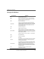
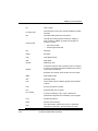
208BAcronyms & definitions
Acronyms & definitions
Acronym/Term
Definition
A/D
Analog to Digital Conversion
Base
Base is the back plane of the PLC on which the power
supply, communication and other modules gets installed
Examples: Main base, expansion base.
BCD
Binary Coded Decimal
Cold Restart
This is one of the CPU restart modes which affects the
variable parameters of the I/O image area when the CPU
is restarted. With the CPU restart mode set to cold restart,
all the parameters (like the internal register, timer and
counter) initialize to zero.
CPU
Central Processing Unit
D/A
Digital to Analog Conversion
Direct variable
Memory area which can be directly accessed with IEC
standard addressing notations with or without any variable
name.They are %I (input), %Q (output), and %M (internal
flags & registers) variables.
Address Examples: %IX0.0.2, %QW1.2.1, and %MD1234
Dnet
DeviceNet Network.
FEnet
Fast Ethernet Network.
FO
Fiber-Optic
Function
Is an operation unit that immediately outputs the operation
results for an input such as four arithmetical operations
and comparative operations.
Function Block
Is an operation unit, that memorizes the operation results
within the commands such as timer and counter or results
derived from several scans. Function blocks are the
fundamental element for logic programs. function blocks
like timer and counter have input and output connections
to indicate the flow.
HSL
iv
High Speed Link Service in MasterLogic-200
communication modules
Programmable Logic Controller 2MLI-CPUU CPU User's Guide
Honeywell Confidential & Proprietary
R 200
1/09
208BAcronyms & definitions
I/O
Input / Output
I/O image area
Internal memory area of CPU module installed to maintain
I/O states.
IEC
International Electrotechnical Commission
Interrupt Task
Interrupt driven task programs executed on meeting a
given condition in addition to regular scan programs. It
consists of 2 types –
•
Timer interrupt task
•
Internal flag Interrupt task
KB
Kilo Bytes
KStep
Kilo Steps
LSB
Least Significant Bit
MB
Mega Bytes
ML-200
MasterLogic-200
Module
A standard component with a specific function to configure
a system, such as the I/O board assembled to be inserted
into the base motherboard.
Examples: CPU module, power module, and I/O module.
R 200
1/09
MSB
Most Significant Bit
O/S
Operating System
P2P
Point to Point Service in MasterLogic-200 communication
modules
PAC
Process Automation Controller
PLC
Programmable Logic Controller
PLC System
A system consisting of a PLC, CPU, modules and
peripherals configured to be controlled by a user program.
Pnet
Profibus-DP Network.
RAM
Random Access Memory
RTC
As an abbreviation of Real Time Clock, it is collectively
referred as a universal IC, with the function of a clock.
Programmable Logic Controller 2MLI-CPUU CPU User's Guide
Honeywell Confidential & Proprietary
v
208BAcronyms & definitions
RTC
Real Time Clock
Snet
Serial Link Network.
SoftMaster
Programming tool for creating, editing, and debugging a
program.
STP
Shielded Twisted Pair
Symbolic variable
TP
Twisted Pair cables (typically CAT5 cables with RJ45
connectors for Ethernet communication)
UTP
Unshield Twisted Pair
Warm Restart
This is one of the CPU restart modes which affects the
variable parameters of the I/O image area when the CPU
is restarted. With the CPU restart mode is set to warm
restart, all the parameters (like the internal register, timer
and counter) retain the previous values.
Watchdog Timer
vi
Named Variables which are declared with a name, type
but address is automatically allocated in symbolic memory
area (%A) by the CPU. For instance, named variables
declared as ‘Valve1’, ‘Pump2’ or ‘Speed3’ with any IEC
standard data type.
A timer to monitor pre-determined execution time of a
program and to generate a warning, when it is not
complete within the time.
Programmable Logic Controller 2MLI-CPUU CPU User's Guide
Honeywell Confidential & Proprietary
R 200
1/09
209BContacts
Contacts
World Wide Web
For more information, visit the following Honeywell websites.
Honeywell Organization
WWW Address (URL)
Corporate
http://www.honeywell.com
Process Solutions
http://www.honeywell.com/ps
R 200
1/09
Programmable Logic Controller 2MLI-CPUU CPU User's Guide
Honeywell Confidential & Proprietary
vii
209BContacts
Telephone
Contact us by telephone at the numbers listed.
Location
Organization
Phone
United States
and Canada
Honeywell IAC Solution
Support Center
1-800-822-7673
Europe
Honeywell TAC-EMEA
+32-2-728-2704
Pacific
Honeywell Global TAC Pacific
1300-300-4822
(toll free within Australia)
+61-8-9362-9559
(outside Australia)
India
Honeywell Global TAC India
+91-20-2682-2458
Korea
Honeywell Global TAC Korea
+82-2-799-6317
People’s
Republic of
China
Honeywell Global TAC China
+86-10-8458-3280 ext. 361
Singapore
Honeywell Global TAC South East Asia
+65-6580-3500
Taiwan
Honeywell Global TAC Taiwan
+886-7-323-5900
Japan
Honeywell Global TAC Japan
Elsewhere
Call your nearest
Honeywell office.
viii
+81-3-5440-1303
Programmable Logic Controller 2MLI-CPUU CPU User's Guide
Honeywell Confidential & Proprietary
R 200
1/09
210BSymbol Definitions
Symbol Definitions
The following table lists the symbols used in this document, to denote certain conditions.
Symbol
Definition
ATTENTION: Identifies information that requires special
consideration.
TIP: Identifies advice or hints for the user, often in terms of
performing a task.
REFERENCE - EXTERNAL: Identifies an additional source of
information outside of the bookset.
REFERENCE - INTERNAL: Identifies an additional source of
information within the bookset.
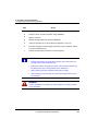
CAUTION
Indicates a situation which, if not avoided, may result in equipment
or work (data) on the system being corrupted or lost, or may result in
the inability to properly operate the process.
CAUTION: Indicates a potentially hazardous situation which, if not
avoided, may result in minor or moderate injury. It may also be used
to alert against unsafe practices.
CAUTION symbol on the equipment refers the user to the product
manual for additional information. The symbol appears next to
required information in the manual.
WARNING: Indicates a potentially hazardous situation, which, if not
avoided, could result in serious injury or death.
WARNING symbol on the equipment refers the user to the product
manual for additional information. The symbol appears next to
required information in the manual.
WARNING, Risk of electrical shock: Potential shock hazard where
HAZARDOUS LIVE voltages greater than 30 Vrms, 42.4 Vpeak, or
60 VDC may be accessible.
R 200
1/09
Programmable Logic Controller 2MLI-CPUU CPU User's Guide
Honeywell Confidential & Proprietary
ix
210BSymbol Definitions
Symbol
Definition
ESD HAZARD: Danger of an electro-static discharge to which
equipment may be sensitive. Observe precautions for handling
electrostatic sensitive devices.
Protective Earth (PE) terminal: Provided for connection of the
protective earth (green or green/yellow) supply system conductor.
Functional earth terminal: Used for non-safety purposes such as
noise immunity improvement.
NOTE: This connection shall be bonded to Protective Earth at the
source of supply, in accordance with the national local electrical
code requirements.
Earth Ground: Functional earth connection.
NOTE: This connection shall be bonded to Protective Earth at the
source of supply, in accordance with national and local electrical
code requirements.
Chassis Ground: Identifies a connection to the chassis or frame of
the equipment shall be bonded to Protective Earth at the source of
supply in accordance with national and local electrical code
requirements.
x
Programmable Logic Controller 2MLI-CPUU CPU User's Guide
Honeywell Confidential & Proprietary
R 200
1/09
Contents
1.
INTRODUCTION ..........................................................................17
1.1
Functional Overview ..................................................................................... 17
Overview of 2MLI-CPUU ......................................................................................................17
Features ...............................................................................................................................17
2.
SPECIFICATIONS........................................................................21
2.1
General specifications.................................................................................. 21
2.2
Battery ............................................................................................................ 24
Battery Specifications...........................................................................................................24
Cautions for usage ...............................................................................................................24
Battery Life ...........................................................................................................................24
2.3
Performance specifications ......................................................................... 25
2MLI-CPUU performance specifications ..............................................................................25
Part Names and Functions...................................................................................................28
2.4
Conformance to EMC Specifications .......................................................... 32
EMC Specifications ..............................................................................................................32
Control Panel .......................................................................................................................33
Cables ..................................................................................................................................35
2.5
Complying with the low voltage directive .................................................. 37
Specifications applicable to MasterLogic-200 Series ...........................................................37
Selecting a MasterLogic-200 Series PLC.............................................................................37
3.
HARDWARE - SPECIFICATIONS ...............................................39
3.1
Parts and functions....................................................................................... 39
Main Base ............................................................................................................................39
Expansion Base ...................................................................................................................40
Power Module ......................................................................................................................41
3.2
Main and Expansion Base............................................................................ 43
Main base specifications ......................................................................................................43
Expansion Base specifications.............................................................................................44
Extended Cable specifications .............................................................................................45
3.3
Power Module ................................................................................................ 46
Power Module specifications................................................................................................46
Example of Current Consumption/Power Calculations.........................................................50
R 200
1/09
Programmable Logic Controller 2MLI-CPUU CPU User's Guide
Honeywell Confidential & Proprietary
11
206BContents
210BSymbol Definitions
4.
INSTALLATION AND WIRING.................................................... 51
4.1
Installing the PLC ..........................................................................................51
Installation Environment ...................................................................................................... 51
Precautions for installing/handling the PLC modules .......................................................... 54
4.2
Inserting/Removing Modules........................................................................60
4.3
Wiring..............................................................................................................64
Power Wiring ....................................................................................................................... 64
I/O Device Wiring ................................................................................................................ 66
Grounding ........................................................................................................................... 67
Specifications of Wiring Cable............................................................................................. 68
5.
FUNCTIONS OF THE CPU MODULE ......................................... 69
5.1
Self-diagnostic Function...............................................................................69
Scan Watchdog Timer......................................................................................................... 69
I/O Module Check................................................................................................................ 70
Battery Voltage Check......................................................................................................... 70
Error Logs ........................................................................................................................... 70
Troubleshooting errors ........................................................................................................ 71
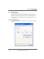
5.2
Clock Function...............................................................................................73
Read from SoftMaster/Setting ............................................................................................. 73
Clock Reading by Flag ........................................................................................................ 74
5.3
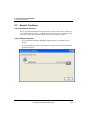
Remote Functions .........................................................................................76
Overview of Remote functions............................................................................................. 76
Types of Remote Operation ................................................................................................ 76
Flash Memory Operation Mode ........................................................................................... 78
5.4
Forced ON/OFF of I/O ....................................................................................81
Forced I/O Setting ............................................................................................................... 81
Forced On/Off Processing ................................................................................................... 82
Direct I/O Operation ............................................................................................................ 83
5.5
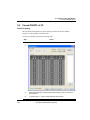
Viewing PLC Error/Event Log.......................................................................84
Overview of operation history .............................................................................................. 84
Error Log ............................................................................................................................. 84
Mode Change Log............................................................................................................... 84
Power shut down Log.......................................................................................................... 84
System Log ......................................................................................................................... 84
5.6
Diagnosing Faults of an External Device ....................................................87
Detection and classification of external device fault ............................................................ 87
Example .............................................................................................................................. 88
5.7
12
Fault Mask Function ......................................................................................89
Programmable Logic Controller 2MLI-CPUU CPU User's Guide
Honeywell Confidential & Proprietary
R 200
1/09
206BContents
210BSymbol Definitions
Fault Mask Operational overview .........................................................................................89
Setting Fault Mask ...............................................................................................................89
Releasing Fault Mask...........................................................................................................89
5.8
I/O Module Skip Function ............................................................................. 91
I/O Module skip operational overview ..................................................................................91
Setting and Processing I/O Data ..........................................................................................91
Releasing Skip Function.......................................................................................................91
5.9
Replacing a Module during Operation ........................................................ 93
Overview of replacing modules ............................................................................................93
Replacing Modules...............................................................................................................93
5.10
I/O Address................................................................................................. 95
Allocating I/O address ..........................................................................................................95
5.11
Program Modification................................................................................ 96
Program Modification during Operation................................................................................96
6.
CONFIGURATION .......................................................................97
6.1
System configuration ................................................................................... 97
2MLI-CPUU System Configuration.......................................................................................97
Components List ..................................................................................................................99
6.2
Basic system configuration ....................................................................... 105
Configuring the Basic System ............................................................................................105
Maximum Configuration of the Base System .....................................................................106
Connecting the Terminating Resistance ............................................................................108
6.3
Network system........................................................................................... 110
Inter-System Network.........................................................................................................110
Local Network ....................................................................................................................110
High Speed Link Service ....................................................................................................110
P2P service ........................................................................................................................111
Smart I/Os Modules (Remote I/O)......................................................................................111
I/O allocation method and I/O address assignment............................................................113
7.
PROGRAM STRUCTURE AND OPERATION METHOD...........115
7.1
Program Introduction ................................................................................. 115
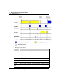
Program Operation Methods ..............................................................................................115
Operation of Instantaneous Interruption .............................................................................118
Scan Time ..........................................................................................................................119
7.2
Program Execution ..................................................................................... 122
Program Configuration .......................................................................................................122
Program Execution.............................................................................................................122
R 200
1/09
Programmable Logic Controller 2MLI-CPUU CPU User's Guide
Honeywell Confidential & Proprietary
13
206BContents
210BSymbol Definitions
Interrupt ............................................................................................................................. 124
7.3
Operation Mode ...........................................................................................134
Overview of the Operation MODE ..................................................................................... 134
RUN Mode ........................................................................................................................ 134
STOP Mode....................................................................................................................... 136
DEBUG Mode.................................................................................................................... 136
Changing Operation Mode ................................................................................................ 138
7.4
CPU Memory ................................................................................................140
Overview of CPU memory ................................................................................................. 140
Program Memory............................................................................................................... 140
Data Memory..................................................................................................................... 141
Data Retain Area Setting................................................................................................... 142
Data initialization by restart mode. .................................................................................... 143
Operation in the data retain area....................................................................................... 143
Data Initialization ............................................................................................................... 144
8.
MAINTENANCE......................................................................... 145
8.1
Repairs and Maintenance ...........................................................................145
I/O Module maintenance ................................................................................................... 145
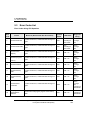
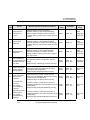
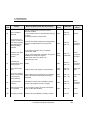
8.2
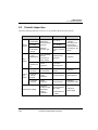
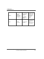
Routine Inspection ......................................................................................147
8.3
Periodic Inspection......................................................................................149
9.
TROUBLESHOOTING............................................................... 151
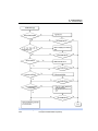
9.1
Basic Troubleshooting Procedure.............................................................151
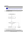
9.2
Troubleshooting ..........................................................................................152
Action when POWER LED is OFF..................................................................................... 152
Action when ERR. LED is ON ........................................................................................... 154
Action when RUN/STOP LED is Off .................................................................................. 156
Action when I/O module does not function properly .......................................................... 156
Action when Writing a Program to the CPU fails ............................................................... 159
9.3
Error Codes List...........................................................................................160
Error Codes during CPU Operation................................................................................... 160
10.
APPENDIX 1.............................................................................. 164
10.1
Flag List.....................................................................................................164
The Flags of Operation Mode and State Flags.................................................................. 164
System Error Flags............................................................................................................ 166
System Warning Flags ...................................................................................................... 169
14
Programmable Logic Controller 2MLI-CPUU CPU User's Guide
Honeywell Confidential & Proprietary
R 200
1/09
206BContents
210BSymbol Definitions
User’s Flags .......................................................................................................................169
Operation result flags .........................................................................................................171
The flags of the information of the system operation state .................................................172
10.2
Appendix Link Flags (L) List .................................................................. 174
Communication Flag List according to High speed link no. ................................................174
Communication Flag List according to P2P Service Setting...............................................176
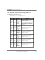
10.3
Appendix Communication Flags (P2P) List.......................................... 178
Link Register List according to P2P No. .............................................................................178
10.4
11.
Appendix 1.4 Reserved Words............................................................... 181
APPENDIX 2 DIMENSIONS (UNIT: MM) ...................................183
CPU Module.......................................................................................................................183
I/O Module..........................................................................................................................183
I/O Module connector type .................................................................................................184
Power Module ....................................................................................................................184
Main/Expansion Base ........................................................................................................185
Expansion Base .................................................................................................................186
R 200
1/09
Programmable Logic Controller 2MLI-CPUU CPU User's Guide
Honeywell Confidential & Proprietary
15
1. Introduction
1.1. Functional Overview
1. Introduction
1.1
Functional Overview
Overview of 2MLI-CPUU
The 2MLI-CPUU is a MasterLogic-200 PLC CPU using IEC 61131-3 standard
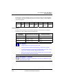
programming languages i.e. LD, SFC, ST. This document lists the specifications, and the
procedures for installing, handling, configuring and programming the CPU module.
Features
1.
Compact size:
The 2MLI-CPUU has all the functionality packed in a compact size, thus enabling
installation in small spaces. In addition, it reduces storage & freight costs.
2.
High Speed processing:
a)
MasterLogic’s high performance microprocessor technology provides a record
execution speed of :
−
Sequence command: 0.028µs / step
−
MOV instructions time: 0.084µs / step
b)
Real number operation: Improved operational speed of single/double
preciseness.
c)
+
−
×
÷
Single
real
0.602
0.602
1.106
1.134
Double
real
1.078
1.078
2.394
2.66
Improved Data transmission speed:
−
R 200
1/09
Item
16 point I/O module data process: 0.20 μs ~ 0.80 μs/module
Programmable Logic Controller 2MLI-CPUU CPU User's Guide
Honeywell Confidential & Proprietary
17
1. Introduction
1.1. Functional Overview
−
3.
−
Analog Channel data process: 0.20 μs ~ 0.80 μs/channel
−
1 KB communication module data process: 12.8 μs.
Parallel processing of I/O image refresh during program operations
Easy Use of Analog I/O Modules:
It guarantees precision in data collection, stability, and convenience by using:
•
Dedicated ‘%U’ address/memory area for data & status collection.
•
Setting Parameters without using memory maps for special modules like Analog
Input, Analog Output and so on.
4.
System Configuration:
The system is effectively configured keeping in mind the user’s needs:
•
Filter Value of the input modules can be adjusted.
•
Output can be kept on hold/clear during emergency.
•
Varistor is built-in with a durable relay output module.
•
The racks (main base and expansion base) can be extended up to 15m.
•
Provides system RUN status contact in power supply module.
•
Reduction of installation, commissioning, and maintenance costs by the
reinforced self-diagnostic function.
5.
Communication systems:
The communication module enables the user to communicate with the CPU using
different Protocols. It is also used by the CPU for communication with I/O’s and
Special Modules.
18
•
A network communication can be established without ladder programming.
•
The exclusive tool (SoftMaster-NM) monitors the operations and applies the
network settings
•
Open networks are supported with various international standards.
•
Provides a dedicated network to improve communication
•
Peer to Peer network compatible with other MasterLogic CPUs.
Programmable Logic Controller 2MLI-CPUU CPU User's Guide
Honeywell Confidential & Proprietary
R 200
1/09
1. Introduction
1.1. Functional Overview
6.
Online Editing:
SoftMaster enables the users to modify programs online, while CPU is in operation.
It enables:
•
Program reinforced by symbolic variables.
•
Ability to modify the program during operation and secure the stability
•
Installation and modification of network connections during operation.
•
Use of trend monitoring function
•
User event function.
•
Data trace function.
7.
Improved User experience:
Improved user experience with various functions supported:
•
R 200
1/09
Module Changing Wizard (It is used for changing the module online when PLC
is in RUN mode.)
•
System Diagnosis
•
Skip I/O
•
Fault Mask
•
Various Operation History
Programmable Logic Controller 2MLI-CPUU CPU User's Guide
Honeywell Confidential & Proprietary
19
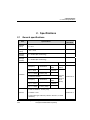
2. Specifications
2.1. General specifications
2. Specifications
2.1
General specifications
Item
Related
Standards
Specifications
Ambient
Temp.
0 ~ 55°C
Storage
Temp.
−25 ~ +70°C
Ambient
humidity
5 ~ 95%RH (Non-condensing)
Storage
humidity
5 ~ 95%RH (Non-condensing)
Occasional vibration
Vibration
-
Frequency
Acceleration
Pulse
width
10 ≤ f <57Hz
−
0.075mm
57 ≤ f ≤ 150Hz
9.8m/s2 (1G)
−
Continuous vibration
Frequency
Acceleration
Pulse
width
10 ≤ f < 57Hz
−
0.035mm
57 ≤ f ≤ 150Hz
2
4.9m/s (0.5G)
Sweep
Count
10 times
each
direction
(X, Y
and Z)
IEC61131-2
−
2
• Peak acceleration: 147m/s (15G)
Shocks
• Duration: 11ms
IEC61131-2
• Pulse wave type: Half-sine (3 times in each of X, Y and X
directions)
R 200
1/09
Programmable Logic Controller 2MLI-CPUU CPU User's Guide
Honeywell Confidential & Proprietary
21
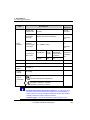
2. Specifications
2.1. General specifications
Item
Square wave
impulse noise
Electrostatic
discharge
Noise
immunity
Radiated
electromagneti
c field noise
Fast transient
/Burst noise
Internal
Test Spec
±1,500V
IEC61131-2
Voltage: 4kV (Contact discharge)
Classification
IEC610004-3
Power
supply
Digital/Analog
Input/Output,
Communicatio
n Interface
2kV
1kV
Atmosphere
Free from corrosive gases and excessive dust
Altitude
Less than 2,000m
Pollution
degree
Less than 2
Cooling
method
Air-cooling
IEC610004-2
IEC611312,
27 ~ 500MHz, 10V/m
Voltage
Agency
Certification
s
Related
Standards
Specifications
IEC61131-2
IEC610004-4
UL 508 Industrial Control Equipment
89/336/EEC, EMC Directive
EN 50081-2, Emissions, Industrial
EN 50082-2, Immunity, Industrial
ATTENTION
IEC (International Electrotechnical Commission) – An international civil
community that promotes international cooperation for standardization of
electric/ electro technology, publishes international standard and operates
suitability assessment system related to the above.
Pollution Degree – An index to indicate the pollution degree of used
22
Programmable Logic Controller 2MLI-CPUU CPU User's Guide
Honeywell Confidential & Proprietary
R 200
1/09
2. Specifications
2.1. General specifications
environment that determines the isolation performance of the device. For
example, pollution degree 2 means the state to occur the pollution of nonelectric conductivity generally, but the state to occur temporary electric
conduction according to the formation of dew.
Compliance to European Union Directives. This product has the CE mark and
is approved for installation within the European Union and EEA regions. It
has been designed and tested to meet the following directives:
EMC Directive. This apparatus is tested to meet Council Directive 89/ 336/
EEC Electromagnetic Compatibility (EMC) using a technical construction file
and the following standards, in whole or in part:
•
EN 50081- 2 EMC – Generic Emission Standard, Part 2 – Industrial
Environment
•
EN 50082- 2 EMC – Generic Immunity Standard, Part 2 – Industrial
Environment
•
The product described in this document is intended for use in an industrial
environment.
Low Voltage Directive. This product is also designed to meet Council
Directive 73/ 23/ EEC Low Voltage, by applying the safety requirements of
EN 61131– 2 Programmable Controllers, Part 2 – Equipment Requirements
and Tests.
R 200
1/09
Programmable Logic Controller 2MLI-CPUU CPU User's Guide
Honeywell Confidential & Proprietary
23
2. Specifications
2.2. Battery
2.2
Battery
Battery Specifications
Item
Specifications
Battery Type
Manganese Dioxide Lithium Battery
Nominal Voltage/Current
DC 3.0 V/1,800 mAh
Warranty period / Battery Life
5 years (at ambient temperature)
Program/data backup, RTC operation, in
Applications
case of power failure.
φ 17.0 X 33.5 mm
Dimensions
Cautions for usage
CAUTION
•
Heating up the battery or welding the electrode may reduce battery
life.
•
Attempting to measure the voltage of the battery with a tester; it
may cause a short circuit and fire.
•
Do not disassemble the battery.
Battery Life
•
The durability of the battery normally depends on power time-out, ambient
temperature and so on. However, the 2MLI-CPUU batteries are designed for use for
over 5 years in any environment.
If the voltage of a battery is lowered, CPU module shows a ‘Battery Voltage Drop
Warning’. It is possible to check this from the CPU module LED and flag or error
message in SoftMaster and Experion System Alarm.
•
The battery works for a limited amount of time, even after ‘Battery Voltage Drop
Warning’ occurs you can take an action after warning in the system of daily checking.
CAUTION
24
In general, the battery generates a warning, 5 years after purchase.
You may get an early warning, in case of excessive discharge because
of defects or leakage in the battery. If you get a warning, shortly after
replacing the battery, contact after-sales service.
Programmable Logic Controller 2MLI-CPUU CPU User's Guide
Honeywell Confidential & Proprietary
R 200
1/09
2. Specifications
2.3. Performance specifications
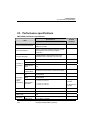
2.3 Performance specifications
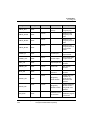
2MLI-CPUU performance specifications
Specifications
Item
2MLI-CPUU Non-redundant
Program Execution methods
Cyclic scan, Time-driven interrupts, Internal
Memory interrupts
I/O control method
Scan synchronous batch processing I/O (refresh
method), Direct I/O method by program
instruction
Program language
Ladder Diagram, Sequential Function Chart,
Structured Text, Instruction List (view only)
Number of
instruction
s
Processin
g speed
(Basic
instruction)
Operator
18
Basic functions
136 + real number operation function
Basic function
block
43
Dedicated
function block
Dedicated communication function blocks (P2P)
LD
0.028µs/Step
MOV
0.084µs/Step
Real number
operation
±: 0.392µs (S), 0.924µs (D)
÷: 0.924µs (S), 2.254µs (D)
x: 0.896µs (S), 2.240µs (D)
Program memory capacity
1MB (approx 128 KSteps)
Max # I/O bases
8 (main + 7 extension)
Max # slots
96
Max base
R 200
1/09
Using 64 ch
Related
Standards
S: Single real
number
D: Double real
number
6,144 (64ch * 96 slots)
Programmable Logic Controller 2MLI-CPUU CPU User's Guide
Honeywell Confidential & Proprietary
25
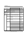
2. Specifications
2.3. Performance specifications
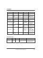
Specifications
Item
Related
Standards
2MLI-CPUU Non-redundant
DI/DO module
I/O
Using 32 ch
DI/DO module
Max I/O extension distance
Network / Remote I/O
(Max I/O memory)
Data
Memory
Capacity
Symbolic
Variable Area
(A)
3,072 (32ch * 96 slots)
15m (proprietary cable)
128,000
Counter
open standards
Using Smart
I/O modules
512 KB (Maximum, 256 KB retain settable)
No point limit
Timer
+
Time Range: 0.001 ~ 4,294,967.295 seconds
(1,193hours)
No point limit
Coefficient Range : -32,768 ~ +32,767
M
Occupying 20
bytes of
symbolic
variable area
per point
Occupying 8
bytes of
symbolic
variable area
per point
Fixed Area
Variable
R
Direct Variable
I
Input Image Area
Q
Output Image
Area
W
Flag Variables
26
%F
System Flag
%K
PID Flag
%L
High Speed Link
Flag
%N
P2P Flag
Programmable Logic Controller 2MLI-CPUU CPU User's Guide
Honeywell Confidential & Proprietary
R 200
1/09
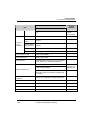
2. Specifications
2.3. Performance specifications
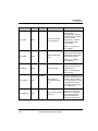
Specifications
Item
2MLI-CPUU Non-redundant
%U
Program
Type
Allocation
INIT task
1max
Timer Interrupt
tasks
32 max
Internal Device
Interrupt tasks
32 max
Scan program
Balance: 256 minus sum of above
Total
256 max
CPU operation mode
RUN, STOP, DEBUG
CPU restart mode
Cold or warm restart
Self-diagnosis
Watchdog timer, memory error, I/O error, battery
error, power error, communication error etc.
RS-232C(1CH)
USB (1CH) @ 12MBPS
Built-in Program port
Analog Refresh
Flag as
VAR_GLOBAL
Modbus slave
supported via
RS-232C port
Note: Additional program connections via
Ethernet & serial communication module (locate
or remote)
Data storage method at
power off
Retain area configuration via Basic parameters
Internal consumption current
960mA
Weight
0.12kg
Switchover Time
NA
Flash area
16MB
R 200
1/09
Related
Standards
Programmable Logic Controller 2MLI-CPUU CPU User's Guide
Honeywell Confidential & Proprietary
27
2. Specifications
2.3. Performance specifications
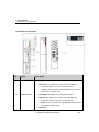
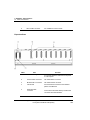
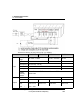
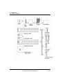
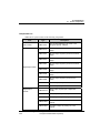
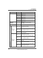
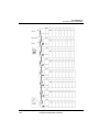
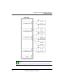
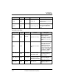
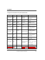
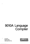
Part Names and Functions
No.
Names
Description
Specifies the operation state of CPU module.
•
Green ON: CPU operation is in ‘RUN’ mode state either by:
−
−
c-a
RUN/STOP LED
REMOTE ‘RUN’ operation through SoftMaster even when the
local switch is at ‘STOP’ mode
•
Green Blink: Warning or error during RUN operation
•
Red ON: CPU operation is in ‘STOP’ mode state either by:
−
−
•
28
RUN/STOP switch in CPU set to RUN mode (or)
RUN/STOP switch in CPU set to STOP mode (or)
REMOTE ‘STOP’ operation through SoftMaster even when the
local switch is at ‘RUN’ mode
Red Blink:
Programmable Logic Controller 2MLI-CPUU CPU User's Guide
Honeywell Confidential & Proprietary
R 200
1/09
2. Specifications
2.3. Performance specifications
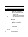
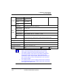
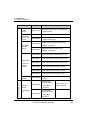
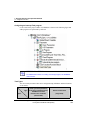
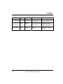
No.
Names
Description
−
c-b
REM LED
c-c
ERR LED
c-d
•
Yellow ON: ‘Remote enabled’ in case ’REMOTE’ switch is ‘ON’
•
OFF: ‘Remote disabled’ in case ‘REMOTE’ switch is ‘OFF’
•
Red ON: Error has occurred and CPU cannot operate normally.
•
OFF: Normal operation
•
Red ON:
o
‘User assigned flag’ is ‘ON’
PS LED
o
(Programmable
Status)
Operating in the error state by ‘operation proceeding in the
error’ setting
o
Module is detached or new module is installed in the state
where ‘M.XCHG‘ switch is ‘ON’
•
c-e
d-a
R 200
1/09
OFF: Normal operation
ON (Red): Battery voltage is low
BAT LED
OFF: Normal operation
•
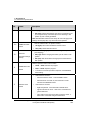
c-f
Warning or error during ‘STOP’ operation (if an error occurs,
stop the ongoing operation).
CHK LED
Boot/Nor switches
Red ON:
−
Setting is different from standard setting (its is possible to
add/delete [clear] by parameter)
−
‘Module change’ switch is set as ‘Module change’
−
Operating in ‘DEBUG mode’
−
‘Forced ON’ setting state
−
‘Fault mask’, ‘SKIP’ flag is set
−
Warning occurs during operation
−
Extended base power error
•
Red Blink: Arithmetic Operation Error during RUN.
•
OFF: Normal operation
Used to download new O/S or upgrade of CPU firmwares before
releasing the product.
Programmable Logic Controller 2MLI-CPUU CPU User's Guide
Honeywell Confidential & Proprietary
29
2. Specifications
2.3. Performance specifications
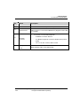
No.
Names
Description
•
ON (right): For normal CPU operation mode.
•
OFF (left): Used for download of new O/S. It is reserved for use
by Honeywell factory / authorized personnel. Switching to this
position by user is strictly prohibited.
Note: Both Boot/Nor switches must always be set to ON (right) side.
Setting it to OFF (left) side, may cause abnormal operation.
d-b
d-c
Used to enable the PLC to operate remotely
REMOTE enable
switch
•
ON (right): All functions enabled for remote control
•
OFF (left): Limited remote functions
Used while changing any module online during CPU operation
(hot-swapping).
M.XCHG
(Module exchange
switch)
•
ON (right): Before changing the module, put the switch in ON
position.
•
OFF (left): After the module is changed put the switch back to
OFF position.
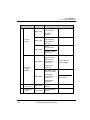
Sets the operation mode of CPU module.
e
RUN/STOP mode
Switch
•
STOP → RUN: executes the program
•
RUN → STOP: stops the program
•
•
f
Reset/ D.Clear
Switch
30
•
The above commands operates irrespective of the REMOTE
switch setting.
If this switch is moved to:
−
left and returned to center - executes RESET action
−
left and held for more than 3s, then returned to center:
executes Overall RESET action
If this switch is moved to
−
Right and pressed - it executes DATA CLEAR action.
−
right and returned to center - clear Latch 1 area data and
general data area
−
right, held for more than 3s and then returned to center - it
clears Latch 2 area data and general data area
Programmable Logic Controller 2MLI-CPUU CPU User's Guide
Honeywell Confidential & Proprietary
R 200
1/09
2. Specifications
2.3. Performance specifications
No.
Names
Description
Note: DATA CLEAR acts only in “STOP” operation mode.
g
USB connector
USB connector to connect with SoftMaster PC (Supports version USB
1.1 onwards)
•
h
A connector to connect with peripherals
−
RS−232C
connector
−
−
i
Battery built-in
Cover
R 200
1/09
SoftMaster connection with PLC
Any Modbus equipment connection: Modbus slave protocol
support
TX: no.7 Pin, RX: no.8 Pin, GND: no.5 Pin
Back-up battery built-in cover (bottom side)
Programmable Logic Controller 2MLI-CPUU CPU User's Guide
Honeywell Confidential & Proprietary
31
2. Specifications
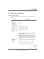
2.4. Conformance to EMC Specifications
2.4
Conformance to EMC Specifications
EMC Specifications
The EMC Directive specifies that products must ‘be so constructed that they do not cause
excessive electromagnetic interference (emissions) and are not unduly affected by
electromagnetic interference (immunity)’. The applicable products are requested to meet
these requirements.
This section summarizes the precautions for the MasterLogic-200 PLC to ensure
conformance to the EMC Directive. Details of these precautions are based on the
requirements and the applicable standards. However, Honeywell does not guarantee that
the overall system manufactured according to these details conforms to the directives
listed in the following table.
The method of conformance to the EMC directive and the judgment on whether or not
the system conforms to the EMC Directive must be finally determined by the
manufacturer of the system.
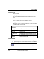
The standards applicable to the EMC Directive are as follows:
Specification
Test items
EN55011
Radiated
noise
EN50081-2
EN55011
conducted
Standard value
30~230
/m 1
QP : 50
230~1000
/m
Measure the noise that
a product emits to the
power line.
QP : 57
150~500
QP : 79
Mean
: 66
500~230
QP : 73
Mean
: 60
EN61000-4Electrostatic
immunity
Immunity test allowing
static electricity to the
case of a device.
15
EN61000-4-4
Immunity test allowing a
fast noise to power
cable and signal cable.
Power line : 2
Fast transient
burst noise
32
Measure the wave
emitted from a product.
2
noise
EN61131-2
Test details
Air discharge
8 Contact
discharge
Digital I/O : 1
Analog I/O, signal
lines : 1
Programmable Logic Controller 2MLI-CPUU CPU User's Guide
Honeywell Confidential & Proprietary
R 200
1/09
2. Specifications
2.4. Conformance to EMC Specifications
Specification
Test items
EN61000-4-3
Radiated field
AM modulation
EN61000-4-12
Damped
oscillatory wave
immunity
Test details
Standard value
Immunity test injecting
electric field to a
product.
10Vm, 26~1000
Immunity test allowing
attenuation vibration
wave to power cable.
Power line : 1
80% AM
modulation@ 1
Digital I/O(24V and
higher) : 1
QP: Quasi Peak, Mean: average value.
A PLC is an open type device (device installed on another base) and must be installed on
a control panel. The system tests are performed after installing the PLC on a control
panel.
Control Panel
The PLC is a device susceptible to noise. To protect it from noise, it must be installed on
a control panel. This also prevents chances of electric shock and reduces PLC-generated
noise. Installing the PLC on a metallic panel reduces PLC-generated EMI (Electromagnetic interference).
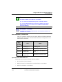
Control Panel specifications
The Masterlogic-200 PLC must be installed on a metallic panel to restrict EMI emitted
from the product. The specifications of the metallic panel are as follows:
R 200
1/09
1.
Use SPCC (Cold Rolled Mild Steel) for the control panel.
2.
The thickness of the steel plate must be atleast 1.6mm.
3.
Use isolating transformers to protect power supply from external surge voltage.
4.
The control panel must have a structure that prevents radio waves from entering.
For example, make the door as a box-structure so that the panel body and the door
overlap each other. This structure reduces the surge voltage generated by PLC.
Programmable Logic Controller 2MLI-CPUU CPU User's Guide
Honeywell Confidential & Proprietary
33
2. Specifications
2.4. Conformance to EMC Specifications
Power Cable and Grounding specifications
Grounding and power supply wires for the PLC system must be connected as follows:
1.
34
Ground the control panel with a thick wire so that a low impedance connection to
ground can be ensured even at high frequencies.
Programmable Logic Controller 2MLI-CPUU CPU User's Guide
Honeywell Confidential & Proprietary
R 200
1/09
2. Specifications
2.4. Conformance to EMC Specifications
2.
The function of LG (Line Ground) and FG (Frame Ground) terminals is to pass the
noise generated in the PLC system to the ground, to ensure an impedance as low as
possible.
3.
To prevent the grounding wire from acting as an antenna and generating noise, keep
the wire as short and thick as possible.
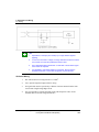
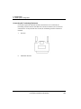
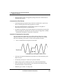
Cables
Extension cable connection
The extension cables contain high frequency noise. Therefore, attach a ferrite core to the
extension cable as shown in the following figure, to meet the CE conformance standards.
R 200
1/09
Programmable Logic Controller 2MLI-CPUU CPU User's Guide
Honeywell Confidential & Proprietary
35
2. Specifications
2.4. Conformance to EMC Specifications
Model
Manufacturer
CU1330D
E-TECH ELECTRONICS
ZCAT3035-1330
TDK
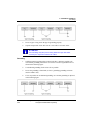
Fixing a cable in the panel
When connecting an extension to the metal panel, maintain a space of at least 1cm from
the panel. The metal board of the control panel has a shielding effect that blocks noise. If
a metal panel is in in contact with a cable it could serve as an antenna and thereby be a
source of noise.
36
Programmable Logic Controller 2MLI-CPUU CPU User's Guide
Honeywell Confidential & Proprietary
R 200
1/09
2. Specifications
2.5. Complying with the low voltage directive
CAUTION
2.5
Keep all high-speed signal transmission cables at a safe distance from
the metal board.
Complying with the low voltage directive
The low-voltage directive requires each device that operates with power supply ranging
from 50V to 1000VAC and 75V to 1500VDC to satisfy the safety requirements. This
section describes the precautions to ensure the installation and wiring of the
MasterLogic-200 series conform to the low-voltage directive.
WARNING
The contents of this section are based on the requirements and the
applicable standards control. However, Honeywell does not guarantee that
the overall product manufactured according to these details conforms to the
low voltage regulation.
Specifications applicable to MasterLogic-200 Series
•
The MasterLogic-200 series follows EN6100-1 (safety of devices used in
measurement rooms, control rooms or laboratories).
•
The MasterLogic-200 series modules that operate at the rated voltage of AC 50V/DC
75V or above are also developed to conform to the low voltage standards.
Selecting a MasterLogic-200 Series PLC
1.
Power Module: The voltages inside the power supply modules are extremely
dangerous. Peak voltage can be higher than 42.4V for the AC 110/220V rated I/O
voltages. Therefore, the CE mark-compliant models are internally enhanced in
isolation between the primary and secondary.
2.
Digital I/O Module: The voltages inside the Digital I/O modules are extremely
dangerous. Peak voltages can be higher than 42.4V for the AC 110/220V rated I/O
voltages. Therefore, the CE mark-compliant models are internally enhanced in
isolation between the primary and secondary.
The I/O modules of DC 24V or of less rating are out of the low-voltage directive
application range.
3.
R 200
1/09
CPU Module, Base Unit: These modules use DC 5V and 3.3V circuits, so they are
out of the low-voltage directive application range.
Programmable Logic Controller 2MLI-CPUU CPU User's Guide
Honeywell Confidential & Proprietary
37
2. Specifications
2.5. Complying with the low voltage directive
4.
38
Special Module, Communication Module: The special module and
communication modules use DC 24V or less rated voltage, therefore they are out of
the low-voltage directive application range.
Programmable Logic Controller 2MLI-CPUU CPU User's Guide
Honeywell Confidential & Proprietary
R 200
1/09
3. Hardware - Specifications
3.1. Parts and functions
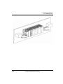
3. Hardware - Specifications
3.1
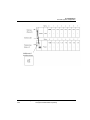
Parts and functions
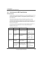
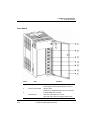
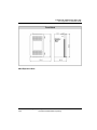
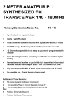
Main Base
Index
Part
Function
1
Base attached guide hole
It is used to attach the main base to the panel
in control panel
2
Power module connector
For installation of Power Supply module
Module built-in connector
For installation of I/O, special & other
communiucation modules
3
R 200
1/09
4
FG terminal
Ground terminal connected to the shielded
pattern of PCB board
5
Extended cable connector
Connects the extended cable by send/receive
connector with extended base.
Programmable Logic Controller 2MLI-CPUU CPU User's Guide
Honeywell Confidential & Proprietary
39
3. Hardware - Specifications
3.1. Parts and functions
6
CPU module connector
For installation of CPU module
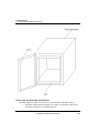
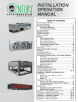
Expansion Base
Index
40
Part
Function
1
Base attached guide hole
It is used to attach the main base to the panel
in control panel
2
Power module connector
I/O module built-in connector
3
Module built-in connector
I/O module built-in connector
4
FG terminal
Ground terminal connected to the shielded
pattern of PCB board
5
Extended cable
connector
Connects the extended cable by send/receive
connector with extended base.
Programmable Logic Controller 2MLI-CPUU CPU User's Guide
Honeywell Confidential & Proprietary
R 200
1/09
3. Hardware - Specifications
3.1. Parts and functions
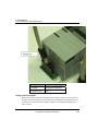
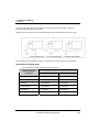
Power Module
Index
1
2
Part
Function
Power LED
DC5V power indication LED
DC24V, 24G terminal
Power supply to the module required for DC24V in
output module.
2MLP-ACF2, 2MLP-ACF3 does not print out DC24V.
3
Indicates RUN state of system.
RUN terminal
OFF when CPU STOP error occurs.
OFF when CPU mode is changed to STOP mode.
R 200
1/09
Programmable Logic Controller 2MLI-CPUU CPU User's Guide
Honeywell Confidential & Proprietary
41
3. Hardware - Specifications
3.1. Parts and functions
4
FG terminal
5
LG terminal
Ground terminal for electric shock prevention
Ground terminal of power filter
Power input terminal
6
Power input terminal
2MLP-ACF1, 2MLP-ACF2, 2MLP-AC23,
2MLP-DC42
7
42
Terminal cover
Terminal block protection cover
Programmable Logic Controller 2MLI-CPUU CPU User's Guide
Honeywell Confidential & Proprietary
R 200
1/09
3. Hardware - Specifications
3.2. Main and Expansion Base
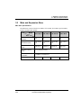
3.2
Main and Expansion Base
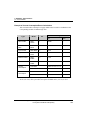
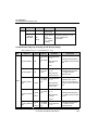
Main base specifications
The Main base consists of the Power module, CPU module, I/O module, Special module,
and the Communication module.
Model
Item
R 200
1/09
2MLB-M12A
2MLB-M08A
2MLB-M06A
2MLB-M04A
No. of I/O modules
installed
12
8
6
4
Dimensions (mm)
426 X 98 X
19
318 X 98 X
19
264 X 98 X
19
210 X 98 X
19
Hole distance to attach
panel
406 X 75
298 X 75
244 X 75
190 X 75
Hole size to attach
panel
φ 4.5 (using M4 screw)
Screw size for FG
connection
(+)PHM 3 X 6 washer(φ 5)
Weight (kg)
0.54
0.34
0.28
0.42
Programmable Logic Controller 2MLI-CPUU CPU User's Guide
Honeywell Confidential & Proprietary
43
3. Hardware - Specifications
3.2. Main and Expansion Base
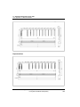
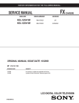
Expansion Base specifications
The expansion base consists of the Power module, I/O module, Special module, and the
Communication module.
Model
Item
44
2MLB-E12A
2MLB-E08A
2MLB-E06A
2MLB-E04A
No. of I/O modules
12
8
6
4
Dimensions (mm)
481 X 98 X
19
318 X 98 X
19
264 X 98 X
19
210 X 98 X
19
Distance of hole for
panel attachment
461 X 75
298 X 75
244 X 75
190 X 75
Specification of hole for
panel attachment
φ 4.5 (M4 screw used)
Specification of screw
for FG connection
(+)PHM 3 X 6 washer (φ 5)
Weight (kg)
0.59
0.39
0.33
0.47
Programmable Logic Controller 2MLI-CPUU CPU User's Guide
Honeywell Confidential & Proprietary
R 200
1/09
3. Hardware - Specifications
3.2. Main and Expansion Base
Extended Cable specifications
Model
2MLCE041
2MLCE061
2MLCE121
2MLCE301
2MLCE501
2MLCE102
2MLCE152
Length (m)
0.4
0.6
1.2
3
5
10
15
Weight (kg)
0.15
0.16
0.22
0.39
0.62
1.2
1.8
Item
ATTENTION
Do not exceed the length of 15m, in case of a combination of extended
cables.
R 200
1/09
Programmable Logic Controller 2MLI-CPUU CPU User's Guide
Honeywell Confidential & Proprietary
45
3. Hardware - Specifications
3.3. Power Module
3.3
Power Module
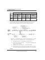
Power Module specifications
The selection of a power module is determined by the current and voltage needed by the
system. The voltage requirement of a system is calculated as a sum of the current
consumption by the digital I/O modules, special modules, CPU module, power module
and the communication module (installed on the same base as the power module.)
The system does not operate normally if the rated output capacity of the power module
exceeds the predefined limit.
The following table lists the current consumption per module (DC 5V):
Module
CPU module
DC12/24V input
module
AC110V input
module
46
Model
Current
consump
tion (mA)
Module
Model
Current
consump
tion (mA)
2MLFAV8A
420
2MLFAC8A
420
2MLICPUU
960
2MLID21A
20
2MLFAD4S
610
2MLID22A
30
2MLFDV4A
190 (250)
2MLID22B
30
2MLFDC4A
190 (400)
2MLID24A
50
2MLFDC4S
200 (200)
2MLID24B
50
2MLFDV8A
147 (180)
2MLID28A
60
2MLFDC8A
243 (300)
2MLID28B
60
2MLFHO2A
270
2MLIA12A
30
2MLFHD2A
330
A/D
conversion
module
D/A
conversion
module
High Speed
Counter
module
Programmable Logic Controller 2MLI-CPUU CPU User's Guide
Honeywell Confidential & Proprietary
R 200
1/09
3. Hardware - Specifications
3.3. Power Module
Module
AC220V input
module
Relay output
module
Transistor output
module
Triac output
module
FEnet module
(optical/electrical)
FDEnet
module(Master)
R 200
1/09
Model
Current
consump
tion (mA)
Model
Current
consump
tion (mA)
2MLIA21A
20
2MLFPO3A
400
2MLQRY1A
250
2MLFPO2A
360
2MLQRY2A
500
2MLFPO1A
340
2MLQRY2B
500
2MLFPD3A
860
2MLQTR2A
70
2MLFPD2A
790
2MLQTR2B
70
2MLFPD1A
510
2MLQTR4A
130
Thermocouple
input module
2MLFTC4S
610
2MLQTR4B
130
2MLQTR8A
230
2MLFRD4A
490
2MLQTR8B
Resistance
temperature
detector input
module
230
2MLQSS2A
300
Profibus-DP
module
2MLLPMEA
560
2MLLEFMF
650
2MLLC22A
330
2MLLEFMT
420
2MLLC42A
300
2MLLEDMF
650
2MLLCH2A
340
Module
Positioning
module
Snet module
Programmable Logic Controller 2MLI-CPUU CPU User's Guide
Honeywell Confidential & Proprietary
47
3. Hardware - Specifications
3.3. Power Module
The following table lists the specifications of the Power Module:
Items
Input
Output1
48
2MLP-ACF1
2MLP-ACF2
2MLP-AC23
2MLP-DC42
Rated input
voltage
AC 100V – AC 240V
AC 200V – AC 240V
DC 24V
Input voltage
range
AC 85V ~ AC 264V
AC 170V ~ AC 264V
-
Input frequency
50 / 60 Hz (47 ~ 63 Hz)
-
Inrush current
20 APeak or less
80APeak or less
Efficiency
65% or more
60% or more
Input fuse
Built-in (user no change), UL standard (Slow Blow Type)
Allowable
momentary
shutdown
Within 20ms
Output voltage
DC 5V (±2%)
Output current
3.0A
6.0A
8.5A
6.0A
Over current
protect
3.2A or more
6.6A or more
9.0A or more
6.6A or more
Over voltage
protect
5.5V ~ 6.5V
DC5V (±2%)
Programmable Logic Controller 2MLI-CPUU CPU User's Guide
Honeywell Confidential & Proprietary
R 200
1/09
3. Hardware - Specifications
3.3. Power Module
Output2
Relay
Output
Output voltage
DC 24V (±10%)
Output current
0.6A
Over current
protect
0.7A or more
Over voltage
protect
None
Application
RUN contact (Refer to the section 8.3)
Rated switching
voltage/current
DC 24V, 0.5A
Minimum
switching load
DC 5V,1
Response time
OFF→ON/ ON→OFF: 10
-
-
or less/12
Mechanical: More than 20,000,000 times
Life
Electrical: More than 100,000 times at rated switching voltage/current
RUN signal output
Relay output, Rating: DC24V, 0.5A
Voltage indicator
Output voltage normal, LED ON
Cable specification
0.75 ~ 2mm2
Compressed terminal
RAV 1.25 - 3.5, RAV 2 - 3.5
Weight
0.4kg
R 200
1/09
or less
0.6kg
0.5kg
1.
Allowable Momentary Power Failure Time: The time that input voltage
keeps normal output voltage (normal operation) in the state that
AC110/220V voltage is lower than the rated value (AC85 / 170V).
2.
Over current protection: If the current is more than the standard and
flows in DC5V, DC24V circuit, the over current protection device
shutsdown the circuit to stop the system. Remove the causes such as
lack of current capacity or short circuits that leads to over current and
then restart the system.
3.
Over voltage protection: The over voltage protection device shuts down
the circuit to stop the system, if the voltage is greater than the standard
and is applied to the DC5V circuit
Programmable Logic Controller 2MLI-CPUU CPU User's Guide
Honeywell Confidential & Proprietary
49
3. Hardware - Specifications
3.3. Power Module
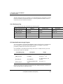
Example of Current Consumption/Power Calculations
This section describes which power supply module must be used in coordination to the
corresponding modules for MasterLogic-200.
Type
Model
No.
Voltage
5V
24V
CPU module
2MLICPUU
1
0.96A
-
12 Slot basic
base
2MLBM12A
-
-
-
Input module
2MLI-D24A
4
0.2A
-
Output module
2MLQRY2A
4
2.0A
-
FDEnet module
2MLLEDMF
2
1.3A
-
Profibus-DP
2MLLPMEA
2
1.12A
-
Current
consumption
Calculation
0.96+0.2+2+1.3+1.12
-
Result
5.58A
-
Power
consumption
Calculation
5.58×5V
-
Result
27.9W
-
As the value of 5V current consumption is 5.58A, use 2MLP-ACF2 (5V: 6A) or 2MLPAC23 (5V: 8.5A). The system does not operate if 2MLP-ACF1 (5V: 3A) is used.
50
Programmable Logic Controller 2MLI-CPUU CPU User's Guide
Honeywell Confidential & Proprietary
R 200
1/09
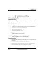
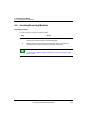
4. Installation and Wiring
4.1. Installing the PLC
4. Installation and Wiring
4.1
Installing the PLC
Installation Environment
The PLC system is designed to withstand extreme climatic conditions. However, care
must be taken for the following items to ensure reliability and stability.
Environmental Conditions
Dos
•
Install the PLC in a control panel which is waterproof and can withstand vibration.
•
Install the PLC away from areas with high vibration.
•
Ensure an ambient temperature of 0 ~ 55 ○C.
•
Esure incremental Humidity: 5 ~ 95 %.
Don’ts
•
Do not expose the PLC to direct sun-light.
•
Avoid exposing the PLC to sudden changes in the temperature.
•
Do not expose the PLC to corrosive or inflammable gases.
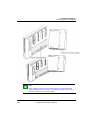
Installation Conditions
R 200
1/09
•
While drilling holes, fixing screws or wiring, do not let wire or any other metallic part
enter the PLC.
•
Do not install the PLC on a panel that has a high-voltage device
•
Maintain a distance of atleast 50mm from the wiring duct or surrounding modules.
•
Ensure the grounding at a place where surrounding noise is minimal.
Programmable Logic Controller 2MLI-CPUU CPU User's Guide
Honeywell Confidential & Proprietary
51
4. Installation and Wiring
4.1. Installing the PLC
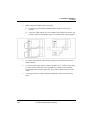
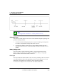
Heat Protection Design of Control Panel
•
In case the PLC is installed in an airtight control panel, the heat protection design
must be esnured considering the radiation of other equipment, and heat from the
PLC. When air circulation is provided using a vent or a general fan, the flow of dust
particles or gas can hamper the functioning of the PLC system.
•
Installing a filter or use of an airtight heat exchanger is recommended.
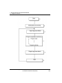
The following figure illustrates the method used for calculating the current consumption
of PLC system necessary for heat protection design.
Power consumption of each part
1.
Current Consumption of Power Module
The current conversion efficiency of the power module is around 70 %. Radiation
consumes 30%, and current consumption is 3/7 of the output power. The calculation is as
follows.
Wpw = 3/7 {(I5V X 5) + (I24V X 24)} (W)
52
I (5V)
Current consumption of DC 5V circuit of each
module (internal current consumption)
I (24V)
Average current consumption of DC 24V of
output module (current consumption of
simultaneous ON point)
Programmable Logic Controller 2MLI-CPUU CPU User's Guide
Honeywell Confidential & Proprietary
R 200
1/09
4. Installation and Wiring
4.1. Installing the PLC
If DC24V is externally supplied or a power module without DC24V is used, it is not
applicable.
2.
Sum of DC 5V circuit current consumption: The DC 5V output circuit current of
the power supply module is the sum of current consumption of each module.
W 5V = I5V X 5 (W)
3.
DC 24V Average current consumption (current consumption of simultaneous ON
point): DC 24V output circuit average current of power module is the sum of
current consumption of each module.
W 24V = I24V X 24 (W)
4.
Average current consumption by output voltage drop of output module (current
consumption of simultaneous ON point)
i. Wout = Iout X V drop X output point X simultaneous ON rate (W)
ii. Iout: Output current (current in actual use) (A)
iii. V drop: Voltage drop of each output module (V)
5.
Input average current consumption of input module (current consumption of
simultaneous ON point)
i. Win = lin X E X input point X simultaneous ON rate (W)
ii. Iin: Input current (actual value in case of AC) (A)
iii. E: Input voltage (voltage in actual use) (V)
6.
Current consumption of Special module power assembly
WS = I5V X 5 + I24V X 24 + I100V X 100 (W)
The sum of the current consumption calculated for each block is the total current
consumption of PLC system.
W = WPW + W5V + W24V + Wout + Win + Ws (W)
Calculate the amount of radiation according to this total current consumption (W) and
review the temperature rising in the control panel. Use the following formula for the
calculation of the temperature rise in control panel.
T = W / UA [°C]
Where,
W = power consumption of the entire PLC system (the calculated value)
A = surface area of control panel [m2]
U : if equalizing the temperature of the control panel by using a fan and others - - - 6
R 200
1/09
Programmable Logic Controller 2MLI-CPUU CPU User's Guide
Honeywell Confidential & Proprietary
53
4. Installation and Wiring
4.1. Installing the PLC
If the air inside the panel is not ventilated - - - - - - - - - - 4
Precautions for installing/handling the PLC modules
Take the following precautions while handling or installing modules.
•
Do not drop the PLC module or apply excessive force on it.
•
Avoid touching the PCB inside the module with bare hands as this can lead to failure
of the PLC Modules.
•
Ensure that foreign materials such as wiring fragments do not enter the upper part of
modules casing. Even if such materials accidentally enter the module casing, remove
them immediately.
Precautions for installing/handling I/O module
Note the following points about handling or installing I/O module.
1.
Recheck I/O module specifications
Check the input voltage for input modules. For output modules, check if the voltage
applied exceeds the maximum Open/Close capacity. Over voltage may lead to failure,
damage or sparking.
2.
Cable selection
Select the appropriate cable after considering its capacity to withstand temperature and
intensity of current flowing through it. The minimum specification of cable must be
AWG22 (0.3mm2).
3.
Environment
When wiring an I/O module, ensure that it is not too close to a heat emitting equipment.
In addition, avoid the wires from coming in direct contact with oil, as it may cause a
short circuit, breakage or can cause abnormal errors during operation.
4.
Polarity
The polarity of the module terminals and that of the field signal must be the same.
5.
•
54
Wiring
The I/O must be wired using high-voltage cables or power cables. Lower voltage
wires can cause inductive disturbance that may result in abnormalities or failure of
PLC operation.
Programmable Logic Controller 2MLI-CPUU CPU User's Guide
Honeywell Confidential & Proprietary
R 200
1/09
4. Installation and Wiring
4.1. Installing the PLC
•
Ensure that the cables do not pass in front of the I/O operation indicator (LED) as it
may obstruct the indicator.
•
When inductive load is connected to output module, connect a surge absorber or
diode in parallel to the load.
•
Terminal Block Wiring
WARNING
Do not apply apply excessive pressure on the I/O module or separate the
PCB board from the case.
Honeywell does not bear any responsibility if the user removes the PCB
board from the case.
Precautions for installing the base
The following precautions must be taken while installing a PLC on the control panel.
R 200
1/09
1.
Ensure sufficient ventilation for the modules, especially the upper part of the
modules. This also helps in changing the modules, if required.
2.
If the PLC is installed near a Contactor/Breaker, it is recommended to use a
Contactor/Breaker (Large Size) in a different panel.
Programmable Logic Controller 2MLI-CPUU CPU User's Guide
Honeywell Confidential & Proprietary
55
4. Installation and Wiring
4.1. Installing the PLC
3.
4.
If necessary install wiring duct for routing the cables. Make note of the following
points when installing a wiring duct:
−
When installing the wiring duct on the upper part of the PLC, ensure that its
distance is more than 50mm to enable adequate ventilation. Maintain sufficient
distance from the upper part of the PLC, so that the module can be removed
easily.
−
When installing the wiring duct on the lower part of the PLC, take into account
the connection of the optical cable or coaxial cable, and the minimum cable radius
without breaking the cable.
Install PLC in the direction as shown in the following figure. This helps in
protecting the PLC from radiation.
Do not install the PLC in the direction, as in the following figure:
56
Programmable Logic Controller 2MLI-CPUU CPU User's Guide
Honeywell Confidential & Proprietary
R 200
1/09
4. Installation and Wiring
4.1. Installing the PLC
To avoid any effect of radiating noise or heat, install the PLC, and other devices (relay and
electronic contact) with a spacing secured, as indicated in the following figure:
R 200
1/09
Programmable Logic Controller 2MLI-CPUU CPU User's Guide
Honeywell Confidential & Proprietary
57
4. Installation and Wiring
4.1. Installing the PLC
58
Programmable Logic Controller 2MLI-CPUU CPU User's Guide
Honeywell Confidential & Proprietary
R 200
1/09
4. Installation and Wiring
4.1. Installing the PLC
R 200
1/09
Programmable Logic Controller 2MLI-CPUU CPU User's Guide
Honeywell Confidential & Proprietary
59
4. Installation and Wiring
4.2. Inserting/Removing Modules
4.2
Inserting/Removing Modules
Inserting a module
Use the following procedure to attach a module:
Step
Action
1
Insert the projection on the lower part of the module into the Module fixing
hole of the PLC base as shown in the following figure.
2
Slide the upper part of module to fix into the base. Use the screws in the
upper part of the module to hold the module firmly to the base.
TIP
To check if the module is properly installed in the base, slowly pull the upper
part of module.
60
Programmable Logic Controller 2MLI-CPUU CPU User's Guide
Honeywell Confidential & Proprietary
R 200
1/09
4. Installation and Wiring
4.2. Inserting/Removing Modules
TIP
When installing modules, insert the fixed projection of the module into the
module-fixing hole and then press it. The module may break if the module is
forced onto the base in an incorrect position.
R 200
1/09
Programmable Logic Controller 2MLI-CPUU CPU User's Guide
Honeywell Confidential & Proprietary
61
4. Installation and Wiring
4.2. Inserting/Removing Modules
Detaching modules
To detach modules, perform the following steps:
Step
62
Action
1
From the base, loosen the fixed screws on the upper part of the module.
2
Hold the module using both hands and thoroughly press the fixed hook of the
module.
3
Pull the upper part of the module from the axis of the lower part, by pressing
the hook.
4
By lifting the module upward, remove the fixed projection of the module from
the fixing hole.
Programmable Logic Controller 2MLI-CPUU CPU User's Guide
Honeywell Confidential & Proprietary
R 200
1/09
4. Installation and Wiring
4.2. Inserting/Removing Modules
CAUTION
R 200
1/09
While detaching the module, press the hook and remove the module
from the base, only then remove the fixed projection of the module
from the fixed hole of module. In this case, if module is detached
forcefully, a hook or the fixed projection of the module can break.
Programmable Logic Controller 2MLI-CPUU CPU User's Guide
Honeywell Confidential & Proprietary
63
4. Installation and Wiring
4.3. Wiring
4.3
Wiring
Power Wiring
64
1.
Connect a voltage regulated transformer if the power variance is higher than the
specified range.
2.
In case of excessive interference (noise) use an Isolation transformer.
3.
The following figure illustrates the distributions of 220V AC for PLC Power
Supply, I/O Modules and other Mains Circuit Equipment.
Programmable Logic Controller 2MLI-CPUU CPU User's Guide
Honeywell Confidential & Proprietary
R 200
1/09
4. Installation and Wiring
4.3. Wiring
4.
R 200
1/09
While using Power Module of DC 24V output:
a)
Do not connect the module in parallel with the output of several power
modules.
b)
If DC 24V output capacity of a power module is not sufficient for the PLC I/O
modules, supply the external DC 24V power as shown in the following figure.
5.
AC110V/AC220V/DC24V cables must be properly twisted and connected in the
shortest distance.
6.
AC110V/AC220V cable must be as thick as possible (2mm2), to reduce voltage drop.
AC110V/ DC24V cables must not be installed close to main circuit cable (high
voltage/high current) and I/O signal cable. They must be 100mm away from such
cables.
7.
Use a surge absorber as a protection against lightning as shown in the following
figure.
Programmable Logic Controller 2MLI-CPUU CPU User's Guide
Honeywell Confidential & Proprietary
65
4. Installation and Wiring
4.3. Wiring
TIP
1.
Separate PLC earth (E2) from earth (E1) of surge absorber against
lightning.
2.
In case of an increase in voltage, the surge absorber ensures that it does
not increase more than the predefined maximum limit.
3.
Use a shielded Isolation transformer or noise filter in areas where higher
noise levels are expected.
4.
It is advisable to use twisted cable for input power. Ensure that the
shielded transformer or noise filter wiring does not pass the duct.
I/O Device Wiring
66
1.
The cable used for I/O wiring must be 0.3~2.0mm2.
2.
Use a separate input and output cable for wiring.
3.
I/O signal cable must be separated by a distance of atleast 100mm from the main
circuit cable of high voltage/high current.
4.
If it is not possible to separate the main circuit cable and power cable, use the
shielded cable in all cases and ground the PLC.
Programmable Logic Controller 2MLI-CPUU CPU User's Guide
Honeywell Confidential & Proprietary
R 200
1/09
4. Installation and Wiring
4.3. Wiring
5.
In case of pipe wiring, check the pipe for grounding properly.
6.
Separate output cable of DC 24V from AC 110V cable or AC 220V cable.
ATTENTION
Current leakage may take place for wiring distances longer than 200m,
caused by the capacitance between the cables.
Grounding
R 200
1/09
1.
Sufficient measures against noise are taken in the PLC, making it possible to be
used without grounding. When there is lot of noise its better to ground the PLC as
shown in the following figure.
2.
Use dedicated grounding for the wires as far as possible.
3.
In case the grounding is functional, use class 3 grounding (grounding resistance
must be 100Ω or less).
4.
If it is not possible to use dedicated grounding, use common grounding as depicted
in the following figure.
Programmable Logic Controller 2MLI-CPUU CPU User's Guide
Honeywell Confidential & Proprietary
67
4. Installation and Wiring
4.3. Wiring
Use more than 2mm2 cables for grounding. Place the earth point near the PLC as much as
possible to limit the length of earth cable.
Separate LG (Line Ground) of power module and FG (Frame Ground) of base board for earth.
If any malfunction on grounding is detected, separate the FG of the base from the grounding.
Specifications of Wiring Cable
The specifications of cable used for wiring are as follows:
Types of external
connection
68
Cable specification (mm2)
Lower limit
Upper limit
Digital input
0.18 (AWG24)
1.5 (AWG16)
Digital output
0.18 (AWG24)
2.0 (AWG14)
Analog I/O
0.18 (AWG24)
1.5 (AWG16)
Communication
0.18 (AWG24)
1.5 (AWG16)
Main power
1.5 (AWG16)
2.5 (AWG12)
Protective grounding
1.5 (AWG16)
2.5 (AWG12)
Programmable Logic Controller 2MLI-CPUU CPU User's Guide
Honeywell Confidential & Proprietary
R 200
1/09
5. Functions of the CPU Module
5.1. Self-diagnostic Function
5. Functions of the CPU Module
5.1
Self-diagnostic Function
The CPU module can perform a self-diagnosis to locate any errors in the PLC system. It
can also prevent abnormal operations resulting from the error.
Scan Watchdog Timer
WDT (Watchdog Timer) is a function run by the CPU module that detects program
congestion through hardware and software errors of PLC.
R 200
1/09
1.
WDT is the timer, used to detect operation delay by user program error. The
detection time of WDT is set in basic parameter using SoftMaster.
2.
If WDT detects the excess of setting time during the scan while watching the
operation, it stops the operation of PLC immediately, and switches off all the
outputs.
3.
If the excess of Scan Watchdog Timer is expected during program processing of the
specific part while performing the user program (FOR ~ NEXT instruction, CALL
instruction), clear the timer by using ‘WDT’ instruction.
4.
The ‘WDT’ instruction initializes the elapsed time of Scan Watchdog Timer and
starts the time measurement from 0 again.
5.
Use the following method to clear the error state of watchdog:
−
Power reset, operation of manual reset switch
−
Mode conversion to STOP mode.
Programmable Logic Controller 2MLI-CPUU CPU User's Guide
Honeywell Confidential & Proprietary
69
5. Functions of the CPU Module
5.1. Self-diagnostic Function
TIP
The range of WDT is between 10 ~ 1000ms (resolution of 1ms).
I/O Module Check
This function is used to check the error state of an I/O module during the beginning of an
operation or during operation.
1.
In case the module installed physically is not as per the module type configured in
the software (I/O parameter settings) then it shows an error.
2.
In case the I/O module is removed or error occurs during operation, the error is
detected and indicated by the warning lamp (ERR) and the CPU module ceases to
operate.
Battery Voltage Check
The CPU module is capable of detecting a battery voltage drop below the memory
backup voltage. On detecting a low battery level and the low battery warning lamp
(BAT), located on front of CPU module is turned on.
Error Logs
The CPU module has a function that records error history and analyzes the cause of these
errors. This enables the user to take appropriate corrective action when the error occurs
subsequently. This function saves each error code in a special flag F0006.
All results of self-diagnosis are recorded in the ‘%F’ address/memory area.
70
Programmable Logic Controller 2MLI-CPUU CPU User's Guide
Honeywell Confidential & Proprietary
R 200
1/09
5. Functions of the CPU Module
5.1. Self-diagnostic Function
REFERENCE – INTERNAL
For additional information on self-diagnostic and troubleshooting errors see
section on ‘Error Codes during CPU Operation’.
Troubleshooting errors
Classification of Errors
An error is classified as a ‘Fatal Error’ and ‘Non Fatal Error’. A fatal error stops
operation for system safety and ‘Non Fatal Error’ warns the user about the error and
continues to operate.
The PLC system normally encounters the following types of errors:
1.
PLC hardware error
2.
Error in system configuration
3.
Operation error during user program processing
4.
Error detection by external device failure
Mode of Operation on detecting a fault
When error occurs, the PLC records the error comments, flags it, and stops all operations
or continues to operate in Error Mode.
•
PLC hardware error
In case of a fatal hardware error, the CPU module and power module of the PLC is
disabled and the system stops. However if the error is non-fatal such as a battery
error, then the system continues operating in Error Mode.
•
Error in system configuration
This error occurs when hardware configuration of the PLC is not in line with the
software configuration. This causes the system to stop.
•
Operation Error during User Program Processing
This error occurs while user program is being executed and also in case of numeric
operation error. The error is recorded, flagged and the system continues to operate.
However if the operation time exceeds the scan watchdog time or the built-in I/O
module is unable to function normally, the system stops.
R 200
1/09
Programmable Logic Controller 2MLI-CPUU CPU User's Guide
Honeywell Confidential & Proprietary
71
5. Functions of the CPU Module
5.1. Self-diagnostic Function
TIP
The operation process is determined by selecting ‘Basic Parameters → Error
Operation Setup → Continue running when an arithmetic error occurs’.
The default is set to ‘Continue running when an arithmetic error occurs’.
•
Error detection by external device error
This is to detect an error in an external control device by using the PLC program. In
case of a fatal error the system stops, but in case of non fatal error the system
provides an indication about the error state and continues to operate.
TIP
The error codes are saved in special flag %F1026 when a fatal error is
detected.
The error code is saved in %F1027 when a non-fatal error is detected.
REFERENCE - INTERNAL
For additional information on the Flags, see Appendix 1.
72
Programmable Logic Controller 2MLI-CPUU CPU User's Guide
Honeywell Confidential & Proprietary
R 200
1/09
5. Functions of the CPU Module
5.2. Clock Function
5.2
Clock Function
The CPU module has an in-built real-time clock device (RTC). In a power OFF or
instantaneous interruption, the RTC continues to function using the battery back-up. The
clock data of the RTC is used to provide the time control for operations or fault logs.
The current time of the RTC is updated to the clock-related %F address/memory area at
every scan period.
Read from SoftMaster/Setting
Click Online>PLC Information on the SoftMaster menu bar. The following dialog box
is displayed.
R 200
1/09
Programmable Logic Controller 2MLI-CPUU CPU User's Guide
Honeywell Confidential & Proprietary
73
5. Functions of the CPU Module
5.2. Clock Function
The RTC displays the time set in the PLC. You can adjust the time on the RTC by setting
the time to be directly transmitted to the PLC or select ‘Synchronize with PC clock’ to
transmit the PC time connected to the PLC.
Clock Reading by Flag
It can be monitored by flags as detailed in the following table.
Flags to read the clock
Address
Sample Value
Description
_MON_YEAR_DT
%FW1034
h0599
May, xx99
_TIME_DAY_DT
%FW1035
h1512
3 P.M., 12th
_SEC_MIN_DT
%FW1036
h4142
42 minutes 41 seconds
_HUND_WK_DT
%FW1037
h2001
20xx, Monday
The time data of _TIME_DAY_DT is displayed on 24 hrs basis.
RTC Data Modification through Program
You can set the RTC value using the SoftMaster program. This function is used when the
time is manually set using the external digital switch or by designing a system that
periodically calibrates the clock time on the network.
Set ‘DATEWR’ to ON and insert the setting value in the %F address/memory area and
enter the time in RTC at scan END.
Clock Writing Flag
Description
Range
_MON_YEAR_DT
Month/Year
Jan ~ Dec ,1984 ~ 2163
_TIME_DAY_DT
Hour/Date
0~23 hrs , 1st ~31st
_SEC_MIN_DT
Second/Minute
0 ~ 59 seconds, 0 ~ 59
minutes
_HUND_WK_DT
Hundred years/day of the
week
00 ~ 99, 0 ~ 6
Enter the time data in the format prescribed in the table. Monitor the RTC read device to
check if the RTC data is modified correctly.
74
Programmable Logic Controller 2MLI-CPUU CPU User's Guide
Honeywell Confidential & Proprietary
R 200
1/09
5. Functions of the CPU Module
5.2. Clock Function
The Weekday expression method is used to represent the weekday in a Ladder Program.
For example, 3 represents a Wednesday wherever we need to specify a date as indicated
in the following table.
Number
Day
0
1
2
3
4
5
6
Sund
ay
Monday
Tuesda
y
Wedne
sday
Thursd
ay
Friday
Saturda
y
Time tolerance
The RTC tolerance depends on the ambient temperature. Time tolerance according to
temperature per day is indicated in the following table:
Operating
Temperature
Maximum error (sec/date)
Ordinary (sec/date)
0 °C
- 4.67 ~ 1.38
-1.46
25 °C
- 1.64 ~ 2.42
0.43
55 °C
- 5.79 ~ 0.78
-2.29
ATTENTION
•
Initially, the RTC may not have any clock data.
•
Set the clock data correctly before beginning to use the CPU module.
•
In case the data is out of range of the clock data written in the RTC, it may
not function normally. Example: 14Month 32Day 25Hour
•
RTC may stop or give an error because of battery error. If new clock data
is written in the RTC, the error is cleared.
REFERENCE – INTERNAL
For additional information on modifying the clock data, see ‘MasterLogic-200
Instructions User Guide’.
R 200
1/09
Programmable Logic Controller 2MLI-CPUU CPU User's Guide
Honeywell Confidential & Proprietary
75
5. Functions of the CPU Module
5.3. Remote Functions
5.3
Remote Functions
Overview of Remote functions
The key switch installed on the local CPU is used to operate a remote CPU, connected to
it. To operate the CPU remotely, set ‘REM’ switch (no. 2 dip switch of 4 pin dip switch)
of the CPU module ‘ON’ and move ‘RUN/STOP’ switch to ‘STOP’ position.
Types of Remote Operation
76
•
By connecting the SoftMaster through the USB or RS-232 port available in CPU
module.
•
By using SoftMaster to connect to another PLC on the same network as illustrated in
the following figures.
Programmable Logic Controller 2MLI-CPUU CPU User's Guide
Honeywell Confidential & Proprietary
R 200
1/09
5. Functions of the CPU Module
5.3. Remote Functions
Remote RUN/STOP
•
Remote RUN/STOP function performs RUN/STOP when the DIP switch of the CPU
module is in REMOTE position and RUN/STOP switch is in STOP position.
•
When the CPU module is installed in an inaccessible location and is difficult to
operate, it is convenient to control it using Remote RUN/STOP.
Remote DEBUG
•
Remote DEBUG is a function that performs DEBUG operation when DIP switch of
the CPU module is in REMOTE position and RUN/STOP switch is in STOP position.
•
It is convenient to check the execution state of a program or the contents of each data
from Debugging function using REMOTE DEBUG Mode.
Remote Reset
R 200
1/09
•
Remote Reset function is used to reset a CPU module by running a remote operation
when an error occurs and it is not possible to operate a CPU module.
•
This supports ‘Reset’ and “Overall Reset’ like an operation by switch.
Programmable Logic Controller 2MLI-CPUU CPU User's Guide
Honeywell Confidential & Proprietary
77
5. Functions of the CPU Module
5.3. Remote Functions
REFERENCE - INTERNAL
For the further information about remote functions, refer to the ‘Online’
section in the SoftMaster User’s Manual.
Flash Memory Operation Mode
In the Flash memory operation mode, the system operates from the program in flash
memory, in case the program in the RAM is corrupted. When “Flash Memory Operation
Mode” is enabled, the program is saved into flash memory. The flash memory operation
starts when the operation mode is changed to RUN mode from any other mode or while
CPU restart.
•
78
Flash Memory Operation Mode Setting. Check the operation mode setting by using
Online > Set Flash Memory > Enable flash memory run mode and click OK.
When “Enable flash memory run mode” selection is accepted, a dialog box appears
stating “Saving flash memory program” and copies the program from user program
area to flash memory.
Programmable Logic Controller 2MLI-CPUU CPU User's Guide
Honeywell Confidential & Proprietary
R 200
1/09
5. Functions of the CPU Module
5.3. Remote Functions
ATTENTION
The default option is ‘Flash Memory Operation Mode not selected’.
Flash Memory Operation Mode can be changed, irrespective of RUN/STOP
mode.
Flash Memory Operation Mode can be set from the online menu of
SoftMaster.
If the flash memory operation setting is modified to flash memory operation
mode during RUN and the program is successfully written in the flash
memory, the changed program shall be applied only when it restarts. Note
that if the PLC restarts before a program is saved into flash memory, the
previous program that was saved earlier operates, instead of the changed
program.
If flash memory operation mode is changed from ‘disable’ to ‘enable’, the
flash memory operation mode is applied until the flash memory writing is
complete. In case the PLC restarts before completing program writing, “Flash
memory operation mode” is released.
Flash memory operation method
Depending on the Flash Memory operation mode setting, the PLC operates as indicated
in the following table when the PLC is restarted or its operating mode is ON:
Flash memory operation mode
setting
R 200
1/09
Description
Programmable Logic Controller 2MLI-CPUU CPU User's Guide
Honeywell Confidential & Proprietary
79
5. Functions of the CPU Module
5.3. Remote Functions
Flash memory operation mode
setting
80
Description
On
If program memory data is corrupted because flash
memory and program memory are different or
battery voltage is low, it downloads the program
saved in the flash memory to the program memory.
Off
CPU detects that the flash memory does not have
any program and operates by the program saved in
the RAM.
Programmable Logic Controller 2MLI-CPUU CPU User's Guide
Honeywell Confidential & Proprietary
R 200
1/09
5. Functions of the CPU Module
5.4. Forced ON/OFF of I/O
5.4
Forced ON/OFF of I/O
Forced I/O Setting
The forced I/O setting function is used to forcibly turn ON or OFF I/O channels,
irrespective of the program execution results.
To force I/O ON/OFF, perform the following steps:
Step
1
Action
Click Online>Force I/O…on the SoftMaster menu bar.
2
R 200
1/09
3
Select appropriate flag and select appropriate data check box of P device to
set Forced I/O.
4
To set the value “1”, select corresponding bit data and flag.
Programmable Logic Controller 2MLI-CPUU CPU User's Guide
Honeywell Confidential & Proprietary
81
5. Functions of the CPU Module
5.4. Forced ON/OFF of I/O
Step
Action
5
To set the value “0”, select only the flag.
6
The setting is applied when forced input or output is enabled.
ATTENTION
•
Forced I/O setting is applicable only on DI/DO modules. It is not
applicable to special modules.
•
Forced I/O setting is available only in local I/O modules. It cannot be set in
remote I/O module (smart I/O module). When forced I/O is set, “CHK
LED” is ON.
•
The forced I/O setting is maintained, even after a new program is
downloaded.
WARNING
Forcing can energise the I/O and may cause serious malfunction in the
process or threat to human life.
REFERENCE - INTERNAL
For additional information on Forced I/O setting, see SoftMaster User’s
Manual.
Forced On/Off Processing
Forced input
The input forces the data of the contact point (Digital Input) selected and set as forced
ON/OFF. At the time of input refresh the forced data is updated to the input image area.
Therefore, the user program operates with actual input data while the forced setting area
operates with forced setting data.
Forced output
The Output replaces data of contact point (Digital Output) selected and set as forced
ON/OFF from the data of output image area. This is achieved during output refresh, on
completion of the user program operation execution with the forced setting data. It makes
changes in the output module. In case of output, the data of output image area does not
change by forced ON/OFF setting.
82
Programmable Logic Controller 2MLI-CPUU CPU User's Guide
Honeywell Confidential & Proprietary
R 200
1/09
5. Functions of the CPU Module
5.4. Forced ON/OFF of I/O
Cautions for using forced I/O
•
For Forcing the point the Force Flag needs to be set .
•
It is possible to set the forced input even if the actual I/O module not installed.
•
The data set in the CPU is retained till it is cleared.
•
Forced I/O data is not cleared even CPU is in Stop mode.
•
Click ‘Delete all’ to clear all settings and set forced value again.
Direct I/O Operation
The ‘DIREC_IN, DIREC_OUT’ function is used to change the I/O values. This enables
the user to read the state of input and output contact points directly during program
execution.
ATTENTION
When DIREC_IN,DIREC_OUT’ function is used, the value is applied
immediately, and it precedes Forced I/O.
REFERENCE - INTERNAL
For additional information about the DIREC_IN,DIREC_OUT’ function, see
the SoftMaster Instruction manual.
R 200
1/09
Programmable Logic Controller 2MLI-CPUU CPU User's Guide
Honeywell Confidential & Proprietary
83
5. Functions of the CPU Module
5.5. Viewing PLC Error/Event Log
5.5
Viewing PLC Error/Event Log
Overview of operation history
There are four types of logs:
•
Error log
•
Mode change log
•
Shut down log
•
System log
The PLC saves the time, frequency, and operation of each event in memory. This can be
monitored from SoftMaster. The operation log is continuously saved in the PLC unless it
is deleted using SoftMaster.
Error Log
The PLC saves the errors that occur during operation into an error log. It saves the
following details of errors:
•
Error code, date, time, and error details.
•
Error history of the errors that occur during operation
It saves a maximum of 2,048 messages. The saving of error history is automatically
diabled in case memory backup fails due to low battery
Mode Change Log
In the event of a change in operation mode, the PLC saves this information with a timestamp:
•
Saves the date, time, and mode change information
•
Saves up to 1,024 mode change events
Power shut down Log
The PLC saves power ON/OFF data, with its time stamp. It saves On/Off information,
date and time. It saves a maximum of 1,024 power ON/OFF events.
System Log
The PLC saves operation history of the system during operation:
•
84
Saves the date, time, and operation changes
Programmable Logic Controller 2MLI-CPUU CPU User's Guide
Honeywell Confidential & Proprietary
R 200
1/09
5. Functions of the CPU Module
5.5. Viewing PLC Error/Event Log
•
Saves the SoftMaster operation data, key switch change information
•
Saves instantaneous interruption data and network operation
•
Saves a maximum of 2,048 operation history events
ATTENTION
R 200
1/09
•
The saved information is not deleted until you select the delete menu from
SoftMaster.
•
In case there are more than 100 events, the ‘Read All’ button is enabled.
Click Read All to check the history.
Programmable Logic Controller 2MLI-CPUU CPU User's Guide
Honeywell Confidential & Proprietary
85
5. Functions of the CPU Module
5.5. Viewing PLC Error/Event Log
86
Programmable Logic Controller 2MLI-CPUU CPU User's Guide
Honeywell Confidential & Proprietary
R 200
1/09
5. Functions of the CPU Module
5.6. Diagnosing Faults of an External Device
5.6
Diagnosing Faults of an External Device
All the Errors in an external device (devices wired to I/O modules) are detected by CPU
and is available in a Flag as a real time value. This flag enables the indication of an
external device error without preparing a complicated program.
Detection and classification of external device fault
The errors in an external device can be detected by the user program. They are classified
as the following types:
•
‘Non-Fatal Error’ (warning). When this type of error occurs, the PLC continues to
operate in RUN mode. It only gives an indication about the device state according to
the contents of detected warning.
•
‘Fatal Error’, this type of error occurs, the PLC stops operation and goes to STOP
mode. Fatal error, ‘_ANC_ERR’ flag is used and for non fatal error, ‘_ANC_WAR ’
flag is used.
Handling a fatal error in an external device
R 200
1/09
1.
In a user program, if a fatal error of external device is detected, the error type can be
set by a user program. For this, the user needs to write the value except ‘0’ in the
system flag, ‘_ANC_ERR’. While checking Scan Program completion time, if any
error occurs, it is indicated in the system representative error flag ‘_ANNUM_ER’
of ‘_CNF_ER’. PLC then shuts off all output modules and gives an error.
2.
If case of an error, a user can find the cause by using SoftMaster or by monitoring
the ‘_ANC_ERR’ flag.
3.
The ERR LED, P.S LED, and CHK LEDs are turned ON by the fatal fault error flag
of an external device. The LEDs can be turned OFF by resetting the PLC. Turn the
PLC OFF and then ON to turn off the LEDs.
Programmable Logic Controller 2MLI-CPUU CPU User's Guide
Honeywell Confidential & Proprietary
87
5. Functions of the CPU Module
5.6. Diagnosing Faults of an External Device
Handling a non-fatal error in an external device.
1.
When a Non-fatal Error (warning) in an external device occurs, select the flag of the
corresponding position as ON ‘_ANC_WB’ according to user identification from
system flag. At the end of the scan program, if a warning is detected when checking
from ‘_ANC_WB [0]’, it is indicated by the system representative error flag,
‘_ANNUN_WR’ of ‘_CNF_WAR’. The number of non-fatal error of external
device is recorded in the order of occurrence from ‘_ANC_WAR [0]’ to
‘_ANC_WAR [7]’.
2.
If any error occurs, a user can find the cause of that error using SoftMaster or the
cause of warning by monitoring ‘_ANC_WAR’ and ‘_ANC_WB’ flags directly.
3.
If the non-fatal error of external device is released, from ‘_ANC_WB[n]’ after
performing the user program, it is automatically removed from the
‘_ANC_WAR[n]’ flag and if all are released, ‘_ANNUN_WR’ system flag
‘_CNF_WAR’ is re-set.
Example
88
Programmable Logic Controller 2MLI-CPUU CPU User's Guide
Honeywell Confidential & Proprietary
R 200
1/09
5. Functions of the CPU Module
5.7. Fault Mask Function
5.7
Fault Mask Function
Fault Mask Operational overview
Fault mask enables uninterrupted program execution even in the case of an error in the
module.
•
If the error occurs in the module where the Fault Mask is set, the corresponding
module stops operation. However the rest of the system continues to operate.
•
If the module error occurs when the PLC is in RUN mode, the CPU module sets the
error flag and the front “PS LED” turns “ON”. You can see the error state through
SoftMaster.
Setting Fault Mask
The Fault mask can be set from the online menu of SoftMaster. Fault mask can be also
set by a program. It is achieved by setting fault mask flag with a program.
REFERENCE - INTERNAL
For additional information on Fault Mast setting, see SoftMaster User’s
Manual.
For additional information on setting fault mask through a program, see
Appendix 1 Flags list.
Releasing Fault Mask
The Fault mask can be released in the following ways:
•
Setting release from online menu of SoftMaster.
•
Release by program.
•
Automatic release in case memory backup is lost because of battery voltage falling.
The fault mask is not released in the following cases:
R 200
1/09
1.
Power Off→On
2.
Operation mode change
3.
Program download
4.
Reset key (released only when it is pressed for 3 seconds and longer.)
5.
Data clear
Programmable Logic Controller 2MLI-CPUU CPU User's Guide
Honeywell Confidential & Proprietary
89
5. Functions of the CPU Module
5.7. Fault Mask Function
ATTENTION
Check the state of the error flag before releasing the Fault Mask flag. The
system goes to STOP mode if the Fault Mask is released without clearing the
Error Flag.
90
Programmable Logic Controller 2MLI-CPUU CPU User's Guide
Honeywell Confidential & Proprietary
R 200
1/09
5. Functions of the CPU Module
5.8. I/O Module Skip Function
5.8
I/O Module Skip Function
I/O Module skip operational overview
The I/O module skip function is used to exclude a designated module from operation
while the PLC is in RUN Mode. The I/O data updation and error diagnosis ceases for the
designated module. It is used when to operate it temporarily, excluding the fault.
Setting and Processing I/O Data
The SoftMaster is used to configure the skip setting on the I/O module.
REFERENCE – INTERNAL
For additional information about skip setting, see SoftMaster User’s Manual.
•
Input (I) image area suspends input refresh, and maintains the value set before the
skip setting. At this time, it is possible to operate the image by forced ON/OFF.
•
The actual output of the output module is set to OFF, when setting the skip function.
But output image changes depending on a user program’s operation, irrespective of
the skip setting. After the skip setting, the output value of the output module cannot
be controlled by forced ON/OFF.
•
The skip function executed similarly as described above, even while using I/O
function.
Releasing Skip Function
The I/O module skip function is released by the following methods:
•
Using the online menu of SoftMaster
•
Releasing by overall reset
•
Automatically release, in case of memory backup failure because of low battery level
Note that the fault mask is not released in the following cases:
R 200
1/09
•
Power Off→On.
•
Operation mode change.
•
Program download.
•
Reset key (Released only when it is pressed for 3 seconds and longer.)
Programmable Logic Controller 2MLI-CPUU CPU User's Guide
Honeywell Confidential & Proprietary
91
5. Functions of the CPU Module
5.8. I/O Module Skip Function
•
Data clear.
ATTENTION
If a fault is found in a module when releasing the skip function, the system
may stop. Before releasing the skip function, ensure the release os the skip
with fault mask set and check the operation of a module.
92
Programmable Logic Controller 2MLI-CPUU CPU User's Guide
Honeywell Confidential & Proprietary
R 200
1/09
5. Functions of the CPU Module
5.9. Replacing a Module during Operation
5.9
Replacing a Module during Operation
Overview of replacing modules
The MasterLogic-200 system enables the user to change modules while the PLC is in
RUN mode. However, special care must be taken while changing the modules as it can
lead to abnormalities in the system.
CAUTION
During PLC operation:
•
Do not replace the base and power module.
•
Some communication modules (2MLL-PMEA, 2MLL-DMEA) can be
connected as long as network is set (using Sycon software).
•
When replacing a module, align the bottom of the base and the
holding part of a module before inserting it. Incorrect installation
may cause the system to shutdown.
Replacing Modules
Following are the methods to change modules:
Using the “Module Replacement Wizard” of SoftMaster.
REFERENCE – INTERNAL
For additional information, see SoftMaster User’s Manual.
Using the CPU module switch.
Step
Action
1
Set “Module change switch (M.XCHG)” in front of CPU module to right (ON).
2
Remove the module. (PS LED is ON).
3
Setup the new module. (In case of normal module setup, PS LED is OFF)
4
Check if module operates normally.
5
Set “Module change switch (M.XCHG)” to left (OFF).
Using fault mask and skip function of SoftMaster
Step
R 200
1/09
Action
Programmable Logic Controller 2MLI-CPUU CPU User's Guide
Honeywell Confidential & Proprietary
93
5. Functions of the CPU Module
5.9. Replacing a Module during Operation
Step
Action
1
Set fault mask to a slot, to replace a module using SoftMaster.
2
Set skip to a slot, to replace a module using SoftMaster.
3
Replace a module.
4
Release the skip setting of a part from SoftMaster.
5
Check the operation for any errors (Refer to Appendix 1, Flag List).
6
Even while replacing a module again, because of a fault of replaced module,
it must be repeated from (1).
7
Release the fault mask and restore to normal operation.
ATTENTION
•
During the procedure, the I/O module operating on the same base may
provide incorrect data instantaneously.
•
Because of a fault in the replaced module, a fault of another module may
be detected. It is safe to set fault mask for the entire base.
•
While replacing a module, isolate the load power for safety.
•
While replacing an input module, check the input image status by using
forced On/Off.
WARNING
Incorrect installation of a module may cause malfunction of another module
on the same base.
94
Programmable Logic Controller 2MLI-CPUU CPU User's Guide
Honeywell Confidential & Proprietary
R 200
1/09
5. Functions of the CPU Module
5.10. I/O Address
5.10 I/O Address
Allocating I/O address
I/O address allocation refers to assigning the address to the I/O terminal of each module.
This enables reading data from an input module and transmitting the data to an output
module.
The I/O number allocation is related with base number, slot position and module type.
The number is allocated by the fixed method in the 2MLI-CPUU.
The base has its base number as ‘0’ and the extension base has a switch to set the base
number. The following table provides the guidance for base number setting:
Base Number
Setting
0
0001
1
0011
2
0100
3
0111
REFERENCE – INTERNAL
To see examples of I/O number allocation, see section on Basic System
Configuration.
R 200
1/09
Programmable Logic Controller 2MLI-CPUU CPU User's Guide
Honeywell Confidential & Proprietary
95
5. Functions of the CPU Module
5.11. Program Modification
5.11 Program Modification
Program Modification during Operation
During PLC operation, a program and some parameters can be modified without
interruption to the control.
REFERENCE – INTERNAL
For additional information on Program modification during operation, refer
SoftMaster User’s Manual.
The items modifiable during operations are as follows:
•
Program.
•
Communication parameters.
ATTENTION
The basic parameters and I/O parameters cannot be modified during
operation. To modify these parameters, it is necessary to stop operation.
96
Programmable Logic Controller 2MLI-CPUU CPU User's Guide
Honeywell Confidential & Proprietary
R 200
1/09
6. Configuration
6.1. System configuration
6. Configuration
6.1
System configuration
2MLI-CPUU System Configuration
The system configuration of the 2MLI-CPUU is as follows:
R 200
1/09
Programmable Logic Controller 2MLI-CPUU CPU User's Guide
Honeywell Confidential & Proprietary
97
6. Configuration
6.1. System configuration
98
Programmable Logic Controller 2MLI-CPUU CPU User's Guide
Honeywell Confidential & Proprietary
R 200
1/09
6. Configuration
6.1. System configuration
Components List
2MLI-CPUU system consists of the following components.
Item
CPU module
Type
2MLI-CPUU
CPU module (Maximum I/O points: 6,144,
Program capacity: 1MByte).
2MLI-D21A
DC 24V input, 8 points (current source/sink
input).
2MLI-D22A
DC 24V input, 16 points (current source/sink
input).
2MLI-D24A
DC 24V input, 32 points (current source/sink
input).
2MLI-D28A
DC 24V input, 64 points (current source/sink
input).
2MLI-D22B
DC 24V input, 16 points (current source
input).
2MLI-D24B
DC 24V input, 32 points (current source
input).
2MLI-D28B
DC 24V input, 64 points (current source
input).
2MLI-A12A
AC 110V input, 16 points.
2MLI-A21A
AC 220V input, 8 points.
2MLQ-RY1A
Relay output, 8 points (2A, independent
COM).
2MLQ-RY2A
Relay output, 16 points (2A).
2MLQ-RY2B
Relay output, 16 points (2A), built-in Varistor.
2MLQ-TR2A
Transistor output, 16 points (0.5A, sink
output).
2MLQ-TR4A
Transistor output, 32 points (0.1A, sink
output).
Digital input module
Digital output
module
R 200
1/09
Description
Programmable Logic Controller 2MLI-CPUU CPU User's Guide
Honeywell Confidential & Proprietary
99
6. Configuration
6.1. System configuration
Item
Main base
Extension base
Power module
Extension cable
(Total length must
100
Type
Description
2MLQ-TR8A
Transistor output, 64 points (0.1A, sink
output).
2MLQ-TR2B
Transistor output 16 points (0.5A, source
output).
2MLQ-TR4B
Transistor output 32 points (0.1A, source
output).
2MLQ-TR8B
Transistor output 64 points (0.1A, source
output).
2MLQ-SS2A
Triac output, 16 points (0.6A).
2MLB-M04A
For 4 modules.
2MLB-M06A
For 6 modules.
2MLB-M08A
For 8 modules.
2MLB-M12A
For 12 modules.
2MLB-E04A
For 4 modules.
2MLB-E06A
For 6 modules.
2MLB-E08A
For 8 modules.
2MLB-E12A
For 12 modules.
2MLP-ACF1
AC100V~240V
input.
DC5V: 3A, DC24V: 0.6A.
2MLP-ACF2
AC100V~240V
input.
DC5V: 6A.
2MLP-AC23
AC200V~240V
input.
DC5V: 8.5A.
2MLP-DC42
DC24V input.
DC5V: 6A.
2MLC-E041
Length : 0.4 m.
2MLC-E061
Length: 0.6 m.
Programmable Logic Controller 2MLI-CPUU CPU User's Guide
Honeywell Confidential & Proprietary
R 200
1/09
6. Configuration
6.1. System configuration
Item
be 15m or less)
Type
2MLC-E121
Length: 1.2 m.
2MLC-E301
Length: 3.0 m.
2MLC-E501
Length: 5.0 m.
2MLC-E102
Length: 10 m.
2MLC-E152
Length: 15 m.
Terminating
resistance
2MLT-TERA
Necessary when extension base is
connected.
Dummy module
2MLT-DMMA
Dust protection module for an unused slot.
2MLF-AV8A
A/D
conversion
module
2MLF-AC8A
2MLF-AD4S
2MLF-DV4A
2MLF-DC4A
Special module
D/A
conversion
module
R 200
1/09
Description
2MLF-DC4S
2MLF-DV8A
2MLF-DC8A
Voltage input: 8 channels.
DC 1 ~ 5V / 0 ~ 5V / 0 ~ 10V / −10 ~ +10V.
Current input: 8 channels.
DC 4 ~ 20mA / 0 ~ 20mA.
Voltage/Current input: 4 channels, interchannel isolation.
Voltage output: 4 channels.
DC 1 ~ 5V / 0 ~ 5V / 0 ~ 10V / −10 ~ +10V
Current output: 4 channels.
DC 4 ~ 20mA / 0 ~ 20mA
Current output: 4 channels, inter-channel
isolation.
Voltage output: 8 channels.
DC 1 ~ 5V / 0 ~ 5V / 0 ~ 10V / −10 ~ +10V
Current output: 8 channels.
DC 4 ~ 20mA / 0 ~ 20mA
Programmable Logic Controller 2MLI-CPUU CPU User's Guide
Honeywell Confidential & Proprietary
101
6. Configuration
6.1. System configuration
Item
Thermocoupl
e input
module
Resistance
temperature
detector input
module
High Speed
Counter
module
APM module
( Advanced
Position
module )
Communication Module
Motion control
module
102
FEnet I/F
module
(Optical/Electr
ic)
Type
Description
2MLF-TC4S
Temperature (T/C) input, 4 channels, interchannel isolation.
2MLF-RD4A
Temperature (RTD) input 4 channels.
2MLF-RD4S
Temperature (RTD) input, 4 channels (interchannel isolation type).
2MLF-HO2A
2MLF-HD2A
Voltage input type (Open Collector type)
200kpps, 2 channels.
Differential input (Line Driver type)
500kpps, 2 channels.
2MLF-PO3A
Pulse output (Open Collector type), 3 axes.
2MLF-PO2A
Pulse output (Open Collector type), 2 axes.
2MLF-PO1A
Pulse output (Open Collector type), 1 axis.
2MLF-PD3A
Pulse output (Line Driver type), 3 axes.
2MLF-PD2A
Pulse output (Line Driver type), 2 axes.
2MLF-PD1A
Pulse output (Line Driver type), 1 axis.
2MLF-M16M
Motion-dedicated net (Mechatrolink- ) type,
16 axes.
2MLL-EFMF
2MLL-EFMT
Fast Ethernet
(optical), Master
100/10 Mbps
supported.
‘Optical’ does not
support 10Mbps.
Fast Ethernet
(electrical), Master
100/10 Mbps
supported.
Programmable Logic Controller 2MLI-CPUU CPU User's Guide
Honeywell Confidential & Proprietary
R 200
1/09
6. Configuration
6.1. System configuration
Item
Type
2MLL-C22A
Snet I/F
module
2MLL-C42A
Description
Serial
communication
RS-232C, 2
channels.
Serial
communication
RS-422(485), 2
channels.
Serial
communication
2MLL-CH2A
RS-232C 1 ch/RS422(485) 1 ch.
Exclusive ethernet
(optical), Master.
2MLL-EDMF
Deterministic
communication
supported.
‘Optical’ does not
support 10Mbps.
100/10 Mbps
supported.
FDEnet I/F
module
(Master)
Exclusive ethernet
(electrical), Master.
2MLL-EDMT
Deterministic
communication
supported.
Changed to dedicated
communication
100/10 Mbps
supported.
R 200
1/09
Profibus-DP
I/F module
2MLL-PMEA
Profibus-DP Master
module.
DeviceNet I/F
module
2MLL-DMEA
DeviceNet Master
module.
Programmable Logic Controller 2MLI-CPUU CPU User's Guide
Honeywell Confidential & Proprietary
103
6. Configuration
6.1. System configuration
ATTENTION
For further information on the above modules, please refer to the respective
user’s manual. For further information on Smart I/O (block type remote I/O
module), refer to the respective communication network manual for FEnet,
Snet, Pnet.
104
Programmable Logic Controller 2MLI-CPUU CPU User's Guide
Honeywell Confidential & Proprietary
R 200
1/09
6. Configuration
6.2. Basic system configuration
6.2
Basic system configuration
Configuring the Basic System
The basic system consisting of the main base and the extension base has the following
features.
Item
2MLI-CPUU
Maximum extension
bases
7 bases
Maximum number of
I/O module
(including the
extension mounted)
96 modules
Maximum I/O point
(including extension
mounted)
Maximum extension
length
16 points module : 1,536 points
32 points module : 3,072 points
64 points module : 6,144 points
15m
Each slot of the base is allocated 64 points (fixed), irrespective of the
type of module mounted.
Special modules can be mounted in any position. Unlike
digital I/O modules, a special module is not allocated any I/O
address. A special module is controlled by a dedicated
function block and the address is automatically allocated to
the memory.
Allocation of I/O
Address.
For instance, the I/O number of 12 slot base is allocated as follows.
(12 slot base)
R 200
1/09
Programmable Logic Controller 2MLI-CPUU CPU User's Guide
Honeywell Confidential & Proprietary
105
6. Configuration
6.2. Basic system configuration
ATTENTION
•
The base has its base number as ‘0’ and the extension base has a switch
to set the base number.
•
The module starts operating once the the module type and I/O parameter
are set using SoftMaster and the correct module type is mounted on the
base.
Maximum Configuration of the Base System
System Configuration example:
•
2MLI-CPUU
•
12 slot base (if 64 point module is installed)
106
Programmable Logic Controller 2MLI-CPUU CPU User's Guide
Honeywell Confidential & Proprietary
R 200
1/09
6. Configuration
6.2. Basic system configuration
R 200
1/09
Programmable Logic Controller 2MLI-CPUU CPU User's Guide
Honeywell Confidential & Proprietary
107
6. Configuration
6.2. Basic system configuration
Connecting the Terminating Resistance
If a system requires the main base and the extension base to be connected, the
terminating resistance must be attached to the extension connector (OUT) of the last
extension base. If only the main base is used, the terminating resistance need not be
installed.
108
7.
Structure
8.
Installation Position
Programmable Logic Controller 2MLI-CPUU CPU User's Guide
Honeywell Confidential & Proprietary
R 200
1/09
6. Configuration
6.2. Basic system configuration
R 200
1/09
Programmable Logic Controller 2MLI-CPUU CPU User's Guide
Honeywell Confidential & Proprietary
109
6. Configuration
6.3. Network system
6.3
Network system
Inter-System Network
MasterLogic-200 series supports various open networks through several communication
modules for easy system configuration.
•
High speed Ethernet (FEnet) module for communication with Experion PKS or other
HMI systems in both TP-CAT5 or multi-mode fiber-optic media. This module can be
also be used for peer-to-peer communication between MasterLogic-200 PLCs.
•
High speed Dedicated Ethernet (FDEnet) module for high performance peer-to-peer
communication between MasterLogic-200 PLCs on both TP-CAT5 and fibre-optic
media
•
Serial Communication (Snet) module for communication between PLC and serial
devices e.g. RS232, RS422 / 485 on proprietary or open MODBUS protocols.
•
Profibus-DP master module (Pnet) for communication with Profibus-DP devices
including our Smart I/O modules
•
DeviceNet master module (Dnet) for communication with Dnet devices including our
Smart I/O
Local Network
A maximum of 24 communication modules can be installed on a MasterLogic-200 PLC.
They can be installed on either a main base or an expansion base. It is recommended that
the communication modules having high communication capacity should be installed on
the main base.
The constraints per CPU module are shown in the below table.
High Speed Link Service
In the MasterLogic-200 CPU, a max of 12 High Speed Link (HSL) services can be
configured using SoftMaster. HSL services are communication threads that runs in CPU
configured to perform selected communication functions related to FEnet, FDEnet, Pnet,
Dnet modules. Each HSL is further divided into 128 blocks of data transfer for
modularity. Examples where HSL services are applicable:
110
•
peer-to-peer communication between PLC A & PLC B via FENet or FDEnet
modules, with configurable data areas into manageable blocks.
•
to read/write I/O values between Profibus-DPor DeviceNet master module and
Smart I/O modules on respective open network.
Programmable Logic Controller 2MLI-CPUU CPU User's Guide
Honeywell Confidential & Proprietary
R 200
1/09
6. Configuration
6.3. Network system
P2P service
P2P services are communication threads that runs in CPU configured to perform
communication functions related to Snet, FEnet or FDEnet module. In a MasterLogic200 CPU, a max of 8 P2P services can be configured using SoftMaster. Each P2P is
further divided into 128 blocks of data transfer. For example, one HSL can be assigned to
transfer configured memory data from PLC A to PLC B via FDEnet modules.
The following tablelists the communication capacity of the CPU:
Modules/applications
2MLI-CPUU
Maximum No. of high speed link services
per CPU
12
Maximum No. of P2P services per CPU
8
Maximum No. of communication modules
per CPU
24
ATTENTION
Point to Point (P2P) service : 1:1 communication.
Computer Link (Snet I/F) System: Snet I/F system is designed to exchange data between
computers, peripherals and CPU modules by using the RS-232C or RS-422 (or RS-485)
ports of the Snet module.
REFERENCE – INTERNAL
For additional information on the Snet module, refer to the user’s manual of
Snet module.
The Snet module allows you to install a maximum of 24 modules (including other
communication modules), regardless of the Main base and Expanded base.
Snet does not provide high speed link and it supports up to 8 modules for P2P
service.
Smart I/Os Modules (Remote I/O)
Smart I/O modules are intelligent I/O modules (digital and analog) which can be located
remotely and communicates with the host on open international standard protocols e.g.
Profibus-DP, DeviceNet, Snet (MODBUS). They can be connected to either
MasterLogic-200 PLC system or other PLCs/controllers from different manufacturers.
R 200
1/09
Programmable Logic Controller 2MLI-CPUU CPU User's Guide
Honeywell Confidential & Proprietary
111
6. Configuration
6.3. Network system
The Smart I/O modules are classified as follows.
Class
Network type
Network Master
Module
1
Profibus-DP
2MLL-PMEA
2
DeviceNet
2MLL-DMEA
3
Modbus(Snet)
2MLL-CH2A
2MLL-C42A
System Configuration
Maximum number of installations and modules per service are same as the local network.
112
Programmable Logic Controller 2MLI-CPUU CPU User's Guide
Honeywell Confidential & Proprietary
R 200
1/09
6. Configuration
6.3. Network system
ATTENTION
The specifications may vary with respect to the performance. For accurate
and latest information, refer to the manual of the respective network system.
I/O allocation method and I/O address assignment
−
Variables can be allocated to the Remote I/O by the high speed link parameters of
SoftMaster-NM.
−
I/O variables or internal variables can be designated as I/O.
−
It is recommended to use ‘I’ and ‘Q’ areas, to use forced On/Off function and the
initialization reset function.
−
The maximum number of I/O points available is 32,765.
ATTENTION
•
While assigning remote station number and areas, the station numbers of
sending/receiving areas must not be duplicated.
•
Forced On/Off I/O service is provided only when assigning the I/O points
by I/O variables (%IW %QW).
•
Pay special attention when assigning I/O using internal variables.
REFERENCE – INTERNAL
For details on setting fast link parameters for the modules, refer to the
respective network manual.
R 200
1/09
Programmable Logic Controller 2MLI-CPUU CPU User's Guide
Honeywell Confidential & Proprietary
113
7. Program Structure and Operation Method
7.1. Program Introduction
7. Program Structure and Operation Method
7.1
Program Introduction
Program Operation Methods
Cyclic Operation (Scan)
This is a basic method of executing a program on a PLC. It repeatedly performs the same
operations as per the program starting from the first step to the last step, and is called
‘Scan program’. The processing is divided per stage. The process and its description are
given below:
The following figure depicts the Scan program process:
R 200
1/09
Programmable Logic Controller 2MLI-CPUU CPU User's Guide
Honeywell Confidential & Proprietary
115
7. Program Structure and Operation Method
7.1. Program Introduction
116
Programmable Logic Controller 2MLI-CPUU CPU User's Guide
Honeywell Confidential & Proprietary
R 200
1/09
7. Program Structure and Operation Method
7.1. Program Introduction
Stage
Processing Description
Initialization processing
Input image area
refresh
At this stage the scan processing is started. It is executed every time
when power is applied or when Reset command is executed. It involves
the following:
•
I/O module reset
•
Self-diagnosis execution
•
Data clear Address allocation of I/O module and type register
The CPU reads the state of input module and saves it in input image
area before executing the program.
Program operation
processing
The CPU then executes the program as per the identified steps.
Output image area
refresh
If the program operation is completed, it prints out the contents saved in
output image area to the output module.
The program re-executes all the steps and returns to the first step after
CPU module completes one scan processing.
The program processing performed is as below.
END
•
Update the current value of timer and counter etc.
•
User event, data trace service
•
Self-diagnosis
•
High speed link, P2P e-Service
•
Check the state of key switch for mode setting
Interrupt Operation (Time-driven, Internal Device)
R 200
1/09
•
In this method if an interrupt occurs the program being executed on the PLC is
temporarily stopped. The Interrupt Operation carries out a process corresponding to
the interrupt subroutine and then returns to the main program being executed.
•
The signal that informs the urgent interruption to the CPU module is called ‘Interrupt
Signal’. It can be configured to trigger at pre-defined time intervals.
Programmable Logic Controller 2MLI-CPUU CPU User's Guide
Honeywell Confidential & Proprietary
117
7. Program Structure and Operation Method
7.1. Program Introduction
•
Interrupt program can also be triggered by change in the state of internal devices
assigned for that purpose.
Constant Scan (Fixed Period)
•
In this method all the programs being executed are scanned, after a specific time
interval. Scanning stops after all the programs are scanned.
•
The features that differentiate it with the other programs are the update of
input/output and to perform in synchronization.
•
In constant scan operation, the scan time indicates the net program processing time
where the standby time is deducted. In case that scan time is bigger than ‘constant’,
‘_CONSTANT_ER [F0005C]’ flag will be switched ON.
Operation of Instantaneous Interruption
The CPU module detects momentary power failure when the input power voltage
supplied to the power module is lower than the normal voltage. If the CPU module
detects the momentary power failure, it carries out the operation as follows.
1.
118
In case of instantaneous interruption less than 20ms.
•
CPU stops the operation and holds the output in the state when momentary power
failure occurred.
•
If momentary normal power resumes, the operation continues.
•
Output voltage of power module keeps the value within the standard range.
•
Even if the operation stops momentary, timer measurement and interrupt timer
measurement shall be executed normally.
•
Momentary power failure exceeding 20ms
Programmable Logic Controller 2MLI-CPUU CPU User's Guide
Honeywell Confidential & Proprietary
R 200
1/09
7. Program Structure and Operation Method
7.1. Program Introduction
Processing will be restarted at the power supply input.
TIP
What is instantaneous interruption?
Momentary power failure means the state that the voltage of supply power at
power condition designated by PLC is lowered as it exceeds the allowable
variable range and the short time (usually in ms) interruption is called
‘momentary power failure.
Scan Time
The processing time from program step 0 to the next step 0 is called ‘Scan Time’.
1.
Operation and performance of 2MLI-CPUU
The Program execution time, I/O data process time and communication service time are
important factors affecting the ‘scan time.’
•
R 200
1/09
The 2MLI –CPUU reduces scan time through improved data reception performance
through ladder program execution and backplane, ladder program execution by MPU,
and parallel execution of I/O data scan, and so on.
Programmable Logic Controller 2MLI-CPUU CPU User's Guide
Honeywell Confidential & Proprietary
119
7. Program Structure and Operation Method
7.1. Program Introduction
MPU processing time
Ladder
execution
(32kstep)
Type
2MLICPUU
2.
0.896 ms
System
Task
0.6 ms
BP Controller processing time
Digital I/O
module
Analog
module
Communication
module
(basic/extension)
(32 points,
1module)
(8 ch,
1module)
(200 byte, 1 block)
20 us
75 us
185 us
Calculation of Scan Time
The CPU module executes the scan program in the following sequence. A user can
estimate the scan time performance of a system from the following calculation.
•
Scan time ( ) = Scan program process System check and Task process I/O data
Refresh + Network Service + SoftMaster Service + User Task Program process.
a)
Scan program process = no. of program steps created x 0.028 ( )
b)
System check and Task process: 600
usage of auxiliary functions]
~ 1.0 ms [parameter depending on the
c)
SoftMaster Service process time: 100
at the max data monitor
d)
Task Program process time: Sum of task processing time that occurs within a
scan; the time calculation by task programs are the same as of scan a program.
Example:
120
Programmable Logic Controller 2MLI-CPUU CPU User's Guide
Honeywell Confidential & Proprietary
R 200
1/09
7. Program Structure and Operation Method
7.1. Program Introduction
The scan time of a system consisting of a CPU (program 16kstep) + 32 points, 6 I/O
modules + 6 analog modules + 4 communication modules (200 bytes 8 blocks per
module) is as follows:
Scan time( ) = ladder execution time + system processing time + digital module I/O
processing time + analog I/O processing time + communication module processing time
+ SoftMaster Service processing time.
= (16000 x 0.028) + (600) + (20 x 6) + (75 x 6) + (185 x 8 x 4) + (100)
= 7638
= 7.6
(However, if the monitor is changed, scan time increases temporarily. If connected by
“Max. USB Writing”, it is 6ms; if connected by “Normal USB Writing”, it is 1.6ms.)
•
Scan time monitor
Scan time is saved into the following flag (%F) address/memory areas.
R 200
1/09
−
_SCAN_MAX: Maximum value of scan time (resolution of 0.1ms).
−
_SCAN_MIN: Minimum value of scan time (resolution of 0.1ms).
−
_SCAN_CUR: Current value of scan time (resolution of 0.1ms).
Programmable Logic Controller 2MLI-CPUU CPU User's Guide
Honeywell Confidential & Proprietary
121
7. Program Structure and Operation Method
7.2. Program Execution
7.2
Program Execution
Program Configuration
A Program consists of all functional elements necessary for executing a control saved in
the RAM of the CPU module or flash memory.
The functional elements can be categorized as:
Functional
Elements
Scan program
Operation Description
Process a signal that repeats uniformly per scan.
Program is executed at a fixed interval if time conditional
process is required as follows:
Fixed cycle
interrupt program
Subroutine
program
•
If a faster processing is required than the average
processing time of a scan.
•
If requiring longer time interval than the average
processing time of a scan.
•
If a process is to be executed at a fixed interval.
Executed only when a specific condition is met, (if the input
condition of CALL command is On).
Program Execution
It describes the program execution, when the power is turned ON or the key switch of the
CPU module is in RUN. The program processes an operation according to the following
configuration.
122
Programmable Logic Controller 2MLI-CPUU CPU User's Guide
Honeywell Confidential & Proprietary
R 200
1/09
7. Program Structure and Operation Method
7.2. Program Execution
Scan Program
Function
•
This program sequentially executes all operations from step 0 to the last step, and is
repeated regularly for every scan.
•
In case interrupt program is running while executing Scan Program, it stops the
program being executed and executes the related interrupt service program.
Interrupt Task Program
This program stops the execution of the Scan Program and then executes the interrupt
service program. The interrupt can be triggered by periodic/non-periodic, internal device
signals.
The following are the two types of Task program:
R 200
1/09
−
Time-driven interrupt task program – Executes according to the fixed time
internals.
−
Internal device interrupt task program – Executes when condition of internal
device occurs. The device start condition is detected after the Scan Program.
Programmable Logic Controller 2MLI-CPUU CPU User's Guide
Honeywell Confidential & Proprietary
123
7. Program Structure and Operation Method
7.2. Program Execution
Interrupt
The following flowchart illustrates the execution of interrupt programs during execution
of regular scan program. It depicts how interrupt tasks are configured in SoftMaster
(programming software for MasterLogic-200).
ATTENTION
For additional information on the SoftMaster, see SoftMaster User’s Manual.
124
Programmable Logic Controller 2MLI-CPUU CPU User's Guide
Honeywell Confidential & Proprietary
R 200
1/09
7. Program Structure and Operation Method
7.2. Program Execution
TIP
When the power is switched ON, all Interrupts are in the ‘Disable’ state.
R 200
1/09
Programmable Logic Controller 2MLI-CPUU CPU User's Guide
Honeywell Confidential & Proprietary
125
7. Program Structure and Operation Method
7.2. Program Execution
Configuring an Interrupt Task program
Create a task in the project window of SoftMaster as shown in the following figure and
add a program to be performed by each task.
REFERENCE - INTERNAL
For additional information on creating an interrupt program, see SoftMaster
User’s Manual.
Task Types
The various task parameters that can be configured using SoftMaster and their functions
are as follows.
Type
Spec.
Fixed cycle task parameters
that can be configured using
SoftMaster and their
functions are as follows.
Internal contact task
(single task)
(interval task)
126
Programmable Logic Controller 2MLI-CPUU CPU User's Guide
Honeywell Confidential & Proprietary
R 200
1/09
7. Program Structure and Operation Method
7.2. Program Execution
Number
32
32
Operation
condition
Fixed cycle (settable up to
4,294,967.295 seconds at the
unit of 1ms)
Conditions of internal device
designation.
Detection/exec
ution
Cyclically execute at the predefined interval.
Execute by conditional search
after completing scan program.
Detection delay
time
Delayed as long as a
maximum of 0.2ms.
Delayed as long as the
maximum scan time.
Execution
priority
Setting 2 ~ 7 levels
Task number
2 ~ 7 level setting
(level 2 is the highest priority)
(2 level is highest priority)
Assigning it between 0~31, so
that it is not duplicate
Assigning it between 64~95, so
that it is not duplicated.
Processing an Interrupt Task Program
The following points describe the common processing methods and notices for assigning
a Task Program.
1.
Features of a Task program.
−
A Task program does not reiteratively process like a scan program.It executes
only when the execution conditions occur. Consider this aspect when creating a
task program.
−
For instance, if a task program with 10 seconds of fixed cycle is used with a timer
and a counter, the timer may have a maximum error of 10 seconds, while the
counter checks every 10 seconds.Any counter input changed within 10 seconds is
not taken into account.
2.
R 200
1/09
Execution priority
−
If several tasks are in queue to be executed, it processes from the highest priority
task program. If there are several tasks of same priority, they are processed by the
order in which they occur.
−
The task priority is applied only to a task.
−
Set the priority of task program, considering the program features, importance
level, and urgency in execution.
Programmable Logic Controller 2MLI-CPUU CPU User's Guide
Honeywell Confidential & Proprietary
127
7. Program Structure and Operation Method
7.2. Program Execution
3.
Process delay time
the delay of task program processing occurs due to the following factors. Consider
this aspect when setting a task or creating a program.
−
Task detection delay. (Refer to details of each task.)
−
Program execution delay due to the execution of the preceding task program.
4.
Correlation between scan program and task program in the initialization.
−
A user defined task/scan program does not execute when the initialization task
program is executing.
−
The scan program has a low priority over user defined Task program. Whenever a
user defined task program occurs, the scan program is stopped and the task
program execution takes precedence over the scan program.
−
If user defined tasks frequently occur during the first scan or intensively and
intermittently occur, a scan time may increase drastically. Pay special attention
while setting the conditions of task.
5.
Protection from task program of a currently running program.
−
If program execution continuity is lost by executing a higher priority program,
you can partially protect the task program from being executed, for a problematic
part. Currently, a program can be protected by application function commands of
‘DI (task program operation disabled)’ or ‘EI (task program operation enabled)’
−
Insert the ‘DI’application function command, into the beginning position of a
program section to be protected and ‘EI’ to the program section to cancel it.
Initialization task is not affected by the application function commands of ‘DI’
and ‘EI’.
TIP
If a task program priority is identical, the program execution follows the order
in which the task programs were created.
Processing Method of Fixed Cycle Task Program
It describes the processing method when a Task Program is set at the fixed cycle.
1.
128
Task settings
Programmable Logic Controller 2MLI-CPUU CPU User's Guide
Honeywell Confidential & Proprietary
R 200
1/09
7. Program Structure and Operation Method
7.2. Program Execution
−
2.
Sets the execution cycle and priority of a task, which is the operation condition of
a task program. Check the task number to manage tasks.
Fixed cycle task processing
−
Executes a fixed cycle task program at a pre-defined interval.
Cautions for using a fixed cycle task program
−
If a same task program is to be executed when a fixed cycle task program is in
operation or waiting for execution, the new task is ignored.
−
During the operation mode in RUN, a timer executing a fixed cycle program is
counted. Any interruption time is ignored.
−
Note that several fixed cycle task programs are simultaneously executed in certain
conditions. This happens when the execution cycle of a fixed cycle task program
is set as in the following example.
If using 4 fixed cycle task programs, of which cycle is 2, 4, 10 and 20 seconds
respectively, it may have simultaneous execution of 4 programs every 20 seconds. This
may result in a longer scan time.
CAUTION
A short fixed cycle is not executed if the total duration in which the fixed
cycle programs are simultaneously executed is greater than the time
specified for the simultaneous execution of several fixed cycle tasks.
Ensure that the cycle time of the fixed cycle task is greater than the
scan cycle time of the task for successful execution of the task.
Processing Method of Internal Device Task Program
The Internal Device Task program describes the processing method of an internal device
task program, of which the task (operation condition) execution range is extended from
contact to device.
1.
Task settings
−
2.
R 200
1/09
Set the conditions (Select the CPU in the Project window and go to Project>Add
Item>Task in SoftMaster) and priority of a device which is the operation
condition of a task program to execute. Check the task number to manage tasks.
Internal device task processing
Programmable Logic Controller 2MLI-CPUU CPU User's Guide
Honeywell Confidential & Proprietary
129
7. Program Structure and Operation Method
7.2. Program Execution
−
3.
After a scan program is executed in the CPU module, the task is processed if the
conditions of devices (that are the operation conditions of internal device task
program) are met, according to the priority.
Cautions for using internal device task program
−
Internal device task program is executed after a scan program is completely
executed. Therefore, although a scan program or task program (fixed cycle,
external contact) generates the execution conditions of internal device task
program, it is not immediately executed.
−
The execution request of internal device task program checks the conditions of
execution when a scan program is completely executed. Therefore, if the
execution conditions of internal device task occur and disappear by a scan
program or task program(fixed cycle, external contact) during the first scan, a task
is not executed because it is not detected when the execution conditions are
checked.
−
Task Processing in Instantaneous Interruption
On resuming operation after a long instantaneous interruption, waiting tasks and tasks
that occur during the interruption are ignored. On resuming operation, tasks after the
interruption are processed.
If an interruption is 20ms or less, a waiting task is executed once the interruption is over.
Any fixed cycle interrupt task that is duplicated during the interruption is ignored.
Verification of Task Program
After creating a task program, use the following checklist to verify it.
1.
Is the task set properly?
−
2.
Is the task priority well arranged?
−
3.
130
If a task occurs excessively or several tasks occur simultaneously in a scan period,
it may cause longer scan time or irregularity. If a task setting cannot be changed,
check the maximum scan time.
A low priority task program may not be processed in a specified time due to a
delay in a higher priority task program. When a new task is preceded by a delayed
task, it may cause a task collision. The priority must be set in consideration of the
urgency of task, execution time, and so on.
Is the task program created as short as possible?
Programmable Logic Controller 2MLI-CPUU CPU User's Guide
Honeywell Confidential & Proprietary
R 200
1/09
7. Program Structure and Operation Method
7.2. Program Execution
−
4.
A longer execution time of a task program may cause a longer scan time or
irregularity. In addition, it may cause task program collision. It is recommendedto
et the execution time as short as possible (especially, create a fixed cycle task
program so that it could be executed within 10% of the shortest task cycle among
several tasks.)
Is the program for the highest priority task protected during the execution of the
program?
−
If a different task breaks into a task program execution, it completes the current
task and then executes the task with the highest priority among waiting tasks.
Different tasks breaking into a scan program can be prevented by using ‘DI’/’EI’
application functional commands. It may cause a fault while processing a global
parameter process commonly used with other program or a special or
communication module.
Program Configuration and Example of Processing
Register task and program as follows:
•
•
•
Registering a task:
−
T_SLOW (fixed cycle : = 10ms, Priority := 3 )
−
PROC_1 (internal contact : = M0, Priority := 5 )
Registering a program:
−
Program --> P0 (scan program)
−
Program --> P1 (operating by task T_SLOW)
−
Program --> P2 (operating by task PROC_1)
If the program execution time and occurrence of external interrupt signal are same,
−
•
R 200
1/09
Execution time of each program: P0 = 21ms, P1 = 2ms and P2 = 7ms,
PROC_1 occurrence: During a scan program, the program is executed as follows:
Programmable Logic Controller 2MLI-CPUU CPU User's Guide
Honeywell Confidential & Proprietary
131
7. Program Structure and Operation Method
7.2. Program Execution
Processing by time period:
•
Time(ms)
132
Processing
0
Scan starts and the scan program P0 starts operation.
0~10
Program P0 is executed.
10~12
P0 stops due to the execution request from P1 and P1 is executed.
17
Execution request for P2.
12~20
P1 execution is complete and the suspended P0 resumes.
20~24
P0 stops due to the execution request from P1 and P1 is executed.
24~25
As P1 execution is complete, the suspended P0 is completely executed.
25
Check the execution request for P2 at the moment when scan program
(P0) is complete and execute P2.
Programmable Logic Controller 2MLI-CPUU CPU User's Guide
Honeywell Confidential & Proprietary
R 200
1/09
7. Program Structure and Operation Method
7.2. Program Execution
R 200
1/09
25~30
Execute program P2.
30~32
P2 stops due to the execution request from P1 and P1 is executed
32~34
As P1 execution is completed at 32, the suspended P2 is executed until
34.
34
Start a new scan (P2 execution starts)
Programmable Logic Controller 2MLI-CPUU CPU User's Guide
Honeywell Confidential & Proprietary
133
7. Program Structure and Operation Method
7.3. Operation Mode
7.3
Operation Mode
Overview of the Operation MODE
The 2MLI-CPUU has three operation modes. Each mode describes the operation process
at each operation mode.
•
RUN mode
•
STOP mode
•
DEBUG mode
RUN Mode
The CPU executes a program operation normally.
WARNING
Changing the operation mode can energise the field and may cause serious
threat to human life.
134
Programmable Logic Controller 2MLI-CPUU CPU User's Guide
Honeywell Confidential & Proprietary
R 200
1/09
7. Program Structure and Operation Method
7.3. Operation Mode
1.
R 200
1/09
Processing when a mode is changed
Programmable Logic Controller 2MLI-CPUU CPU User's Guide
Honeywell Confidential & Proprietary
135
7. Program Structure and Operation Method
7.3. Operation Mode
At the beginning, the data area is initialized and it determines whether to execute it
by verifying the effectiveness of the program.
2.
Operation process
Execute I/O refresh and program operation.
−
Execute the interrupt program by detecting the operation conditions of the
interrupt program.
−
Inspect the operation and detachment of modules installed.
−
Process communication service and other internal operations.
STOP Mode
The CPU stops when there is no program to run. Program can be controlled from
SoftMaster if the following switches on the CPU module are set:
•
Remote switch on the CPU module is ON
•
RUN/STOP switch on the CPU module is in STOP.
1.
Processing when a mode is changed
Remove the output image area and execute refresh. All output data is changed to off
state.
2.
Operation process
a)
Perform an I/O refresh.
b)
Inspect the operation and detachment of modules installed.
c)
Process communication service and other internal operations.
DEBUG Mode
The Debug mode is used to find errors from a program or trace an operation procedure.
The DEBUG mode can be changed only from the STOP mode. In the DEBUG mode, a
user can verify a program while checking the program execution and data.
Processing when a mode is changed.
136
•
When the mode is changed, initialize the data area.
•
Clear the output image area and execute input refresh.
Programmable Logic Controller 2MLI-CPUU CPU User's Guide
Honeywell Confidential & Proprietary
R 200
1/09
7. Program Structure and Operation Method
7.3. Operation Mode
Operation process
•
Execute I/O refresh.
•
Debug the operation, depending on the settings.
•
After debugging the operation until the end of the program, it executes output
refresh.
•
Inspect the operation and detachment of the modules installed.
•
Process the communication service and other internal operations.
•
Debug operation conditions
There are four conditions in Debug operation and in case it reaches break point, it
is possible to set other type of break point.
Operation condition
Execute by one
operation unit
(step over)
Description
With operation instruction, it executes only one operation
unit and stops.
Execute according to
Break Point
If break point is assigned in the Program, it stops at the
assigned break point.
Execute according to
the state of contact
point
If the contact area desired to be watched and the desired
stop state (Read, Write, Value are assigned, it stops when
the assigned operation occurs at the assigned contact point.
Execute according to
scan times
If scan time to operate is assigned, it operates as per the
assigned scan times and stops.
Operation method
a)
Set the debug operation conditions at SoftMaster and execute the operation.
b)
Interrupt Program mode can be set to Enable or Disable state (Enable/Disable)
by each Interrupt unit.
REFERENCE - INTERNAL
For additional information on operation, see section on ”Debugging” of the
SoftMaster User’s Manual.
R 200
1/09
Programmable Logic Controller 2MLI-CPUU CPU User's Guide
Honeywell Confidential & Proprietary
137
7. Program Structure and Operation Method
7.3. Operation Mode
Changing Operation Mode
An operation mode can be changed by the following methods:
•
Using the mode key of the CPU module.
•
Using the programming tool (SoftMaster).
•
Using SoftMaster to change the operation mode of a remote CPU module networked
with the main CPU.
•
Using SoftMaster, HMI, and the computer link module, which are networked.
•
Using the ‘STOP’ command, while a program is operating.
WARNING
Changing the operation mode can energise the field and may cause serious
threat to human life.
Setting operation mode
The operation mode can be set as follows:
Operation mode
switch
RUN
Remote
switch
X
Operation mode
X
Run
Run
Remote Run
Stop
Remote Stop
Debug
Debug Run
Off
Mode change
Transfer (changed)
operation mode
X
-
Stop
On
STOP
RUN → STOP
SoftMaster
command
•
Remote mode can be changed with ‘Remote: On’ and ‘Mode switch: Stop’
•
To change the remote ‘RUN’ mode to ‘Stop’ by switch, move the switch (STOP) >
RUN > STOP.
ATTENTION
While changing the remote ‘RUN’ mode to ‘RUN’ mode using the switch, the
138
Programmable Logic Controller 2MLI-CPUU CPU User's Guide
Honeywell Confidential & Proprietary
R 200
1/09
7. Program Structure and Operation Method
7.3. Operation Mode
PLC operates continuously, without suspension.
Editing during RUN is possible in the ‘RUN’ mode by switch, but the mode
change is restricted by SoftMaster.
Change the mode only when the mode change is not remotely allowed.
R 200
1/09
Programmable Logic Controller 2MLI-CPUU CPU User's Guide
Honeywell Confidential & Proprietary
139
7. Program Structure and Operation Method
7.4. CPU Memory
7.4
CPU Memory
Overview of CPU memory
The CPU module contains two types of memory that can be used by a user:
•
Program memory: to save a user program created to construct a system
•
Data memory: to provide a address/memory area and save the data during operation.
Program Memory
The total program memory area is 10 MB. The storage capacity and data area type of the
program memory are as follows:
Item (area)
Capacity
System area:
•
System program area
•
Backup area
1MB
Parameter area:
•
Basic parameter area
•
I/O parameter area
•
High speed link parameter
area
•
P2P parameter area
•
Interrupt setting data area
•
Reserved area
1MB
Execution program area:
140
•
Scan program area
•
Task program area
2MB
Programmable Logic Controller 2MLI-CPUU CPU User's Guide
Honeywell Confidential & Proprietary
R 200
1/09
7. Program Structure and Operation Method
7.4. CPU Memory
Program storage area
•
Scan program backup area
•
Task program area
•
Upload area
•
User-defined function/Function
block area
6MB
•
Parameter initialization data
area
•
Preserved parameter
designation
data area
•
Reserved area
Data Memory
The total data memory area is 2MB. The storage capacity and data area type of the data
memory are as follows:
Item(area)
Capacity
System area:
y I/O data table
770KB
y Forced I/O table
y Reserved area
Flag area
R 200
1/09
System flag
4KB
Analog image flag
8KB
PID flag
16KB
High speed link flag
22KB
P2P flag
42KB
Input image area (%I)
16KB
Output image area (%Q)
16KB
R area (%R)
128KB
Programmable Logic Controller 2MLI-CPUU CPU User's Guide
Honeywell Confidential & Proprietary
141
7. Program Structure and Operation Method
7.4. CPU Memory
Direct parameter area(%M)
256KB
W area (%W)
128 KB
Symbolic parameter area (Maximum)
512KB
Stack area
256KB
Total
2046KB
Data Retain Area Setting
The default (auto.) parameter RETAIN is used to save the data necessary for operation or
to save the data collected during operation even when the PLC stops and resumes
operation. Alternatively, a part of the M area device may be used as the retain area by the
parameter setting.
The following table summarizes the features of retain settable device.
Address/memory
area
142
Retain setting
Feature
Default
O
Retain settable if adding a parameter to the
auto parameter area.
%M
O
Retain settable into internal contact area by
parameter.
%K
X
Contact that is kept as contact status, in case
of interrupt.
%F
X
System flag area.
%U
X
Analog data register (retain not settable).
%L
X
High speed link/P2P service status contact of
communication Module (retained).
%N
X
P2P service address area of communication
module (retained).
%R
X
Exclusive flash memory area (retained).
Programmable Logic Controller 2MLI-CPUU CPU User's Guide
Honeywell Confidential & Proprietary
R 200
1/09
7. Program Structure and Operation Method
7.4. CPU Memory
TIP
O indicates ‘available’ and X indicates ‘not available’.
%K, %L, %N and %R address/memory area are basically retained.
%K, %L and %N address/memory areas can be deleted in the memory
deletion window of PLC, an online menu of SoftMaster (Online>Clear
PLC>Clear Memory).
REFERENCE - INTERNAL
For additional information on data retention, see the ‘Online’ section of the
SoftMaster User’s manual.
Data initialization by restart mode.
There are 3 parameters related to the restart mode: DEFAULT, INITIALIZATION,
and RETAIN retain parameter. The initialization methods of each parameter are as
follows in the restart mode.
Mode
Cold
Warm
Parameter
Default
Initializing as ‘0’
Initializing as ‘0’
Retain
Initializing as ‘0’
Maintaining the previous value
Initialization
Initializing as a userdefined value
Initializing as a user-defined
value
Retain and
initialization
Initializing as a userdefined value
Maintaining the previous value
Operation in the data retain area
Retain data can be deleted by using the following methods:
R 200
1/09
•
D.CLR switch of the CPU module.
•
RESET switch of the CPU module(3 seconds and longer: Overall Reset)
•
RESET by SoftMaster (Overall Reset).
Programmable Logic Controller 2MLI-CPUU CPU User's Guide
Honeywell Confidential & Proprietary
143
7. Program Structure and Operation Method
7.4. CPU Memory
Deleting memory at STOP mode by SoftMaster.
•
•
Configuring by a initialization task (In the project tree, right click on offline CPU
and select Add Item>Task…Select the Execution condition as Initialization).
•
Writing ‘0’ FILL, and so on at SoftMaster monitor mode.
D.CLR clear does not function in RUN mode. To use the D.CLR switch, change it to
STOP mode. In addition, the default area is initialized when clearing by D.CLR switch.
When instantaneously operating D.CLR, only the retain area is deleted. If maintaining
D.CLR for 3 seconds, 6 LEDs blink and during that time, if the switch returns, even R
area data is deleted.
For the maintenance or reset (clear) of the retain area data according to the PLC
operation, refer to the following table.
Operation
Retain
M area retain
R area retain
Reset
Maintaining the
previous value
Maintaining the
previous value
Maintaining the
previous value
Over all reset
Initializing as ‘0’
Initializing as ‘0’
Maintaining the
previous value
D.CLR
Initializing as ‘0’
Initializing as ‘0’
Maintaining the
previous value
D.CLR (3sec)
Initializing as ‘0’
Initializing as ‘0’
Initializing as ‘0’
STOP→RUN
Maintaining the
previous value
Maintaining the
previous value
Maintaining the
previous value
TIP
•
Default variable: A variable not set to maintain the initial/previous value.
•
Initialization (INIT) variable: A variable set to maintain the initial value.
•
Retain variable: A variable set to maintain the previous value.
Data Initialization
Every device memory is cleared up as ‘0’ when memory deletion occurs. The data value
may be assigned initially depending on a system and the initialization task required must
be used.
144
Programmable Logic Controller 2MLI-CPUU CPU User's Guide
Honeywell Confidential & Proprietary
R 200
1/09
8. Maintenance
8.1. Repairs and Maintenance
8. Maintenance
8.1
Repairs and Maintenance
The following routine and periodic inspections are recommended to maintain the PLC in
good condition.
I/O Module maintenance
The I/O module mainly consists of semiconductor elements. Hence, the life of a PLC is
subject to the health of its semiconductor parts. Regular checks must be carried out as
errors in the elements may occur due to the effect of the surrounding environment.
Refer to the following table for the items to be checked, once or twice every 6 months.
Checklist
Power supply
Tempera
ture
Humidity
(Between −15% to
+10%)
0 ~ + 55°
Actions
Adjust the power within the allowable
voltage variance range.
Adjust the power within the allowable
voltage variance range.
Adjust the temperature and humidity
conditions properly.
5 ~ 95%RH
None
Use vibration-preventive rubber or
other measures.
Shakes of modules
Must not have
shake
Every module must be protected from
shaking.
Loose terminal screw
No looseness
Tighten any loose screw.
Vibration
R 200
1/09
Within the power
variance range
I/O specifications of
each module
I/O power
Environ
ment
Judgment basis
Programmable Logic Controller 2MLI-CPUU CPU User's Guide
Honeywell Confidential & Proprietary
145
8. Maintenance
8.1. Repairs and Maintenance
Spare parts
146
Check whether the
amount and
conditions of spare
parts are proper
Replenish insufficient parts and
improve the storage condition.
Programmable Logic Controller 2MLI-CPUU CPU User's Guide
Honeywell Confidential & Proprietary
R 200
1/09
8. Maintenance
8.2. Routine Inspection
8.2
Routine Inspection
The following items must be routinely inspected.
Checklist
Attachment of the
base
Attachment of I/O
module
R 200
1/09
Judgment basis
Check any loose screw
Screws must be firmly
tightened.
• Check the screws are
firmly tightened
Actions
Tighten
ing
Must be firmly
tightened.
Tighten
ing
Loose screw
Not loose
Tighten
ing
Proximity with clamped
terminal
Proper spacing
Connector of extension
cable
Connector must be
tightened
Power
LED
Check whether it is LED
ON
LED On (off is error)
RUN LED
Check whether it is LED
ON in RUN state
LED On (off or
blinking is error)
STOP
LED
Check whether it is LED
Off in RUN state
Blinking is error
Input
LED
Check whether LED On
or Off
Output
LED
Check whether LED On
or Off
Attachment of
terminal strip and
extension cable
Displa
y LED
Check point
• Check any separation
of module cover
LED On with input
ON and
LED Off with input off
Rearra
ngeme
nt
Rearra
ngeme
nt
Refer
to
section
on
Perfor
mance
specific
ations.
LED On with output
ON and
LED Off with output off
Programmable Logic Controller 2MLI-CPUU CPU User's Guide
Honeywell Confidential & Proprietary
147
8. Maintenance
8.2. Routine Inspection
148
Programmable Logic Controller 2MLI-CPUU CPU User's Guide
Honeywell Confidential & Proprietary
R 200
1/09
8. Maintenance
8.3. Periodic Inspection
8.3
Periodic Inspection
Check the following items once or twice every six months and take necessary actions.
Checklist
Temperature
Enviro
nment
Humidity
Contaminati
on level
PLC
status
Conne
ctor
status
Measure by
thermometer/hy
grometer
Measure
corrosive gas
Judgment basis
0 ~ 55 °C
5 ~ 95%RH
Free of corrosive
gas
Actions
Adjusting
according to the
general spec.(
environmentment
al condition in the
panel)
Loose
Module/shak
e
Try to carefully
feel the
movement of
each module
Must be firmly
attached
Tightening
Built-in
dust/impuriti
es
Visual
inspection
No built-in
dust/impurities
-
Loose
connector
Tightening with
a screwdriver
No loosened
screws
Tightening
Proximity of
clamped
terminal
Visual
inspection
Proper spacing
Rearrangement
Loosened
connector
Visual
inspection
No looseness
Tightening
connector screws
Check power voltage
R 200
1/09
Check method
Check the
voltage of input
terminal by
using a
multimeter
AC100~240V:AC
85~ 264V
DC24V:DC19.2
~ 28.8V
Change the
power supply
Programmable Logic Controller 2MLI-CPUU CPU User's Guide
Honeywell Confidential & Proprietary
149
8. Maintenance
8.3. Periodic Inspection
Battery
Fuse
150
Check the
battery
replacement
timing and
voltage drop
Visual
inspection
• Check the total
interruption time
and warranty
period
• No battery
voltage drop
display
• No fuse blown
condition
A battery must be
replaced, if the
warranty period
has expired
despite no
display.
To be replaced
regularly because
element may
have
deteriorated due
inrush current.
Programmable Logic Controller 2MLI-CPUU CPU User's Guide
Honeywell Confidential & Proprietary
R 200
1/09
9. Troubleshooting
9.1. Basic Troubleshooting Procedure
9. Troubleshooting
The chapter describes types of potential errors that occur while operating the system,
causes of errors, how to detect them, and corrective measures.
9.1
Basic Troubleshooting Procedure
To improve the reliability of a system, it is important to take corrective measures
promptly, when a trouble/fault occurs. To recover the system from the fault immediately,
it is most important to quickly detect the potential causes of a fault and take corrective
measures. To troubleshoot the system correctly, ensure the following cautions and
procedures.
1.
2.
Check the following manually.
a)
Operation status (Stop and Run).
b)
Power On/Off status.
c)
I/O device status.
d)
Wiring status (I/O wiring, extension and communication cable).
e)
The status of each display (POWER LED, RUN/STOP LED, I/O LED, and
any other status display), connect to peripherals, and check the operation
condition and program.
Check for any abnormality
Observe how a fault changes by executing the followings.
a)
3.
Move the key switch to STOP and turn it On/Off.
Restricting Range
Estimate by which factor, a fault occurs by the following methods:
R 200
1/09
a)
Is it from the PLC or external factor?
b)
I/O module or others?
c)
PLC program?
Programmable Logic Controller 2MLI-CPUU CPU User's Guide
Honeywell Confidential & Proprietary
151
9. Troubleshooting
9.2. Troubleshooting
9.2
Troubleshooting
The following section illustrates how to troubleshoot a fault in the PLC. This section
describes the troubleshooting scenarios, common faults, and error codes associated with
the PLC.
Action when POWER LED is OFF
This section describes the sequence of steps to be taken, if the POWER LED is Off.
.
152
Programmable Logic Controller 2MLI-CPUU CPU User's Guide
Honeywell Confidential & Proprietary
R 200
1/09
9. Troubleshooting
9.2. Troubleshooting
R 200
1/09
Programmable Logic Controller 2MLI-CPUU CPU User's Guide
Honeywell Confidential & Proprietary
153
9. Troubleshooting
9.2. Troubleshooting
Action when ERR. LED is ON
This section describes the sequence of steps to be taken if the ERR. LED is ON.
154
Programmable Logic Controller 2MLI-CPUU CPU User's Guide
Honeywell Confidential & Proprietary
R 200
1/09
9. Troubleshooting
9.2. Troubleshooting
R 200
1/09
Programmable Logic Controller 2MLI-CPUU CPU User's Guide
Honeywell Confidential & Proprietary
155
9. Troubleshooting
9.2. Troubleshooting
ATTENTION
If warning error occurs, the PLC system does not stop but it is necessary to
check the warning message and take a corrective action. Or it may cause an
error.
Action when RUN/STOP LED is Off
This section describes the sequence of steps to be taken if RUN/STOP LED is OFF.
Action when I/O module does not function properly
The following points describe the procedure to be followed when I/O Module does not
function normally during operation, as shown in the following program example.
156
Programmable Logic Controller 2MLI-CPUU CPU User's Guide
Honeywell Confidential & Proprietary
R 200
1/09
9. Troubleshooting
9.2. Troubleshooting
R 200
1/09
Programmable Logic Controller 2MLI-CPUU CPU User's Guide
Honeywell Confidential & Proprietary
157
9. Troubleshooting
9.2. Troubleshooting
158
Programmable Logic Controller 2MLI-CPUU CPU User's Guide
Honeywell Confidential & Proprietary
R 200
1/09
9. Troubleshooting
9.2. Troubleshooting
Action when Writing a Program to the CPU fails
Use the following sequence of steps when writing a program to the CPU Module fails.
R 200
1/09
Programmable Logic Controller 2MLI-CPUU CPU User's Guide
Honeywell Confidential & Proprietary
159
9. Troubleshooting
9.3. Error Codes List
9.3
Error Codes List
Error Codes during CPU Operation
Error
Code
Operation
status
Measures (Restart mode after the measure)
2
Abnormal Data Bus
Contact A/S service, if it still exists after turning it on
again.
Fault
Blink
according to
LED orders
When
turning it
ON
3
Abnormal Data RAM
Contact A/S service,,if it still exists after turning it on
again.
Fault
Blink
according to
LED orders
When
turning it
ON
4
Abnormal Click
IC(RTC)
Contact A/S service, if it still exists after turning it on
again.
Fault
ERR : On
When
turning it
ON
Abnormal program
Contact A/S service, if it still exists after turning it on
again.
Fault
ERR : On
When
turning it
ON
6
memory
LED status
Diagnostic
timing
Causes
10
Abnormal USB IC
Contact A/S service, if it still exists after turning it on
again.
Fault
ERR : On
When
turning it
ON
11
Abnormal backup
RAM
Contact A/S service, if it still exists after turning it on
again.
Fault
ERR : On
When
turning it
ON
12
Abnormal backup
Flash
Contact A/S service, if it still exists after turning it on
again.
Fault
ERR : On
When
turning it
ON
Abnormal base
Contact A/S service, if it still exists after turning it on
again.
STOP
ERR : On
When
turning it
ON
changing to
RUN mode
Restart after modifying the program of the backup
flash.
Fault
ERR : On
Reset
changing to
RUN mode
13
22
information
The program of
backup flash is
defective.
160
Programmable Logic Controller 2MLI-CPUU CPU User's Guide
Honeywell Confidential & Proprietary
R 200
1/09
9. Troubleshooting
9.3. Error Codes List
Error
Code
Causes
Measures (Restart mode after the measure)
Operation
status
LED status
Diagnostic
timing
The program to
execute is not
normal.
Operate after the program is reloaded.
Replace a battery, in case of abnormal battery.
After a program is reloaded, check the storage
condition and if any fault is found, replace the CPU
module.
STOP
ERR : On
Reset
changing to
RUN mode
24
Abnormal I/O
parameter
Restart after I/O parameter is reloaded.
Replace a battery, in case of defective battery.
After I/O parameter is reloaded, check the storage
condition and if any fault is found, replace the CPU
module.
STOP
ERR : On
Reset
changing to
RUN mode
25
Abnormal basic
parameter
Restart after basic parameter is reloaded.
Replace a battery in case of defective battery.
After basic parameter is reloaded, check the
storage condition and if any fault is found, replace
the CPU module.
STOP
ERR : On
Reset
changing to
RUN mode
30
The module set in
configuration and the
installed module do
not match.
STOP
(RUN)
ERR : On
(P.S. : On)
Changing to
RUN mode
23
Check the wrong slot position in SoftMaster, modify
a module slot position or configuration and then,
restart.
Reference flag: “Module type inconsist”error flag.
31
Module removal or
module addition
during operation
Check any removed/added slot position in
SoftMaster. Modify the installed slot and restart
(according to the configuration).
Reference flag: Module attachment error flag.
STOP
(RUN)
ERR : On
(P.S. : On)
When scan
ends
32
Fuse of a module
blown during
operation
Check the position of a slot of where fuse has
blown out in the SoftMaster. Replace the fuse and
restart (as per the configuration).
Reference flag: Fuse disconnection error flag.
STOP
(RUN)
ERR : On
(P.S. : On)
When scan
ends
33
IO module data
cannot be
successfully
accessed during
operation
Check the position of a slot with access error in
SoftMaster. Replace the fuse and restart (as per the
configuration).
Reference flag: I/O Module Write/Read error flag.
STOP
(RUN)
ERR : On
(P.S. : On)
When scan
ends
34
Special/link module
data cannot be
successfully
accessed during
operation
Check the position of a slot with access error in
SoftMaster. Replace the module and restart (as per
configuration).
Reference flag: Special/Link Module interface error.
STOP
(RUN)
ERR : On
(P.S. : On)
When scan
ends
R 200
1/09
Programmable Logic Controller 2MLI-CPUU CPU User's Guide
Honeywell Confidential & Proprietary
161
9. Troubleshooting
9.3. Error Codes List
Error
Code
Causes
Measures (Restart mode after the measure)
39
CPU is suddenly
abnormal
System is suddenly abnormal due to noise or
abnormal hardware.
1) Contact A/S service, if it still exists after turning it
ON again.
2) Develop methods to prevent noise.
40
The scan time of a
program exceeds the
scan delay watchdog
time designated by
parameter during
operation
Check the scan delay watchdog time designated by
parameter, modify parameter or program and
restart.
Operation
status
LED status
Diagnostic
timing
STOP
RUN: On
ERR : On
Always
STOP
RUN: On
ERR : On
When
program is
executed
If STOP: Check the details of operation error by the
SoftMaster and modify the program.
If RUN: Refer to the error steps in %F
address/memory area.
STOP
(RUN)
ERR : On
(CHK: blink)
When
program is
executed
To eliminate an operation error Æ reload the
program and restart.
41
Operation error while
executing user
program
42
Exceeding the
specified stack range
during program
Restart
STOP
RUN: On
ERR : On
When
program is
executed
44
Use of Timer Index
error
Modify the timer index program, reload and start.
STOP
(RUN)
RUN: On
ERR : On
When scan
ends
50
Error due to external
device is detected by
a user program
during operation
Repair a fault device by referring to error detection
flag of external device and restart (according to
parameter).
STOP
(RUN)
ERR : On
(P.S. : On)
When scan
ends
60
E_STOP function
execution
Eliminate the causes of error operating E_STOP
function in the program and turn it on again.
STOP
RUN: On
ERR : On
When
program is
executed
500
Data memory backup
is not possible
Turn it on again, if battery is normal. It changesto
STOP mode in Remote Mode.
STOP
ERR : On
Reset
501
Abnormal clock data
Reset the time by SoftMaster, if battery is normal.
-
CHK: On
Always
162
Programmable Logic Controller 2MLI-CPUU CPU User's Guide
Honeywell Confidential & Proprietary
R 200
1/09
9. Troubleshooting
9.3. Error Codes List
Error
Code
Causes
502
Low battery voltage
Measures (Restart mode after the measure)
Replace a battery when the power ON.
Operation
status
-
LED status
BAT: On
Always
ATTENTION
R 200
1/09
•
Error No. 2 through 13 from “Error Codes during CPU Operation” can be
checked at the A/S Service Center.
•
The other errors from 22 and above can be checked by using the error log
of SoftMaster.
Programmable Logic Controller 2MLI-CPUU CPU User's Guide
Honeywell Confidential & Proprietary
Diagnostic
timing
163
10. Appendix 1
10.1. Flag List
10. Appendix 1
10.1 Flag List
The Flags of Operation Mode and State Flags
Flags Name
Type
Address
%FD0
Contents
Description
PLC Mode and
operation state
Indicates PLC mode
and operation state
of the system.
%FX0
Run
Run state
BOOL
%FX1
Stop
Stop state
_ERROR
BOOL
%FX2
Error
Error state
_DEBUG
BOOL
%FX3
Debug
Debug state
Local control
Indicates operation
mode changeable
state, only by the
Mode key and
SoftMaster.
Remote Mode
On
The Remote control
mode
Editing during
Run
Editing program
download during
Run.
_SYS_STATE
DWORD
_RUN
BOOL
_STOP
%FX4
_LOCAL_CON
BOOL
_REMOTE_CON
BOOL
_RUN_EDIT_ST
BOOL
_RUN_EDIT_CHK
BOOL
_RUN_EDIT_DON
E
BOOL
_RUN_EDIT_NG
BOOL
%FX6
%FX8
R 200
1/09
%FX9
Internal edit
processing during
Run.
%FX10
Edit is done during
Run.
%FX11
Edit ends abnormally
during Run.
Programmable Logic Controller 2MLI-CPUU CPU User's Guide
Honeywell Confidential & Proprietary
164
10. Appendix 1
10.1. Flag List
Flags Name
Type
_CMOD_KEY
BOOL
_CMOD_LPADT
BOOL
_CMOD_RPADT
BOOL
_CMOD_RLINK
BOOL
_FORCE_IN
BOOL
_FORCE_OUT
BOOL
_SKIP_ON
BOOL
_EMASK_ON
BOOL
_MON_ON
BOOL
Address
%FX12
Contents
Operation mode
change
Operation mode
changed by local
PADT.
%FX14
Operation mode
changed by Remote
PADT.
%FX15
Operation mode
changed by Remote
communication
module.
%FX16
%FX17
%FX18
%FX19
%FX20
BOOL
BOOL
Forced Input
Forced On/Off state
of input contact.
Forced Output
Forced On/Off state
of output contact.
Input/Output Skip
I/O Skip on
execution.
Fault mask
Fault mask on
execution.
Monitor on
execution
Monitor on
execution.
Stopped by
STOP function
Stopped after scan
completion by
‘STOP’ function
while RUN mode
operation.
Stopped by
ESTOP function
Instantly stopped by
‘ESTOP’ function
during RUN mode
operation.
Initialization task
on execution
User defined
Initialization program
on execution.
%FX22
_ESTOP_ON
%FX24
_INIT_RUN
R 200
1/09
BOOL
Operation mode
changed by key.
%FX13
%FX21
_USTOP_ON
Description
Programmable Logic Controller 2MLI-CPUU CPU User's Guide
Honeywell Confidential & Proprietary
165
10. Appendix 1
10.1. Flag List
Flags Name
Type
Address
BOOL
%FX28
BOOL
%FX29
_RTC_WR
BOOL
_SCAN_WR
BOOL
_CHK_ANC_ERR
BOOL
_CHK_ANC_WAR
BOOL
_PB1
_PB2
Contents
Program Code 1
Selected program
code 1.
Program Code 2
Selected program
code 2.
%FX16384
RTC data writing
RTC data writing.
%FX16385
Scan value
initialization
Initialize the scan
value.
%FX16386
Request of the
external fatal
fault
Request of fatal fault
detection from the
external device.
%FX16387
Request of the
Request of non-fatal
external non-fatal fault detection from
fault
the external device.
%FX16400
Initialization task
execution
completion
If this flag is set by
user’s initial
program, it starts the
execution of scan
program, after initial
program completion.
Current key state
Indicates current
state of local key.
3
_INIT_DONE
BOOL
_KEY
DWORD
Description
%FD43
System Error Flags
Flags Name
Type
Address
%FD1
_CNF_ER
166
DWORD
Contents
Description
Handles error flags about
System error(fatal fault
non-operation fault error as
error)
per the following errors.
Programmable Logic Controller 2MLI-CPUU CPU User's Guide
Honeywell Confidential & Proprietary
R 200
1/09
10. Appendix 1
10.1. Flag List
Flags Name
Type
Address
Contents
%FX33
_IO_TYER
Error when Module
type mismatched
BOOL
Description
Representative flag
displayed when
I/O.configuration parameter
for each slot is not matched
with actual module
configuration or a specific
module is applied in the
wrong location.
(Refer to “_IO_TYER_N,
_IO_TYER[n]” )
%FX34
_IO_DEER
Module detachment
error
BOOL
Representative flag
displayed, when the module
configuration for each slot is
changed while running.
(Refer to “_IO_DEER_N,
_IO_DEER[n]” )
%FX35
_FUSE_ER
BOOL
Fuse cutoff error
Representative flag
displayed, when the fuse of
module blows out.
(Refer to “_FUSE_ER_N,
_FUSE_ER[n]” )
%FW90
_IO_TYER_N
Slot number of
mismatched module
type
UINT
%FW91
_IO_DEER_N
R 200
1/09
UINT
When I/O configuration for a
slot does not match with the
inserted module (module in
the wrong position), this flag
is displayed as the lowest
slot number after detecting
the mismatch error.
When the slot module
configuration is changed
Slot number of module while PLC is running, this
detached
flag is displayed as the
lowest slot number after
detecting the detach error.
Programmable Logic Controller 2MLI-CPUU CPU User's Guide
Honeywell Confidential & Proprietary
167
10. Appendix 1
10.1. Flag List
Flags Name
Type
Address
Contents
%FW92
_FUSE_ER_N
Fuse of the slot
number blown out.
UINT
Description
When a fuse equipped to
module blows out, this flag is
displayed as the lowest slot
number after detecting the
error.
%FX38
Representative flag
displayed, when the fatal
Fatal fault detection
fault error detected by the
error in external device
user program is recorded in
“_ANC_ERR[n]”.
_ANNUM_ER
BOOL
_BPRM_ER
BOOL
%FX40
Basic parameter error
Basic parameter error
_IOPRM_ER
BOOL
%FX41
I/O parameter error
I/O parameter error
_SPPRM_ER
BOOL
%FX42
Special module
parameter error
Special module parameter
error
%FX43
_CPPRM_ER
BOOL
Communication
module parameter
error
Communication module
parameter error
_PGM_ER
BOOL
Program error
Indicates that there is a
problem with user-made
program checksum.
_CODE_ER
BOOL
Program code error
Indicates that while user
program is running, the
program code cannot be
interpreted.
CPU abnormal ends.
Displayed when the saved
program is corrupted by an
abnormal end of CPU or the
program cannot function.
Power error
Indicates that base power is
abnormal.
Scan watchdog error
Indicates that the scan
program time exceeds the
scan watchdog time
specified by a parameter.
%FX44
%FX45
%FX46
_SWDT_ER
BOOL
_BASE_POWE
R_ER
BOOL
%FX47
%FX48
_WDT_ER
168
BOOL
Programmable Logic Controller 2MLI-CPUU CPU User's Guide
Honeywell Confidential & Proprietary
R 200
1/09
10. Appendix 1
10.1. Flag List
System Warning Flags
Flag Name
Type
_CNF_WAR
DWORD
_RTC_ER
BOOL
_TASK_ER
BOOL
_BAT_ER
BOOL
_ANNUM_WA
R
BOOL
_BASE_INFO_
BOOL
ER
_HS_WARn
BOOL
_P2P_WARn
BOOL
_CONSTANT_
ER
BOOL
_ANC_ERR
_ANC_WAR
Address
%FD2
Contents
Description
System warning
Representative flag displayed
as the system warning.
RTC error
Indicates that RTC data is
abnormal.
Task collision
If two or more tasks collide
during execution
Battery error
Error in the battery state.
External device fault
The non-fatal fault in the
external device is detected.
%FX49
Base information
error
Base information error
%FX928
High speed link
parameter error
High speed link parameter
error
%FX944
P2P parameter error
P2P parameter error
Fixed cycle fault
Fixed cycle fault.
%FX64
%FX68
%FX69
%FX70
%FX92
%FW1026
Fatal fault of external device is
detected by the user program,
Fatal fault information
and that error is saved at this
of external device
zone, as numbers which can
identify 16 error types.
%FW1027
Non-fatal fault in external
device is detected by the user
program, and the bit position of
the occurred error is displayed
as an integer in the occurrence
order.
UINT
Non-fatal fault
information of
external device
UINT
User’s Flags
Flag Name
R 200
1/09
Type
Address
Contents
Description
Programmable Logic Controller 2MLI-CPUU CPU User's Guide
Honeywell Confidential & Proprietary
169
10. Appendix 1
10.1. Flag List
Flag Name
Type
Address
Contents
%FX144
Description
Clock signal used in a user
program reverses On/Off per
a half cycle.
Use the clock signal longer
than PLC scan time.
_T20MS
BOOL
20ms cycle clock
Clock signal starts from Off
condition, when initialization
program starts or when scan
program starts.
_T100ms clock example
50ms 50ms
_T100MS
BOOL
%FX145
100ms cycle clock
_T200MS
BOOL
%FX146
200ms cycle clock
_T1S
BOOL
%FX147
1s cycle clock
_T2S
BOOL
%FX148
2s cycle clock
_T10S
BOOL
%FX149
10s cycle clock
_T20S
BOOL
%FX150
20s cycle clock
_T60S
BOOL
%FX151
60s cycle clock
_ON
BOOL
_OFF
BOOL
_1ON
BOOL
%FX153
Ordinary time On
Always On state flag, used
while writing the user
program.
Ordinary time Off
Always Off state flag, used
while writing the user
program.
1’st scan On
Use only 1’st scan On after
operation start.
%FX154
170
%FX155
Programmable Logic Controller 2MLI-CPUU CPU User's Guide
Honeywell Confidential & Proprietary
R 200
1/09
10. Appendix 1
10.1. Flag List
Flag Name
Type
Address
Contents
%FX156
_1OFF
BOOL
1’st scan Off
Only 1’st scan Off after
operation start. For all further
scans, it is ON.
Reversal every scan
On/Off reversed flag per every
scan when user program is
working. (On state for first
scan)
%FX157
_STOG
BOOL
Description
Operation result flags
Flags Name
_ERR
Type
BOOL
Address
%FX176
Contents
Operation error flag
Operation error flag on the
basis of Operation
Function (FN) or Function
Block (FB), is renewed
every time the operation
works.
Operation error latch
flag
Operation error latch flag
on the basis of Program
Block (PB). The error
indication which occurs
while program block is
running continuously until
the end of the program.It
is possible to delete the
same in the program.
Overflow error flag
array index range
Error flag displayed when
exceeding the setting
array numbers.
Overflow error latch
flag array index range
Error latch flag displayed
when exceeding the
setting array numbers.
All output Off
Use “On”, only when all
outputs are “Off”.
%FX181
_LER
BOOL
_ARY_IDX_ER
R
BOOL
%FX28864
%FX28896
_ARY_IDX_LER BOOL
_ALL_OFF
R 200
1/09
BOOL
%FX179
Description
Programmable Logic Controller 2MLI-CPUU CPU User's Guide
Honeywell Confidential & Proprietary
171
10. Appendix 1
10.1. Flag List
The flags of the information of the system operation state
Flags Name
Type
Address
%FW44
_CPU_TYPE
UINT
_CPU_VER
UINT
_OS_VER
DWORD
_OS_DATE
DWORD
_SCAN_MAX
UINT
%FW45
%FD23
%FD24
Contents
Description
CPU Type
Information.
Indicates the operation
mode and operation State
information.
CPU version
Indicates CPU version
number.
OS version
Indicates OS version
number.
OS date
Indicates OS distribution
date.
%FW50
Maximum scan time
Indicates maximum scan
time during operation.
Unit:0.1ms
%FW51
_SCAN_MIN
UINT
Minimum scan time
Indicates minimum scan
time during operation.
Unit:0.1ms
%FW52
_SCAN_CUR
UINT
Current scan time
Indicates current scan
time during operation.
Unit:0.1ms
_RTC_DATE
UINT
%FW136
Current date of RTC
%FW137
_RTC_WEEK
Indicates a day of the
week.
Current a day of the
week of RTC
UINT
Indicated on the basis of
1.Jan.1984.
(0: Mon. 1: Tue. 2: Wed.
3: Thu. 4: Fri.
5: Sat. 6:Sun)
_RBANK_NUM
_CA_ERR_CNT
172
UINT
UINT
%FW158
Active block no.
Indicates active block no.
Service error count of Increases when block
block data
data service is abnormal.
Programmable Logic Controller 2MLI-CPUU CPU User's Guide
Honeywell Confidential & Proprietary
R 200
1/09
10. Appendix 1
10.1. Flag List
Flags Name
_BUF_FULL_C
NT
Type
Address
UINT
UINT
%FW13
UINT
%FW14
_AC_F_CNT
_FALS_NUM
R 200
1/09
Contents
Description
Full count of CPU
internal buffer
Increases when CPU
internal buffer is full.
Indicates momentary
shutdown times
Indicates the instant
power off count during the
RUN mode operation.
FALS no
Indicates the number of
False No.
Programmable Logic Controller 2MLI-CPUU CPU User's Guide
Honeywell Confidential & Proprietary
173
10. Appendix 1
10.2. Appendix Link Flags (L) List
10.2 Appendix Link Flags (L) List
This Appendix describes the data link communication Flags (L).
Communication Flag List according to High speed link no.
Typical address ranges from %LX0 to %LX9471. For additionla information, see
SoftMaster Global variables/address.
(High speed link no. 1 ~ 12)
No.
Keyword
Type
Contents
Description
Indicates the normal
operation of all the stations,
according to the parameter
set in High speed link and
the bit is ON, in the following
conditions.
High
Spee
d
_HSn_RLI
NK
Bit
LInk
High speed
link
parameter
“n” normal
operation of
all station
1. All stations set in
parameter are in RUN mode
and there is no error.
2. All data blocks set in
parameter are
communicated normally.
3. The parameter set in each
station
is communicated normally.
Once RUN_LINK is ON, it
continues to be ON, unless
stopped by LINK_DISABLE.
_HSn_LTR
BL
Bit
Abnormal
state after
_HSn_RLIN
K ON
If _HSmRLINK flag is ON
and if the communication
state of the station set in the
parameter and data block is
as follows, this flag is also
ON.
1. The station set in the
parameter is not in RUN
mode.
2. There is an error in the
174
Programmable Logic Controller 2MLI-CPUU CPU User's Guide
Honeywell Confidential & Proprietary
R 200
1/09
10. Appendix 1
10.2. Appendix Link Flags (L) List
No.
Keyword
Type
Contents
Description
station set in the parameter.
3. The communication state
of data block set in the
parameter is not good.
LINK TROUBLE is ON when
the above three conditions
are met. Once the the
condition returns to normal
state, it turns OFF again.
_HSn_ST
ATEk
(k=000~12
7)
_HSn_MO
Dk
(k=000~12
7)
_HSn_TR
Xk
(k=000~12
7)
_HSn_ER
Rk
R 200
1/09
Bit
Array
Bit
Array
Bit
Array
Bit
High speed
link
parameter
“n”, k block
general state
Indicates the general state of
communication information
for each data block of setting
parameter.
HS1STATEk=HS1MODk&_
HS1TR X k&(~_HSnERRk )
High speed
link
parameter
“n”, k block
station RUN
operation
mode
Indicates operation mode of
station set in k data block of
the parameter.
Normal
communicati
on with High
speed link
parameter
“n”, k block
station
Indicates if communication
state of k data of parameter
is communicated smoothly
according to the setting.
Indicates if errors occur in
the communication state of k
data block of parameter.
High speed
link
Array
parameter
(k=000~12
“n”, k block
7)Programmable Logic Controller
2MLI-CPUU CPU User's Guide
station
Honeywell Confidential & Proprietary
175
10. Appendix 1
10.2. Appendix Link Flags (L) List
No.
Keyword
Type
Contents
Description
operation
error mode
_HSn_SE
TBLOCKk
Bit
Array
High speed
link
parameter
“n”, k block
setting
Indicates whether or not to
set k data block of
parameter.
Communication Flag List according to P2P Service Setting
P2P parameter no.(n) : 1~8, P2P block(xx) : 0~63
No.
Keyword
_P2Pn_NDRxx
Type
Address
Contents
P2P parameter
n, xx
Bit
%LX1000
0~
%LX5905
6
Block service
normal
Description
Indicates P2P parameter
n, xx Block service normal
end.
end
_P2Pn_ERRxx
P2P
_P2Pn_STATU
Sxx
_P2Pn_SVCCN
Txx
Bit
%LX1000
1~%LX5
9057
P2P parameter
n, xx
P2P parameter
n, xx
Word
%LW626
~%LW36
92
%LW627
~%LW36
93
P2P parameter
n, xx
Doubl
e
word
Block service
abnormal end
Block service
abnormal end
error Code
Block service
normal
Indicates P2P parameter
n, xx Block service
abnormal end.
Indicates error code in
case of P2P parameter n,
xx Block service abnormal
end.
Indicates P2P parameter
n, xx Block service normal
count.
count
_P2Pn_ERRCN
Txx
176
Doubl
e
word
%LW629
~%LW36
95
P2P parameter
n, xx
Indicates P2P parameter
n, xx Block service
abnormal count.
Programmable Logic Controller 2MLI-CPUU CPU User's Guide
Honeywell Confidential & Proprietary
R 200
1/09
10. Appendix 1
10.2. Appendix Link Flags (L) List
No.
Keyword
Type
Address
Contents
Description
Block service
abnormal count
R 200
1/09
Programmable Logic Controller 2MLI-CPUU CPU User's Guide
Honeywell Confidential & Proprietary
177
10. Appendix 1
10.3. Appendix Communication Flags (P2P) List
10.3 Appendix Communication Flags (P2P) List
Link Register List according to P2P No.
P2P Parameter No. (n) : 1~8, P2P Block(xx) : 0~63
Flags
178
Type
Contents
Description
_PnBx
xSN
Word
P2P
parameter n,
xx block
another
station no
_PnBx
xRD1
Device
structu
re
Area device
1 to read
P2P
parameter n,
xx block
Saves area device 1 to read P2P
parameter n, xx block.
_PnBx
xRS1
Word
Area size 1
to read P2P
parameter n,
xx block
Saves area size 1 to read P2P
parameter n, xx block.
_PnBx
xRD2
Device
structu
re
Area device
2 to read
P2P
parameter n,
xx block
Saves area device 2 to read P2P
parameter n, xx block.
_PnBx
xRS2
Word
Area size 2
to read P2P
parameter n,
xx block
Saves area size 2 to read P2P
parameter n, xx block.
_PnBx
xRD3
Device
structu
re
Area device
3 to read
P2P
parameter n,
xx block
Saves area device 3 to read P2P
parameter n, xx block.
Saves another station no. of P2P
parameter 1, 00 block.
In case of using another station no. at
SoftMaster-NM, it is possible to edit
while in RUN mode by using P2PSN
command.
Programmable Logic Controller 2MLI-CPUU CPU User's Guide
Honeywell Confidential & Proprietary
R 200
1/09
10. Appendix 1
10.3. Appendix Communication Flags (P2P) List
Word
Area size 3
to read P2P
parameter n,
xx block
Saves area size 3 to read P2P
parameter n, xx block.
Device
structu
re
Area device
4 to read
P2P
parameter n,
xx block
Saves area device 4 to read P2P
parameter n, xx block.
_PnBx
xRS4
Word
Area size 4
to read P2P
parameter n,
xx block
Saves area size 4 to read P2P
parameter n, xx block.
_PnBx
xWD1
Device
structu
re
Area device
1 to save
P2P
parameter n,
xx block
Saves area device 1 to save P2P
parameter n, xx block.
_PnBx
xWS1
Word
Area size 1
to save P2P
parameter n,
xx block
Saves area size 1 to save P2P
parameter n, xx block.
_PnBx
xWD2
Device
structu
re
Area device
2 to save
P2P
parameter n,
xx block
Saves area device 2 to save P2P
parameter n, xx block.
_PnBx
xWS2
Word
Area size 2
to save P2P
parameter n,
xx block
Saves area size 2 to save P2P
parameter n, xx block.
_PnBx
xWD3
Device
structu
re
Area device
3 to save
P2P
parameter n,
xx block
Saves area device 3 to save P2P
parameter n, xx block.
Word
Area size 3
to save P2P
parameter n,
xx block
Saves area size 3 to save P2P
parameter n, xx block.
_PnBx
xRS3
_PnBx
xRD4
_PnBx
xWS3
R 200
1/09
Programmable Logic Controller 2MLI-CPUU CPU User's Guide
Honeywell Confidential & Proprietary
179
10. Appendix 1
10.3. Appendix Communication Flags (P2P) List
_PnBx
xWD4
Device
structu
re
Area device
4 to save
P2P
parameter n,
xx block
Saves area device 4 to save P2P
parameter n, xx block.
_PnBx
xWS4
WOR
D
Area size 4
to save P2P
parameter n,
xx block
Saves area size 4 to save P2P
parameter n, xx block.
ATTENTION
N area is set automatically while setting P2P parameter by using SoftMasterNM. It can be modified while in RUN mode, by using P2P dedicated
command.
N area has a different address classified according to P2P parameter setting
no., block index. The area not used by P2P service as address is divided, can
be used by internal device.
180
Programmable Logic Controller 2MLI-CPUU CPU User's Guide
Honeywell Confidential & Proprietary
R 200
1/09
10. Appendix 1
10.4. Appendix 1.4 Reserved Words
10.4 Appendix 1.4 Reserved Words
The following is a list of predefined words to be used in the system. These words must
not be used as an identifier.
1.
ACTION ... END_ACTION
2.
ARRAY ... OF
3.
AT
4.
CASE ... OF ... ELSE ... END_CASE
5.
CONFIGURATION ... END_CONFIGURATION
6.
Name of Data Type
7.
DATE#, D#
8.
DATE_AND_TIME#, DT#
9.
EXIT
10. FOR ... TO ... BY ... DO ... END_FOR
11. FUNCTION ... END_FUNCTION
12. FUNCTION_BLOCK ... END_FUNCTION_BLOCK
13. Names of Function Block
14. IF ... THEN ... ELSIF ... ELSE ... END_IF
15. OK
16. Operator (IL Language)
17. Operator (ST Language)
18. PROGRAM
19. PROGRAM ... END_PROGRAM
20. REPEAT ... UNTIL ... END_REPEAT
21. RESOURCE ... END_RESOURCE
22. RETAIN
R 200
1/09
Programmable Logic Controller 2MLI-CPUU CPU User's Guide
Honeywell Confidential & Proprietary
181
10. Appendix 1
10.4. Appendix 1.4 Reserved Words
23. RETURN
24. STEP ... END_STEP
25. STRUCTURE ... END_STRUCTURE
26. T#
27. TASK ... WITH
28. TIME_OF_DAY#, TOD#
29. TRANSITION ... FROM... TO ... END_TRANSITION
30. TYPE ... END_TYPE
31. VAR ... END_VAR
32. VAR_INPUT ... END_VAR
33. VAR_OUTPUT ... END_VAR
34. VAR_IN_OUT ... END_VAR
35. VAR_EXTERNAL ... END_VAR
36. VAR_ACCESS ... END_VAR
37. VAR_GLOBAL ... END_VAR
38. WHILE ... DO ... END_WHILE
39. WITH
182
Programmable Logic Controller 2MLI-CPUU CPU User's Guide
Honeywell Confidential & Proprietary
R 200
1/09
11. Appendix 2 Dimensions (Unit: mm)
10.4. Appendix 1.4 Reserved Words
11. Appendix 2 Dimensions (Unit: mm)
CPU Module
I/O Module
R 200
1/09
Programmable Logic Controller 2MLI-CPUU CPU User's Guide
Honeywell Confidential & Proprietary
183
11. Appendix 2 Dimensions (Unit: mm)
10.4. Appendix 1.4 Reserved Words
I/O Module connector type
Power Module
184
Programmable Logic Controller 2MLI-CPUU CPU User's Guide
Honeywell Confidential & Proprietary
R 200
1/09
11. Appendix 2 Dimensions (Unit: mm)
10.4. Appendix 1.4 Reserved Words
Main/Expansion Base
R 200
1/09
Programmable Logic Controller 2MLI-CPUU CPU User's Guide
Honeywell Confidential & Proprietary
185
11. Appendix 2 Dimensions (Unit: mm)
10.4. Appendix 1.4 Reserved Words
Expansion Base
186
Programmable Logic Controller 2MLI-CPUU CPU User's Guide
Honeywell Confidential & Proprietary
R 200
1/09
11. Appendix 2 Dimensions (Unit: mm)
10.4. Appendix 1.4 Reserved Words
Classification
A
B
2MLB-M04A/2MLB-E04A
190
210
2MLB-M06A/2MLB-E06A
244
264
2MLB-M08A/2MLB-E08A
298
318
2MLB-M12A/2MLB-E12A
406
426
R 200
1/09
Programmable Logic Controller 2MLI-CPUU CPU User's Guide
Honeywell Confidential & Proprietary
187