1
USEANDCAREGUIDE
MODEL
3-5875
ALL CHANNEL SSB
~~
11
~(JlJ~rnwrn&~rn
gg (!)
CITIZENS BAND BASE STATION
TRANSCEIVER
80 SSB - 40 AM CHANNELS
MODEL 3-5875
~.
~
I
1
,t
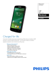
SIMULATED WALNUT FINISH ON VINYL-CLAD STEEL.
GENERALe
ELECTRIC
RECORD SERIAL NO.
Per some state laws. and in the event service should be required. you may need both Model and
Serial Numbers to identify your transceiver. Record the Serial Number (located on the back of the
cabinet) in the space below.
MODEL NO. 3-5875A
RECORD SERIAL NO.
.-
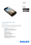
MODEL
3-5875
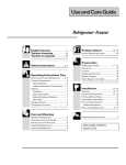
From General Electric. . . SSB-Single Side Band "SUPER BASE" (!) - a full feature Citizens Band
Transceiver base station for operation on all 40 AM channels, and 80 SSB (single sideband) channels, designed for use in home
with 120-volt AC power. . . or truck and camper type of vehicles with 12-volt DC power. Phase Lock Loop (PLL) circuitry
electronically synthesizes all 40 channels. No additional crystals needed. Designed for the serious CB'er . . . with top of the line
performance and loaded with features.
INDEX
.
.
.
General Information . . . . . . . . . . . . . . . . . . . . . . . . . . ..
Base Antenna Systems. . . . . . . . . . . . . . . . . . . . . . ..
Mobile Antenna Systems. . . . . . . . . . . . . . . . . . . . . ..
. Supply the Power (120-volt AC or 12-volt DC)
.
Operating
Controls.
. . . . . . . . . . . . . . . . . . . . . . . . . ..
.
4
Operating Instructions. . . . . . . . . . . . . . . . . . . . . . . . .. 8
Signals - "10 Codes" . . . . . . . . . . . . . . . . . . . . .. 9
Mobile Installation Instructions.
. . . . . . . . . . . . . . . . . 10
. "Q"
4
5
5
.
. Schematic. . . . . . . . . . . . . . . . . . . . . . , . . . . . . . . . . . ..
6
.
Service/Warranty.
11
. . . . . . . . . . . . . . . . . . . . . . . . . . . . . 12
CB FEATURES
. PROGRAMMABLE ELECTRONIC DIGITAL CLOCK
MANUAL POWER ON or OFF
FUNCTION LIGHTS
MODULATION/SWR METER
RFIS METER
SWR CALIBRATION control
.
.
.
.
.
. AWl LIGHT: Antenna Warning Light
. LED (light emitting diode) CHANNEL READOUT
. BRIGHTNESS control
. ON-THE-AIR light
. DUAL SPEED CLARIFIER controls
.
RF GAIN control
. SQUELCHITONE/VOLUME controls
. SWITCHABLE ANL (automatic hois!"1limiter)
. NOISE BLANKER switch
. MICROPHONE POWER control
. SPEECH COMPRESSION switch
. 3-WAV PAlCB switch
. DUAL ANTENNA JACKS: to connect omni and beam type of
antennas or a dummy load.
. JACK FOR: PA SPEAKER, EXTERNAL SPEAKER, SCREW ON
TYPE MIC, AC AND DC POWER CORDS.
. WARNING: TO PREVENT FIRE OR ELECTRICAL SHOCK HAZARD,
DO NOT EXPOSE THIS PRODUCT TO RAIN OR MOISTURE. BEFORE
CONNECTING ANY WIRES OR INSTALLING YOUR CB, PLEASE
READ ALL INSTRUCTIONS.
2
r
FCC LICENSE REQUIREMENT
Do not transmit with your CB unit without an FCC(Federal Communication Commission) Class D Citizens Radio Service
License, or temporary permit.
Youmust applyfora license by mailinga completed FCC Form505to
the FCC, GETTYSBURG,PA. 17326.
At the time this User's Guide was published, no fee for Class D
Licenses was required. This is, of course, subject to change in the
future.
You may use Form 555-B as a temporary permit whileyour regular
Form505applicationis beingprocessedbythe FCC.
.
Transmittingwithouta license or temporary permit is illegal,but you
can listen to (or monitor) all channels without a license. You are
required to be familiar with and understand Part 95 of the FCC
Rules when transmitting.
General requirements for an FCC license are that you must be 18 or
over and a U.S. citizen. Anyone 12 or over in your household can
operate the CB as longas the FCCrules and regulationsare followed.
Your FCC station license willshow your call "letters" (or "sign").
Five or more units may be operated under a single FCC station
license. Ifyou plan to have more than fiveunits, specifyquantityon
FCCForm505.
.
FORMS PACKED WITH CB
. FCC Form 505 license application.
. FCC Form 555-B temporary permit.
. FCC Rules and Regulations, Part 95.
!
SPECIFICATIONS
GENERAL
CHANNELS: AM-40 channels. PLL digital logic channel synthesizer
circuitry. 40 USB and 40 LSB channels.
OPERATING TEMPERATURE RANGE: -30° to +50°C. Thermister
controlled frequency generating crystals to reduce transmit frequency
variation over wide temperature ranQe.
POWER REQUIREMENT: Consumption - 34.5 watts. Current drain 2.5 amps (Max at 12 watts PEP) at 13.8-volt DC.
PA/AUDIO POWER OUTPUT at 10% THD: 3.5 watts.
POWER SUPPLY: 12 volts DC nominal (positive or negative ground),
or 120 volts AC - 60 Hz.
INTERNAL BURNOUT PROTECTION: Componentfailure protection
for min. of 5 minutestransmitting with open, shorted, or loose antenna.
MICROPHONE:
Dynamic with push-to-talk
switch, 500-ohm.
BUILT-IN SPEAKER: 8 ohms impedance, 60 x 90 mm (3'h") in size.
SEMICONDUCTORS: Integrated circuits, transistors, FET (field
effect transistor), diodes, and 2 crystal filters
- one
in the AM IF and
one in SSB IF.
Crystal filters differ from LC or ceramic filters in that they are more
selective and reduce unwanted incoming signals.
TRANSMITTER
RECEIVER
MAX SENSITIVITY: .3uV AM, .2uV SSB (to produce 500mwAudio
Output Min.)
CLARIFIER RANGE: :t 1000-2200 Hz.
FREQUENCY RESPONSE~400 Hz to 2.5 kHz.
FREQUENCY COVERAGE: 26.965 to 27.405 MHz,40 channels AM,
and SSB 80 channels.
TRANSMIT POWER OUTPUT: 4 watts maximum as limited by FCC
Regulations at 13.8 volts DC (PEP 12 watts max SSB).
ADJACENT CHANNEL SELECTIVITY: Min 60 db.
f
CONNECTORS: External speaker jack 3.5 mm (8 ohms impedance).
Two SO-239 type antenna receptacles to match PL-259 coax plug (50
ohms impedance). PA Speaker Jack 3.5 mm (8 ohms impedance).
12-volt DC power jack, separate power cable that allows easy disconnect. MIC Jack. AC power jack.
IMAGE REJECTION: Better than 55 db.
IF FREQUENCIES: SSB: 10,695 MHz, AM. 1st: 10,695 MHz. 2nd:
0.455 MHz.
RF GAIN CONTROL: 25 db nominal.
-
AGC (less than 10 db Audio change from 3 uV 10,000 uV RF):
Min. 70 db.
FREQUENCY COVERAGE: 26.965 to 27.405 MHz; 40 channels AM,
and SSB 80 channels.
MODULATION:Capableof 100%. Factory pre-set limit, 85-100%.
TRANSMITTED HARMONIC & SPURIOUS SUPPRESSION(below
carrier): Min. 62 db.
FREQUENCY ACCURACY: :t.001%.
CARRIER SUPPRESSION: Better than 40 db.
UNWANTED SIDE BAND SUPPRESSION: Better than 50 db.
ALL MEASUREMENTS TAKEN AT 25°C NOMINAL
AND 13.8 VOLTS DC.
3
-
I
I
GENERAL INFORMATION
ANTENNA SYSTEMS
CB's MANY USES
ANTENNA SYSTEMS
23 channels of Citizens Band (two-way) Radio were approved by the
FCC in 1958 and expanded to 40 channels in 1977 to be used by
private citizens for personal and business communications.
For best reception and transmission, your CB transceiver should use
an antenna especially designed for a frequency of 27 MHz. Antennas
are purchased separately and include installation instructions.
CB radio is easy to understand and operate. There is nothing technical
you must know. . . no more than what it takes to use a telephone or
operate any standard AM or FM radio.
Numerous types of CB antennas are available that range from
emphasis on ease of installation to emphasis on performance. Often
the difference in performance between many of the antennas is
modest.
When communicating
with your CB, always be brief, never use
profanity (against the law and carries severe penalties), and follow the
FCC rules as outlined in Part 95.
Here are some of the many uses for CB radio:
.
.
Personal or Family. Keep in touch between your car, home,
friends, and neighbors.
Hunting, Fishing, or Camping. Talk between campsites, to fishing
boat, boat-to-shore, hunting parties, or camper-to-camper.
. Travel
and Vacation. Request directions when you are lost on the
highway, need help to repair a flat tire, or to report an emergency.
.
.
.
.
Security. Some cities have established a Volunteer CB Patrol that
provides concerned citizens with a communication line t6 local
police for reporting suspicious or criminal activity.
Business
Use. Save time and extra trips: call your office for
messages.
Sales and Service. Save valuable time by using CB for those quick
contacts or confirming appointments.
~
Your transceiver has two standard antenna connectors: type SO-239
(located on rear panel) for easy connection to standard PL-259 coax
plugs. If the coax antenna cable must be made longer, use coax cable
with impedance of 50 ohms, frequency ratings for 27 MHz, and use
only enough cable to suit your needs. This will insure a proper
impedance match and maximum power from the transmitter to the
antenna.
BASE STATION ANTENNAS
When using this CB transceiver as a base station, any Citizens Band
ground plane, beam, dipole, or vertical antenna may be used. The
range of the transceiver depends basically on the height of the antenna. Whenever possible, select the highest location within the FCC
limits.
NOTE: You can connect 2 antennas to your CB, or 1 antenna and one
dummy load. See Accessory Order Form.
Truckers, Deliverymen,
Farmers, Ranchers, or Construction
Crews. Whether you're calling for road and traffic conditions, farm
tractor to house, or coordinating work crew activity, two-way radio
can play an important role.
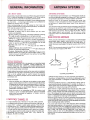
SINGLE SIDEBAND
Conventional 40-channel (AM) units operate on a
consisting of three parts: CARRIER, UPPER
LOWER SIDEBAND. Both UPPER and LOWER
located on either side of the CARRIER and contain
tion (all the audio) being transmitted.
transmitted signal
SIDEBAND,
and
SIDEBANDS are
identical informa-
Single sideband transmitters cancel out the carrier and one sideband,
and devotes the final stage to transmitting only one of the sidebands.
That is, all the wattage would be used to transmit the selected
sideband. This results in perhaps twice the useful transmit range of
conventional AM.
Points of Interest:
1. Since the operator of an SSB unit has the option to select either
upper or lower sideband on which to transmit for each CB channel,
he effectively has twice as many transmission paths or "channels"
as an AM operator. (Note: AM does overlap or interfere with SSB
on the same channel, so the 80 SSB "channels" are not new,
independent transmission paths.)
2. Since the carrier is not transmitted on SSB, the receiver must
recreate a "carrier" to en'able demodulation. Since this recreated
carrier must be accurately on frequency, a "clarifier" control is
necessary to fine-tune.
EMERGENCY
CHANNEL 9
A major beneficial use of CB radio is for public safety purposes.
The Federal Communication Commission has issued "call signs" that
include "0911" numbers to public safety agencies. These numbers
coincide with the "911" telephone numbers coming into greater use by
public safety agencies (state police) for telephone communications.
The call signs for state-level agencies use 3 letters and 4 numbers,
with the second and third letters being the official Post Office state
abbreviation, and then the number "0911" (e.g., KMO-0911 for
Missouri, KIL-0911 for Illinois).
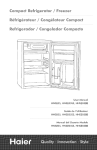
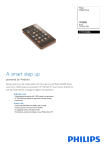
GROUND PLANE
BEAM
I
,I
COAXIAUCOLlNEAR
GROUND PLANE antenna is the most commonly used antenna for
base stations. It is fairly effective, omni-directional, lightweight, easy to
mount, and economical. It is designed for medium-long range communications.
COAXIAUCOLlNEAR
antenna is a high-efficiency radiator with improved omni-directional characteristics. It provides an effective increase in power when compared to a regular ground plane antenna. It
is designed for medium-long range communications.
BEAM antenna is highly directional and must be used with a rotor
unless you are communicating with a fixed station. Since it is directional, it greatly reduces noise and interference from all other directions. The increased forward gain and the higher front-to-back ratio
results in an effective power gain many times that of a standard ground
plane. It is designed for long range communications.
Whatever type of antenna you choose, ground the antenna mast and
connect a lightning arrestor to the coaxial lead-in. This will protect your
system and reduce static interference. Follow all safety instructions
when installing base station antenna.
Use coaxial cable rated for the 27 MHz frequency when connecting
your base station antenna to the transceiver. Use proper connectors
and terminate them well when installing the antenna system. Usually
RG-58/u cable is adequate up to 50 feet. If installation requires over 50
feet of cable, use RG-8u type to reduce any in-line signal loss.
Antenna cable can also act as the antenna, so keeping length to
minimum not only reduces signal loss from cable, but also pick-up of
static signals.
4
j
MOBILE ANTENNAS
ANTENNA PERFORMANCE
Whatever type antenna you choose, a good ground is important. Be
sure you have metal-to-metal contact at the point where the antenna is
mounted on the vehicle. Painted surfaces should be scraped (at least
a small area) or use a "star" washer to assure metal-to-metal contact.
This will provide protection to you system and reduce static interfer-
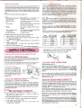
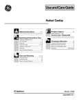
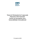
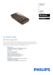
Antenna performance
may be peaked (refer to instructions
included
with antenna) using SWR (standing wave ratio) meter as explained on
page 7. Most antennas are factory-tuned, but this adjustment may
improve antenna efficiency. An SWR reading below 3:1 is desired, as
this indicates that over 75% of the transmit power is broadcast into the
air. The rest is "reflected" back into your CB and dissipated as harmless heat. See chart below. An SWR :>f2:1 or below is good; 2:5 or
even 3 is usually not user noticeable or significant.
ence.
.
Some of the mobile antennas available are:
.
.
Advantages
Some performance compromise, but
use single antenna on vehicle.
No installationrequired, some perforMagnetic Mount
mance compromise.
Gutter Mount
Easy to install, directional,and some
performance compromise.
Permanent installation,high antenna
. Rooftop
location.
. TwinAntennas Mirror Performance (specialized application)
or Cab Mount
and appearance appeal.
No Ground Plane
For use on boats
General rules for best CB mobile antenna performance:
1. Mount antenna on vehicle as high as possible.
2. The higher percentage of antenna length mounted above rooftop,
the better the performance.
3. Center antenna in middleof selected location(Le;,trunk,gutter,or
roof).
4. Install antenna cable line away from noise sources (ignition
system, gauges, etc.).
5. Besure to mountantennawitha good metal-to-metal
ground.
Type
CB-AM-FM Combination
with CB splitter
.
.
(
SUPPLY THE POWER
Power for your CB transceiver
)
NOTE: Mounting the antenna in a non-metal boat will require an
installation of a "ground plane" or special antenna. Grounding can
either be a metal hull or a ground made of tinfoil on copper sheeting,
and cover an area of 12 square feet or more. The unit must also have
an adequate ground.
Warning; Operating unit without attaching antenna, or with a
broken antenna cable, will result in low and possibly no power
output.
Select the antenna that best fits your use or installation needs. See
order details on enclosed ACCESSORY ORDER FORM.
SWR
OUTPUT POWER
READING TRANSMITTED
100.0%
1:1
1.3:1
98.3%
96.0%
1.5:1
93.3%
1.7:1
2:1
89.0%
SWR
OUTPUT POWER
READING TRANSMITTED
3:1
75.0%
64.0%
4:1
5:1
58.0%
49.0%
6:1
33.0%
10:1
3. Use pliers to firmly squeeze CLAMP around the wire so the WIRE
STRANDS make a good contact with the ADAPTER.
4. Slide INSULATOR down to cover the C!-AMP.
BEND
ADAPTER
can be supplied in two ways:
/"
120-VOLT AC OPERATION (Base)
P'"
INSERT
Use 120-volt AC power for BASE STATION operation. Plug AC power
cord into 120-volt AC jack located on rear panel and the other end into
a working 120-volt household outlet.
This unit may also be operated on 12-volt DC from a motor vehicle
using the power cord provided and DC input jack. See below.
POWER
battery
120.vOl
~
T AC POWER
COAO
'rw;~~~~~'~~~~~~8~~t~;Z:;~:;'A'"
.
You may prefer using the ignition accessory terminal on the fuse
block, so transceiver will automatically turn off when ignition switch
(key) is turned off. If connection is made at fuse block, be sure to use
fused side of terminal.
NEGATIVE GROUND WIRING CONNECTION
AC POWER CORD FROM UNIT
This transceiver is designed for 12-volt DC use with either negative or
positive ground electrical systems. Most U.S. and foreign-made cars
and small trucks made since 1956 use a negative ground system,
while some older cars and newer heavy "18-wheeler" trucks have a
positive ground system.
DC POWER SOLDER LESS CO.NNECTOR
For convenient wiring, the RED wire can be used in 3 ways:
With ADAPTER (included separately - connect as shown) for
attaching to fuse block on cars.
. By bending ADAPTER PIN out for inserting into GM type of cars.
. Or use WIRE STRANDS to wrap around power connection.
1. Insert fused wire into INSULATOR.
2. Twist WIRE STRANDS back on its own wire and place into
CLAMP side of ADAPTER.
.
power cord to:
lighter, or directly to the battery. Usually the most convenient location
for connecting power is either to the fuse block (normally located
under dash at left or right side of steering column), or directly to the
If AC power is interrupted for
more than a few seconds, the
a.m. or p.m. indicator on the
DIGITAL CLOCK DISPLAY will
blink as a reminder that CLOCK
(and TIMER) must be reset to
. correct time.
DISCONNECT
Connect
POWER CONNECTIONS
Fuse block, solenoid, voltage regulator (marked "BA TT"), cigarette
OUTAGE
12-VOLT DC OPERATION (Mobile)
LOCATING
If your (-) battery terminal is connected to the car's motor block, then
the vehicle is a negative ground system. Connect red wire (with in-line
3-amp fuse holder) to POS. (+) side of battery, or any of the locations
previously mentioned. Connect the black (or brown) wire to any
grounded, NEG. (-) metal part of the vehicle.
CAUTION: Be sure black (or brown) wire is connected to metal, as
many underdash and side-paneled parts are made of non-conductive
plastic. Good ground is essential for satisfactory operation.
WARNING:Donot operateunitbeforeinstallingantenna.Besure
CB is in the OFF position when making power and antenna
connections.
This CB has built-in protection against transistor burn-out in
case you transmit (5-minute continuous transmit limit)accidentally without antenna connected. Be sure antenna is connected
and the ANTENNAswitch is in the correct Aor B position before
transmitting for the first time.
5
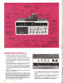
OPERATING CONTROLS
1. LED (light emitting diode) DIGITAL CLOCK READOUT:
Clock operates only when using 120-volt AC power.
.
. Use BRIGHTNESS control to adjust light intensity of readout.
. Depress CLOCK DISPLAY - TIMER or CLOCK SET button,
-
then use TIME SET FAST or SLOW button to change readout.
2. A.M./P.M. INDICATOR:
This clock-timer operates on a 24-hour cycle and the indicator
lights will show when clock is reading a.m. or p.m. time.
.
. If 120-volt AC power is interrupted for more than a few seconds,
the a.m. or p.m. indicator light will blink. Advancing the CLOCK
SET (or TIMER) to correct time will restore clock for normal
operation.
3. MANUAL POWER ON-OFF: Depress to turn CB ON, when
operating on AC or DC power.
4. AUTOMATIC TIMER: While operating on AC power, you can
depress this button and select any a.m. or p.m. time to turn CB
power ON automatically. If this button remains depressed,the CB
will turn on for the time you selected, operate for about one hour.
then turn itself off automatically and repeat every 23 hours. To
stop the cycle or turn the power off sooner, depress the AUTOMATIC POWER button to off (up) position.
6
5. CLOCK DISPLAY: Depress TIMER or CLOCK SET button to
change the DIGITAL CLOCK READOUT or check TIMER DISPLAY.
6. TIME SET: Use FAST or SLOW button to advance DIGITAL
CLOCK READOUT to the a.m. or p.m. time you choose.
IMPORTANT: To advance readout time, either the CLOCK
DISPLAY TIMER or CLOCK button must be depressed.
7. FUNCTION INDICATOR LIGHTS: Show operating modes USB,
AM, or lSB of unit.
8. RF/S METER: Receiving (RX) indicates relative incoming CB
signal strength in "S" units on the upper half scale. Transmit (TX)
indicates relative power output from your CB on the lower half
scale.
9. ANTENNA WARNING INDICATOR: When this light is ON, your
antenna or connecting cable may not be properly connected,
badly mismatched (high SWR), or damaged. This feature works
only if METER SWITCH is set to MOD position and FUNCTION
switch is in AM position.
10. lED CHANNEL READOUT: The lED (light emitting diode) will
indicate 1-40 channels.
11. ON-THE-AIR TRANSMIT LIGHT: The ON-THE-AIR light will be
illuminated only when in TRANSMIT mode.
12. MODULATION AND SWR METER: This meter serves two
functions:
1. Indicates relative modulation (voice) from your CB, but only
when operating in AM position and the METER SWITCH is set
to MOD position.
NOTE: When operating on SSB, use RF/S METER for
modulation reading.
2. Determines SWR for indicating how well matched the antenna
and cables are to your CB. For checking SWR (standing wave
ratio), you must switch to AM position and use METER
SWITCH and SWR CALIBRATION control.
13. SPEECH COMPRESSION: Reduces the dynamic range (difference between loud and soft voice) of signal and allows a higher
average modulation to be transmitted. To transmit normal voice
without overmodulation(FCC requirement),a low modulationaverage must be maintained, resulting in poor talk power. SPEECH
COMPRESSIONraiseslow-level signalsand decreases high-level
signals, which enables a higher average modulation to be transmitted. The normal setting should be used for short range communicationsfor a more natural soundingvoice. Setting SC to MAX
will have its greatest effect on long range transmissions.
14. CLARIFIER
CONTROLS:
Used while in USB or lSB modes to
clear up incoming voice. Turn RAPID knob back and forth slowly.
Stop at the point where the voice is strong and clear, then use
FINE TUNE control.
When switched to AM position, use controls for DELTA tuning.
Set both controls to center position, then adjust (if necessary) to
obtain best reception quality.
15. MICROPHONE JACK: For connecting MICROPHONE. The CB
receiver and transmitter are controlled by the press-to-talk switch
on the MIC. Press switch on MIC to transmit and release to
receive. Hold MIC directly in front of you at a distance of about 2 or
3 inches when transmitting and speaker in a normal voice. Note
space on front of MIC for call sign.
16. ANTENNA A-B SWITCH: For switching between two types of
antennas or dummy load that may be connected to this unit. You
may connect a GROUND PLANE antenna, which is nondirectional, or a BEAM type antenna that is highly directional, for
.. long-range selective communications, or connect both.
17. SWR (standing wave ratio) CALIBRATION: Used to adjust
MODUlATION-SWR METER for checking SWR as follows:
Your CB must be switched to AM position and then the METER
switch must be set to CAl position. With MIC press-to-talk switch
depressed, turn SWR CAl knob until you adjust needle in
METER to SET position. Flip METER switch to SWR position,
meter should read 3 or lower. Release MIC press-to-talk button
and flip METER switch back to MOD position for normal
operation.
CLOCK/CHANNEL BRIGHTNESS: To adjust light intensity of
digital readouts.
19. RF GAIN: Use this control to prevent an overload when receiving
strong signals. EXAMPLE: When RF/S METER indicates more
than three-fourths scale ("receiving" strong local signals), merely
reduce RF GAIN control. Increase RF GAIN control to receive
weak or distant signals.
20. CHANNEL SELECTOR: Rotate knob to select any of the 40
channels available. CB channels are shown in lED READOUT.
IMPORTANT: Channel 9 is reserved for emergency use only.
Note that the cabinet has Channel 9 marked for quick channel
selection.
21. MICROPHONE POWER GAIN: A pre-amplifier circuit is built into
this unit to increase microphone gain. Experiment with control for
the setting that will best suit your individual use.
NOTE: When MIC GAIN is set to maximum, ambient noise
(background conversation) may also be picked up by the
microphone. In high noise situations, low MIC GAIN setting may
produce best results. MIC GAIN is also used to adjust PA loudness.
22. CB/PA SWITCH POSITIONS:
.
PA. For PA operation only, you must have an optional8-ohm
PA speaker connected; then press in the MICROPHONE push
button and talk in a normal voice. PA loudness can only be
varied by the MIC POWER knob. Channel lED will be OFF in
PA mode.
. PAlCB. When not using PA, and MIC switch is released, you
can listen to (monitor) CB transmission through the PA
speaker. Volume is adjustable for CB monitor by VOLUME
control, and PA loudness only by the MIC POWER control.
. CB.
Returns unit to normal mode of operation.
IMPORTANT: Mount PA speaker facing away from MIC and as
far as possible from unit to prevent feedback howl.
23. SQUELCH AND TONE: Turn SQUELCH counterclockwise to
activate CB receiver circuit and a hissing sound will be heard.
Slowly rotate SQUELCH clockwise until hissing just stops.
NOTE: This adjustment is to eliminate annoying static atmospheric noise (hissing) and weak background signals. Turning
SQUELCH clockwise increases the signal strength needed to
activate CB receiver section, and you can receive only strong,
clear signals. Therefore, setting SQUELCH beyond the point
where hissing just stops may prevent reception of weak CB
signals. Set SQUELCH for your personal preference.
Turn TONE to suit your listening taste.
24. AUTOMATIC NOISE LlMITER: Use ANl switch to reduce noise
from motors or other electrical interferences.
25. NOISE BlANKER: If ignition or other pulse type interference is
still present, even with ANl in ON position, use NOISE BlANKER
to reduce excessive interference. When no noise is present, set
NOISE BlANKER and ANl switch to OFF for clearer reception of
distant stations to get maximum sensitivity.
26. VOLUME: Rotate clockwise to increase loudness.
27. FUNCTION SWITCH: To select operating mode, lOWER SIDE
BAND, UPPER SIDE BAND, or AM standard 40-channel band.
MIC HOOK
Alternate Mic mounting system. Screw on back of MIC and use like
"cup hook" method.
18. METER SWITCH: Used to select METER position for reading:
MOD: Modulation (refer to 12)
CAl: Calibrate METER for checking SWR in AM position.
SWR: To read SWR (refer to 17)
.
.
.
7
J
OPERATING INSTRUCTIONS
IMPORTANT: Make sure antenna, power source, and microphone are connected before you operate.
TO RECEIVE
1. Connect MICROPHONE and depress MANUALPOWER ON-OFF
push buttonto turn unit ON. Rotate VOLUMEto increase loudness.
You cannot transmit or receive if MICROPHONEis disconnected.
2. Set CB/PA switch to CB position.
3. Set ANTENNA
switch to the antenna connected,
A or B.
4. Turn CHANNEL SELECTOR to any of the 40 channels as indicated by the LED readout window.
5. Select the desired operating FUNCTION, either AM, LSB or USB.
When it is placed in AM, the unit transmits and receives as any
conventional transceiver.
SSB is only intelligible if both you and the other operator are in the
same USB or LSB position. When transmitting, the sideband you
select (LSB or USB) will interfere with AM stations on that channel.
They also hear you, though not intelligibly. When receiving LSB or
USB, use the RAPID and FINE TUNE CLARIFIER controls.
6. Turn SQUELCH counterclockwise
to activate the receiver circuit,
and a hissing sound will be heard in the speaker. Slowly rotate
SQUELCH clockwise until the hissing just stops.
The RF/S METER reading will indicate incoming signal strength.
Experiment with SQUELCH setting to become familiar with the
signal strenoth of unit ("S" units on r.leter) which overrides
SQUELCH setting. To receive only strong, clear signals, set
SQUELCH to high position, but to monitor all transmissions, set it
to minimum position. (When weak or no transmissions are being
received, continuous atmospheric noise will be heard. If noise is
objectionable, turn SQUELCH to point where noise just stops.)
7. Turn TONE control to suit your listening taste.
8. Use NOISE BLANKER, ANL, or RF GAIN features as requir~d.
ANTENNA WARNING INDICATOR
If you have
When this
connected,
only in the
trouble in your antenna system, the AWl light will glow.
light is "ON" your antenna or connecting cable is not
badly mis-matched (high SWR), or damaged. AWl works
AM position and METER switch on the MOD position.
AWl light will go on when SWR reading is between 3:1 and 7:1 or
worse, depending on antenna installation. AWl will also light on some
channels or all channels when using a magnetic antenna. This is
normal because SWR reading with magnetic antenna often exceeds
3:1. If AWl lights on some channels but not on all channels, the SWR is
high on only those channels. As long as reception and transmissions
are acceptable, no action need be taken by the user. Some antennas
(in a particular location) are just not tuneable below a 3:1 SWR
reading.
NOTE: In some situations, the combinations of a particular CB,
antenna, plus the antenna mounting location will result in a low AWl
threshold below 2:1 SWR. Transmitting with AWl lighted does not
degrade performance. If you have this combination, check SWR.
Tune antenna for the most frequently used channel for reading below
2:1 (no AWl light).
DIGITAL CLOCK READOUT
The Digital Clock Readout has two functions. It displays the regular
a.m. or p.m. time and the TIMER setting.
SET THE TIME
In regular operation, the Time Display shows the a.m. or p.m. time. To
set the time:
1. Depress the CLOCK SET push button.
2. Experiment with the clock display by pressing and holding down
first the FAST and then the SLOW TIME SET controls. Become
familiar with the speeds involved and practice setting the clock to
different times.
Use the FAST button to change hours and press the SLOW button
as you approach the a.m. or p.m. setting you want.
TO TRANSMIT
1. Wait until the channel you selected is clear. Hold the MICROPHONE directly in front of you at a distance of about 2 or 3
inches. Now, press in the MICROPHONE push button and talk in a
normal voic.e to transmit your message.
NOTE: Do not shout into the microphone or hold MIC against your
mouth, to prevent over-modulation. Over-modulation is referred to
as sounding like "marble mouth" (garbled).
2. Flip METER switch to MOD position, then read your modulation in
the MODULATION/SWR
METER. METER reading will increase
with your voice loudness.
3. Use SPEECH
COMPRESSION
average modulation
and MIC POWER to increase
Notice that the clock operates on a 24-hour cycle. The A.M. INDICATOR light to the left will show whether the clock is reading a.m.
(light ON) or p.m. (light ON) time.
3. Depress the CLOCK SET control to OFF (UP) position.
SET THE TIMER
To display the TIMER setting, depress the TIMER SET push button.
1. Use FASTand/or SLOW push buttons to set the display to the a.m.
or p.m. time you choose. The AUTOMATIC POWER time is now
"entered" into the timer memory.
2. Release the TIMER SET push button. The correct time is once
again displayed.
as desired.
4. TO RECEIVE, release the microphone push button.
5. The NOISE BLANKER, ANL, CLARIFIER, VOLUME, SQUELCH,
TONE, RF GAIN, and SWR CAL control settings have no effect
when transmitting.
6. To turn the transceiver off, depress the MANUAL POWER
ON-OFF button to the "UP" position.
NOTE: Do not press and hold MIC switch without talking, as you
are sending signal with no information (modulation) and are
causing illegal interference to other users.
AUTOMATIC POWER (TIMER) OPERATION
1. To have the unit turn on automatically at a preset time, set the
TIMER as described above.
2. Depress AUTOMATIC (AUTO) POWER push button.
3. Turn VOLUME knob to increase loudness. The CB will automatically turn on at the time you have set and will turn itself off after
about one hour. To turn CB off sooner, depress AUTOMATIC
POWER push button to OFF (up) position.
Your CB has a 24-hour timer. When left in AUTOMATIC
POWER
mode, it willturn itself on, stay on for an hour, turn itself off, and
turn on again at the same time the following day.
8
.
PUBLIC ADDRESS (PA) FEATURE
EXTERNAL SPEAKER JACK
Use as a P A amplifier with optional8-ohm PA speaker (see Accessory
Form) as follows:
1. Connect 3.5 mm plug from PA speaker to the PA jack located on
An optional 8-ohm speaker may be used. With remote speaker
plugged into 3.5 mm EXT.SP. jack, the internalspeaker is automati-
the cabinet back.
2. Turn unit to ON position. Set CB/PAswitch to PA position. .
NOTE: While in PA or PNCB mode, all audio output is directed to
the PA jack and the internal speaker is disconnected.
"Q" SIGNALS
Many SSB operators use "Q" signals which are different than
standard AM"10" Codes as listed below:
QRG
QRH
QRL
QRM
QRN
QRT
QRV
QRX
QRZ
QSB
QSL
QSM
QSO
QSP
QSY
QTH
QTR
What is my exact frequency? Yourexact frequency is Does my frequency vary? Yourfrequency varies.
Are you busy? I am busy.
Is my transmission being interfered with? Your transmission
is being interfered with.
Are you troubled by static? I am troubled by static.
ShallI stop sending?Stop sending;or, I willstop sending;
or, End of contact.
Are you ready for traffic? I am ready for traffic.
This station is goingoffthe air (or on listening-onlystandy-by).
Who is calling me? You are being called by Are my signals fading? Yoursignals are fading. ..
Can you acknowledge? I am/will/canacknowledge.
Shall I repeat? Please repeat.
Can you communicate with I can communicate withWillyou relay to I willrelay to Shall I change frequency? Change frequency to What is your location? Mylocationis What is the correct time? The correct time is -
cally disconnected.
THE "10 CODE"
You will often hear 10 code used in CB communications,
like "10-4" or
"10-7." It is not necessary to use 10 codes on CB; just talk as you
would on the telephone. Some people enjoy using 10 codes. To help
you understand them, shown below are Standard Condensed Radio
Codes used by Associated Public Safety Communications Offices
(APCO). Local uses may vary.
Many CB'ers also use 10 codes which are different from APCO, and
the most noticeable difference is that 10-36 is the code for "correct
time." Use of the 10 codes is not recommended
for emergencies.
when using Channel 9
"APCO 10 CODE"
10- 1 - Signal weak
10- 2 - Signal good
10- 3 - Stop transmitting
10- 4 - Affirmative (OK)
10- 5 - Relay (to) 10- 6 - Busy
10- 7 - Out of service
10- 8 - In service
10- 9 - Say again
10-10 - Negative
10-11 - On duty
10-12 - Stand-by (stop)
10-13 - Existing conditions
10-14 - Message information
10-15 - Message delivered
10-16 - Reply to message
10-17 - Enroute
10-18 - Urgent
10-19 10-20
-
10-21 10-22 10-23 10-24 10-25 10-26 10-27 10-28 10-29 10-30
-
10-31 10-3i 10-33 10-34 -
(In) Contact
Location
Callby phone
Disregard
Arrived at scene
Assignment completed
Report to (meet)Estimated time of arrival
Ucense/Permit
information
Ownership information
Records check
Danger/Caution
Pick UpUnits needed
Specify Number/Type
Help me quick
Time
9
1
I
i
f
MOBilE INSTAllATION INSTRUCTIONS
Your transceiver is designed primarily as a base station, but is versatile enough to function as a mobile unit in vans, campers, or other
recreational vehicles. The bracket and hardware packed in the carton
allow you to install the unit for mobile operation yourself.
The bracket may be used to install the unit under a kitchen cabinet or in
some other desirable location selected by you.
3. Use MOUNTING BRACKETS as template for drilling Vs-inchholes.
Mount brackets with SELF-TAPPING SCREWS.
4. Install MICROPHONE HOLDER on either side of CB and mount it
in horizontal or vertical position to suit your own preference.
5. Use easy-grip THUMB SCREWS to secure the CB to MOUNTING
BRACKETS.
NOTE: If possible, avoid mounting transceiver in heater or
aIr-conditioning air-flow path.
MOBilE INSTAllATION
Install unit as shown in REAR PANEL sketch. Tools required are a
#30 drill (Vs-inch) and a Phillips head screwdriver.
1. Mount CB so all controls are conveniently available to you (the
operator) without interfering with movements for safe driving
of your vehicle.
2. Be sure all cables are clear of brake, clutch, and accelerator.
6. Connect antenna plug to antenna jack on rear of unit (see
ANTENNA section for further information).
7. Connect DC power plug to 13.8-volt DC jack located on rear of unit
(see SUPPLY THE POWER section for further information).
IMPORTANT: When CB is connected to 13.8-volt DC power
source for mobile operation, the digital clock will automatically be
disconnected.
3.5 mm PLUG TO
EXTERNAL
SPEAKER
FADING
GENERAL CB INFORMATION
The following is what you may expect once your CB transceiver
properly connected.
is
.
The effective range depends on several distance factors: the
antenna used, its height, terrain (city with tall buildings or other
obstructions, over water, flat land or hills), weather conditions, and
the number of other CB'ers on the same channel at the same time.
.
Tall buildings, such as found in major metropolitan
will reduce distance greatly.
.
Weather and atmospheric conditions such as lightning, sun spots,
and other electrical interference will result in strong static and limit
TRANSMIT and RECEIVE range.
.
Skip (long-distance communications) is possible when CB signal is
reflected back from ionized atmosphere and should be avoided per
FCC rules.
.
Heavy channel congestion,
decreases range.
areas, and hills,
like Ch. 19 in most large
cities,
The rel2tive range under normal and favorable conditions is shown
below. This should not be taken as a minimum range of performance,
but rather as what can be expected from Class "D" stations under
favorable cicrumstances and proper antenna mounting.
Mobile to Mobile: 1 to 5 miles on land and up to 10 miles across
water.
Base to Mobile: 5 to 10 miles on land and up to 15 miles across water.
Base to Base: Up to 20 miles, depending on type of antenna, height,
and terrain.
RECEIVES ONLY ONE SIDE OF CONVERSATION
This is not unusual on CB broadcasts
-
the distance between the two
transmissions you are monitoring may put one out of your range, or
signal strength may be different from a mobile station versus a base
station.
10
Fading occurs while driving away from another mobile or base CB
while communicating. Fading sounds like you're picking up every
other word or background noise level increases while voice level
decreases. Also, stronger signals will override your communications.
A CB operating half way between your two mobiles (MOBILE 1 and 2)
have 4 times the signal power compared to your mobile. This is often
referred to as "walking over you."
NOISE
Some noise is to be expected and is normal. There will be a
higher level of background noise when used as a mobile CB
transceiver and the car is running. If this noise becomes objectionable (which is caused by the vehicle's alternator, generator, spark
plugs, windshield washer, and other electrical systems), a noise
suppression kit may need to be installed. These are available from
two-way radio stores, or you may have a servicer do the installation.
Noise from the alternator or generator will create a whining, highpitched sound and will vary with engine speed. Spark plugs and
ignition noise will show up as a popping sound and can also vary with
engine speed.
To tell the difference between noise created bythe ignition system and
noise created by the generator, start the vehicle and race the engine.
Now turn the engine off. If the noise stops immediately, you have
determined that the ignition system is at fault.
..
Noise which stops a few seconds after the ignition is turned off, is
caused by the alternator or generator.
Noise can be caused by electrical interference from spark plugs and
ignition cables. Most late model vehicles have resistance high tension
ignition cable and resistive spark plugs supplied as standard equip"
ment. This eliminates the need for spark plug suppression. If not\
supplied, kits are available from automotive supply dealers.
..1
I