1
TWO-SEATER SZD-50-3 "PUCHACZ"
GLIDER
F L I G H T
Issue 3
~
MAN U A L
Dece~ber
1985
This instruction is the part of the
Airworthiness Cartific~te of the glider of:
Serial No B__2057
........ .
G-CHEP
Reg.No ••••••.•••••
ThiS is the translation of the original
Polish Manual approved by Central
Ad~1n16tretion of Civil Aviation jpages 1-3
to5-f7/
Date
Translated by.
Wieslaw Staf1ej. O.Sc.
J
UruJ<.:OWPT Uielako-Diala /ZOOO/466/Hz'
r
-
1-2
-
-
50-3
FM3
1-3
-
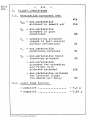
CON TEN T S
1 i)
LIST OF REVISIONS
2.
LIMITATIONS
2.1. Permissible airspeeds
OPERATI~~
2 •. 2. Limit load factors
2.3. Colour markings of airspeed
indicator dial
2.4. Towing cable safety link
2.5. Restrictions
2.6. Masses
2.7. Permissible range of c.g. location
2.8. Table of weighing the glider
2.9. Graphical checking of c.g.location
2 10 o Placards and inscriptions.
PERFORMANCES
GLIDER OPERATION
401. Pre-flight inspection
4.2. Cockpits and their arrangements
4.3. Service before take-off
4.4. Controlling
0
3
0
4n
4.5. Aerobatics
4.6. Danger and e~rgency conditions
4.7. Assembling and disassembling
f.~ _ _ _ _ _ _ _ _ _ _ _ _ _ _ _ _~ _ _ _ _ _ _ _ _ _ _ _ _ _ _ _ _ _ _ _ _ _ _ _ _ _ _ _ _ _ __
Oruk:OWPT Bielako-Diala /1.000/466/132
-
5.
1-4
-
DRAWINGS AND DIAGRAMS
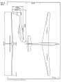
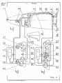
1. 5Z0-50~3 "PUCHACZ" glider
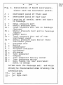
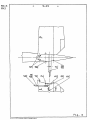
2. Insta~t1on of board instruments
Glider with two instrument panels
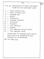
2a.lnstaIBtion of board instruments
Glider with one instrument panel
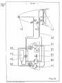
3. Wiring diagram of electric turn
indicator
4. Speed polar
5. Wings-to-fuselage assembling
6. Assembling of hori%ontal tailplane
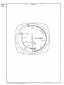
7. Colour markings of airspeed
indicator dial
APPENDIX
Individual loading plan
50-3
FM3
-
50-3
FM3
1-5a
-
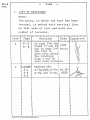
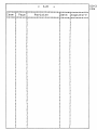
1_ LIST OF REVISIONS
NOTE;
The place, in which the text has been
revised o is marked with vertical line
on left side of text and with the
number of revision.
I
2
I
12-3V1385
'J Replaced with
1
I
I
1
I
I
2-4
2-5
. 6-2
!
~
2 - 3a/1385, 2-4a, 14 " 09. I
2 - 5a and 6-2a. ~ 1992. :
J
I
I
I
t
i
!
J
1
I
I
l
I
I
I
I
I
J
I
I
I
I
I
I
I
t
I
I
I
I
I
I
I
I
J
I
I
I
I
I
I
I
I
I
I
I
I
I
I
1
J
,
I
I
I
a
I
I
,
•
I
,
I
I
J
,
i
I
I
I
•
I
t
t
I
i
I
1
V
1
I
I
I
a
I
1
I
I
a
Q
;
2
1
r
,
Druk:OW PT IHc:lsko-Biala /2.000/466/ '62.
I
J
I
I
J
J
J
a
I
•.
I
l
j
-
-
==:t':::~·==;=.=~:=:::::==s.·;:::=-:::=.·=r=:=
Item : Page ~
: 2::1"1::: ~=u::t
r=-
QI.:a
,J
I
I
I
I
f
I
I
J
1
•
I
J
r
: Date : Si.gnat u r e
'i
.=:ZJ.:.:I::
:;r"f
' I
!
,
•
I
I
I
t
I
J
'r
a
a
I
I
I
:
I
1
I
II
I
ta
i
I
J
r
' 1
•I
II
J
I
I
i
f
t
I
I
I
I
I
I
J
I !
!
t
J
1
J
J
Revision
i
FM3
=::r·:::t:::~;:::::::l::::=:C-:;Z :=-=:=:.::::.;!:n===::r.r:
a:n;:~ ::: :&::n:::..;:::::;: J:;f ::t:=c l;; m ::: cc: ~ :a':Z: :::I Xl =
I
I
I
I
1
&«
I
==
50-3
;
"
e
I
1
1I
f
I
I
I
J
JJ
I
I
a
I
I
I
i
I
I
~
J
I
J
J,
'J
•
I
1
I
J
I
1
'
r1
I
J
1
D
i
I
I
I
I
I
I
I
J
I '
I
I
3
I
1
I
•
I
I '
I .
"
I
I
;
I
I
I
I
I
I
I
I
I
i
I .
I
I
J
!
I
I
I
I
I
t
t
I
I .
•
I
1
I
I
J
f
I
J
1
J
I
I
!
I
I
J
,I
•
! ;
I
I
f
I
i
I
I
I
1
I
J.
I
I
I
1
I
l
I
I
D
B
i
I
I
J
I
I
J
J
I
I
I
I
I
I
~
I
:
I
' I
' I
i
I
'
J
' J
t
I
t3 .t::n:::::::::::::::.:::;: ::::":0 ~
50-3
FM3
2.
- 2-1
FLIGHT
LIMITATIONS
_.....-.-_ ................
_-----_
-
...
2.1. Parmiesibl! air!peeds lAS:
VNE - max. permissible
airspeed in smooth air
-
kts
116
~ax.perN1s6ible
airspeed in gust
conditions
-
~ano~uvring
airspeed
jspeed of full control
surface deflection/
-
ma~.permissibla
aerotowing airspeed
- max. permissible winch
launching airspeed
- maxopermiasible
airspeed for. extending
and flight ~ith
airbrake extended
~
81
81
S9
116
~ax.permissible
airspeed
for inverted flight
/1n s~ooth air only/
2.2. Limit load
- posi.tive
- negative
97
fsct~r$
. .. . ... -... . ... ...
••• 0
•••
., ., • • • • • • • • •
+ 5,3 9
- 2,65 9
2.3. Colour
-
2-2
~arking9
of airspeed
50-3
dial
kts
V
/stal11ng speed/
S1
radial green line at
VS1 7 vB /normal operation
range/- green
erc at
Vs - VNE -
higher attention
range/yello" arc
38
from
38
to
96
from
86
to
VNE
2.4.
FM3
indicator
radial red line at
116
116
!owi~g
cable safety link
The safety link of ultimate strenoth
of 15201bFs ! 10 % should be installed
on the toning cable.
2.5. Restrictions
- SOLD-FLIGHT ALLOWED C~ THE FRONT SEAT
ONLY.
-
GLIDER NOT APPROVED FOR NIGHT FLYING
-
FLYING UNUER ICING CONDITIONS NOl
RECOMMENDED
c=-
WINCH LAUNC.YING
W~ITH
C.G. HOOK ONLY
- INVERTED FLIGHT, ROLL AND ASSOCIATED
AEROBATICS ACe. TO ITEM 4.5.2. ALL~EO
IN THE SMOOTH AIR ONLY AND WITH THE
FLOOR BELT OF PILOT'S HARNESS FASTS~ED
FLICK ROLL ALLOWED FOR TWO PERSDUS
CREW ONLY.
WHEN PERFORMED BY OCCUPANT OF REAR
SEAT THE REAR INSTRUMENT PNiEL IS
OBLIGATORY.
J
- 2-3a/1385
50-3
-
FM3
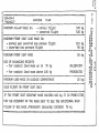
2.6. Masses.a
:z
kg
- Max.permissible empty glider
mass with standard equipment x / •••• 370
- where the mass of fuselage and
tail unit / without the moveable
1
i
balancing weig hts / is '." • • .• • •••••• 193
- Max.permissible load mass
Isee page
/
- Max. permissible load mass in
the luggage compartment
Isee page
/
- Max.per~iseible load mass on
front seatin:
- normal flight •••••••••••••••••
- inverted flight
two persons
-
XX
110
/
crew..............
95
Ma~.permissible
all-up mass in
- normal fliyht
••••••••• 9......
- inverted flight ••• ~ •••••••••••
. . . . . 1lD -
.......
-aza __ ca-=- ..... _ _ - . . . . _
570
540
- ......... __ _
xl
The standard
i.
Instrument panel lat front seat only/
equ~pment
consits of:
with airspeed indicator, alt1meter~
variometer with compensator g slip and
turn indicatoi g compass.
2. Two towing books of S2O-111 or TOST
type.
3. Two sets of four-belts pilot·s harness.
4. Two sets of seat pillows.
5. Assembling wrench
6. First aid kit.
xxi Inverted flight, the aerobatic
manoeuvres listed in item 4.5.2.
included o
CJrui<:OW PT Bidako-8iala /1..000/466/ H2
-
2-4a
50-3
-
FM3
LO~D IN LUGGAGE COMPARTMENT
---~-~-~-~---~~~~~---~~-~--
Max. load in luggage compartment is 20 kg.
The above load comprises the fixed
equipment /battery, transceiver block etc./
and a hand luggage. The mass of luggage
uniformly distributed in the compartment
does not contribute to the e.g location of
glider in flight.
The hand luggage s~ld be immobilized by
means of cord or belt using the six
removable lugs on compartment floor.
2.7. Allowed range of e.g.location lin respect
to wing root leading edge/:
- empty glider without the balancing
weights: 0.610 to 0,635
m
- glider in normal flight:
0 9 092 to 0 0 333 m
what corresponds to the range of:
23,5 to 44,0 per cent of M.SoC.
- glider in inverted flight:
0.133 to 0,333 m
what corresponds to the range of:
27,0 to 44,0 per cent of M.S.C.
- for performing the flick-roll:
0.133 to 0.204 m
what corresponds to the range of:
27.0 to 33 0 0 per,cent of M.S.C o
-NOTE;~- To define-th-e II M~aximum permissible loading mass 11
.
use the formulas given in
, item 2 . 8.
Example: The empty glider wIth standard equlpment
2
/without balancing weights/mass is: Qc =370kg.:
Both wings mass is Qs =172 kg • According to the
formula: [763+Qs-2Qcl /item 2.8/maximum
loading mass ~ 763+172-740a~kg
50-3
FM3
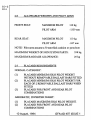
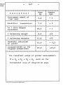
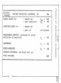
2.8
ALLOWABLE WEIGHTS AND PILOT ARMS
FRONT SEAT:
REAR SEAT:
MAXIMUM PILOT
110 kg
PILOT ARM
-1339 mm
MAXIMUM PILOT
110 kg
PILOT ARM
-247 mm
NOTE! Pilot arms assume a 70 mm thick cushion or parachute
MAXIMUM WEIGHT OF NON FLYlNG PARTS:
398 kg
MAXIMUM BAGGAGE AI.LOWANCE:
20 kg
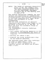
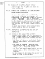
2.9
PLACARD REQUIRE:MENTS
NORMAL CATEGORY:
(1)
(2)
(3)
PLACARD ~UM SOLO PILOT WEIGHT
WITHOUT REMOVABLE BALLAST BARS FITTED.
PLACARD ~UM SOLO PILOT WEIGHT FOR
EACH OF 2 REMOVABLE BALLAST BARS WHEN
FITTED
PLACARD FOR FRONT AND REAR PILOT
COMBINATIONS
AEROBATIC, INVERTED FLIGHT:
(1)
(2)
PLACARD MAXIMUM SOLO PILOT WEIGHT.
PLACARD FOR FRONT AND REAR PILOT
COMBINATIONS
10 August, 1994
GFAAD 407 ISSUE 1
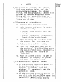
PLACARD REQUIRE~mNTS (cont)
2.9
FLICK ROLL
(1)
PLACARD FOR FRONT AND REAR PILOT
CO~lNATIONS
In this case the AFT CG LIMIT is moved forward making
it most unlikely that a rear pilot can be carried.
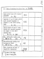
2.10
WEIGHING THE GLIDER
The glider should be weighed to scheme 3 on GF A
weighing form WI and the pilot limits computed on form
W2. Both of which should be glued into the back of the
log book.
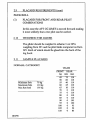
2.l1
SM1PLE PLACARDS
NORi\1AL CATEGORY
VH-###
FRONT
Minimum Solo
Maximum Solo
Max fuse load
18/5190
70 kg
110 kg
195 kg
kg
45
50
55
60
65
70
75
80
85
90
95
100
105
110
REAR
.
nun max
75
60
40
25
10
0
0
0
0
0
0
0
0
0
110
110
110
110
110
110
110
110
110
105
100
95
90
85
,1 Ul
3:0
tN.
lH
~
..o~
Ii
"Q
.j
.-,.."
oI
CI
to
j;"
.....
....
o
o
o
'.
...
.t,.
I~
r=coccc~oco=~oa~~~uc~=~=uooao~ocoronoocaocac9=a~c~cmac~~~~o~occ~~mcol
310 .3:
: Empty glider mDsn wi th standard:
L~~~:~~~~2
__ ~~2__ L_~~ __________ L_____ ~_~ __ J__ -_______ JL ___ -_______ :
I , .
I
Location or c .. g for empty gliderl
r \.J i t h 8 ton dar d e qui pm en tin
~
I• r 6 0 pac t tor 0 ate h 0 r d lOB din 9 tI
L~~~~ _________ -~e L!!!..L _____ ______
t
__
.--
I
:
I
I
0
L
Static Clement of mase of empty
d r d e qUi pm e n t
I 9 1 i d €I r wit hot anD
I
r
'2 ?
(
I
r
6 -J..;) .
_tt' __ ---- - __ ..
~_~ __ -
I
;
I
•
:
:
I
I
05
a
_____
D
l- __ ,_.~_
c.. _ _ .,. _ _ :
r
A
f
I
,
,
I
1
I
e
IN
:
:
I
I
r
2-3 t::J
/1
1
S
rI
fin rcspect to root chord
I"
I
1
1U1
o
f
1
f
Itn
, leading edge 1
'J.~
I
L___ -_ ~g _!: _ t21.P_ -_ ~ ~ __ L~ g~ L___ ... _.. _
1. ___ ~ _.. _. ____ :
L__________ J_____ . . ____
I
: Maxi63+eQ~:e2~i:lo
loadikn g mass
*/:
B:
' k
Aq
I
II
2Ir-------~----~-~-----t-~-------f----------~---------_~_---~-N--_--:
• ~lS x .. par i
i b Ie loa d in g mn
e
In
G8
8B'
: in invorted fliQht
~ Z~9._+_g§=_~~£_oe
__
"
l 4(;'8:
___ a-L_kj).L _______ L. . _____ ~ .. __ J___
I Date, _eignature
an d Bea 1 of
I
I
I
I
J
,
:
l
L__ -_o:J _____ a.~
c- _ _ _ _ _ _ ....
f
~
I
v
L:~~~~:2:~~-~~~~~~~~~~~~------~--U~~~~v:--J----------L---______
-1
21 7ty Qs- mass Of. bath wings;
;.:(Qc- mass of empty glider.
-
2-6
-
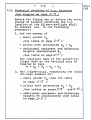
2.9. praphical checking of c.g o loc~tion
!see diagram on page 2-11 L
Before the flying day or before the every
change of loading condition the c.g.
location of the glider-in~flight shall
be checked acc. to the following
procedure:
1. Add the masses of
- empty glider mo
Isea table on page 2-5 I
- pilots with parachutes m1 + m2
- additional equipment and balancing
weights incorporated m3
Isee table on page 2-7 /
The resultant mass of the glider~in
flight mark on the vertical axis of
diagram on page
m m mo + m1 + m2 + m3
2. Add jalgebraical, respecting the sing/
the mass ~oments of:
- empty glider 1'-10 jsee the table
on page
2-5 /
- pilots with parachutes M1 + H2
/see tables on pages 2-9
and 2-10 /
- additional ~qu1pment and balancing
weights M3 incorporated Isee table
on page
2-7 /
50-3
FM3
-
50-3
FM3
-
2-7
~~===:~=====~=~========~=aq=a=c=====F====~a~===
~
E q u 1 p men t
~ Moment
Mass
I
kg
:
5,.2
I
kgm
-------------------------1---------~---------lost rument panel of
I
,_ 4
rear seat
:
-------------------------i---------r---------RS-6101-1
transceiver
7,,2
+ 2
I
I
I
I
I
I
TA - 03-A Oxygen
equipment
___ __ __
~~
~
~
~-_~~~~~~_~
+ 1
__
~~-~~_~~
I
1 balancing weight
:
__
~L~~_~
___
~
__
I
6 03
:
-11
~~~~-~-~-~-~~~~~~~--~~-~~~~~~-~-~~~~~~-~--~~
I
t
2 balancing weights
: 12,6
:
-22
--~~---~~---~--~~-~-~--~-j~-~-~~~~~~-~~--~~~~
I
i
Snow-ski installed
on glider
•
: 11,,5
I
i
-
0.3
-~~~;;~;:;~-~d-~~-;h:----1-~~-~---::--:~~-~--1
=~~:::::=:::~:::::::=~=~=j==~:~===Jg=====:====,
The resultant value of glider mass-moment:
M
= Ho
+
Ml + M2 + M3
mark on the
horizontal axis of diagram on page
uruk:OW PT Uielako-l3iala / lOOO/ 4.&6/ HZ
...
2-8
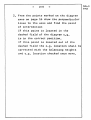
3. From the points marked on the diagram
axes on page 16 draw the perpendicular
lines to the axes and find the point
of intersection
If this pOint is located in the
dashed field of the diagram c.g.
is in the correct position.
If this point is located out of the
dashed field the e.g. location shall be
corrected with the balancing weights
and e.g. location checked once more.
50-3
FM3
. , Ul
3:0
().ll
t.H
..
o
.
I:' , - " - - c:
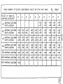
Mass moment of pilot /parachute incl./ on the front seat in respect
..
)"
to the leading edge of wing root chord.
'0
Ml
/kgmj
o-f
~ ==R=u=~u==~ua=====~==ma~==mQ9~~~=,~u=~~=~m=~=~===~=~~u~mua~=~===aapcma=m$
:; Pi 1 t
~
0
~
f
&.. 1
mass 1"1
jparsch.incl/kg
0
I
I
i i i
I 2
D 3
9
a
I
J
a
I
d
11
10
I
I
v
4
,
5
I
I
I
6
I
J
,
7
I
I
I
8
I
I
-76
I
-78
I
-91
I
,
-92
I
I
,
9
I
~~ ------------------t----i----t----t----i----~-----f-----~-----i-----~----50 wi thout pillow I
•
a
I
I
D -70 I -71 I -72 J -74 I -75
:;g:-
-;;-~
t-I
wit h pi 11 ow
I
I
I
B
G
I
I
I
I
I
-74.I -75
I
I
I
-79
------------------+----+----.----~----~----~-----~----~-----~-----~-----,
I 77 a
a- 78 1I 7 9 II -8 l 'I -82.I
60 \-v i t h ou t pl.. 11 OW.-83.I - 8
5,' -8 6 II - 8 7 II -89 D
wi th pillow
r -81 aI -82 ,'-84
I
I
I
-95
I
I
-87
I
i
-881I -90'•
-94
------------------~----~----~----~----.----~-----~----~-----1-----r----o wi thtOut pillow: -91 : -92 : -93 1-94 : -96: -97: -99:
-100 :-101 : -103 I~
7 wi th pillolltJ
1-95 1-97 '-98 I -100 8-101 D -102 B-104 Q -105 '-107 I -108 u:
------------------t----t----f----~----i----~-----f-----~-----i-----~----without pil1owl-l04D-106t-107D~1081-1108 -1111-113 1-114 '-116 • -117
80 ·
_,~
h
11
__ ~:; __ ~:_-~~___ !::~~.~:~:~~::::!:~~~.::!:~.:-::~~l:::=.-:":~~~-l:~::-L.:~~:I
I
I
I
•
t
I
I
I
I
I
•
0
I
I
I
I
I
I
I
90 wi thout pillow: -119: ,..120: -121: -123 :-124: -126: -127 : -129 : -130 : -132
------------------~----4----.----~----~----~-----~----~-----~-----~----I
I
1
I
I
I
I
I
I
I
100 without p1l1ow:-133:-134:-136:-137:-13S: -140:-141 : -142 :-144 : -145
........ -
.. -
. . .# . . . . -
.... -
..
~
........
~----
,
...
.&. ..... _ .. .L ..., .... _L ........... -G,,,,,..,..,,.., ~ ........... ~_.t --... ___l. .... -_ .. .I _ ... ___1--'''01 __
•
I
fBi
,
I
I
I
110 without pillow Il -146 1I
I
I
I
I
I
,
I
1
a•
1
I
•
I
I
z:Jrr I:fCl m= m metl; a::ar 11121 m.. alii Is mua JQ! r.. :a m= bn = ==~ t:t::I ~JiZ t!,= CJ:J I!'lJ =a:=ntD tu:a ==r1=::rm:rm:aJr::s=== :A:=====
Ia
Mass moment of pilot /parachute incl/ on the rear seat
M2
jkgm/
aaa~m.=I=mq~ama"=m=r·=a=f====r~~=uar~==uTmD=~Ta~=~~~m~~=~=====T~m=~=r~n=~.
Pi 10 t of mas s M2
/ par B C h • inc 1 /k 9
: 0
: 1
: 2
: 3
I
I
I
I
: 4
r
: 5
:
I
8
6
:
,
7
: 8
:
I
I
9
~~~~---~-~-~~~--~~r~~-~+-~-~~-~-~-~~~~~~---~~--~~~----~-~-~~~--~--~---~-
50 wi thout pillow:
with pillow
I
:
:
:
:
: -13;
I
I
8
I
,
I
I
I
I
I
I
-17
I
-181 -191 -19
I
-13:
-17'
-14: -14 ~
-18 1 -18 I
-14
-18
------------------~----+----~-----~----~----4----~----~-----~----~-----II
without pillow' -141 -141 -14 I -14' -14' -15 I -15 0 -15' -15 I -15
60
with pillow
I
I
Wl. t
. h pi 11 ow
I
wi th pillow
:
-181 -18.-18
J
-191
I
-19' -19
•
I
I
-20 aI -211I
-211I -21
I
-22
-22: -22 ~
-20
------------------t----t----t-----~----T----i----_r----i-----~-----t----~
without pillowl -151 -151 -15' -151 -15. -15 I -15' -151 -15' -15 I-"
70
• -20 I8 -20,I -20.,
-20 II -20
I
I
I
-21
0
-22
I.
------------------t----t----t-----~----i----i----~----~-----i-----~----80 without pillow, -151 -16. -16. -161 -161 -161 -161 -161 -16' -16
-21: -21: -21:
-21:
-22;
8
-22:
------------------t----t----t----~~----i----1----~----1-----i-----r----90 wi thout pillowl -16. -161 -16 V -161 -16 0 -16. ...16 I -16 I -16 I -16
------------------f----f----t-----~----i----1----~----~-----~-----~----100
wi thout pillow, -15, -151 -15 g -15 G -15 I -15' -15. -15 I -15 I -15
8
•
I
I
•••
I
I
I
------------------T----T----T-----r----'----,-----r----~-----~-----~----110 wi thout pillow 8 -15 1
I
•
•
I
I
I
I
I
I
I
•
I
I
I
a
I
••
==a~m=Q=q=~cQta=mQL===a&=maQ~~~D=ubaQ=q&a=a=d==~m~a3u=a~Q=~==~Da===~=====
"tn
3:0
(.HI
VJ
cr~------------------------------------------------------------------------------------------------------------------~
r.
~
GRAPHICAL CHECKING OF IN FLIGHT e.G.. LOCATION
Diagram valid for gliders of maximum allowable empty glider mass
/with standard equipment/ of 370 kg
~
o
~
~
~
.~
~
;;"
-0
0>
<.0
CD
<
ru
ITI!
J--l
;;-
f-J.
0.
.......
N
o
o
~
...
-h
,
C1"
0
~
0<:
N
5
f
'(}
.
"K..---.
-
II
(Q
f-J
II
,co
,
-h
~
0
:3
II
f-J.
0..
(f)
"
Q)
0
rt
•
Z
0
OJ
I
...,.
IN
co
LJ1
-
-
.I!\
-
-
2-12
50-3
FM3
EXAMPLE:
Individual data of empty glider /from table
of weighing the glider on page 2-5/ e.g. :
mo
a
372 kg
=
Mo
235
kgm
Crew:
Front seat
pilot with pillow IDl = 60 kg, M1 = -81 kgm
Rear seat
pilot without pillow m2 =96 kg: M2 B -16 kgm
Additional equipment
- Instrument panel of rear seat
5,2 kg - 4 kgm
______ Z~g_~9_!_g_~a~ __
- transce1%er
IDw
=
12,4 kg Mw
m -
2 kgm
Glider-in-fllaht mass:
!
m
= 372
Moment of
M
m
=
+ 60 + 96 + 12,4
91ider-in-fl~ght
235 - 81 - 16 - 2 =
540,4
mass:
kg
136 kgm
The perpendicular lines from points
m = 540~4 kg and M = 136 kg on diagram
of page2-11 cross in point A which is in the
dashed field o The glider-in-flight e.g.
location is correct.
. , Ul
3:0
().ll
~.
t.H
r·...
.-~~-~--
tv
~f~mm~=a===nu~~~=~=cD=~a=an=R~u~=~m====w==~~nq~==~~~c~a===~~m=aD~~
~ISZD-50-3
~
~ uPUCHACZ"
LO,.DING
•
I•
PLAN
~
o
~[~;~i~~M-;~L:~;-;;~;-I~~---:-~~;;;i-fil~h;----------------5;~-k~1
It
~
~
f-'
.. inverted flight
540 kg
I
~--~--~-~~~~~----~~~~~----~--~-------~~~~~~~-~-~~--~-~--~~-~~~~~
~ MAXIMUM FRONT SEAT LOAD t1ASS IN:
~
- normal and inverted one person flight
~
- inverted two persons flight
ND _ _ -
___________ -
______________ -
___________ -
:
110 kg :
95 kg 8
_____________________
MINIMUM FRONT SEAT MASS
,
55 kg :
USE OF BALANCING WEIGHTS
- for cockpit load mass UP to
~
I
70 kg
OBLIGATORV
:
I
- for cockpit load mass above 100 kg
PROHIBITED :
-------------------------------------.---------------~----------~
MAXIMUN
LOAD MASS IN LUGGAGE COMPARTMENT
20 I<g :
-----------------------------------------------------------~---~
SOLO
FLIGHT ON FRONT SEAT ONLY
;
---------------------------------------------------------------;
IF THE FRONT SEAT OCCUPANT MASS EXCEEDS 100 kg IT IS PROHIBITED:
Fn~
THE OCCUPANT OF THE REAR SEAT TO USE THE ADDITIONAL BACK
PILLOW IF HIS MASS /PARACHUTE INCLUDED/ EXCEEDS
75 kg
:
I
:
=D~~A~~.a~~=~==Q"a?ac~Qm=am~==~=~~=~~c=DDc~a=mga====m"am=a~~~aa~
-u
rio
Q)
00)
D> .,
~Ig-
!)
(.Om
J
:J
'"'010.
I\)
...,.
•
vJ
I
Q.~DC~UQ
• • "qQ.cmnm~naUpmg~D~nDnAa~nOCP~QDammQ"Qa~=DDauamD~~nQ~C'
_~~~~E~:
___ ~:~~~_~:~~:~::~~:_~~~~:~~~__ :~~___________k!:___ ~
NORMAL FLIGHT IN:
INVERTED FLIGHT INI
- smooth air
- gust conditions
V
Q
Va
g
- smooth air
- gust air
97
not allowed
MANOEUVRING AIRSPEED /airspead for abrupt
deflection of controls/:
NE
116
86
"'0
t-'
CD
o
,a.
ClJ
o
-n
"(]
,o
CD
CD
CD
VA
a
fo-l.
81
V
WINCH-LAUNCHING
AIRBRAKE EXTENDING
brake extended
T
Vw
ItI
t2
81
59
and flight with air
J-I
.,UJ
I
'"0
a
a.
I
I
e
~w=Dam.am~~q • • wa~~au~a=mmau~~mDQ~~=~mumcau~m~a~g~um=am~OQmoaga~.d
..........
,~
--~--------~--------------------------------~
....
~
Ol
,....
•1
i•
116
N
CTI
Cl)
AEROTOWING
I
fooJo
•
co
CD
OJ
••
-ntn
2:0
VJI
VI
-
50-3
FM3
-
2-15
Placard of restrictions
RESTRICTIONS
-~--~---~---~~--~-~~-~--~-----~~-~--~----~-~-~
-
GLIDER NOT APPROVED FOR NIGHT-FLYING.
-
WINCH TAKE-OFFS ALLONED WHEN USED THE
-
BOTTOM HOOK ONLY.
FLYING UNDER ICING CONDITIONS NOT
RECOMMENDED.
-
INVERTED FLIGHT. ROLL AND ASSOCIATED
AEROBATIC MANOEUVRES - allowed in smooth
air only and with floor-belt fastened.
FLICK RODL - only with two occupants
PERFORMING OF THESE MANOEUVRES BY THE REAR
OCCUPANT allowed only when the rear instrument panel is installed
[QJ
..
-- ...---. ---. -
Trimming tab slider - placard on the LQHo board. at front
and rear seat
'_ .. _--_ ..
__._-_
..
Air brake slider
- placard on the L.Ho board at front
and rear seat
Oruk:QW PT Biehko-13iala / l.OOO/4.66/1Jz'
-
2-16
-
lock
- placard on the canopy frame at front and
Canopy emergency
jettison~ng
rear seat
Air-conditioning tab slider
- placard on the instrument panel at
front seat
.. - .. --------"
t\t
~~
" ci~tJoooo~V
-. ___._____ . _..J
Pedal adjustment
- placard at front seat floor
before the control column
50-3
FM3
-
50-3
FM3
2-17
-
'liheel brake
- placard on the L.H. board at front and
rear seat
---
.-.
-- -----------
Towing cable release
- placard on the L.Ho board at front and
rea r seat.
3.
PE.~FORMANCES
. . . . _ . . . . . . . .u.
CD . . . . .
-
3-1
50-3
FM3
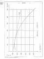
/Fig .. 4/
~
Calculated speed polar plotted on Fig. 4
follo~ing
has the
main points:
- min. sinking speed 138
ftjmin at
about
40 kts
-
QaX.
lift /drag ratio 30:1 at about
46 kts
Other points of the polar:
--~~~----4r~--lr-~~~~~~~~~~~---r-~~-~~~-~~~
V
kts
:
J
43
:t
S4
:
1
65
: 75,5 :
I
1
86
:
1
97
~-~~----~~~~~~---~~--~~~-~~~~-~~~~---~-~
I
1
,
r
1
f
W
ft/min : 142 : 187
~
262 ; 378 : 537 : 738
I
I
I
,
•
I
-~~--~~~~~-~-~~~~~~~~~~~~-~~-~~-~~---~-~
I
whore:
V
- airspeed
W - sinking speed
I
1
-
50-3
FM3
4.
GLIDER
-
4-1
OPERATION
~---~~-~~~~-~~~-~
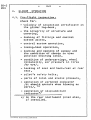
4.1. Pre .... f light inspec,tion
!,
Check for:
- validity of inspection certificate in
the glider log-book.
- the integrity of structure and
covering,
- locking of fittings and control
system joints p
- control system operation_
- towing-hook operation,
- locking and opening of canopy and
the condition of canopy in open
position securing cable.
- condition of undercarriage. wheel
rollabilitYQ air pressure in tires
/by eye/,
- locking of seat and back-rest at rear
seat
-
0
pilot~s
safety belts,
- ports of total and static pressures
- operation of airspeed indicator
lit should operata when blowing on
ports/, xI
- operation qf slip-and-turn
ind1cator x /
xl In
the rear instrument panel a150*
if installed.
On:i<.:OW PT Dielsko-Biala / l.000/ -l.b6/ Hl.
4.2.
~ockeits
4-2
-
and their arrangements
The standard equipment comprises one
instrument panel at front seat only.
The instruments are located in such a
way that they are satisfactorily visible
f.orn the rear seat also.
During the flight the upper panel edge
allows for controlling the glider in
respect to horizon, or in respect to
towing aeroplane.
Additionaly the glider can be equipped
with the second instrument panel mounted
on the canopy.
The cockpit is de~igned to use backtype parachutes or pillows of 12 em
thickness when pressed. The front seat
allows for the pilot above 2 m tall.
The pedals are adjustable in flight
/5 positions/; adjustment of pedals is
made by feet when the knob on the floor
/painted brown/ is pulled o The pilots
havi"g short legs or small mass should
use toe additional cushion on the backrest.
The rear seat allows for the pilot above
2 m tall. The seat pan is adjusted on
the ground /vertically and longitudinally/ by shifting the backrest cross tube
/4 positions/. When the position is
adjusted the cross tube should be
secured with the lock.
In general the higher pilot~s position
in the rear seat, the better is the
Visibility forward including the
instrument panel at the front seat.
Pilots having the short legs should use
the additional back rest pillow.
The standard equipment comprises four
belt pilot's harness at both seats.
The installation of the floor-belt
/additional equipment/ is possible.
50-3
FM3
-
50-3
FM3
4-3
-
Fastening of the floor-belt is obligatory
for flight in which the inverted flying
and associated aerobacy manoeuvres
/controlled roll. controlled half-rollhalf-loop, controlled half-loop-halfroll/ are intended. In other flights
when the floor-belt is out of operation
it should be placed below the seat p111o~
and immobilized by means of the button.
The cockpit is closed with the integral
perspex canopy fixed on two hinges on
the R.H. board with the possibility of
emergency jettisoning.
The opened canopy is hold up with a cable
which when closing the canopy pulls up
automatically into the winding set
behind the front seat back rest.
Both seats have the control columns
coupled each other. the pedals and other
control levers are marked with placards.
Operation of controls is of conventional
type.
The handles are arranged as follows:
=~====a=uc=Q====~====f=======~=u==f=mc====~====
ca ......
Control
system
_e.-.
.
c::a _ _ . . . .
• Position of IColour of
i - .....
handle
: handle
_s:a_ .... -... .,-i-..
- - .. - - ........
__ .. _ ...
Air brake slider
Wheel brake knob
Trimming tab
slider
:00
a
I
on the left
blue
black
I
I
I
on the left
green
•I
Towing cable
!
release handle
Canopy locking
I
the left
: on the left
:on the left
Canopy emergency
jettison handle
:on the right
:
red
I
J
uru;'.:OW PT I!ielako-Uiala / lOCO/ 406/ 'tlZ
yellow
I
lever
c._ em . . . . . . . . . tID . . . . . . _caco _ _ . . . . c=-=-cwc.a
_-..ee ......
~-~
•
ett . . . . . . . . _ _ or.1IICD _ _ _ _ _ ca:a
red
/sealed
with lead/
--.::=aw _ _ _ ....... _ - - _
-
4-4
-
50-3
FM3
The cockpit is air conditioned with the
side windows in the canopy. seperate for
the front and rear seat.
The front seat has adjusted inflation
on the perspex front part above the
instrument panel operated by the slider
in the panel/black ball-knob/.
80th seat have side pockets accessible
in the flight.
Two nests for balancing weights are
located before the front seat.
The weights of mass 6,3 kg each are
not interchangeable. They are fixed on
bolts with tommy-bars without using of
tools.
In the cockpit and the luggage compartment the fittings for the oxygen
equipment and transceiver are installed.
4.3. .Service before take-off
4.3.1. I.r~n~!?.r!a!i£n_0!l !.h~ !!ir.fie!.d
-
During the transportation of the glider
the cockpit should be locked and the
windows opened~ The air brakes can be
extended or retracted.
The glider /
with or
wi~hout
the
occupants/ can be towed by the front
hook or by the tall lug having the
posibility of free turns. The
towing cable length should be
The glider can be also rolled
fon~ard or backward. At turns
should be pressed or the nose
ground
at least 4m
on wheels
the tail
lifted o
50-3
FM3
-
4-5
-
4.3.2. 6diu~t!na ~f_the_r~aL ~e~t_h~i~h~
The rear seat can be adjusted in an
unloaded condition as follows:
1. Open the canopy and the secur1ng.tab
on the L.H. fuselage surface under
the wing /accessible from inside/.
2. Shift the supporting tube to the left
up to release the seat pan.
3. Set the seat in the required position,
put on the supporting tube and close
the securing tab.
4.3.3. Lockina of hooks
_____
....
fI/IJ-
___
.-_
In the Qliders having TOST hooks they
are operated from cockpit by pulling
the releasing knob. when the knob is
free the hooks close automatically.
In the gliders having SZO-1I1 hooks
each one hook opens independently
when the near hook positioned tensioncable i6 pulled.
It is necessary to use the extending end.
The main wheel valve is located on the
R.H. side and i6 accessible after shield
deflection. Pressure 3.0 at.
The front wheel valve is located on the
L.H. side.
Pressure! 1.2 at ..
Uruk:OW PT l3ic:hko-8iala /2000/466/ 'd2
4.3.5.
-
4-6
~r~i~aae_oi ~u£t~
- Remove the pressure ducts of the rear
seat instrument panel /3a and 3b F1g.2,
and plug them on the port end.
- Detach the drainage units from the
ducts of the frent seat instrument
panel/in pOints marked with arrows
in Fig. 2/ and blow through the
drainage units together with port
ducts,
- screw out the drainage unit bowls,
take out and dry the inserts.
Install the dried elements and bowls
~/tighten firmlY/a
- connect the drainage units free ducts
to the rear seat instrument panel,
- check the operation of airspeed
indicator lit should operate when
blowing on ports/.
4.3.6. 6s~e~b!i~g_of ~a!a~c!na ~e!g~t~
Put the weight into proper nest and
screw on full the clamping screw.
-------
4.3.7. Procedures ................
before take-off
.....
1. Balance the glider with balancing
weights according to the crew mass and
if necessary put on the back cushion
IsmaIl or light weight pilot/.
2. Adjust the rear seat correctly.
Before the solo flight clamp the free
belts and protect lor removel the
contents of side pockets in the rear
cockpit.
-,...-~
50-3
FM3
-
50-3
FM3
4-7
-
3. Take place in the cockpit g adjust the
pedals and fasten the baIts.
4. Check full movements of controls,
air brake and trim~ing tab.
Retract the air brake. Set the triQ~ing
tab slider according to the take-off
~ethod and crew mass.
5. Check the operation of turn indicator.
6. Close the canop~.
7~ Insert the cable into the hook and
check the locking pulling i t firmly_
4.3.8. Eo~t~f!i~h! £r~c~d~r~s
-
S~itch
off the turn indicator. If
necessary remove the used batteries.
- If necessary drain the instru~ent
installation according to 4.3.5.
- Inspect the glirler as before taka-off
and remove the eventual failures.
4.4. Controlling
4.4.1. £e~e~a! £h~r~c~eLi~t!qLoi £Q~tLo!l~n~
The SZO-SD-3 "PUCHACZ" glider allorlS
for correct and easy controlling 8S
do it ~ost of the ~odern performance
sailplanes.
Cha ract eristic8 :
- short and well shock-absorbed
9 round run,
- good lateral and diractional
controllability,
- safe lo~ speed behaviours with-out
the Gxces9iv6 inc linat10n
~o
-
4-8
-
50-3
FM3
spinning o
4.4.2. Io~e=-of.f_a!!.d_f!iah!. !n_a~r2.t£.w.!.n9.
/front hook/
Pay attention to have the towing cable
straight-tensioned before take-off.
According to the crew mass adjust the
balancing tab:
- solo flight - -nose heavyM
- heavy crew neut reI"
The ground run begins on two wheels.
f.
At the airspeed of about 16-22 kts .
the front wheel should be lifted by
pulling slightly the stick
,when
avoiding to hit the ground with the
tail skid. According to the all-up mass
the glider airborns at speed of 35 to
41 kts • When the flight becomes stable
correct the setting of trimming tab.
Recommended towing airspeeds:
- at climb 51 to 65 kts
- at cross-country flight 65 to
81 kts.
4.4.3.
!!.i!!.cb..-!a~n£h!n9.
J!?.o.!. t 9..m_h~.o.!U
Before take-off the glider should be
positioned in line with towing cable.
The slight directi~nal deviation is
allo~ed
to the l~ft of e cable but,
the deviation to ~he right should b~
avoided in respect to the possibility
front Wheel to the cable contact
during the ground run /the possible
touching or even the rolling of the
front wheel through the tensioned
cable does not creat~~ however, any
danger, nor disturbs the ground run/.
of
-
50-3
FM3
4-9
-
The adjusting of the trim~ing tab
according to the pilot's ~ass on the
front seat.
- solo light weight pilot - Moose
heavy~
- mean pilot -
-nose heavy"
- heavy cren - "neutral"
The adjustment of the tab should not
be corrected during take-off
The glider ground run j1nirially on
~heels
is correct~
on the cre~
conditions~
two
next on the main ~eel/
and the run length depends
sass and take-off
After airborning fly
correctly near ground avoiding the tail
skid to ground contact and pass into
steep climbing.
With glider correctly balanced the
stick forces are not large, and with
incorrect balance the forces are not
excessive.
The launching speed should be 49 - 54
kts Inot less than 43 kts /.
In the final climb phase slightly pull
the stick.
Before releasing the cable put the
stick forwards to discharge, th& cable.
During intended self-releasJnQ the
stick should be pulled forwanrafter
the releasing.
After releasing the cable, pull the
releasing handle once more and pass
into the nor~al glide.
Depending on the glider all-up mass
and the winch power with a cable .550 rn
long in smooth air the gained height
reaches .200 - 250 m.
(n..Jo:O"-PT Bi"lako-ei&1,"/!COC/~ui../l1l
-
4-10
-
4.4.4. Long1tuQ1nal trim in free flight
The
trim~in9
tab
allo~s
for glider
t ritri :
-
for solo light weight pilot - within
the airspeed range of 32 to 81 kts.
- for heavy crew - within the airspeed
range of about 42 to about 116 kts.
4.4.5.
~t~l!i~
/airspeeds lAS/
Depending on the glider all-up ~ass
the stalling speed in the straight
flight is of about 31 kts for solo
light~e1ght pilot to about 38,8 kts
~eavy c,e~ and all-up ~ass of about
570 kq /.
The stall warning is in from of perceptible vibrations of fuselage p
oscillations of airspeed end "over
horizon- attitude. When stalled the
glider drops down ~ym~etrically in
general and fat further pulling the
stick/ with tendency to drop the wing.
The stall in turn is preceded by
distinct inclination to decrease the
turn radius. With further pulling the
stick glider drops with tendency to
increase the bank.
Ifp ho~ever, the tendency to
decrease the turn radius is prevented
with proper aileron counter action,
the stalled and strongly vibrating
glider turns without dropping.
With air brakes extended the stalling
speed in straight flight is of about
35 to about 41 kts
depending on a11up sass.
In all the cases of stalling the glider
allows for recovering the normal flight
reliably by the resolute elevator
50-3
FM3
-
50-3
FM3
4-11
-
deflection and if necessary by the
other control deflection for balancing
the bank.
4.4.6. £iLc!i~_
When circling in ther~als the glider
has very good lateral. controllability
The circling speed is of 38 to 49 kts
depending on all-up mass. bank and
flight conditions.
Before the intended spinning in one
person flight the pilot of mass beloN
1651bs should check the proper glider
balancing ~ith weights.
When entering the spinning in the
straight flight it is recommended,
for makin~ it easy, to have a little
bank tow8Ids the intended spinning
direction. It is also possible to
enter the spinning in the turn.
In both the cases it is recom~endad to
decrease the airspeed by slow pulling
the stick and in the so~ent of stall
initiation to pull the stick full.
Deflect the rudder towards the intended
spinning. The reco~mended aileron
deflections are listed in table on
page 4-13. To obtain the stable spinnin
especially in the case of heavy cre~
the precise full deflection of elevator
is necessary /~ith the comparatively
high force depending on the crew mass/.
when the above directions are observed
the glider perforQs the steady spinning
with the characteristics described in
the table on paga~-13
1
_
NOTE:
4-12
-
The table of spinning characteristics is not the loading plan.
The table concerns glider with
all tha additional equ1p~ent
variants acc to the loading plan
on page
2-13
The aileron deflection towards the spin
favours the appearance or augmentation
of-longitudinal oscillations /especially
in the solo spinning with light weight
pilot! and therefore it is not
recommended.
The not full deflection of elevator
/specially wi th heavy crerl/ leads to the
airspeed increasing up to 54 kts
or
more and even the automatic break of
the spinning.
The reco~mended recovery technique
consists of:
- full rudder deflection opposite to the
rotation~ a considerable leg force is
required
- waiting for about 1 sec.
- pushing the stick forward more than
to its neutral position.
The maksimu~ delay when this technique
is used is lower then 1 turn.
In case of other technique or not
resolute action the d@lay can be more
than 1 turn.
l_
50-3
FM3
-ntn
2:0
VJI
VI
.,
c-~--------------------------------------------------------------------------------------~
~.
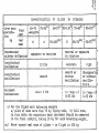
CHARACTERISTICS
o...
OF
IN
GLIDER
SPINNING
3.=a~aa~a=ua==mDQ2==f===~=2==,=====u,r~~macQ=="===~=~~~=a=ac=~,~="c==ma~'d=
x
x 190-110 a 75-90 : 90-110
w- Crew mass
f
t
I
55-75 175-90 J
55-75
l
-
~
9
PI
g
~
~
N
ron
I
.
rear:
0
h
I
J
u-!2~! ___ l~~~~~-~~4-------J---------~-------~--------~- _________ _
k '
xx /
xX
!.~::ac
~
h
~
sea t
_____ _____
~
~_~~
__ IL __
:
0
I
~~_~~_J~~~
:55_100
___ a ___
~L
~~
8
Recommended
I
aileron deflection:
__
I
8
J
I
155_7S / II 55~75XX /
I __
__ a ________ _
~~J_~~_~~~J~
I
opposite to rotation
0
I
:
~~
~JL
I
neutral or opposite
to rotation
~-~~--~-------~--~~r~~~~~--~~-~~~~--~~~-~~~-~~~~~--~-~ -~~~~~~~~~~--~~~~-
Long! tudinal
I
longitudinal
oscillations
I
•
D
~~
:
~!25!!Q!!!2~ _______ ~ __ -______ ~~~~~~ ___________ ~ ___ ~~~~~~~~___ : ____ ~~~~___ ~
I
a
I
I
smooth
:
hid
("..
smoot or
I
ise~peari 9
without
: or w1thout
oscillation I oscilla-
:
I
I
•
I
r
in range of : in range of
I
I
0.-32 kts
t
ions
~-------~-----~---~r--~-~~-~~-~~~-~~~~~--~~--~~-~~~~----~~~--~----~~~-~--.
8
J
I
Airspeed
indications
:
aI
about 0 kts
~cu~mu=~=a=a==.=.Da~~
xl
xxI
I
I
0-43 kts
~~~~~~.u==u.~=ma==.~=xa_~.~CR~=~
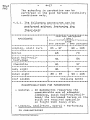
For the flight with balancing weights
al pilot of mass more than 75 kg flying solo, bl full crew.
In this table the equivalent mass increment should be observed
in the front cockpit, taking 10 kg for each balancing weight.
Never exceed real mass of glider - in flight is 570 kg
II
-
4-14
-
- can be performed in 2 ways:
af
With simultaneous, gradual deflec-
tion of ailerons and rudder at the
airspeed of about 38 - 43 kts ,
the directional sideslip with bank
of to 10 - 15
is obtained.
Indications of airspeed indicator
drop below
27 kts •
Keeping up the rudder deflection
I
requires the applying of resolute
force on pedal; releasing of this
force causes the automatic neutralizing of rudder and the glider passes
into a turn towards the bank.
With the bank of above 15 the
glider also turns towards the bank.
b/ With deflection of controls in an
order: at first the ailerons, Shen
rudder q when the bank of ~ 15 is
obtained~ the glider allows to enter
into directional sideslip with bank
of up to about 30°. During deflectio
of rudder the force on pedal disappears simultaneously it appears the
impulse to raise the glider nose
above the hOiizon.
It is necessary, in this moment, to
stabilize the glider by pulling back
the stick. Indications of the
airspeed indicator in this condition
drop down to about o.
When recovering with aileron and
rudder deflections simultaneously
lit is necessary the resolute
deflection of rudder towards the
bank/
the glider passes into
the turn.
When recovering with aileron at
first as the bank diminishes the
rudder is neutralized automatically
and the glider passes gradually to
50-3
FM3
-
50-3
FM3
-
4-15
the straight flight; eucn a recovery
is a little
one.
slo~er
than the previous
4.4.9. -----Air
brake
.....
The air brake is very efficient and can
be. if neceBsary~ extended in full
range of per~issible airspeeds.
The effectivnsas of brakes allows to
avoid the use of sideslips during normal
approach to landing.
4.4.10
0
~~d!nR·
Generally the landing should be performed against the wind. If necessary the
landing wi th the side wind up to 10 kts
or the back wind up to 6 ~B is allowed
when paying special attention.
The recommended
appro~ch
- in smooth air 49 on all-up Qass,
54 kts
- in turbulent air 54 depending on all-up
speeds:
depending
60 kts
~ass.
The flying-path inclination should be
adjusted by the air brake.
According to all-up mass and air brake
travel the touch-down with the ~ain
wheel follows at airspeed of about
35 to 41 kts •
It is reco~~ended to touch-down with
the partly extended air brake.
After touch-down the glider rolls at
first on the main shock-absorbed wheel.
Then smoothly drops the front wheel
this affect can be delayed Ito disnish
the shock during rolling/ with gradual
pulling of stick.
-
4-16
-
50-3
FM3
The lenght of landing run in windless
condition is:
- without use of wheel brake - about
90 - 110 m depending on all-up mass.
- with use of wheel brake - about 60
80 m depending on all-up mass.
4.5.
~
Aerobatics
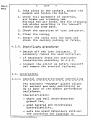
Before take-off for aerobatics it's
necessary to:
- check the correct glider balance with
balancing weights /concerns solo
flight/
- remove the free elements out of the
cockpit
-
p
~heck
the lockina of back rest tube
at the rear seate
- check the full deflections of controls
having the belts fastened,
oJ
- before the solo flight re~ova the
needless pillows and fasten the
pilot's harness at the rear seat.
In the flight just before performing
the ~anoeuvres it's nocessary to:
~ fasten the back belts,
- balance the glider with trim=ing~tab
on the airspeed of 60 - 65 kts
i ... a
si~11ar as for toned flight,
- check the locking of canopy and air
brake,
- shut the
tab.
~indow
and air-conditioning
-
50-3
FM3
-
4-17
Tho schoaLng in aerobatics can be
performed in the good horizon Visibility
conditions only.
4.5.1. Ih~ fo~lo~~n~ ~8~o~u~r~s_c~n_b~
£e~f~r~ei ~i~h~u~ ia~t~n!ng ~h~
floor-belt
----..-=~~~c~~~za=~c~=~c===2=r~~==Init~aI~arrspeed~~D
: __ ~_- ____ ,_~!~L- ______ _
s
crew
MP~OEUVRE
lone person
l
tV'tO
person
~---------------------~-----------i-----------Looping
stall turn
I
86 - 97
I
90 - 105
i
----------------------~-----------~----------~
65
~
70
Spiral
~-~-~---~~---~~~~~~-~~~~~---~~~---~~-~-~~~~~
I
I
Quick hal f-rollt
S1
I
54
half-loop
!
1
-~=~------------~-----t~----------i---------Chandelle
:
81
:
97
~~-~-~~~~~-~-~~~--~-T~~-~-~-~-9--~---~--~-
Lazy eigh t
...
o.~
~
Cuban eight
t
Laaf slides
~
~
81
:
. . . . . . . . . . _ _ _ _ _ _ . . . . . . . o:a ... ..., _______ . .
~
....... _
... _ _ -.0_.:. .......
97
~
"'f~
... - . . - . .
_~_
1
90 - .lOS
~~--~~------~-~~~-~~--~-----~---~~~--~-~~-~--
86 - 97
I
stalling speed
G;~a~~s=uAaQ=~=~~mag~=bz=~=~~~~=c==~~=~=~~~=a=
RECOMMENDATIONS FOR MANOEUVRES
- General - In manoeuvres requiring the
considarable use of elevator
/looping D quick half-rool-halfloop/ the increased forces on th
stick are required specially
in flighL with heavy cr~.
~
Looping, stall-turn, spiral is coraventional
Perfor~ing
l,____~____~____----------~--------------------
-
4-18
-
Quick half-roll-half-loop - At the initial
airspeed of 51/54 kts the autorotat1onal
half-turn is obtained when the stick is
resolutely pulled full with si~ultaneous
full deflection of rudder_
The further rotation is braked by
~eans
of neutralization of controls. Recovery
is performed by means of
se~i-loop
down17ards.
Chandelle
- At the initial air speed of
81/97 kts. the glider should
be entered into the sharp
cliobed turn with 45° bank with
such an attention that when
recovered for the returned
direction /180 0 / the airspeed
ranaed 38-43 kts •
-'
La~y
eight - At the initial airspeed of
81/97 kts the glider should
be centared into the sharp
cliobed turn ~ith 45° bank with
such an attention that when the
direction changed by 180 0 the
turning airspeed was about
43 "ktS.
After the next 45° the glider
should be recovered out of the
turn the airspeed of 75;5/81 kts
gained once-more and the same
~anoeuvre performed into the
reversal direction, then
recovered into the original
direction.
50-3
FM3
50-3
FM3
Cuban eight
-
Leaf-slides -
4-19
At the airspeed of
85 - 97/ 90105 kts the looping should be
initiated. In the upper
/inverted/ attitude, when the
inverted horizon is seen, pull
the stick full and deflect the
rudder full.
The glider continues the loop
and passes into 3/4 attitude
making the quick autorotational
vertical turn /towards the
deflected ruddert. When the
turn reached 180 the stick
should be resolutely pushed and
the rudder neutralized to brake
the further turn and to retain
the glider in diving in
direction reversal in respect
to original one.
When the airspeed reached
90 kts
perfor~ the second
looping and recover into the
normal flight.
/dallying with stall/. Enter
the stalling on the same ~ay as
for the spinning and immediately break the turn using the
opposite rudder deflection and
short pulling the stick.
Then pull the stick once-more
and deflect therudder till to
the stalling into the opposite
direction etc.
manoeuvres can
-
50-3
4-20
FM3
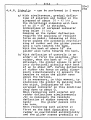
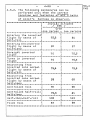
4.5.2. The following
be
performed only when the correct
of all
location and fastening
of pilotgs
5 belts
harness i8 observed.
~~~=~=c====c==z~=g=ca:m==~=r~r-~~~=====~e3====~
:I ______ L__BL
~n~~
•
.,,one
_________ _
a1rspeeu
~t§_L
Crew
person I two persons
-~----------~~------~~--~~--~~--~~---~~~~-~~--
~
Entering the inverted;
flight by means of
half-roll
75,5
I
81
I
;
:
Entering the inverted:
flight by means of
I
:
~--~~~~---~-~~~~--~-~T~~~-~-~---~T---~~~-~----
______
____
half-loop
~
~~
~i~a~~ht
~_~
_____
I
i~~
gO
__
t
•
~~~_~_~~_~
97
___
~_~_~_~
!
70!
75,5
~i~~~:~~-~~:~;;~d----t-----;~----t------;;~;--j
inverted
-~-S_----------------t-----------t---------~-f
i
Recovering from
inve rt ed into no rtilal ~
f light by means o f :
half-roll
I
75 5 :
7S 5
':
I
,
-~~~~--~----~-~~--~~~---~~~--~~-r~~~-~~---~~~
Recovering from
:
inverted into normal I
flight by means of
~
~~!1:!2~E
I
t
59
1
3
J
65
____________ l ___________ l-___________ .
~~~~~:::~-~~::------+-----~~----~------:~----I
ro lled hal
75 5
81
C~nt
f-roll-I
I
~~!f:~2~E ______ ------+-------:---f-----------Half-loop-half-roll
I
I
108
I
,
113
~-~-~-~~~--~~---~~~-7-~-~-~~~-~-r~----~-~~~
Flick roll
fI
57
'
I
59
g=u=:~=~=;a=cc=====:cbc====~==~=ab=c=a===;;~=~S
-
50-3
FM3
4-21
-
To perform the above Qsnoeuvres by the
rear occupant of tvro persons
cre~
the
installation of rear instrument penel
is obligatory.
RECOMMENDATIONS
-
FOR
MANOEUVRES
Enterinq the inverted flight by means
of half-roll.
At the initial airspeed of 75,5/ 81 kts
the glider should be slightly pulled
above the horizon and s1multaneousely
the rotation initiated using the full
aileron deflection. Before passing the
90 0 position the glider should be hold
above the horizon by meSBS of deflection
the rudder in direction opposite to
bank fusing the "upper 1eg
4O
/.
Then gradually release the elevator
/the full deflection, if oecessaryj
and neutralize the rudder.
In the 180° position break the rotation
of the glider /neutralize the aileron/
and recover the airspeed to
65 kts
retaining the "above horizQn- attitude.
Correct the eventual bank
-
Entering the inverted flight by means
of half-loop
At the initial airspeed 90/ 97 kts
perform the first half-loop.
In the inverted position prior to the
nose drop below the horizon pull the
stick resolutely and set the inverted
flight airspeed into 65 kts
in
-above horizon
position.
In case the airspeed increases
N
unintended, open the a1rbrake in
advance.
...
4-22
50-3
...
FM3
In respect to a lo~ tollerance of engle
in the moment of breaking the loop and
the low margin of permissible airspeed
in inverted flight this manoeuvre can be
learnd when the inverted flight is
co~pletely familiar to the pilot.
- Straight inverted flight.
The glider should be retained in "above
horizon" a~i1tud8 ~ith the airspeed of
65 70 kts . When correcting the
banks pay attantion that the stick side
moveQent e.g to right results the RIGHT
wing to be elevated above the horizon
and
vice versa.
In the prolonged inverted flight the
trim~ing, if necessary, should be set
into Hnose heavy~ position~ using even
the full range of trimming.
In the straight flight the stalling at
about 59 kts. airspeed is possible.
It requires the full stick movement
forwards. When the glider drops down
the stick should be slighty pulled for
a moment then once more pushed to get
the "above horizon attitude.
M
- Turns in inverted flight
The bank of glider, when introduced
into the turn, is obtained by means of
side deflection of the stick in the
direction opposite to the intended turn
direction.
It is recomQsnded to control the olirler
with the small deflections of aileron
and rudder.
The airspeed in turn is 7~5 kts ~
~
50-3
FM3
4-23
-
- Recoverinq from inverted into nor~al
flight by means of half-roll.
Inerease the airspeed in inverted
flight up to 75,S kts • Then push the
stick to obtain the above horizon
position and move the stick to aileron
direction /full aileron deflection/.
When passing the 270 0 position retain
the glider above the horizon by means
of smooth deflection of rudder lin
accord to aileron deflection/ and
neutralize the elevator.
In nor~al position neutralize the
aileron end ruddor and return to the
steady flight.
- Recovering from inverted into
¢
nor~al
flight by means of half-loop.
In the inverted flight with the airspeed
below 59- 65 kts gently pull the stic~
In the diving th~ airspeed should be
controlled and the glider recovered
into the norroal flight on the arc-path
of semi-loop.
In case the airspeed increases
conSiderably, the air brake should be
extended in advance.
- Controlled roll In the normal flight
at the airspeed of 97 kts the glider
should be elevated slightly above the
horizon. In the same time the rotation
should be initiated by meane of aileron
deflection. Before passing the gOO
position the glider should be retained
above the horizon using the sgooth
rudder deflection in the direction
opposite to bank luse of "upper leg"/ •
• 'r ..... :01lt PT Bidol<o-Bala /lOOO/"'/:,6/11!.
...
4-24
...
Then gradually release the stick and
neutralize the rudder.
When the 1800 position passed, gradually
deflect the rudder in accord to the
~~;~r~~~9ing
the 270 0 position ratain
the glider on horizon using the rudder
deflection in accord to the aileron.
In the normal position neutra11ze the
aileron and rudder and return to the
steady flight.
NOTE: HDving some experience the rolls
can be performed ~ith the initial
airspeed of 85 kts
- Controlled half-roll-half-loop.
,
Perform the first half of controlled
roll with initial airspeed of 75,5/ 81
kts • In the inverted position decrease
the airspeed up to 59 kts •
Then pull the stick passing into the
half-loop.
Pay attention that the airspeed must
not exceed 116 kts. - if necessary
extend the air brake in advance.
Recover th~ glider from diving into the
normal flight.
c
Half-loop-half-rol~
At
the initial airspeed of 108 kts
the first half of looping in
such a way that the airspeed in the
inverted position would not drop belo~
perfor~
59
~ts
.
In the inverted position push the stick
forwards resolutely and then perform
the second half of controlled roll
/deflect the airleron, retain the
glider above the horizon by seans of
rudder deflections in accord to the
aileron/.
50-3
FM3
50-3
FM3
-
4-25
When entering the normal position
neutralize the aileron and rudder and
return to the steady flight.
- Flick roll
In respect to the troubles in correct
controlling of the flick roll at the
rear location of glider e.g. this
manoeuvre should be limited to two
persons crew only. Performing of flick
roll depends on the extorting of
8utorotation by ~eans of simultaneous
full stick pulling and full rudder
deflection towards the intended rotatio
direction. During the autorotation the
airspeed decreases considerably_
Therefore to avoid the stalling and
unpleasant dropping of the glider at
the end of the ~anoeuvra i t is
racocmended to initiate the flick roll
~ith the position pitched clearly
below the horizon.
In the steep diving accelerate the
glider to 57- 59 kts
/not more J /
then simultaneousely pull the stick ful
and deflect full the rudder.
The glider performs the auto rotation
in re6pect to longitudinal axis ftith
the tendency to climbing. Before gainin
the 3600 position neutralize the
controls to break the rotation.
If necessary finish the rotation with
the aileron and return to the norcal
flight.
-
-
4-26
In respect to the fact that the steady
inverted spinning is not possible to
be performed in the greater part of
c.g. location range this manoeuvre is
not allowed.
In the case of unintended developing
of inverted spinning as a consequence
of inverted stalling the stick should
be
pulled immediately and the other
controls neutralized. The glider breaks
the rotation nearly im~ediately and
passes into diving.
It should be recovered slowly
controlling the airspeed.
If necessary, extend the airbrakes
in advance.
The recovering from inverted spinning
into the inverted flight is prohibitedl
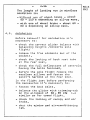
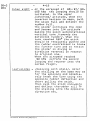
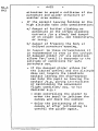
4.6. Danger and ecergency conditions
procedures
4.6.1. ~r~a~ ~r_u~i~t~n~e£ ~ele~s!nR £f_tow£a~l~ ~t_low_h~i~h~
1. Release the hook l i f the cable remained
with glider/.
2. Bring the glider to correct glide.
3.
Land in place choosen with respect to
the wind direction and other landing
conditions.
4.6.2.
tl~g~t_w~th
in£o~r~c!
aj In case of lack of
!r!m
number of
balanCing weights Isol0 light weight
r8~uired
pilotl - interrupt the flight and land
on the airfield avoiding the stall.
50-3
FM3
50-3
FM3
-
4-27
-
bl Excess of weights /heavy crewl
- interrupt the flight and land on
the airfield.
4.6.3. £a~g~r_oi ~x£e~dinR of_t~e_~~x~m~m
~e~m!s~i£l~ ~i~s~e~d
In case the airspeed unintended
increases creating the danger of
exceeding the allowed value 1n nor~al
flight /116 kts . / or in inverted
flight I 97 kts
I the air brake shall
be extended in advance and the proper
action for decreasing the airspeed
and making the flight steady should be
taken.t
In such situations the considerable
stick pulling is not allowed.
4.6.4. ~m~rRe~c~ ie!t~son~n~ ~nd £s~ of
l?ar.B£h!:!.te
a/ Decision to leave the glider:
Leaving the glider is the obligatory
crew rescue, when it is i~poss1ble to
land on the ground in controlled way,
as e.g.:
- in case of fire or technical fault
making impossible the controlled
flight,
- in case of sudden severe misdisposition of pilot during the
flight /e.g. injured eyes/,
- in case of impossible return to the
ground /e.g. the, extensive fog
regionl
The decision of leaving the glider 15
taken by the ship-captain.
...
4-28
...
bj Sequence of leaving the glider.
The cre~ member being not the
ship-captain leaves the glider
first. The ship-captain leaves the
glider in second sequence after
using all the posSibilities to
enable the second crew ~ember to
leave the glider.
c/ Sequence of procedures:
1. Release the control stick
2. Hold fir~ly and push forwards
sioultaneously:
- canopy lock handle with left
hand,
-
canopy emergency jettisoning
lever
/~1th
right handle
3. When holding the handles push
the canopy and jettison out.
4. Release the safety belts.
5. Fold the legs and jump out of
the cockpit. If the glider gets
the quick rotational ~ovement jump towards the centre of
rotation.
6. Wait at least 3 sac.
to get a
distance in respect to glider
and open the parachute.
d/ Procedures in special cases:
- If the canopy does not allow to
be jettisoned. destroy the
perspex, starting fro~ the
windows. If necessary use the
action of legs.
- If the cockpit leaving occurs on
the altitude below 200m open the
parachute immediately paying
50-3
FM3
-
50-3
FM3
4-29
-
attention to avoid a collision of the
-
parachute and glider structure or
another crew member.
If the cockpit leaving follows on the
high altitude take into consideration:
a/ danger of further climbing on
parachute in the strong climbing
currents lin a cloud/ and danger
of on oxygen lack, low temperature,
or icing.
b/ danger of freezing the body at
delayed parachute opening.
In respect to these circumstances i t
is recommended to stay in the cockpit
of damaged glider l i f its condition
allows fori until it descends to the
altitude of conditions for safe
parachute
use~
- If the damaged glider allows for
the limited control and the altitude
does not require the i~mediate
cockpit leaving the ship-captain
can help the pupil in leaving the
cockpit
la.g.
giving instructions
or maintaining the convenient
flight condition/ ace. to his
decision e.g.:
- when controlling the glider to
order the pupil to jettison the
canopy and reave the cockpit
- delay the jettisoning of the
canopy or after jettisoning to
control the glider again.
{),...;":UW P1' Bielsko- Oi:l.la/lOOO/ 466/ III
-
4-30
-
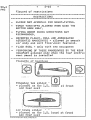
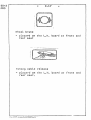
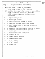
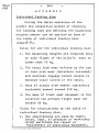
4.7. Assembling and disassembling
and 6/
4.7.1. Tools
50-3
FM3
/Fig. 5
- --
- assembling lever for fitting the spars
- screwdriver
- pliers
- pin for service of tail plane securing
bolt.
4.7.2. Assembling
-------- .....staff:
- - ...... min. 4 persons
4.7.3. Assembling procedures
.......
.-..-----------------
1. Clean and grease the working surfaces
of disconnected fittings and joints o
2. Put the fuselage on the assembly stand
Support the front wheel/tail skid on
the ground/
3. Take off the fuselage upper inspection
door. Rotract the air brake in wings,
set up the brake slider in the cockpit
in the front position and the control
stick in the plane of glider symmetryo
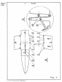
4. Insert the R.H. wing to the fuselage
acc. to Fig. 5 /aileron to the neutral
position# air brake retracted/.
5. Insert the L.H. wing to the fuselage
keeping the ailerons in the neutral
position. Obtain the connection of
pivots and nests, as well as elements
coupling the control system.
After having wings in position lock
the spars finally by the lever installed on spar feet acc. to Fig. 5b.
Insert the main pint insert the tommybar into the hole in glass-fibre member
-
50-3
FM3
4-31
-
and secure with the safety pin.
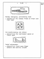
6. Assemble the R.H. half of a tailplane
with the vertical stabilizer acc. to
Fig. 6 /insert the tubular spar end
and the front fixing pivot into proper
neste/.
Connect the control system joint /set up
the elevator and trimming tab properly/.
7. Slide on the L.H. half of a tailplane
on the tubular spar protruding from the
L.H. side of a vertical stabilizer.
Pull forward the protruding end of
securing pin and lock it turning by 90°
Connect the control system joints
/set up properly the elevaror and
trimming~tab/. After connecting the
L.H. half of a tailplane turn the
securing pin by' 90° and press it back
Ired mark must disappear/.
8. Check all the connections and op~ration
of controls. Close the fuselage upper
inspect ion doo,.,.
4.7.4. -_
Assembling
procedures
.....
...... _-------.-.
1. Pull forward the protruding pin securing
the L.H. half of tailplane and lock
turning it by 90° Ired mark on the pin
should be visible/.
2. Take off at first the L.H. and then
the R.H. half of the tailplane /pull
outside applying the oscillating
motions to loosen the connection/.
If necessary beat the carrying tube end
using the hammer and the wooden block.
3. Retract the air brake and take off the
safety-pin which secures the main pin.
Support the wing ends and take out the
pin.
Ur:.J~,:OW
PT 11i.-lako-Oiala / lOOO/ -l b6/ liZ
...
4-32
...
50-3
FM3
4. Support the wing ends, put on the
assembling lever on the spar feet and
loosen the connection of spars with
motion of a lever.
Next support the fuselage and take off
at first the L.H. and next the R.H.
wing.
Install the main pin into the fuselage
fitting and secure with safety-pin.
-
5 ..
Uru:"':OW PT Bidsko-lliala /lOaO/-l6b/lll
5-1
-
-
__
w ____
Fin.
1._
5-2
SZD-50-3
-
PUCHACZ
50-3
FM3
glider
i~~_ _ _ _ _ _ _ _ _ _ _ _ _ _ _ _ _ _~1
-
50-3
FM3
5-3
-
.,
I
~
Cr")
Q)
n
II
~
If
~
!
;
:
- - - -_. - - - --+--&~==-===:---
I
i
I
,
,
\
b
I
:.uui<:OW?T Uielsko-fiiala /7.000/406/ I$l.
Fig. 1
-
5-4
-
Fig. 2. Installation of board instruments.
Glider with two instrument panels.
A
-
8
-
c
-
1
2
3a -
Instrument panel of front seat
Instrument panel of rear seat
Location of panels, ports and ducts
in fuselage
Total pressure port
Static pressure port
Total pressure duct end in fuselage
/bottornj
3b 4
5a -
5b -
6
-
7
-
8
to
9 10 11 -
12 13 -
14 15 16 -
Static pressure duct end in fuselage
/upper/
Rubber ducts
Total pressure duct end of rear
instrument panel
Static pressure duct end of front
instrument panel
Drainage unit
Bottle
Compensator
Airspeed indicator
Variometer
Altimeter
Turn indicator
Compass
Turn indicator battery socket
Turn indicator sWitch
Nuts fixing the rear instrument
panel to canopy
Arrows mark the drainage unit end which
should be disconnected when draining the
installation.
17 18 -
:K-1 tube
K-1 tube duct
50-3
FM3
50-3
r----------
5-5a
-.
-
-
---_.
_--~",J
~
...
~
ml
eql
~I
t;;;;;rUk~:O\rn~p~~~~~--T Bidsko-Oial
a/lOOO/466/HZ
------
~g. ~
F'
I
-
5-6
-
Fig. 2a. Installation of board instruments
Glider wit one instrument panel
1
2
6
7
8
9
10
11
12
13
14
15
-
-
-
-
-
Total pressure port
Static pressure port
Drainage unit
Bottle
Compensator
Airspeed indicator
Variometer
Altimeter
Turn indicator
Compass
Turn iddicator battery socket
Turn indicator swith
Arrows mark the drainage units ends 6,
which should be disconnected when
draining the installation.
16 - K-1 tube duct
50-3
FM3
._.-- - - -
-
50- 3 1
FM3
5-7a
-.-----
. . --..-- . --_.,
,-~
. --
1:
.~.: : : :.
\
-- .
\,
--......
'
\
\
.
---------' -1
--- '-.'-:'
C<)t
"'-\...
~-- . --
---.-----
~L _.
F1g.2a
urui<;()WPT U ..
. dsko -
n·tala
/ lOOO/ -'.66/ III
-
-
5-8
Wiring diagram of electric turn
Fig. 3.
indicator
1
-
Turn indicator
2
-
SWitch
3
-
Batteries
/the poles arrangement
shown on drawing/
50-3
FM3
-
50-3
FM3
5-9
-
.3
2
1
Fig. 3
Druk:UWPT Bi"lsko-lliala / ZOOO/466/HZ
-
5-10
-
Flight measured
Fig. 4.
Speed polar
50-3
Ft13
50-3
5-11
...........
FM3
U)
-!-)
-...
>
',J
............
,;t
a
-
(J)
V
/
o
..
,
-o
CD
;':\
I
o
t(\
,---I
I
I
I
G
I..f\
I
I
I
I
~
I
,,
...........
II
C
.r-!
r.
~
I
I
I
I
I
0
0
FiS-4
'- -- . . _.... -
'-
I
J,
,
N
UJ
/
I
I
0
I'--i
,
D
~
............
0
o
(\j
1'--'\
0
_ _--
,.....
... .. _ .. .....
::'r ....... :c .... PI' U ..dalr.o-Il.&u. i J.O<JO; "f.~! 01.
o
o
o
..:j-
?-=
o
o
t.f\
.. _------
-~
Fig. 50
Winge-fuselage
a/ R.H.
~1ng
L.H.
~ing
bl
-
5-12
6sae~bl1ng
fitted to fuselage
prepared for fitting
Locking the spars by ~eens of asseQbling
lever attached on thrust pivots.
Full arrow: rigging. Broken arrow:
derriging
1
-
Spar root pivots
2
-
Fuselage pivots
3
-
Self-nligning n€Jsts in flings
Control system joints in wings
4
5
-
Air brake control
syste~
joints in
fuselage
Aileron control systeD joints in nings
6
7
-
Aileron control system joints in
fuselage
8
-
Main bolt with
9
10
-
Safety - pin
Spar thrust pivots
11
tom~y-bar
ABs8Qbling lever
P
-
R.H.
ning
L
-
L.H.
\7ing
K
-
Fuselage
50-3
FM3
-
50-3
FM3
5-13
~-----
/~
.. --..
.--
...........
~
---L----
1I
oj
Fig. 5
IJr .. i<:OWPT I3idako-Biala. /1.000/4.66/1ll.
...
Fig. 6.
5-14
..
Assembling of horizontal
tailplane
P
..
L
-
1
-
2,3 4
-
5
...
R.H. half tailplane /with carrying
tubel fitted with fin
L.H. half of tailplane with
trimming-tab
Carrying tube
Carrying tube nests in L.H. half
Pivot fixing fin half
Securing pin in dissecured position
/protruded forward/, secured position
IsmaIl hole in wertical position/.
Red caution sign visible in this
7
-
8
-
9
-
10
-
position disappears when the pin is
pressed in.
Trinning-tab control joint on L.H.
half of control surface
Tri~ming-tab
control joint on
vertical stabilizer
Control joint on elevator
Elevator control joint an vertical
stabilizer
50-3
FM3
-
50-3
FM3
5-15
-
Fig. 6
tlr~;'.;U""·?T
Uielako- Biala /lOOO/4b6/11l
-
-
5-16
Fig. 7.
Colour markings of airspeed indicator
dial
-
red
-
yellow
-
green
50-3
FM3
-
50-3
FM3
5-17
4- 1
.--
FR
xlO
()r~:OWPT l3id5ko-Diala /
lOOO/466/ IlZ
-
-
50-3
FM3
6-1
-
A P PEN 0 I X
IQ~i~!9~~!_!2~~!~g_e!~~
During the daily operation of the
glider the simplified method of checking
the loading mass and defining the balancing
weights amount can be applied on base of
the table of individual loading plan
jpage
6-,3/.
Rules for use the individual loading plan
1. The balancing weights are required only
in solo flight if the pilot's mass is
lower than 70 kg.
2. The total load mass defined as the sum
of real crew mass /parachute included/
and eventual luggage cannot exceed to
maximum value listed in the table.
3. Mass of single crew member /parachute
included/ cannot exceed 110 kg.
4. The mass of front seat occupant in the
inverted two persons flight must not
exceed 95 kg.
Rules for inscriptions to the table of
individual loading plan.
1. The inscriptions are made by Techn.
Check. Dept~ of producer or work-shop
which performed the repair or
replacement of additional equipment.
ur u;..:(y.... PT iHcd.i<o- Bi.la / Z.OOO!4blJ!tsl.
-
6-2a
-
2. Every time two tables are fulfilled: one
recains in this Manual g the second one
is to be stored in the pocket provided
in the cockpit. In case the revision is
made the page 6-3 of Flight Manual should
be replaced with the new one with actual
data.
On the sarne way prepare the ne~ table
on page 6-4 cut it off and place in the
cockpit . .
3. It should be inscribed:
- Fact. No of glider
- Actual additional equipment
/traneceiver oxygen equipment, rear
instrument panel/#
- Empty glider mass with standard
equip~ent and additional equipment
installed.
- Max.total load mass /crew with parachutes and luggage/ equal to the subtracti.on of:
570 kg - total mass of empty glider with
standard equipment and additional
equipment installed.
- Max. pilot 8 mass /parachute included/
on fornt seat defined as the subtraction of max.load mas-pilot's oass
jparachute included/ on
rear ssat.
If the value so calculated exeed 110 kg
the value of 110 kg should be insCribed!
If the inscribed value for two RerSQDS
flight exceeds 95 kg the sign xl
should be added.
- Date, seal and signature of Techn.
Check. Dept ..
NOTE: To define the total mass of the crew and
2
luggage the NOTE of page 2-4a should
be taken into account.
I
50-3
FM3
-
-
6-3
Individual loading plan placard
/copy of glider placard for Flight Manual/
5ZD-50-3 "PUCHACZ"
,I
I Mass
I
i
I
I
I
.
.
.
I
!
i Maximum
I
.
all- up mass
!I
In:
i
i
I Mass
of pilot and parachute
IRear
seat
I
!;
iI
0
0
r
55
I
I~
len
iii::
I
I
1I1
C
0
;~
I~
0
3:
t)~,,~:O'SPT
Front
..
minimum
55
70
55
55
55
55
55
55
55
60
70
80
90
100
110
xl
for
Bid.l<o-f>ia.la /lOOO/46&/1',1.
!
!
the
. . . .
. . . .
. . . . .
r~n~es :~ I.e?,~.
.
- normal
Hight
570 kg
- inverted
flig ht
5~0
I Maximum summarized load mass
I
. .
. .
.
.
.
I
-
.
.
.
.
.
I
i
equipment and
of empty glider with standard
following additional equipment .
.
-
LOADING PLAN
INDIVIDUAL
I
I
-
f3 -. ZD.8
..'7
Fact.. No....
. .. ...).
kg
kg
II
I.
,I
!
I
I
I
[
,i
/98//0 8
1
i
e. crew and luggage ...... kg !
i
kg
Balancing
Date
I.
seat
maximum
70/10 x
110!110 X
110/95 x
weights
pieces:
2
0
110 IllS.
4 10 /88
0
0
0
/08/18
. "8
0
0
98·/6;8
0
0
J/~
1.9:I
g8j$c
inverted flight
Signature
Seal of
Factory
Inspection
16: II. 92
I
I
I
I
oIf~),
-
-
6-4
Individual loading plan placard
/spar placard for the glider/
In case of revision make the inscriptions
ace to new page
the cockpit.
6-3
cut off and place in
SZo-50-3 "PUCHACZ" Fact. No. . . . . . . .
INDIVIDUAL
LOt~DING
Mass of empty glider with standard
following additional equipment .
PLAN
equipment and
the
ranges . . . . . . kg
Maximum all-up mass In:
Maximum summarized
- normal flight 570 kg
- inverted flight 540 kg
load mass i. e. crew and luggage ...... kg
Mass of pilot and parachute
kg
r-------~~--~----------~~
Balancing
seat
weights
pieces:
maximum
r---------+_------~~------_+~--------~
o
55
70
2
t - , - -__0
____+_---7-0--~f__-l:.....;.1...:.0----+_-~0:...---__I
Rear seat
.
.
I~
I~
§
~
a.
~
.-
Front
~------~--------4
55
60
70
55
55
55
55
55
55
55
80
90
100
110
xI
for
11 0 xl
.. .
. ..
. ..
. . .
. . .
. ..
a
a
a
0
a
0
0
inverted flight 95 kg
Date
Signature
Seal 0 f
Factory
Inspec ti 0 n