1
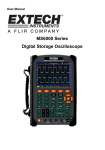
Chapter 9 Specifications Chapter 9 Specifications 9.1 Technical Specifications All specifications herein mentioned apply to the DSO1000S series oscilloscopes. Before checking an oscilloscope from HANTEK to see if it complies with these specifications, make sure it meets the following conditions: The oscilloscope must have been operating continuously for twenty minutes under the specified operating temperature. The Do Self Cal operation must be performed through the Utility menu if the operating temperature changes by more than 5℃. The oscilloscope must be within the factory calibration interval. All specifications are guaranteed unless noted ‘typical’. Oscilloscope Specifications Horizontal Sample Rate Range 1GS/s Waveform Interpolation (sin x)/x Record Length TIME/DIV Range Sample Rate and Delay Time Accuracy Delta Time Measurement Accuracy (Full Bandwidth) Maximum 1M samples per single-channel; maximum 512K samples per dual-channel (4K,16K,40K optional) DSO1062S DSO1122S 4ns/div to 40s/div, in a 2, 4, 8 sequence DSO1202S 2ns/div to 40s/div, in a 4, 8 sequence 2, ±50ppm over any ≥1ms time interval Single-shot, Normal mode ± (1 sample interval +100ppm × reading + 0.6ns) >16 averages ± (1 sample interval + 100ppm × reading + 0.4ns) Sample interval = s/div ‚ 200 DSO1062S DSO1122S Position Range 4ns/div to 8ns/div (-8div × s/div) to 20ms 20ns/div to 80μs/div (-8div × s/div) to 40ms 200μs/div to 40s/div (-8div × s/div) to 400s DSO1202S 2ns/div to 10ns/div DSO1000S Series HandHeld Oscilloscope User Manual (-4div × s/div) to 20ms 69 Chapter 9 Specifications Vertical A/D Converter 8-bit resolution, each channel sampled simultaneously VOLTS Range 2mV/div to 5V/div at input BNC Position Range 2mV/div to 200mV/div, ±2V >200mV/div to 5V/div, ±50V Analog Bandwidth in Normal and Average modes at BNC or with probe, DC Coupled 2mV/div to 20mV/div, ±400mV 50mV/div to 200mV/div, ±2V 500mV/div to 2V/div, ±40V 5V/div, ±50V Selectable Limit, typical 20MHz Analog Bandwidth ≤10Hz at BNC Low Frequency Response (-3db) DSO1062 S DSO1122 S DSO1202S Rise Time at BNC, typical <5.8ns DC Gain Accuracy <3.5ns <1.8ns ±3% for Normal or Average acquisition mode, 5V/div to 10mV/div ±4% for Normal or Average acquisition mode, 5mV/div to 2mV/div Measurement Type: Average of ≥16 waveforms with vertical position at zero Accuracy: ± (3% × reading + 0.1div + 1mV) when 10mV/div or greater is selected DC Measurement Accuracy, Average Acquisition Mode Volts Measurement Repeatability, Average Acquisition Mode Measurement Type: Average of ≥16 waveforms with vertical position not at zero Accuracy: ± [3% × (reading + vertical position) + 1% of vertical position + 0.2div] Add 2mV for settings from 2mV/div to 200mV/div; add 50mV for settings from 200mV/div to 5V/div Delta volts between any two averages of ≥16 waveforms acquired under same setup and ambient conditions Note: Bandwidth reduced to 6MHz when using a 1X probe. DSO1000S Series HandHeld Oscilloscope User Manual 70 Chapter 9 Specifications Trigger Coupling Sensitivity So DSO1062S DSO1122S DSO1202S 1div from DC to 10MHz; 1.5div from 10MHz to Full 1.5div from 10MHz to 100MHz; 2div from 100MHz to Full urce CH DC 1 CH Trigger Sensitivity (Edge Trigger Type) 2 AC Attenuates signals below 10Hz HF Reject Attenuates signals above 80kHz LF Reject Trigger Range Same as the DC-coupled limits for frequencies above 150kHz; attenuates signals below 150kHz Source Level Range CH1, ±8 divisions from center of screen CH2 Trigger Level Accuracy, typical (Accuracy is for signals having rise and fall times ≥20ns) Set Level to 50%, typical Source CH1 Accuracy 、 CH2 0.2div × volts/div within ±4 divisions from center of screen Operates with input signals ≥50Hz Note: Bandwidth reduced to 6MHz when using a 1X probe. Video Type Trigger Source CH1, CH2 Signal Formats and Field Rates, Video Trigger Type Holdoff Range Pulse Trigger Range Peak-to-peak amplitude of 2 divisions Supports NTSC, PAL and SECAM broadcast systems for any field or any line 100ns to 10s Width Pulse Width Trigger Mode Trigger when < (Less than), > (Greater than), = (Equal), or ≠ (Not Equal); Positive pulse or Negative pulse Pulse Width Trigger Point Equal: The oscilloscope triggers when the trailing edge of the pulse crosses the trigger level. Not Equal: If the pulse is narrower than the specified width, the DSO1000S Series HandHeld Oscilloscope User Manual 71 Chapter 9 Specifications trigger point is the trailing edge. Otherwise, the oscilloscope triggers when a pulse continues longer than the time specified as the Pulse Width. Less than: The trigger point is the trailing edge. Greater than (also called overtime trigger): The oscilloscope triggers when a pulse continues longer than the time specified as the Pulse Width. Pulse Range Width Selectable from 20ns to 10s Slope Trigger Slope Mode Slope Point Trigger Trigger Trigger when < (Less than), > (Greater than), = (Equal), or ≠ (Not Equal); Positive slope or Negative slope Equal: The oscilloscope triggers when the waveform slope is equal to the set slope. Not Equal: The oscilloscope triggers when the waveform slope is not equal to the set slope. Less than: The oscilloscope triggers when the waveform slope is less than the set slope. Greater than: The oscilloscope triggers when the waveform slope is greater than the set slope. Time Range Selectable from 20ns to 10s Overtime Trigger The leading edge: Rising edge or Falling edge; Time Setting: 20-10s Swap Trigger CH1 Internal Trigger: Edge, Pulse Width, Video, Slope CH2 Internal Trigger: Edge, Pulse Width, Video, Slope Trigger Frequency Counter Readout Resolution Accuracy (typical) Frequency Range Signal Source 6 digits ±30ppm (including all frequency reference errors and ±1 count errors) AC coupled, from 4Hz minimum to rated bandwidth Pulse Width or Edge Trigger modes: all available trigger sources The Frequency Counter measures trigger source at all times, including when the oscilloscope acquisition pauses due to changes in the run status, or acquisition of a single shot event has completed. Pulse Width Trigger mode: The oscilloscope counts pulses of significant magnitude inside the 1s measurement window that qualify as triggerable events, such as narrow pulses in a PWM pulse train if set to < mode and the width is set to a relatively small time. Edge Trigger mode: The oscilloscope counts all edges of sufficient magnitude and correct polarity. Video Trigger mode: The Frequency Counter does not work. DSO1000S Series HandHeld Oscilloscope User Manual 72 Chapter 9 Specifications Acquisition Acquisition Modes Acquisition Rate, typical Single Sequence Normal, Peak Detect, and Average Up to 2000 waveforms per second per channel (Normal acquisition mode, no measurement) Acquisition Mode Acquisition Stop Time Normal, Peak Detect Upon single acquisition on all channels simultaneously Average After N acquisitions on all channels simultaneously, N can be set to 4, 8, 16, 32, 64 or 128 Inputs Inputs Input Coupling DC, AC or GND Input Impedance, DC coupled 1MΩ±2% in parallel with 20pF±3pF Probe Attenuation 1X, 10X Supported Probe Attenuation Factors 1X, 10X, 100X, 1000X Overvoltage Category CAT I and CAT II Maximum Voltage 300VRMS Category CAT III Maximum Input Voltage (10×), Installation 150VRMS (1×) Installation Category II: derate at 20dB/decade above 100kHz to 13V peak AC at 3MHz* and above. For non-sinusoidal waveforms, peak value must be less than 450V. Excursion above 300V should be of less than 100ms duration. RMS signal level including all DC components removed through AC coupling must be limited to 300V. If these values are exceeded, damage to the oscilloscope may occur. Measurements Voltage difference between cursors: △V Cursors Time difference between cursors: △T Reciprocal of △T in Hertz (1/ΔT) DSO1000S Series HandHeld Oscilloscope User Manual 73 Chapter 9 Specifications Automatic Measurements Frequency, Period, Mean, Peak-to-peak, Cycle RMS, Minimum, Maximum, Rise Time, Fall Time, Positive Width, Negative Width General Specifications Display Display Type Display Resolution Display Contrast 5.7 Inch width TFT Display 480 (Vertical) X 640(Horizontal) pixels Adjustable (16 gears) with the progress bar Probe Compensator Output Output Voltage, typical About 5Vpp into ≥1MΩ load Frequency, typical 1kHz Power Supply Switching Adatper DC Input Power Consumption AC Input:100-240VACRMS,0.6A MAX,50Hz-60Hz; DC Output:9V,2A DC8.5-15V,2A <30W Environmental Temperature Cooling Method Humidity Operating: 32℉ to 122℉ (0℃ to 50℃) Nonoperating: -40℉ to 159.8℉ (-40℃ to +71℃) Convection +104℉ or below (+40℃ or below): ≤90% relative humidity 106℉ to 122℉ (+41℃ to 50℃): ≤60% relative humidity Altitude Mechanical Shock Operating and Nonoperating 3,000m (10,000 feet) Random Vibration 0.31gRMS from 50Hz to 500Hz, 10 minutes on each axis Nonoperating 2.46gRMS from 5Hz to 500Hz, 10 minutes on each axis Operating 50g, 11ms, half sine Length 245mm Height 163mm Depth 52mm Mechanical Size Weight 1.2 Kg Meter Mode Maximum Resolution 6000 Counts DSO1000S Series HandHeld Oscilloscope User Manual 74 Chapter 9 Specifications DMM Testing Modes Voltage,Current,Resistance,Capacitance,Diode Continuity Maximum Input Voltage AC : 600V DC : 800V Maximum Input Current AC : 10A DC : 10A Input Impedance 10MΩ & Meter Specification Range DC Voltage 60.00mV(manual) AC Voltage Resolution ±1%±1digit 10uV 600.0mV 100uV 6.000V 1mV 60.00V 10mV 600.0V 100mV 800V 1V 60.00mV(manual) DC Current Accuracy ±1%±3digit 600.0mV(manual) 100uV 6.000V 1mV 60.00V 10mV 600.0V 100mV 60.00mA ±1.5%±1digit 10uA 600.0mA ±1%±1digit 100uA 6.000A ±1.5%±3digit 1mA 10.00A AC Current 10mA 60.00mA ±1.5%±3digit 10uA 600.0mA ±1%±1digit 100uA 6.000A ±1.5%±3digit 1mA ±1%±1digit 10mA 0.1Ω 10.00A Resistance 600.0 6.000K Capacitance 10uV 1Ω 60.00K 10Ω 600.0K 100Ω 6.000M 1KΩ 60.00M ±1.5%±3digit 10KΩ 40.00nF ±1%±1digit 10pF 400.0nF 100pF 4.000uF 1nF 40.00uF 10nF 400.0uF 100nF Attention:The smallest capacitance value that can be measured is 5nF. Diode 0V~2.0V On-off Test < 10Ω DSO1000S Series HandHeld Oscilloscope User Manual 75 Chapter 9 Specifications Isolation The float voltage between BNC and Grand 600V CAT76 1000V CAT 76 The float voltage between each channel 600V CAT76 1000V CAT 76 The float voltage between multimeter and Grand 1000V Between input Ports directly 400V CAT 76 Input by 10:1 probe 600V CAT76 1000V CAT 76 Linux Feature Kernel Version Linux2.6.30.4 Supported File system Yaffs, Fat32 Sound Driver, Buzzer Driver, FPGA Driver, SPI Driver, Drivers USB Host Driver, LCD Driver, USB massstorage、gadget Driver Linux Applications busybox1.18.4, mplayer, watchdog, gnupg1.4.11 U_boot Version u-boot-1.1.6 Sourcecode website 9.2 download www.hantek.com./download/handscope.zip Accessories All the following accessories are available by contacting your local HANTEK distributor. Standard Accessories Sketch Description X1, X10 two passive probes. The passive probes have a 6MHz bandwidth (rated 100Vrms CAT III) when the switch is in the X1 position, and a maximum bandwidth (rated 300Vrms CAT II) when the switch is in the X10 position. Each probe consists of all necessary fittings. DSO1000S Series HandHeld Oscilloscope User Manual 76