1
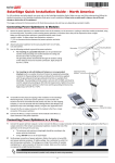
PXP QUICK START GUIDE
TR-SL5-XX-48
REVISION 1.0
FIRMWARE 5.0.6
2010-08-13
TR2033-00
QUICK START GUIDE – TR-SL5-XX-48
SAFETY PRECAUTIONS
•
•
•
•
•
YOU MUST READ AND UNDERSTAND THE FOLLOWING SAFETY INSTRUCTIONS
BEFORE INSTALLING THE DEVICE:
The antenna’s grounding system must be installed in accordance with Articles 810-15, 810-20,
810-21 of the National Electric Code, ANSI/NFPA No. 70-1993. If you have any questions or
concerns about your antenna’s grounding system, please contact a local licensed electrician for
assistance.
Never attach the grounding wire while the device is powered.
Turn off the circuit before attaching any ground wires to an existing electrical circuit.
Only use Tranzeo approved Power-over-Ethernet (PoE) injector for your device.
Never install radio equipment, surge suppressors, or lightening protection during a storm.
LIGHTENING PROTECTION
The key to Lightening Protection is providing a harmless route for lightening to reach the ground. The
system should not be designed to attract lightening, nor can it repel lightening. National, State, and
Local codes are designed to protect life, limb and property, and must always be obeyed.
When in doubt, consult local and national electrical codes or contact a licensed electrician
with expertise in the design and installation of grounding systems.
FCC INFORMATION
This equipment has been tested and found to comply with the limits for Class B digital devices
pursuant to part 15 of the FCC Rules. These limits are designed to provide reasonable protection
against harmful interference when the equipment is operated in a residential environment. This
equipment generates, uses, and can radiate radio frequency energy and, if not installed in
accordance with the instructions in the user manual, may cause harmful interference to radio
communication.
Operation of this equipment in residential areas is likely to cause harmful interference, in which case
users will be required to correct the interference at their own expense. The users should not modify
or change this device without written approval from Tranzeo Wireless. Modification will void warranty
and authority to use the device.
For safety reasons, people should not work in a situation where RF exposure limits could be
exceeded. To prevent this situation, the users should consider the following rules:
•
•
•
•
Install the antenna so that there is a minimum of 100 cm (39.37 in) of distance between the
antenna and people.
Do not turn on power to the device while installing the antenna.
Do not connect the antenna while the device is in operation.
Do not collocate or operate the antenna used with the device in conjunction with any other
antenna or transmitter.
This document is intended for Public Distribution
Page 2 of 17
19473 Fraser Way
Pitt Meadows, BC, Canada V3Y 2V4
Phone (604) 460-6002 Fax (604) 460-6005
www.tranzeo.com
QUICK START GUIDE – TR-SL5-XX-48
Hardware Installation
The TR-SL5 Series radio is easy to install. Please follow the instructions in this guide to install and
set up your device. Before starting, please ensure that all the parts and tools listed below are
available, and determine best location and orientation of the device. Once ready, follow the
instructions on how to install the Ethernet cable, mount the device, ground the device, and take the
necessary steps to properly install and configure your device. TR-AP Quick Start Guide
TR-SL5-XX-48 Radio
Ethernet Boot Cover
L-Bracket and Saddle
Ethernet Boot Gasket
2 ½” U-Bolt
¾” Strain Relief
Nuts for U-Bolt (2)
⅜” Kept Nuts (8)
PoE Injector
Power Cable with DC Plug
Product Kit
Before installation, make sure that you have the following items:
•
•
•
•
•
•
•
•
•
•
1 x TR-SL5-XX-48 Radio
1 x Power over Ethernet (PoE) Injector
1 x Power Cable with DC Plug
1 x Ethernet Boot Cover
1 x Ethernet Boot Gasket
1 x ¾” CAT5t Cable Strain Relief
1 x L-Bracket
8 x 3/8” Kept Nuts
1 x 2 1/2” U-Bolt
2 x Nuts for U-Bolt
If any of the above items is not included or damaged, please contact your local dealer for support.
This document is intended for Public Distribution
Page 3 of 17
19473 Fraser Way
Pitt Meadows, BC, Canada V3Y 2V4
Phone (604) 460-6002 Fax (604) 460-6005
www.tranzeo.com
QUICK START GUIDE – TR-SL5-XX-48
Required Tools
• One 3/8” wrench
• One 1/2” wrench
• One 7/8” wrench
• One TJ-45 Crimper
• CAT5 cable that is long enough to connect the radio to the Power-over-Ethernet (PoE) injector
• 2 RJ-45 Jacks
• #6 Green wire that is long enough to connect the radio to building ground
Site Selection
Before proceeding with the installation, determine the best placement of the device to ensure
optimum RF performance and maximum range. A site survey should be performed to determine
optimal location. For best results, please ensure that the CPE is within line-of-site of the Access
point. Obstructions may impede the performance of the device.
Polarity
Determine if the antenna’s polarization will be horizontal or vertical before installation. The TR-SL5
series radio can be used in either polarity. The Ethernet boot cover should always be placed so that
the cable runs toward the ground for maximum environmental protection.
Power Supply
Only use supplied PoE injector and –48VDC supply to power the TR-SL5-XX-48 radio. Otherwise, the
product may be damaged and will not be covered by the Tranzeo warranty.
This document is intended for Public Distribution
Page 4 of 17
19473 Fraser Way
Pitt Meadows, BC, Canada V3Y 2V4
Phone (604) 460-6002 Fax (604) 460-6005
www.tranzeo.com
QUICK START GUIDE – TR-SL5-XX-48
INSTALLATION GUIDE
Product Description
Back Panel
N-Type Female Antenna Connector
(TR-SL5-N-48 model only)
Studs for L-Bracket (4)
Studs for Boot Cover (4)
RJ-45 Ethernet Jack
LED Indicators Panel
MAC Address
Ground Lug
Serial Number
This document is intended for Public Distribution
Page 5 of 17
19473 Fraser Way
Pitt Meadows, BC, Canada V3Y 2V4
Phone (604) 460-6002 Fax (604) 460-6005
www.tranzeo.com
QUICK START GUIDE – TR-SL5-XX-48
LED Indicators Operation
LED(s)
Color
Indicators
Radio
● Red
On: Radio link
Flashing: Radio activity
Off: No radio link
LAN
● Red
On: Ethernet link
Flashing: Ethernet traffic
Off: No Ethernet link
Power
● Red
On: Powered on
Off: No power or LED’s Disabled
Signal (CPE or PxP Mode)
In CPE mode, LEDS will turn on
sequence to indicate signal
strength based on Signal-to-Noise
level.
● Amber
1 to 10 db above noise
● Amber
11 to 15 db above noise
● Amber
16 to 20 db above noise
● Amber
21 to 30 db above noise
● Amber
31 or more db above noise
LED(s)
Color
Indicators
Signal (AP Mode)
● Amber
On: Radio link
Flashing: Radio activity
Off: No radio link
● Amber
On: Ethernet link
Flashing: Ethernet traffic
Off: No Ethernet link
● Amber
On: Powered on
Off: No power or LED’s Disabled
● Amber
On: ACL enabled
Off: ACL off
● Amber
On: WDS enabled
Off: WDS off
This document is intended for Public Distribution
Page 6 of 17
19473 Fraser Way
Pitt Meadows, BC, Canada V3Y 2V4
Phone (604) 460-6002 Fax (604) 460-6005
www.tranzeo.com
QUICK START GUIDE – TR-SL5-XX-48
Installing the Ethernet Cable
Step
Illustration
Details
1
Insert the CAT5 cable strain relief without the cap nut into the port
opening of the Ethernet boot cover.
2
Using a 3/4” wrench, tighten the strain relief until it touches the boot
cover.
IMPORTANT: Use hand tools only. Do not over tighten.
3
Insert the end of the CAT5 cable through the cap nut of the strain
relief.
4
Pull the end of the CAT5 cable through the strain relief, and then
attach the RJ-45 connector as per the following EIA/TIA-T568B
wiring standards.
This document is intended for Public Distribution
Page 7 of 17
19473 Fraser Way
Pitt Meadows, BC, Canada V3Y 2V4
Phone (604) 460-6002 Fax (604) 460-6005
www.tranzeo.com
QUICK START GUIDE – TR-SL5-XX-48
5
Place the gasket over the 4 studs around the Ethernet port.
6
Plug the CAT5 cable into the Ethernet port, and fit the boot cover
over the 4 studs and gasket. Secure with 4 kept nuts and tighten
using a 3/8” wrench until the gasket is at least 50% compressed. Do
not over tighten.
Remember to place the boot cover according to the desired
polarization, so that the strain relief is pointing down towards ground.
7
Place the cap nut over the strain relief and tighten.
This document is intended for Public Distribution
Page 8 of 17
19473 Fraser Way
Pitt Meadows, BC, Canada V3Y 2V4
Phone (604) 460-6002 Fax (604) 460-6005
www.tranzeo.com
QUICK START GUIDE – TR-SL5-XX-48
Mounting the Radio
Step
Illustration
Details
1
Attach the mounting bracket to the pole using the U-bolt, and secure
the U-bolt with the lock washers and nuts. Align if necessary, and
then tighten the nuts enough to prevent any movement.
2
Down or up tilt can be adjusted by swinging the unit before tightening
the U-Bolt.
3
Fit the radio to the mounting bracket, and secure the radio with the
kept nuts.
IMPORTANT! The strain relief must always be pointing downwards
for maximum environmental protection.
4
Using #6 green grounding wire, connect the grounding lug on the
radio to a proper ground. Refer to Appendix A for more information
on Grounding and Lighting Protection.
This document is intended for Public Distribution
Page 9 of 17
19473 Fraser Way
Pitt Meadows, BC, Canada V3Y 2V4
Phone (604) 460-6002 Fax (604) 460-6005
www.tranzeo.com
QUICK START GUIDE – TR-SL5-XX-48
Connecting the Radio
Step 1: Connect the power wires to –48VDC supply by connecting the solid black wire to the –
48VDC terminal and the black wire with white stripe to the GND terminal.
Step 2: Connect POE Green wire for data line protection to building ground.
Step 3: Plug the power cable into the POE. The POE adapter will be powered on and the power
indicator LED on the top panel will turn on.
IMPORTANT: If the LED doesn’t turn on, then unplug the power cable immediately and
double check wiring and power supply polarity.
Step 4: Connect the CAT5 cable from the radio into the RJ-45 jack marked “CPE” on the POE
adapter. The POE adapter is not weather-proof and should be installed indoors.
Step 5: To configure the TR-SL5 Series radio, connect the Ethernet cable into the RJ-45 jack
marked “PC” on the POE adapter and to the computer network. Ensure that the distance between the
computer and the radio does not exceed 300 ft (90 m).
Note: If connecting to a hub or switch, a crossover cable may be required.
This document is intended for Public Distribution
Page 10 of 17
19473 Fraser Way
Pitt Meadows, BC, Canada V3Y 2V4
Phone (604) 460-6002 Fax (604) 460-6005
www.tranzeo.com
QUICK START GUIDE – TR-SL5-XX-48
Best Practices
1. Always try to run the CAT5 or LMR cable inside the mounting pole whenever possible to help
insulate the cable from air surges.
2. Keep all cable runs as straight as possible. Never put a loop into the cables.
3. Test all grounds to ensure that you are using a proper Ground. If using an electrical socket for
Ground, use a socket tester, such as Radio Shack 22-141.
4. Follow the guidelines in the National Electrical Code Guide.
5. If you are uncertain about the grounding at this location, then drive your own rod and bond it to the
building ground to ensure proper grounding.
This document is intended for Public Distribution
Page 11 of 17
19473 Fraser Way
Pitt Meadows, BC, Canada V3Y 2V4
Phone (604) 460-6002 Fax (604) 460-6005
www.tranzeo.com
QUICK START GUIDE – TR-SL5-XX-48
Configuring the Radio
The TR-SL5 Series radio can be configured through the HTML configuration interface, which is accessible using any
Internet browser.
Before accessing the configuration interface, you have to change the network connection settings in your computer to be
on the same subnet as the radio.
Use the following default values to initially access the radio.
Default IP address:
Default User Name:
Default Password:
192.168.1.100
admin
default
Passwords
When you access the Web Interface for the first time, you will be
required to enter new administrator and recovery passwords. The
recovery password must be different than the administrator password.
Neither of these passwords can be left as default. These passwords
must be changed to access the device. If you do not enter new
passwords, you will be returned to this page.
Network Configuration
By default, Bridge network mode is selected, so all you need to do is
specify IP settings for each radio. If Static IP mode is selected, then
ensure that each radio is assigned a unique IP address. Or, set IP
mode to DHCP Client, if necessary.
This document is intended for Public Distribution
Page 12 of 17
19473 Fraser Way
Pitt Meadows, BC, Canada V3Y 2V4
Phone (604) 460-6002 Fax (604) 460-6005
www.tranzeo.com
QUICK START GUIDE – TR-SL5-XX-48
Wireless Settings for PxP Mode
Point-to-Point (PxP) mode is a Layer 2 transparent protocol optimized for backhaul use. PxP mode is recommended
whenever two network segments are to be bridged.
Wireless Mode X
Set one radio to Access Point (AP) and the other radio to
Infrastructure Station (CPE).
SSID Y
Enter the same SSID on both AP and CPE. Both radios
must have the same SSID to associate. The SSID can have
up to 32 characters.
Visibility Status
Make the AP visible or invisible to clients.
Location
Set the location of the radio to Outdoor or Indoor.
Channel Width
Select the channel width to be used. This value must match
on both AP and CPE.
Channel Z
Select the channel to be used on the AP.
Supported Tx Rates
Select the data rates at which the radios will transmit. Basic rates are indicated with an “*”. All Basic rates supported by
the AP must also be supported by the CPE; otherwise, it may not associate.
Using TX Rate
Set the data rate that the AP and CPE will use to communicate.
Link Distance [
Set the distance between the AP and CPE on both radios. This setting is necessary to define the correct ACK timing.
Setting this value too low or too high will result in low throughput and high retries.
PxP Mode Enabled \
Select on both AP and CPE to enable PxP mode.
PxP MAC Address ]
Enter the MAC address of the CPE on the AP, and the MAC address of the AP on the CPE.
Block Inter-client Traffic
Select on AP to block direct wireless communications between clients in a point-to-multi-point network.
Power Cap
Set the maximum output power for each radio.
Country ^
Select the country where the device is located. Setting an incorrect country may be considered a violation of applicable
laws, as local rules differ in each country.
Antenna Gain _
Specify the gain of the antenna. This information must be set by the installer at the time of installation.
This document is intended for Public Distribution
Page 13 of 17
19473 Fraser Way
Pitt Meadows, BC, Canada V3Y 2V4
Phone (604) 460-6002 Fax (604) 460-6005
www.tranzeo.com
QUICK START GUIDE – TR-SL5-XX-48
Notes:
1. In PxP mode, the Signal LEDs on the radios will operate the same way as in Infrastructure Station mode on
both the AP and CPE, indicating signal strength. See Page 6 for description of signal LEDs operation.
2. Link distance must be set on both AP and CPE, and needs to be within +/-10% of the actual distance to avoid
negative impact on throughput.
3. For optimum performance, at least 4 signal LED’s should be on.
4. Perform Tx and Rx throughput tests across the link using Tranzeo’s ipThroughput program.
5. Set visibility status to Visible during installation for troubleshooting, then change it to Invisible for normal
operation.
6. If encryption is required, use AES encryption to minimize impact on throughput. It’s the most secure and the
device has built-in assist engine for it.
This document is intended for Public Distribution
Page 14 of 17
19473 Fraser Way
Pitt Meadows, BC, Canada V3Y 2V4
Phone (604) 460-6002 Fax (604) 460-6005
www.tranzeo.com
QUICK START GUIDE – TR-SL5-XX-48
APPENDIX A: Lighting Information
What is a proper Ground?
This antenna must be grounded to a proper Earth Ground. According to the National Electrical Code Sections 810-15s
and 810-21, the grounding conductor shall be connected to the NEAREST accessible locations of the following:
a) The building / structure grounding electrode
b) The grounded interior metal water piping system
c) the power service accessible means external to enclosure
d) the metallic power service raceway
e) the service equipment enclosure
f) the grounding electrode conductor
The important thing is to connect to ground at the nearest point.
Why is coiling the LMR or CAT5 bad?
The myth is that lighting follows the path of least resistance. It actually follows the path of least impedance. Coiling
cables creates an air-wound transformer, which lowers the impedance. This means you are in fact making your radios a
more appealing target for surges.
What standard does Tranzeo Wireless equipment meet?
This radio exceeds International Standard IEC 61000-4-5 when properly grounded. For a copy of the full testing report,
see Report Number TRL090904 - Tranzeo Surge Protection board located on the Tranzeo website.
Is lightning damaged covered by the Warranty?
No. Lightning is not covered by the warranty. If you follow the instructions, you chances of lightning damage are greatly
reduced, but nothing can protect a radio from a direct lightning strike.
This document is intended for Public Distribution
Page 15 of 17
19473 Fraser Way
Pitt Meadows, BC, Canada V3Y 2V4
Phone (604) 460-6002 Fax (604) 460-6005
www.tranzeo.com
QUICK START GUIDE – TR-SL5-XX-48
Where to Ground the device
This radio must be grounded at the Pole AND at the POE. This is because the radio is between the Exterior Antenna and
the POE ground. See the examples below
Ungrounded Radio
An ungrounded radio causes the surge to pass through the
radio. In this case the radio most likely will be damaged.
Antenna
Radio
POE
Ground
Grounded Radio
A grounded radio causes the surge to pass directly to ground,
bypassing the radio.
Antenna
Radio
POE
Ground
This document is intended for Public Distribution
Page 16 of 17
19473 Fraser Way
Pitt Meadows, BC, Canada V3Y 2V4
Phone (604) 460-6002 Fax (604) 460-6005
www.tranzeo.com
QUICK START GUIDE – TR-SL5-XX-48
Ungrounded POE
Mounting Pole
In this case, the surge will be picked up by the
Cat 5 cable, and since the POE is not grounded,
the route for the surge is through the radio to
the antenna, and out through the building.
POE
Cat 5 Cable
Grounded POE
Mounting Pole
In this case, the surge will be picked up by the
Cat 5 cable, and since the POE is grounded, the
route for the surge is through the POE to
ground.
Ground
POE
Cat 5 Cable
This document is intended for Public Distribution
Page 17 of 17
19473 Fraser Way
Pitt Meadows, BC, Canada V3Y 2V4
Phone (604) 460-6002 Fax (604) 460-6005
www.tranzeo.com