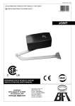
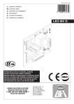
1
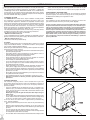
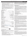
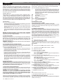
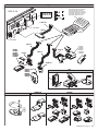
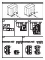
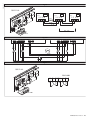
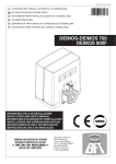
D811419 ver. 07 05-06-07
I
ATTUATORE IN BASSA TENSIONE PER CANCELLI SCORREVOLI A CREMAGLIERA
GB LOW-VOLTAGE ACTUATOR FOR RACK SLIDING GATES
8
027908
231079
DEIMOS BT UL
ISTRUZIONI D’USO E DI INSTALLAZIONE
INSTALLATION AND USER’S MANUAL
Via Lago di Vico, 44
36015 Schio (VI)
Tel.naz. 0445 696511
Tel.int. +39 0445 696533
Fax 0445 696522
Internet: www.bft.it
E-mail: [email protected]
D811419_07
ENGLISH
USER’S MANUAL
Thank you for buying this product, our company is sure that you will be more
than satisfied with the product’s performance. The product is supplied with
a “Warnings” leaflet and an “Instruction booklet”. These should both be
read carefully as they provide important information about safety, installation, operation and maintenance. This product complies with the recognised
technical standards and safety regulations.
1) GENERAL OUTLINE
The DEIMOS BT UL actuator offers ample installation versatility thanks
to its compactness, the extremely low position of its pinion as well as the
height and depth adjustments available. The adjustable electronic torque
limiter ensures antisquash safety. The emergency manual manoeuvre can be
activated very easily by means of a knob. The end-of-run stop is controlled
by electromechanical limit microswitches. The control unit is incorporated.
Before each manoeuvre, the control unit performs a check of the operation
relays and safety devices (photocells, rubber skirt, etc.).
The incorporated control panel checks the drive relays and safety devices
(photocells and safety edge) before carrying out any manoeuvre.
The following optional accessories are available:
- SBBAT mod. Buffer battery kit
It can be incorporated into the actuator, and allows the automation system to
operate even when the mains power supply is disconnected for a short time.
- MSC mod. Release knob (fig.2)
Fixed release knob with personalised key.
2) SAFETY
If correctly installed and used, this automation device satisfies the required
safety level standards. However, it is advisable to observe some practical
rules in order to avoid accidental problems.
Before using the automation device, carefully read the operation instructions
and keep them for future reference.
• Keep children, persons and things outside the automation working area,
particularly during operation.
• Keep radio control or other control devices out of children’s reach, in
order to avoid any unintentional automation activation.
• Do not intentionally oppose the leaf movement.
• Do not attempt to open the gate by hand, if the actuator has not been
released by means of the appropriate release knob.
• Do not modify the automation components.
• In case of malfunction, disconnect the power supply, activate the emergency release to gain access to the actuator and request the assistance
of a qualified technician (installer).
• Before proceeding to any external cleaning operation, disconnect the
mains powers supply and at least one of the battery pole, if fitted.
• Keep the photocell optical components and luminous signal indication
devices clean. Check that the safety devices (photocells) are not obscured
by branches or shrubs.
• For any direct assistance to the automation system, request the assistance
of a qualified technician (installer).
• Have qualified personnel check the automation system once a year.
• Entrance is reserved for vehicles, provide a separate entrance for
pedestrians.
3) MANUAL RELEASE
The manual or emergency release is to be activated when a gate must
be opened by hand, and in all cases where the automation system fails to
operate or operates incorrectly. To carry out the emergency manoeuvre,
proceed as follows:
• Insert the standard key into its appropriate seat (fig. 1) and rotate it anticlockwise (90°), then rotate the release knob clockwise along its entire
stroke. This way the pinion is made to idle, and therefore allows the gate
to be opened by hand.
Warning: Do not push the gate leaf hard, but rather help it along its
entire stroke.
• To reset motor-driven control, rotate the knob anticlockwise along its entire
stroke, and then rotate the standard key clockwise until it is held tight. Keep
the key in a safe place which is known to all the people concerned.
In the case where the release knob is supplied with a personalised key
(fig.2), proceed as follows:
• Insert the personalised key into the lock, rotate the key anticlockwise by
90°.
• Hold the release knob and rotate it clockwise (fig. 2) until it stops. This
way the pinion is made to idle, and therefore allows the gate to be opened
by hand.
• Push the gate leaf by hand, helping it along its entire stroke.
The key cannot be taken out of the lock until the knob is brought back to
its initial position (motor-driven activation).
• To reset motor-driven control, rotate the knob anticlockwise along its entire
stroke, move the key back to its locking position; then take the key out
and keep it in a safe place which is known to all the people concerned.
4) MAINTENANCE AND DEMOLITION
The maintenance of the system should only be carried out by qualified
personnel regularly. The materials making up the set and its packing must
be disposed of according to the regulations in force.
WARNINGS
The installation of the two supplied placards is required in the area of the
gate and in a location where they are clearly visible. (Fig.12).
Correct controller operation is only ensured when the data contained in
the present manual are observed.The company is not to be held responsible for any damage resulting from failure to observe the installation
standards and the instructions contained in the present manual.
The descriptions and illustrations contained in the present manual are
not binding. The Company reserves the right to make any alterations
deemed appropriate for the technical, manufacturing and commercial
improvement of the product, while leaving the essential product features unchanged, at any time and without undertaking to update the
present publication.
Fig. 1
EN
OP
SE
1
2
O
CL
Fig. 2
N
E
OP
MSC
EN
OP
E
OS
CL
E
OS
CL
2
1
DEIMOS BT UL Ver. 07 - INSTALLATION MANUAL
Thank you for buying this product, our company is sure that you will be more
than satisfied with the product’s performance. The product is supplied with
a “Warnings” leaflet and an “Instruction booklet”. These should both be
read carefully as they provide important information about safety, installation, operation and maintenance. This product complies with the recognised
technical standards and safety regulations.
1) GENERAL SAFETY
WARNING! An incorrect installation or improper use of the product
can cause damage to persons, animals or things.
• The “Warnings” leaflet and “Instruction booklet” supplied with this
product should be read carefully as they provide important information
about safety, installation, use and maintenance.
• Scrap packing materials (plastic, cardboard, polystyrene etc) according
to the provisions set out by current standards. Keep nylon or polystyrene
bags out of children’s reach.
• This product was exclusively designed and manufactured for the use
specified in the present documentation. Any other use not specified in
this documentation could damage the product and be dangerous.
• The Company declines all responsibility for any consequences resulting
from improper use of the product, or use which is different from that
expected and specified in the present documentation.
• Do not install the product in explosive atmosphere.
• The Company declines all responsibility for any consequences resulting
from failure to observe Good Technical Practice when constructing closing
structures (door, gates etc.), as well as from any deformation which might
occur during use.
• Disconnect the electrical power supply before carrying out any work on
the installation. Also disconnect any buffer batteries, if fitted.
• Fit an omnipolar or magnetothermal switch on the mains power supply,
having a contact opening distance equal to or greater than 3,5 mm.
• Check that a differential switch with a 0.03A threshold is fitted just before
the power supply mains.
• Check that earthing is carried out correctly: connect all metal parts for
closure (doors, gates etc.) and all system components provided with an
earth terminal.
• Fit all the safety devices (photocells, electric edges etc.) which are needed
to protect the area from any danger caused by squashing, conveying and
shearing.
• Position at least one luminous signal indication device (blinker) where it
can be easily seen, and fix a Warning sign to the structure.
• The Company declines all responsibility with respect to the automation safety
and correct operation when other manufacturers’ components are used.
• Only use original parts for any maintenance or repair operation.
• Do not modify the automation components, unless explicitly authorised
by the company.
• Instruct the product user about the control systems provided and the
manual opening operation in case of emergency.
• Do not allow persons or children to remain in the automation operation
area.
• Keep radio control or other control devices out of children’s reach, in
order to avoid unintentional automation activation.
• The user must avoid any attempt to carry out work or repair on the automation system, and always request the assistance of qualified personnel.
• Anything which is not expressly provided for in the present instructions,
is not allowed.
• Installation must be carried out using the safety devices and controls
prescribed by the EN 12978 Standard.
2) GENERAL OUTLINE
The DEIMOS BT UL actuator offers ample installation versatility thanks
to its compactness, the extremely low position of its pinion as well as the
height and depth adjustments available. The adjustable electronic torque
limiter ensures antisquash safety. The emergency manual manoeuvre can be
activated very easily by means of a knob. The end-of-run stop is controlled
by electromechanical limit microswitches. The control unit is incorporated.
Before each manoeuvre, the control unit performs a check of the operation
relays and safety devices (photocells, rubber skirt, etc.).
The gearmotor (fig.1) comprises:
The incorporated control panel checks the drive relays and safety devices
(photocells and safety edge) before carrying out any manoeuvre.
M Motor.
R
Reduction gear with worm screw and wheel.
F Electromechanical limit switch unit.
P Pinion.
S Release mechanism.
QSC-D UL
Control panel
The following optional accessories are available:
- SBBAT mod. Buffer battery kit
It can be incorporated into the actuator and allows the automation system
12 - DEIMOS
BT UL Ver. 07
to operate even when the mains power supply is disconnected for a short
time. The pack includes (fig.1):
• 2 buffer batteries (ref. B).
• 1 battery holder base (ref. BB).
• 1 battery charger board (ref. SBS).
• Assembly instruction manual.
• Various bolts, screws and cables.
- MSC mod. Release knob (fig.18)
Fixed release knob with personalised key.
•
•
•
•
•
INSTALL THE GATE OPERATOR ONLY WHEN:
The operator is appropriate for the construction of the gate and the usage
Class of the gate,
All exposed pinch points are eliminated or guarded,
The operator is intended for installation only on gates used for vehicles.
Pedestrians must supplied with a separate access opening,
The gate must be installed in a location so that enough clearance is
supplied between the gate and adjacent structures when opening and
closing to reduce the risk of entrapment. Swinging gates shall not open
into public access areas,
The gate must be properly installed and work freely in both directions prior
to the installation of the gate operator. Do not over-tighten the operator
clutch or presure relief valve to compensate for a damaged gate.
For gate openers with hold-to-run control:
• The gate operator controls must be placed so that the user has full view
of the gate area when the gate is moving,
• A sign with the message “WARNING” must be positioned near the
controls. The characters for the writing should be at least 6.4 mm high.
The following statement should also be indicated: “Moving Gate Has the
Potential of Inflicting Injury or Death - Do Not Start Gate Unless Path is
Clear”.
• An automatic closing device (such as a timer, loop sensor, or similare
device) shall not be employed
• No other activation device shall be connected.
Controls must be far enough from the gate so that the user is prevented
from coming in contact with the gate while operating the controls. controls
intended to be used to reset an operator after 2 sequential activations of the
entrapment protection device or devices must be located in the line-of-sight
of the gate. Outdoor or easly accesible controls shall have a security feature
to prevent unauthorized use.
All warnings signs and placards must be installed where visible in the area
of the gate.
For gate operator provided with sensor for contact-free
detection:
• See instructions on the placement of non contact sensor for each type
of application,
• Care shall be exercised to reduce the risk of nuisance tripping, such as
when a vheicle, trips the sensor while the gate is still moving.
• One or more non-contact sensor shall be located where the risk of
entrapment or obstruction exist, such as the perimeter reachable by a
moving gate or barrier.
For gate operator provided with contact detection (rubber edge or similar):
• On or more contact sensor shall be located at the pinch point of a vehicular
vertical pivot gate.
• A hardwired contact sensor shall be located and its wiring arranged so
that the communication between the sensor and the gate operator is not
subjected to mechanical damage.
• A wireless contact sensor such as one that transimts radio frequency
(RF) signals the gate operator for entrapment protection functions shall
be located where the transimission of the signals are not obscrtucted or
impeded y building structure, natural landscaping or similar obstruction.
A wireless contact sensor shall function under the intended end-use
conditions.
•
•
•
IMPORTANT SAFETY INSTRUCTIONS
WARNINGS: to reduce the risk of injury or death:
• Read and follow all instructions.
Never let children operate or play with gate control. Keep the remote
control away from children.
Always keep people and objects away from the gate. NO ONE SHOULD
CROSS THE PATH OF THE MOVING GATE.
All openings of a horizontal slide gate are guarded or screened from the
bottom of the gate to a minimum of 4 feet (1.22 m) above the ground to
D811419_07
ENGLISH
D811419_07
INSTALLATION MANUAL
•
•
•
•
•
•
prevent a 2-1/4 inch (57.2 mm) diameter sphere from passing through
the openings anywhere in the gate, and in that portion of the adjacent
fence that the gate covers in the open position.
All exposed pinch points are eliminated or guarded, and guarding is
supplied for sliding gates exposed rollers.
Test the gate operator monthly. The gate MUST reverse on contact with
a rigid object or stop when an object activates the non-contact sensors.
If the gate operator is not functioning properly, have a qualified service
technician adjust the motor torque setting or the limit of travel and retest
the gate operator.
Failure to retest and to have any necessary adjustments made to the gate
operator so it functions properly can increase the risk of injury or death.
Use the emergency release only when the gate is not moving.
KEEP GATES PROPERLY MAINTAINED. Read the user’s manual. Have
a qualified service person make repairs to gate hardware.
The entrance is for vehicles only. Pedestrians must use a separate entrance.
SAVE THESE INSTRUCTIONS.
3) TECHNICAL DATA
3.1) DEIMOS BT UL Actuator
Power supply:........................................ single-phase 120V ±10% 60Hz (*)
Motor:................................................................................................ 24Vdc
Motor revolutions: .........................................................................3500min-1
Absorbed power:.................................................................................. 70W
Max absorbed power:....................................... 0,5A (120V~) - 1A (110V~)
Reduction ratio: .................................................................................... 1/44
Output revolutions:............................................................................ 79min-1
Pinion pitch:............................................................ 0,157” (4mm) (14 teeth)
Leaf speed:........................................................................ 7,87”/s (0,2 m/s)
Max leaf weight: . ............................................. 1102,3 lb (5000N) (≈500kg)
Max torque:.................................................................... 14,747 lb ft (20Nm)
Impact reaction:...................................................... Electronic torque limiter
Lubrication:..................................................................... Permanent grease
Manual manoeuvre:.............................................. Mechanical knob release
No. manoeuvres in 24 hours:................................................................... 30
Control unit:............................................................................. incorporated
Buffer batteries (optional):......................................... 2 batteries 12V 1.2Ah
Environmental conditions:............................................ from -15°C to +40°C
Degree of protection:............................................................................ IP24
Noise:............................................................................................. < 70dBA
Controller weight:......................................................... 15,4 lb (7kg (≈70N))
Dimensions:................................................................................... See fig.2
Class of gate operator............................................................................. I, II
(*) Special supply voltages on request.
3.2) QSC-D UL Control unit technical data (Fig.17)
Supply to accessories:......................................................... 24V~ (180 mA)
Ampere-stop setting:.............................................. on closing and opening
Automatic closing time: . ....................................................... from 3 to 120s
Working time:....................................................................................... 2 min
Pedestrian opening time:................................................................. 5s fixed
Reverse pause:............................................................................ approx. 1s
Blinker connection:................................................................ 24V max 25W
Fuses:.......................................................................................... See fig.17
Parameter and option setting:.......................................................................
by means of keys or universal palmtop programmer
Incorporated Rolling-Code radio receiver:................ frequency 433.92MHz
Coded by means of :............................................... Rolling-Code Algorithm
No. combinations:.......................................................................... 4 milliard
Antenna impedance: . ..........................................................50Ohm (RG58)
Max no. radio controls to be memorised:................................................. 64
3.3) Transmitter versions which can be used:
all Rolling Code transmitters compatible with
.
4) PRELIMINARY CHECKS
Before proceeding to any installation work, check that the gate structure
conforms to whatever is prescribed by the current standards, and in
particular that:
• The gate sliding track is linear and horizontal, and the wheels are suitable
for supporting the gate weight.
• The gate manual operation can be carried out smoothly along its entire
run, and there is no excessive side slipping.
• A correct play is provided between the upper guide and the gate to ensure
regular noiseless movement.
• The opening and closing gate stops are positioned.
• The established position for gearmotor fixing allows the emergency elements checked do not meet the above requirements, proceed to carrying
out the necessary corrective actions or replacements.
ENGLISH
WARNING: Remember that control devices are intended to facilitate gate
operation, but can not solve problems due to any defects or deficiency
resulting from failure to carry out correct installation or maintenance. Take
the product out of its packing and inspect it for damage. Should it be damaged,
contact your dealer. Remember to dispose of its components (cardboard,
polystyrene, nylon, etc.) according to the current prescriptions.
5) BASE PLATE ANCHORING
5.1) Standard position
• Dig a hole where the cement pad with the buried base plate log bolts is to
be placed in order to fix the reduction gear unit (fig.3). If the sliding track
is already there, digging must be partly carried out in the track foundation
casting. This way, should the track foundation casting sag, the gearmotor
base would also lower, thus maintaining the play between pinion and rack
(approximately 0,039”-0,078” (1-2 mm).
• Position the base plate according to the dimensions specified in fig.4.
• The pinion symbol printed on the base plate must be visible and directed
towards the gate. This also ensures the correct positioning of the raceways
for electrical connections.
• Let the flexible pipes containing electrical cables protrude from the
base plate.
• In order to keep the base plate in its correct position during installation,
it may be useful to weld two iron flat bars under the track, and then weld
the log bolts onto them (fig.3).
• Make a concrete casting in such a way as to embody the base plate
casting into that of the gate track.
• Accurately check that:
The positioning dimensions are correct.
That the base plate is well levelled.
That the 4 stud threads are well clear of cement.
Let the casting harden.
5.2) Other positions
The gearmotor can be positioned in different ways. As an example, fig.5
illustrates a particular type of installation. In the case where the gearmotor
is not fixed on the level of the sliding track (Standard position), you must
ensure that the gearmotor is tightly secured also in relation to the gate position, so as to maintain a correct play 0,039”-0,078” (1-2 mm) between rack
and pinion. The current safety standards with respect to persons, animals
and things must be strictly observed, and in particular risks of accidents due
to squashing in the area of pinion-rack meshing, as well as other mechanical
risks, must be carefully avoided. All the critical spots must be protected
by safety devices in compliance with the current prescriptions.
6) GEARMOTOR FIXING
When the casting has hardened, observe fig. 6 and proceed as follows:
• Position an M10 nut on each of the tie rods, keeping a distance of at least
0,098” (25mm) from the base to allow the gearmotor to be lowered after
the installation is completed, or for subsequent adjustments of the play
between pinion and rack.
• Position a plate “P” supplied as standard on each pair of tie rods and, with
the help of a level, adjust the plane in both directions.
• Remove the cover and screw-cover guard from the gearmotor, and position the reduction gear unit on the four tie rods with the pinion facing
the gate.
• Position the four washers and screw the four gearmotor locking bolts.
• Adjust the depth of the gearmotor, making it slide in the appropriate slots
found in the base, and fix it at a distance between pinion and gate which
is adequate to the type of rack to be installed. The rack teeth must mesh
into the pinion along their entire width. In the paragraph headed “Rack
fitting” we specify the measurements and installation methods of the
most widely used types of rack.
7) RACK FITTING
A rack having a 4 tooth pitch must be fitted to the gate. As far as the length
is concerned, this must include the passage space, as well as the space for
securing the brackets activating the limit microswitches, and for the pinion
meshing section. There are different types of rack, each one differing in
terms of capacity and gate fixing method. The Company markets three
types of racks, which are.
7.1) Mod. CFZ (Fig.8).
Galvanised iron rack - 0,866”x0,866 (22x22mm) section - supplied in 2
- metre lengths - capacity over 4409,2 lb (2000kg (≈ 20000N)). First weld
these pieces onto an adequate iron angle bar and then weld the lot to the
gate. Besides maintaining the distance between the rack and the side of the
gate, the angle bar makes it easy to fix the rack to the gate, even when the
latter is subject to slight side slipping. When join welding the various rack
pieces, you are advised to arrange a section of rack as in (fig.7) to ensure
a correct pitch along the entire length of the rack.
DEIMOS BT UL Ver. 07 - 13
INSTALLATION MANUAL
7.2) Mod. CPZ (Fig.8).
Plastic rack - 22x22mm section - supplied in 3,28ft (1- metre) lengths - max.
capacity 1102,3lb (500kg (≈ 5000N)). This model is to be fixed to the gate
by means of normal or self-threading screws. Also in this case, you are
advised to insert a section of rack the other way round in the joint between
the various pieces, so as to maintain the correct tooth pitch. This type of
rack is quieter and allows height adjustments to be made even after having
been fixed, using the slots provided.
7.3) Mod. CVZ (Fig.8)
Galvanised iron rack - 1,18x0,47“(30x12mm) section - supplied in 3,28ft (1
- metre) lengths - threaded spacers to be welded - max. capacity 4409,2 lb
(2000kg (≈ 20000N)). Having fixed the spacers in the middle of each of the
slots in the various rack pieces, weld the spacers to the gate. Also in this
case, arrange a section of rack the other way round in the joining points of
the various rack pieces to ensure a correct tooth pitch. The screws which fix
the rack to the spacers allow the rack to be adjusted in height.
7.4) Rack fitting
To fit the rack, proceed as follows:
• Activate the emergency release by rotating the appropriate release knob
(See paragraph “Emergency manoeuvre”).
• Rest the rack end on the control pinion and secure it (by welding or using
screws) in correspondence with the pinion, while sliding the gate along
by hand (fig. 9).
• In the case of incorrect gate alignment (excessive side curving) which
cannot be corrected, place a few shims between the rack and gate in
order to ensure continuous centring of the rack with respect to the pinion
(fig. 10).
DANGER - The welding operation is to be carried out by a competent
person who must be provided with all the personal protection equipment
required by the current safety standards.
8) PINION ADJUSTMENT
Having finished fixing the rack, the rack-pinion play needs to be adjusted to
approximately 0,078”(2mm) (fig.6): this is obtained by slackening the four
M10 nuts under the gearmotor base by approximately 0,078”(2mm), and
then securing the four upper nuts. Make sure that the rack and pinion are
aligned and centred (fig.10).
WARNING - Remember that the rack and pinion life strictly depends
on their correct meshing.
9) ELECTROMECHANICAL LIMITING DEVICES
The operation must be carried out with the emergency release activated and
the mains power supply disconnected. The runners which control the limiting
devices are to be positioned at both ends of the rack.
- Push the gate fully open by hand.
- Position the opening end-of-stroke runner (fig.11) so that it intercepts the
microswitch control lever and makes it trigger. Having identified the correct
position, tighten the runner screws.
- Push the gate fully closed by hand.
- Position the closing end-of-stroke runner (fig.11) so that it intercepts the
microswitch control lever and makes it trigger. Having identified the correct
position, tighten the runner screws.
- The runners must lock the gate before this intercepts the mechanical
backstops placed on the track.The closing end-of-stroke runner adjustment
must be made in such a way as to leave a clearance of approximately
50mm between the gate and the fixed swing leaf, as prescribed by the
current safety standards, otherwise fit an electric edge at least 50mm
thick (fig.12).
10) GATE BACKSTOPS
DANGER - The gate must be provided with mechanical backstops, both
on opening and closing, in order prevent it from coming out of the upper
guide (fig.13); the backstops must be tightly secured to the ground, a
few centimetres beyond the electrical stop point.
11) ELECTRICAL INSTALLATION SETUP
Lay out the electrical installation as shown in fig.14 with reference to the CEI
64-8 and IEC364 provisions complying with the HD384 and other national
standards in force for electrical installation.
WARNING! For connection to the mains, use a multipolar cable having
a minimum cross section of 3x16 AWG and complying with the current
standards. (For example, if the cable is not protected, it must be at least
equal to H07 RN-F, whereas if it is protected it must be at least equal
to H07 VV-F with a 3x16 AWG sq cross section).
Connect the control and safety devices in compliance with the previously
mentioned technical installation standards. The cables (mains and auxiliary)
must be distinctly separated. Fig.14 shows the number of connections and
14 - DEIMOS
BT UL Ver. 07
their cross sections for a length of approximately 328,08 ft(100 metres); for
greater lengths, calculate the cross section for the true automation load.
The main automation components are (fig.14):
I
Type-approved adequately rated omnipolar circuit-breaker with
at least 0,14”(3,5 mm) contact opening, provided with protection
against overloads and short circuits, suitable for cutting out automation from the mains. If not already install ed, place a type-approved
omnipolar circuit-breaker with a 0.03A threshold just before the
automation system.
QR Control panel with built-in receiver
S Key selector.
AL
Blinker with tuned antenna.
M
Actuator
P
Wall-mounted pushbutton panel.
Fte, Fre Pair of external photocells.
T
1-2-4 channel transmitter
C
Rack
ANTENNA INSTALLATION
Use an antenna tuned to 433MHz.
For Antenna-Receiver connection, use RG8 coaxial cable.
The presence of metallic masses next to the antenna can interfere with radio
reception. In case of insufficient transmitter range, move the antenna to a
more suitable position.
12) TERMINAL CONNECTIONS
After adequate electric cables have been made to pass through the raceways
and the various automation components fixed to the chosen points, these
must be connected according to the instructions and diagrams shown in the
relevant instruction manuals. Connect the phase, neutral and earth (compulsory) cables. The mains cable is to be secured in the appropriate cable
clamp (fig.15- ref. P1), the accessory cables in their cable clamp (fig.15- ref.
P2), and the protection (earth) wire, having a yellow/green insulating sheath,
must be held in its appropriate wire clamp (fig.15 - ref. S).
The automation device is to be set at work after all the safety devices have
been connected and checked. See the terminal diagram in fig.16.
JP2
1-2 Motor connection (1 Blue - 2 Red).
3-4 Transformer secondary circuit 24V.
WARNING – If the opening direction is not correct, reverse connections
1 and 2 for the motor and connections 6 and 7 for opening and closing
limit switches.
JP3
5-6 Closing limit switch SWC (5 Black common - 6 Red)
5-7
Opening limit switch SWO (5 Black common - 7 Brown)
8-9 Blinker 24V max 25W.
10-11 Antenna (10 signal - 11 braid)
12-13 Power supply for accessories:
24 V~ operation with power supply on
24 V (12+,13-) operation with power supply off and optional battery
back up. Mod. SB BAT
14-15 24 V~ output for acoustic signal (Fig. 19A).
16-17 Output for power supply to safety devices (photocell transmitter and
safety edge transmitter)
N.B.: output only active during the manoeuvre cycle
24 V~ operation with power supply on
24 V (16-,17+) operation with power supply off and optional battery
back up. Mod. SB BAT.
18
Input for safety devices FAULT (see item 13).
19-20 Pedestrian control button PED (N.O.) Opens the gate for 5 seconds
according to the logic set (3 or 4 steps).
21-22 START/CLOSE control button and key selector (N.O.).
21-23 STOP control button (N.C.). In all cases, stops the operator until the
next Start command. If not used, leave bridged.
21-24 Input for photocell PHOT (see item 13). If not used, leave bridged.
21-25 BAR electric edge contact input (N.C.). In case of triggering, movement
is stopped and reversed for about 3s. If not used, leave bridged.
21-26 OPEN control button (N.O.)
JP1
31-32 Transformer primary circuit 120V~.
33-34 Single-phase power supply 120V~, 60Hz (33N - 34L).
13) CONNECTION TO SAFETY DEVICES
Note: only use safety devices which can receive with a free changeover
contact (refer to Fig.19).
D811419_07
ENGLISH
D811419_07
INSTALLATION MANUAL
To connect the photocells refer to the diagram in fig. 19 taking into account the
number of pairs used: 1 pair box 1C, 2 pairs box 2C. The control unit performs
the test of 2 safety devices. The additional devices must be equipped with
internal self-diagnosis and connected in series. If photocells are not used,
leave the jumpers aligned between terminal 21/23, and between terminal
21/24 of the QSC D UL board. The connection of the infrared rubber skirt
must be performed in the same way as for the photocells, i.e. by energizing
the transmitter from terminal 16/17 and the receiver from terminal 12/13.
14) PROGRAMMING
The control panel provided with a microprocessor is supplied with function
parameters preset by the manufacturer, suitable for standard installations.The
predefined parameters can be altered by means of either the incorporated
display programmer or universal palmtop programmer.
In the case where programming is carried out by means of universal palmtop
programmer, carefully read the instructions relating to universal palmtop
programmer, and proceed in the following way.
Connect the universal palmtop programmer to the control unit through the
UNIFLAT and UNIDA accessories (See fig. 17). The QSC-D UL control unit
does not supply the universal palmtop programmer with power, and therefore
requires an appropriate supply unit.
Enter the “CONTROL UNITS” menu, and the “PARAMETERS” submenu, then
scroll the display screenfuls using the up/down arrows to set the numerical
values of the parameters listed below.
For the function logics, refer to the “LOGIC” submenu.
In the case where programming is carried out by means of the incorporated
programmer, refer to Fig. A and B and to the paragraph on “Configuration”.
N.B.: The QSC-D UL control unit cannot supply the universal palmtop
programmer with power.
15) CONFIGURATION
The display programmer is used to set all the QSC-D UL control panel
functions.
The programmer is provided with three pushbuttons for menu scrolling and
function parameter configuration:
+ menu scrolling/value increment key
- menu scrolling/value reduction key
OK Enter (confirm) key
The simultaneous pressure of the + and - keys is used to exit the active
menu and move to the preceding menu.
The modifications made are only set if the OK key is subsequently pressed.
When the OK key is pressed for the first time, the programming mode is entered.
The following pieces of information appear on the display at first:
- Control unit software version.
- Number of total manoeuvres carried out (the value is expressed in
hundreds, therefore the display constantly shows 0000 during the first
hundred manoeuvres).
- Number of manoeuvres carried out since the latest maintenance operation (the value is expressed in hundreds, therefore the display constantly
shows 0000 during the first hundred manoeuvres).
- Number of memorised radio control devices.
When the OK key is pressed during the initial presentation phase, the first
menu can be accessed directly.
Here follows a list of the main menus and the respective submenus available.
The predefined parameter is shown between square brackets [ 0 ].
The writing appearing on the display is indicated between round brackets.
Refer to Figures A and B for the configuration procedure.
15.1) Parameters menu
- Automatic Closing Time (TCA) [ 10s ]
Set the numerical value of the automatic closing time from 3 to 120
seconds.
- Opening Motor torque (op. t) [ 80% ]
Set the numerical value of the motor torque between 1% and 99%.
- Closing Motor torque (cls. t) [ 80% ]
Set the numerical value of the motor torque between 1% and 99%.
- Slow-down opening motor torque (op. t slow) [ 50% ]
(parameters ⇒ address 8)
Set the numerical value of the motor torque between 1% and 99%.
- Slow-down closing motor torque (cls. t slow) [ 50% ]
(Advanced parameters ⇒ address 9)
Set the numerical value of the motor torque between 1% and 99%.
- Fast Opening Time (op. speed. time) [ 15 s. ]
(Advanced parameters ⇒ address 6)
Set the time ato normal opening speed (not slowed down), ranging from
1 second to 2 mins.
-
-
-
ENGLISH
Fast Closing Time (cls. speed. time) [ 15 s. ]
(Advanced parameters ⇒ address 7)
Set the time to normal closing speed (not slowed down), ranging from 1
second to 2 mins.
Note: The slow-down time, on closing and on opening, is obtained by
timing one manoeuvre, and setting a lower value within this parameter. If,
for example, one manoeuvre lasts 15 seconds, set “normal speed time”
to 12s to obtain 3s of slow-down time.
Slow-down speed (slov speed) [ 0 ]
(Advanced parameters ⇒ address 5)
Set the slow-down speed by choosing from one of the following values:
0 – slow down disabled
1 – slow down at 50% of normal speed
2 – slow down at 33% of normal speed
3 – slow down at 25% of normal speed
Zone (zone) [ 0 ] (Advanced parameters ⇒ address 1)
Set the zone number between a minimum value of 0 and a maximum
value of 127. See paragraph on “Serial connection”.
15.2) MENU LOGIQUES (logic)
- TCA (TCA) [ OFF ]
ON Activates automatic closing
OFF Excludes automatic closing
- 3 Steps (3 step) [ OFF ]
ON Enables 3-step logic. A Start impulse has the following effects:
door closed: opens
on opening: stops and enters TCA (if configured)
door open: closes
on closing: stops and reopens
OFF Enables 4-step logic. A Start impulse has the following effects:
door closed: opens
on opening: stops and enters TCA (if configured)
door open: closes
on closing: stops and does not enter TCA (stop)
after stopping: opens
- Impulse lock (ibl open) [ OFF ]
ON The Start impulse has no effect during the opening phase.
OFF The Start impulse becomes effective during the opening or closing
phase.
- Photocells on opening (photc. open) [ OFF ]
ON: In case of obscuring, this excludes photocell operation on opening. During the closing phase, it immediately reverses the motion.
OFF: In case of obscuring, the photocells are active both on opening and
on closing. When a photocell is obscured on closing, it reverses the
motion only after the photocell is disengaged.
- Photocell test (test phot) [ OFF ] (Advanced logics ⇒ address 14)
ON Activates photocell check
OFF Deactivates photocell check
If this setting is not activated (OFF), it inhibits the photocell checking
function, allowing connection of devices not provided with additional
checking contact.
- Prealarm (preal) [ OFF ]
ON The blinker comes on about 3s before the motors start.
OFF The blinker comes on at the same time as the motors start
- Hold-to-run control (hold-to-run) [ OFF ]
ON Hold-to-run operation: the manoeuvre continues as long as the control
key is kept pressed.(OPEN-CLOSE)
OFF Impulse operation, according to the 3 or 4 step logic.
- Start-Close selection (start - close) [ OFF ]
ON The input between the two terminals 21-22 acts as close
OFF The input between the two terminals 21-22 acts as start
Fixed code (fixed code) [ OFF ]
(Advanced logics ⇒ address 13)
ON The receiver is configured for operation in fixed-code mode, see
paragraph on “Radio Transmitter Cloning”.
OFF The receiver is configured for operation in rolling-code mode, see
paragraph on “Radio Transmitter Cloning”.
Radio transmitter programming (radio prog) [ ON ]
(Advanced logics ⇒ address 15)
ON This enables transmitter storage via radio:
1 – First press the hidden key (P1) and then the normal key (T1, T2,
T3 or T4) of a transmitter already memorised in standard mode by
means of the radio menu.
2 – Within 10s press the hidden key (P1) and the normal key (T1, T2,
T3 or T4) of a transmitter to be memorised.
The receiver exits the programming mode after 10s, other new transmitters can be entered before the end of this time.
This mode does not require access to the control panel.
DEIMOS BT UL Ver. 07 - 15
INSTALLATION MANUAL
OFF This disables transmitter storage via radio.
The transmitters can only be memorised using the appropriate Radio
menu.
- Loop (loop) [ OFF ] (Advanced logics - address 11)
ON In the case of a closed loop centralised connection (Fig.20), set the
control unit to ON.
OFF In the case of an open centralised connection (Fig.20), set the control
unit to OFF.
- Master/Slave (Master) [ OFF ] (Advanced logics - address 12)
ON The control panel is set as Master in a centralised connection.
OFF The control panel is set as Slave in a centralised connection.
15.3) RADIO MENU (RADIO)
Add
Allows you to add one key of a radio control device to the receiver
memory; after storage it displays a message showing the receiver
number in the memory location (from 01 to 64).
Add Start button (add start)
associates the required key to Start command
For transmitters with hidden key, press hidden key P1 (fig. B1).
For transmitters without hidden key, the key P1 function corresponds
to simultaneously pressing the 4 transmitter keys or, after opening
the battery compartment, bridging the two P1 points by means of a
screwdriver (fig. B2).
Read (read)
Checks one key of a receiver; if stored it displays a message showing
the receiver number in the memory location (from 01 to 64), and the
key number (T1, T2, T3 or T4).
Eliminate list (erease 64)
WARNING! Completely removes all memorised radio control devices
from the receiver memory.
Receiver code reading (RX code)
This displays the code entered in the receiver.
IMPORTANT NOTE: STICK THE adhesive KEY LABEL ON THE FIRST
MEMORISED TRANSMITTER (MASTER).
In the case of manual programming, the first transmitter assigns the RECEIVER KEY CODE; this code is necessary in order to carry out subsequent
cloning of radio transmitters.
The on-board Clonix incorporated receiver is provided with a number of
advanced functions:
• Cloning of master transmitter (rolling-code or fixed code)
• Cloning by replacement of transmitters already inserted in the receiver
• Management of transmitter database
• Management of common receivers
To use these advanced function, refer to the universal palmtop programmer
instructions and the CLONIX programming guide, supplied with the universal
palmtop programmer device.
15.4) LANGUAGE MENU (language)
Allows you to set the language on the display programmer.
- ITALIAN (ITA)
- FRENCH (FRA)
- ENGLISH (ENG)
- SPANISH (ESP)
15.5) DEFAULT MENU (default)
Restores the preset default values on the control unit. After restoring, a new
autoset operation must be carried out.
15.6) DIAGNOSTICS AND MONITORING
The display on the QSC-D UL panel shows some useful information, both
during normal operation and in the case of malfunctions.
Diagnostics:
In the case of malfunctions, the display shows a message indicating which
device needs to be checked:
PED = Pedestrian input activation
STRT = START input activation
STOP = STOP input activation
PHOT = PHOT input activation
BAR = COST input activation
FLT = FAULT input activation for checked photocells
CLOS = CLOSE input activation
OPEN = OPEN input activation
SWO = Opening limit switch input activation
SWC = Closing limit switch input activation
TH
= Activation of software thermal protection
16 - DEIMOS
BT UL Ver. 07
In the case where an obstacle is found, the QSC-D UL panel stops the door
and activates a reverse manoeuvre; at the same time the display shows the
“AMP” message.
Monitoring:
During the opening and closing phases, the display shows four digits separated by a dot, for example 35.40. The digits are constantly updated during
the manoeuvre, and represent the maximum torque reached by motor 1 (35)
and the selected torque (40).
These values allow the torque setting to be corrected.
If the maximum torque value reached during the manoeuvre gets sensibly
close to the value set in the parameter menu, malfunctions may occur in the
future following wear or slight door deformation.
It is therefore advisable to check the maximum torque reached during some
of the manoeuvres carried out in the course of installation, and if necessary
set a value about 15-20 percent points higher in the parameter menu.
15.7) AUTOSET MENU (autoset)
Allows you to automatically set the Motor torque.
WARNING! The autosetting operation is carried out from closing end-ofstroke devices. If Autoset is commanded in a different position an error
message indicating “nsvc” will be displayed and the required manoeuvre
will not take place.
WARNING!! The autoset operation is only to be carried out after checking the
exact leaf (opening/closing) movement, and correct limit-switch activation.
Set the adequate slow-down speed: by pressing OK the message “.... .... ....”
is displayed and the control unit commands an opening manoeuvre without
slow-down, followed by a closing manoeuvre without slow-down during which
the duration of the stroke is memorised. Then, the control unit commands a
second opening manoeuvre with slow-down followed by a second closing
manoeuvre with slow-down during which the minimum torque value necessary for the movement of the leaf is automatically set. Then the control unit
sets a slow-down speed of 8 sec. If the stroke lasts less than 8 seconds, the
control unit sets a slow-down time equal to half stroke.
During this phase, it is important to avoid obscuring the photocells, as well as
using the STRT, STOP, PED, CLOS or OPEN commands and the display.
After this, if autosetting has been successfully completed, the control unit displays
the “OK” message and, after pressing any key, returns to the Autoset menu.
If, on the other hand, the control unit displays the “KO” message, it means
that the autoset procedure has not been successfully completed; it is thus
necessary to check the wear condition of the gate and the regular movement
of the leaves before proceeding to a new autoset operation.
WARNING! During the autoset phase, the obstacle detection function is
not active, therefore the installer must control the automation movement
and prevent persons and things from approaching or standing within the
automation working range.
In the case where buffer batteries are used, autosetting must be carried out
with the control panel supplied by mains power voltage.
WARNING: the torque values determined by autosetting refer to
the slow-down speed determined by autosetting. When modifying
the slow-down speed, the slow-down torque values must be modified
as well so that activation of the safety device takes place according
to the new speed set.
Incorrect sensitivity setting can cause injuries to persons or
animals, or damage to things.
16) SERIAL CONNECTION USING SCS1 BOARD (Fig.20).
The QSC-D UL control panel allows several automation units to be connected
in a centralised way by means of appropriate serial inputs and outputs (SCS1).
This makes it possible to use one single command to open and close all the
automation units connected.
Following the diagram in Fig. 20, proceed to connecting all the QSC-D UL
control panels, exclusively using a telephone-type line.
Should a telephone cable with more than one pair be needed, it is indispensable to use wires from the same pair.
The length of the telephone cable between one appliance and the next
must not exceed 820,2ft (250 m).
At this point, each of the QSC-D control panels must be appropriately configured, by setting a MASTER unit first of all, which will have control over all
the others, to be necessarily set as SLAVE (see logic menu).
Also set the Zone number (see parameter menu) between 0 and 127.
The zone number allows you to create groups of automation units,
each one answering to the Zone Master unit. Each zone can only be
assigned one Master unit, the Master unit in zone 0 also controls the Slave
units in the other zones.
Loop closing of the serial connection (indicated by a dotted line in Fig.20)
is only needed if you require to check the no. of the connected devices by
means of universal palmtop programmer.
16.1) Opposite sliding leaves (Fig. 20A)
Serial connection also provides centralized control of two opposite sliding
gates (Fig. 20A).
D811419_07
ENGLISH
D811419_07
INSTALLATION MANUAL
In this case, the Master M1 control board will perform closing and opening
of Slave M2 control board simultaneously.
In case of opposite sliding leaves, the M1 (master) control board and the
M2 (slave) control board should bear the same area number without other
devices being connected in such area.
If the opening direction of one of the two motors is incorrect, invert the
connection 1 and 2 of the motor as well as the connections 6 and 7 of the
opening and closing limiting devices.
The safety devices (photocells and sensing edges) should be connected
according to the diagram in Fig. 20A.
To connect checked safety devices, make reference to whatever is specified
in previous paragraph 13. Carry out connections on the MASTER control
unit and only bring the cable of terminal 24 to the SLAVE control unit. On the
SLAVE control unit, the TEST PHOT switch must be left on OFF.
The Start, Open, Close, push-buttons and the Timer contact should be
normally connected to the M1 (master) control board.
The pedestrian command is to be connected to the M2 panel (slave).
The Stop command provides greater safety and is generated by a double contact
NC push-button connected to both control boards as shown in Fig. 20A.
NOTE: Disable the TCA function from the M2 (slave) panel.
17) Statistics
Having connected the universal palmtop programmer to the control unit, enter
the CONTROL UNIT / STATISTICS menu and scroll the screenful showing
the statistical parameters:
- Board microprocessor software version.
- Number of cycles carried out. If motors are replaced, count the number
of manoeuvres carried out up to that time.
- Number of cycles carried out from the latest maintenance operation.
It is automatically set to zero after each self-diagnosis or parameter writing.
- Date of latest maintenance operation. To be updated manually from the
appropriate menu “Update maintenance date”.
- Installation description. 16 characters can be entered for installation
identification.
18) ALARM SIGNAL
The operator is provided with an alarm siren managed from the control panel.
The alarm signal is set off in the case where the obstacle detection device
(amperostop) is activated twice, without the leaf being brought to its fully
opened or closed position.
In the case of malfunctions, any alarm activation immediately stops all
manoeuvres.
The acoustic signal can be interrupted using the STOP button.
In the case of alarm activation, proceed to the following checks:
1) Check that the gate has not met any obstacles.
2) Check that the sliding track is clean and free from any debris along the
entire leaf stroke.
3) Check that the sliding wheels on the leaf are undamaged and correctly
positioned along the track.
19) MANUAL RELEASE
The manual or emergency release is to be activated when you have to open
the gate by hand, and in any event of failed or incorrect operation of the
automation system. To carry out the emergency manoeuvre, you have to:
• Insert the release knob in its appropriate seat (fig.18) and rotate it clockwise
along its entire travel. This way you set the pinion idling, thus allowing to
gate to be opened by hand.
Warning: Do not push the gate leaf hard, but help it along its
entire stroke.
• To reset motorised control, rotate the knob anticlockwise along its entire
travel, remove the knob and leave it in a safe place which is known to all
the persons concerned.
In the case where a release knob with personalised key is fitted (fig.18),
proceed as follows:
• Insert the personalised key in the lock, and rotate the key anticlockwise.
• Grip the release knob and rotate it clockwise (fig.18) until it stops.
• Push the gate leaf by hand and help it along its entire travel.
• The key cannot be removed from its lock until the knob is returned to its
initial position (motorised activation).
• To reset motorised control, rotate the knob anticlockwise along it entire
travel and remove the key.
•
•
•
ENGLISH
Check the opening and closing operations with the control devices in
use.
Check the standard and customised electronic functioning logic.
The installation of the two supplied placards is required in the area of
the gate and in a location where they are clearly visible. (Fig.12).
21) AUTOMATION OPERATION
Since the automation can be remote-controlled by means of a remote control
device or a start button, and so out of sight, the good working order of all the
safety devices should be checked regularly. In the event of any anomalous
functioning of the safety devices, consult a specialised technician immediately.
Keep children at a safe distance from the automation operation area.
22) CONTROL
The automation is used for the power-operated opening and closing of the
gate. The control can be of a number of types (manual, remote-controlled,
magnetic badge access control, etc.) depending on requirements and the
characteristics of the installation. See the specific instructions for the various
control systems. Users of the automation must be instructed about its control
and operation.
23) MAINTENANCE
Disconnect the power supply when carrying out any maintenance operations.
• Clean the lenses of the photocells every so often.
• Have a qualified person (installer) check correct motor torque setting.
• In the event of any anomalous functioning which cannot be resolved,
disconnect the power supply and contact a specialised technician (installer). Whilst the automation is out of order, activate the manual release
to allow manual opening and closing.
24) SCRAPPING
WARNING! This operation should only be carried out by qualified personnel.
Materials must be disposed of in conformity with the current regulations.
In case of scrapping, the automation devices do not entail any particular risks
or danger. In case of materials to be recycled, these should be sorted out by
type (electrical components, copper, aluminium, plastic etc.).
25) DISMANTLING
WARNING! This operation should only be carried out by qualified personnel.
When the automation system is disassembled to be reassembled on another
site, proceed as follows:
• Disconnect the power supply and the entire external electrical installation.
• In the case where some of the components cannot be removed or are
damaged, they must be replaced.
WARNINGS
Correct controller operation is only ensured when the data contained
in the present manual are observed. The company is not to be held
responsible for any damage resulting from failure to observe the
installation standards and the instructions contained in the present
manual.
20) AUTOMATION CHECK
Before allowing the automation to be used normally, carry out the following
procedure very carefully:
• Check the correct functioning of all safety devices (limit microswitches,
photocells, sensitive edges etc.).
• Check that the thrust (anti-squash) force of the leaf is within the limits
set by current regulations.
• Check the manual opening command.
DEIMOS BT UL Ver. 07 - 17
LEGENDA
ACCESS TO MENUS
+-
Press the OK key
OK
[ ]
$2
OK
OQABSJ
/ON
/OFF
Control unit software version
No. total manoeuvres
(in hundreds)
No. manoeuvres since latest
maintenance (in hundreds)
No. radio control devices
memorised
OK
- +
OK
Preset value
.0%
Parameter increment/reduction
or ON/OFF commutation
Simultaneously press the + and - keys.
Simultaneous pressure of the + and – keys
allows you to exit the active menu and return to
the preceding menu; if this takes place at the
main menu level, programming is exited and
the display switched off.
The modifications made are only confirmed if
the OK key is subsequently pressed.
Message: Programming in progress
Message: KO! (value or function error)
Press OK key (Enter/confirm)
Menu scrolling
(+ = preceding - = following)
Message: “Wait” (enter value or function)
+.P+
OK
RA
OK
[ ]
OK
.P%
OK
[ ]
OK
.P%
OK
[]
OK
.P%
OK
[ ]
OK
.P%
OK
[ ]
OK
.P%
OK
[ ]
OK
.P%
OK
[ ]
OK
.P%
OK
[ ]
OK
.P%
OK
[
]
OK
.P%
- +
+-
-. 2
- +
$',#
!*1 2
- +
MN RQJMU
- +
- +
AJQ RQJMU
- +
LMPK MN QNCCB
- +
LMPK AJQ QNCCB
- +
QJMUQNCCB
- +
8MLC
+*M%'A
OK
RA
PARAMETER MENU
[M$$]
ON
OFF
OK
OK
[M$$]
ON
OFF
OK
.P%
OK
[M$$]
ON
OFF
OK
.P%
OK
[M$$]
ON
OFF
OK
.P%
OK
[M$$]
ON
OFF
OK
.P%
OK
[M$$]
ON
OFF
OK
.P%
OK
[M$$]
ON
OFF
OK
.P%
OK
[M$$]
ON
OFF
OK
.P%
OK
[M$$]
ON
OFF
OK
.P%
OK
[ML ]
ON
OFF
OK
.P%
OK
[M$$]
ON
OFF
OK
.P%
OK
[M$$]
ON
OFF
OK
.P%
OK
.P%
- +
+-
QRCN
- +
$',#
G@JMNCL
- +
NFMRMAMNCL
- +
R#QR.FMR
- +
- +
NPC?J
- +
FMJBRMPSL
- +
QR?PRAJMQC
- +
FOLLOWING MENUS
FIG. B
DGVCBAMBC
- +
P?BGMNPME
- +
*MM.
- +
+1R#P
18 - DEIMOS
BT UL Ver. 07
TCA (automatic closing time)
value expressed in seconds
(default 10=10s, min 3=3s, max 120=120s)
Opening Motor torque – value
expressed in % (default 80%, min 1%, max
99%)
Closing Motor torque – value expressed
in % (default 80%, min 1%, max 99%)
Slow-down opening motor torque –
value expressed in % (default 50%, min
1%, max 99%)
Slow-down closing motor torque – value
expressed in % (default 50%, min 1%, max
99%)
Fast opening time
value expressed in seconds
(default 15=15s, min 1=1s, max 2=2 min)
Fast closing time
value expressed in seconds
(default 15=15s, min 1=1s, max 2=2 min)
Slow-down numerical value
(default 0, min 0, max 3)
Zone numerical value
(default min 0, max 127)
D811419_07
Fig. A
D811419_07
Fig. B
1
PRECEDING MENUS
FIG. A
- +
0"'-
T1
T2 T1
T2
T4
T3
T1
T1
T2
T3
T4
T2
+/OK
OK
""QR?PR
#,"
Press P1 (pushbutton) on radio
control device
FGBBCL@SRRML
Release P1 on radio
control device
BCQGPCB@SRRML
R
Press the required T (key) on
radio control device – see Fig. B3
OK
PCJC?QC
Press the required T (key) on
radio control device – see Fig. B3
- +
0#"
- +
OK
#01#
.0%
- +
- +
+/OK
!-"06
OK
J?LES?EC
!
OK
'2
OK
- +
+/-
$0 - +
OK
- +
#,%
OK
- +
"#$3*2
OK
.0%
OK
CQN
OK
+/#,"
3
2
P1
P1
+/-
#,"
P1
- +
$"
OK
OK
RADIO MENU
ADD - Allows you to add one key of a radio control
device to the receiver memory; after storage it displays
a message showing the receiver number in the
memory location (from 01 to 64).
Add Start button – associates the required key to Start
command
R E A D - C h e c k s o n e k e y o n a r e c e i v e r, i f s t o r e d i t
displays a message showing the receiver number in
the memory location (from 01 to 64), and the key
number (T1, T2, T3 or T4).
ERASE 64
WARNING! Completely removes all memorised radio
control devices from the receiver memory.
COD RX
Displays the receiver code.
Make reference to paragraph 11.
AUTOSET MENU
It automatically sets the motor torque.
OK
32-QCR
+/-
OK
OK
WARNING! During the autoset phase, the obstacle
detection function is not active, therefore the installer
must control the automation movement and prevent
persons and things from approaching or standing
within the automation working range.
#,"
DEIMOS BT UL Ver. 07 - 19
D811419_07
Fig. 1
B
BB
M
88
QSC-D
88
SBS
F
S
P
R
Fig. 3
)
8" m
0, 2m
(2
6,2
4,6
)
mm
249
)
m
3m
(4
7"
1,
60m
m)
m)
8m
1
" (1
" (1
1,9"
(50 mm)
Z1
Ø 4
(5 p 2,
6 m 2"
m
)
4,8"
(122 mm)
10,4" (265 mm)
Fig. 2
"
5,1
(13
1m
m)
"(
9,8
Fig.4
Min. 2,9"
(75mm)
Min. 3,9" (100mm) (Z14)
CENTRO PIGNONE - PIGNON CENTER
AXI PIGNON - RITZELACHSE - CENTRO PINON
0,9"
(25mm)
20 - DEIMOS
Fig. 5
BT UL Ver. 07
D811419_07
Fig. 7
P
>0,9" 1,9"
(25mm) (50mm)
>3,9" (100 mm)
0,07"
2mm
Fig. 6
0,9" (25mm)
Fig. 9
0,8"
(22mm)
0,4"(12mm)
0,7"(20mm)
1,1" (28mm)
CFZ
1,1"
(30mm)
0,8"
(22mm)
1,1"(30mm)
Fig. 8
1,4"(37mm)
1,2"
(32mm)
CPZ
CVZ
Fig. 10
OK
NO
Fig. 12
WARNING
Fig. 11
SX
DX
Do not let children walk or run under a closing door.
Do not let children operate door operator controls.
Always keep a closing door within sight.
In the event a person is trapped under the door,
push the control button or use the emergency relase.
Min. 1,9" (50mm)
DEIMOS BT UL Ver. 07 - 21
A
1
B
2
0V
3
24V~
SWC
NC
SWO
NC
4
C
5
D
6
E
7
24V
25W Max
0,7" (20mm)
ANT
12 (-)
P
I
AW
G
3x1
6AW
2x16 AWG
3x16 AWG
24 V~/
(V Safe)
NO
NO
G
2x16 AWG
RG58
3x16 AWG
COM
19
PED
20
COM
NC
PHOT
NC
NC
21
22
23
24
BAR
25
OPEN
26
F
31
G
32
NO
24V~
17
18
STOP
Fig. 15
16
FAULT
START
NO CLOSE
T
18 AWG= 1 mm2
16 AWG= 1,5 mm2
15
ALARM 24 V
230V~
N
33
L
34
JP1
Grigio-Grey-Gris-Grau-Gris-Cinzento
Fte
S
3x18
AWG
Grigio-Grey-Gris-Grau-Gris-Cinzento
QR
M
14
(+)
Fre
13 (+)
(-)
AL
16
9
11
24V~/
3x
8
10
Fig. 14
G
8AW
4x1
JP3
COM
C
D811419_07
M
JP2
Fig. 16
Fig. 13
P1
P2
S
22 - DEIMOS
BT UL Ver. 07
D811419_07
Fig. 17
Programmatore palmare universale
Universal palmtop programmer
Programmateur de poche universel
Universellen Palmtop-Programmierer
Programador de bolsillo universal
Programador palmar universal
QSC-D UL
OK
UNIFLAT
T 1 A 250V
UNIDA
JP4
T 1 A 250V
UNIFLAT
Contatti
Contacts
Contacts
Kontakte
Contactos
Contatos
Contatti
Contacts
Contacts
Kontakte
Contactos
Contatos
UNIFLAT
UNITRC
UNIFLAT
UNIMITTO
UNITRC
Contatti
Contacts
Contacts
Kontakte
Contactos
Contatos
P1P1
T1
T1 2
T 3
T 4
T
T2
Led
P1
P1
P1
P1
UNIMITTO
UNITRC
2
1
Contatti
Contacts
Contacts
Kontakte
Contactos
Contatos
1
2
P1
3
4
3
4
DEIMOS BT UL Ver. 07 - 23
D811419_07
Fig. 18
EN
OP
EN
OP
SE
O
CL
EN
OP
E
OS
CL
1
2
E
OS
CL
MSC
1
2
Fig. 19
2-C
5
4
3
2
1
5
4
3
2
1
Tx 1
Rx 1
13 12
5
4
3
2
1
JP3
24V ~
PHOT
24V ~
18 17 16
2
1
Tx 2
Rx 2
2
1
Tx 1
Rx 1
4-C
12
13
35
36
12
13
24 - DEIMOS
5
4
3
2
1
2
1
Rx 1
Tx 2
BT UL Ver. 07
12
13
21
18
37
12
13
5
4
3
2
1
2
1
Rx 3
Tx 3
16
17
35
36
12
13
4
3
2
1
5
4
3
2
1
2
1
Rx 1
17
Tx 1
2
1
Rx 2
16
Tx 2
16
17
38
39
37
12
13
5
21
18
40
12
13
5
4
3
2
1
4
3
2
1
2
1
Rx 3
17
Tx 4
16
17
COM
NC
16
Tx 3
2
1
Rx 4
NO
JP3
NC
35 36 37 38 39 40
COM
13 12
24V ~
VSafe
5
SCS1-MA
NO
18 17 16
24V ~
21
FAULT
24
COM
NC
17
17
QSC-D
24
21
16
16
COM
NO
NC
COM
JP3
Tx 1
2
1
Rx 2
35 36 37 38 39 40
NO
5
4
3
2
1
24V ~
24
21
13 12
24V ~
VSafe
FAULT
18 17 16
COM
21
SCS1-MA
PHOT
QSC-D
PHOT
21
2
1
3-C
24
24
13 12
24V ~
VSafe
FAULT
14 15
18 17 16
COM
PHOT
12 13
21
24V ~
VSafe
JP3
24
FAULT
1-C
COM
A
D811419_07
Fig. 20
QSC D UL
RX2
RX1
TX1
RX2
RX1
TX2
TX1
RX2
RX1
TX2
SCS1
SCS1
TX2
TX1
SCS1
Max. 250m
SCS1
Fig. 20A
QSC D M1 (MASTER)
7
QSC D M2 (SLAVE)
35 36 37 38
21 22 23 24 25 26
6
7
21 22 23 24 25 26
RX1
RX2
NC
CC2
SWC2
SWO2
CC1
NC
NC
NC
PHOT
NC
35 36 37 38
STOP
SWC1
SWO1
NC
NC
TX1
TX2
6
Fig. 21
QSC D UL
SCS1-MA
35
3
7
63
38
39
COM
NC
NO
COM
NO
NC
35 36 37 38 39 40
40
SCS1-MA
DEIMOS BT UL Ver. 07 - 25