1
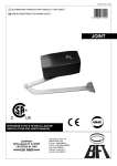
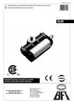
D811292 ver.02 14-02-03 I AUTOMAZIONI A BRACCIO PER CANCELLI A BATTENTE GB ARM AUTOMATIONS FOR SWING GATES 8 027908 171542 JOINT ISTRUZIONI D'USO E DI INSTALLAZIONE INSTALLATION AND USER'S MANUAL www.BFTGateOpeners.com | (800) 878-7829 USER’S MANUAL Thank you for buying this product. Our company is sure that you will be more than satisfied with the product’s performance. Carefully read the “WARNINGS” pamphlet and the “INSTRUCTION BOOKLET” which are supplied together with this product, since they provide important information regarding the safety, installation, use and maintenance of the product. This product complies with recognised technical standards and safety regulations. We declare that this product is in conformity with the following directives: CAN/CSA-C22.2 No. 247-92 UL Std. No. 325 (Certificate: 1002906 Date Issued: October 16, 2000). 1) GENERAL OUTLINE This controller is suitable for residential use and has been designed for swing gates with particularly large gate posts. The drive arm, built with a special anti-shearing shape, allows the leaves to be moved when the controller is considerably out of place with respect to the fulcrum of the leaves. The non-reversible electro-mechanical gearmotor maintains the stop during closing and opening. The release lever, fitted in each controller and situated inside the door fitted with personalised key, allows the manual manoeuvre to be easily carried out. WARNING! The installation, the maintenance and the repair should be done by responsible and qualified persons with an updated knowledge of the current safety standards. It’s strictly forbidden to service the automation when the power is on. ATTENTION! The JOINT model controller is not equipped with mechanical torque adjustment. It is compulsory to use a control panel of the same manufacturer, in compliance with the basic safety requirements equipped with appropriate electric adjusment of the torque. 2) EMERGENCY MANOEUVRE The emergency manoeuvre can be carried out form the inside by activating the appropriate lever on each controller, as in fig.1, and pushing the panel by hand. To restore motorised operation, turn the lever to its initial position and close the hatch having a personalised key. Fig. 1 4 - JOINT - Ver. 02 www.BFTGateOpeners.com | (800) 878-7829 D811292_02 ENGLISH INSTALLATION MANUAL Thank you for buying this product. Our company is sure that you will be more than satisfied with the product’s performance. Carefully read the “WARNINGS” pamphlet and the “INSTRUCTION BOOKLET” which are supplied together with this product, since they provide important information regarding the safety, installation, use and maintenance of the product. This product complies with recognised technical standards and safety regulations. We declare that this product is in conformity with the following directives: CAN/CSA-C22.2 No. 247-92 UL Std. No. 325 (Certificate: 1002906 Date Issued: October 16, 2000). 1) GENERAL SAFETY WARNING! An incorrect installation or improper use of the product can cause damage to persons, animals or things. • The “Warnings” leaflet and “Instruction booklet” supplied with this product should be read carefully as they provide important information about safety, installation, use and maintenance. • Scrap packing materials (plastic, cardboard, polystyrene etc) according to the provisions set out by current standards. Keep nylon or polystyrene bags out of children’s reach. • Keep the instructions together with the technical brochure for future reference. • This product was exclusively designed and manufactured for the use specified in the present documentation. Any other use not specified in this documentation could damage the product and be dangerous. • The Company declines all responsibility for any consequences resulting from improper use of the product, or use which is different from that expected and specified in the present documentation. • Do not install the product in explosive atmosphere. • The Company declines all responsibility for any consequences resulting from failure to observe Good Technical Practice when constructing closing structures (door, gates etc.), as well as from any deformation which might occur during use. • Disconnect the electrical power supply before carrying out any work on the installation. Also disconnect any buffer batteries, if fitted. • Fit an omnipolar or magnetothermal switch on the mains power supply, having a contact opening distance equal to or greater than 3mm. • Check that a differential switch with a 0.03A threshold is fitted just before the power supply mains. • Check that earthing is carried out correctly: connect all metal parts for closure (doors, gates etc.) and all system components provided with an earth terminal. • Fit all the safety devices (photocells, electric edges etc.) which are needed to protect the area from any danger caused by squashing, conveying and shearing, according to and in compliance with the applicable directives and technical standards. • Position at least one luminous signal indication device (blinker) where it can be easily seen, and fix a Warning sign to the structure. • The Company declines all responsibility with respect to the automation safety and correct operation when other manufacturers’ components are used. • Only use original parts for any maintenance or repair operation. • Do not modify the automation components, unless explicitly authorised by the company. • Instruct the product user about the control systems provided and the manual opening operation in case of emergency. • Do not allow persons or children to remain in the automation operation area. • Keep radio control or other control devices out of children’s reach, in order to avoid unintentional automation activation. • The user must avoid any attempt to carry out work or repair on the automation system, and always request the assistance of qualified personnel. • Anything which is not expressly provided for in the present instructions, is not allowed. INSTALL THE GATE OPERATOR ONLY WHEN: • The operator is appropriate for the construction of the gate and the usage Class of the gate. • All openings of horizontal slide gat are guarded or screened from the bottom of the gate to a minimun of 4 fet (1,2 m) above the fround to prevent a 2-1/4 inch (57,15 mm) diameter sphere from passing trough the openings anywhere in the gate, and in that portion of the adjacent fence the gate covers in the open position. • All exposed pinch points are eliminated or guarded. • Guarding i s supplied for exposed rollers. 8 - JOINT - Ver. 02 • • • The operator is intended for installation only on gates used for vehicles. Pedestrians must supplied with a separate access opening. The gate must be installed in a location so that enough clearance is supplied between the gate and adjacent structures when opening and closing to reduce the risk of entrapment. Swinging gates shall not open into public access areas. The gate must be properly installed and work freely in both directions prior to the installation of the gate operator. Do not over-tighten the operator clutch or presure relief valve to compensate for a damaged gate. FOR GATE OPERATOR WITH HOLD-TO-RUN CONTROL: • The gate operator controls must be placed so that the user has full view of the gate area when the gate is moving, • A sign with the message “WARNING” must be positioned near the controls. The characters for the writing should be at least 6.4 mm high. The following statement should also be indicated: “Moving Gate Has the Potential of Inflicting Injury or Death - Do Not Start Gate Unless Path is Clear” • An automatic closing device (such as a timer, loop sensor, or similare device) shall not be employed. • No other activation device shall be connected. Controls must be far enough from the gate so that the user is prevented from coming in contact with the gate while operating the controls. controls intended to be used to reset an operator after 2 sequential activations of the entrapment protection device or devices must be located in the line-of-sight of the gate. Outdoor or easly accesible controls shall have a security feature to prevent unauthorized use. All warnings signs and placards must be installed where visible in the area of the gate. FOR GATE OPERATOR PROVIDED WITH SENSOR FOR CONTACTFREE DETECTION: • • • See instructions on the placement of non contact sensor for each type of application, Care shall be exercised to reduce the risk of nuisance tripping, such as when a vheicle, trips the sensor while the gate is still moving, and One or more non-contact sensor shall be located where the risk of entrapment or obstruction exist, such as the perimeter reachable by a moving gate or barrier. FOR GATE OPERATOR PROVIDED WITH CONTACT DETECTION (RUBBER SKIRT OR SIMILAR): • On or more contact sensor shall be located at the pinch point of a vehicular vertical pivot gate. • A hardwired contact sensor shall be located and its wiring arranged so that the communication between the sensor and the gate operator is not subjected to mechanical damage. • A wireless contact sensor such as one that transimts radio frequency (RF) signals the gate operator for entrapment protection functions shall be located where the transimission of the signals are not obscrtucted or impeded y building structure, natural landscaping or similar obstruction. A wireless contact sensor shall function under the intended end-use conditions. IMPORTANT SAFETY INSTRUCTIONS WARNINGS: to reduce the risk of injury or death: • Read and follow all instructions. • Never let children operate or play with gate control. Keep the remote control away from children. • Always keep people and objects away from the gate. NO ONE SHOULD CROSS THE PATH OF THE MOVING GATE. • Test the gate operator montly. The gate MUST reverse on contact with a rigid object activates the non-contact sensor. After adjusting the force or the limit of travel, reset the gate operator. Failure to adjust and retest the gate operator properly can increase the risk of injury or death. • Use the emergency realease only when the gate is not moving. • KEEP GATES PROPERLY MAINTAINED. Read the owners manual. Have a qualified service person make repairs to gate hardware. • The entrance is for veichles only. Pedestrians must use separate entrance. • Save these instructions. www.BFTGateOpeners.com | (800) 878-7829 D811292_02 ENGLISH D811292_02 INSTALLATION MANUAL 2) GENERAL OUTLINE This controller is suitable for residential use and has been designed for swing gates with particularly large gate posts. The drive arm, built with a special anti-shearing shape, allows the leaves to be moved when the controller is considerably out of place with respect to the fulcrum of the leaves. The non-reversible electro-mechanical gearmotor maintains the stop during closing and opening. The release lever, fitted in each controller and situated inside the door fitted with personalised key, allows the manual manoeuvre to be easily carried out. WARNING! The installation, the maintenance and the repair should be done by responsible and qualified persons with an updated knowledge of the current safety standards. It’s strictly forbidden to service the automation when the power is on. ATTENTION! The JOINT model controller is not equipped with mechanical torque adjustment. It is compulsory to use a control panel of the same manufacturer, in compliance with the basic safety requirements of directives 73/23/CEE, 89/336/CEE, 89/37/CEE equipped with appropriate electric adjusment of the torque. 3) TECHNICAL SPECIFICATIONS Voltage: ....................................................................... 120V±10% 50Hz (*) Motor: .................................................................... Single-phase 1400min-1 Power: ................................................................................................ 300W Absorption: ........................................................ 1.7A (230V); 3,4A (120V) Capacitor: ..................................... 10µF 450V (230V); 40µF 250V (120V) Insulation class: ........................................................................................ F Thermal protection: ........................... 266°F ........... (130°C) self-resetting Lubrication: ................................................................... Permanent grease Reduction ratio: ................................................................................. 1/812 Output revs.: .......................................................................... 1.7 min-1max Output shaft: ................................................................. 20x20 hollow shaft Opening time 90°: ................................................................................. 15s Torque provided: ................. 320Nm (~32kgm)........236.01lbf/ft (~70.54lb) Max. leaf weight and length: for 2.5m leaf length ................ 2000N (~200kg)........449.61 lbf (~440.92lb) for 2m leaf length ................... 2500N (~250kg).........562.02lbf (~551.15lb) Impact reaction: ................................... Electric clutch (with control panel) Drive: .......................................................................................... Lever arm Stopping: ...................................................... Built-in electric limit-switches Manual manoeuvre: ........................................ Door with personalised key Number of manoeuvres: ................................................................ 100/24h Working temperature: ................... -15 ÷ +60 C..........................°59÷140°F Protection: ......................................................................................... IP 44 Controller weight: ....... 160N (~16kg) 35.96 lbf .........................(~35.27 lb) Dimensions: .................................................................................. See fig.1 *Special supply voltages on request buckle “M” of the operator. Refer to the relevant instruction manual for connection of the control panel. 4) INSTALLATION OF AUTOMATION Preliminary checks Check: - That the structure of the gate is rigid and strong enough. The fixing position should be assessed according to the structure of the leaf. In any case, the manoeuvring arm must push against a reinforced point in the leaf (fig.2). - That the leaves move manually for the whole of their stroke. If a new gate is not being installed, check whether its components are worn. Repair or replace any worn or damaged parts. Automation reliability and safety are directly influenced by the condition of the gate’s structure. 5) FIXING OF SUPPORTING PLATE (Fig.2) The controller is supplied complete with anchoring bracket and lever arm. Once the reinforcement point of the leaf has been identified with the gate closed, draw an imaginary horizontal line from the centre of the reinforcement point to the gate post (fig.2). Position the anchoring bracket according to the values given in fig. 2 for openings of up to 90° or in fig.3 for openings greater than 90° up to a maximum of 125°. The bracket fixing position must be flat and parallel to the leaf. Use screws or expansion bolts which are suited to the type of gate post. If the surface of the gate post is not regular, use expansion bolts with studs so that the parallel plate of the leaf can be adjusted (fig.4). - Fasten the gearmotor to the gate post using the 4 screws, pointing the gearmotor to the left or the right (fig.5). - Assemble the lever arm as shown in fig.6. DX= assembly on the right leaf SX= assemby on the left leaf Choose the most suitable position of ‘F’ bracket for the fastening to the leaf. - Insert the square of the first lever in the output shaft of the gearmotor and - - ENGLISH fasten it (fig.7). Release the controller by activating the release lever so that the arm can move easily (see the “EMERGENCY MANOEUVRE” paragraph). The correct position for the controller arm is shown in fig.8. The leaf fixing point “A” can be identified by positioning the arm so that it is in accordance with the distance shown in fig.8. Fix the angular towing bar “A” to the leaf by welding or using screws. With the controller released, check the correct movement of the arm. Repeat the same operation for the other leaf, if installed. 6) ELECTRICAL INSTALLATION SET-UP Arrange the electrical installation as shown in fig.9. The power supply connections must be kept separate from the auxiliary connections (photocells, sensitive edge, etc.). Fig.9 shows the crosssection and the number of connections. CAUTION! Connection to the mains must be carried out using the type of multipolar cable specified in the standards (UL1015). In fig.10 you will find the junction-box of the operator and the position of the cable holder which should be fixed with an adequate tightening of the bolt. In case the motor tours in the opposite side, you should invert the running buckle "M" of the operator. Refer to the relevant instruction manual for connection of the control panel. 7) LIMIT SWITCH ADJUSTMENT - Remove the casing of the limit switches. - Identify the limit switches following fig.12 for the right-hand controller and following fig.11 for the left-hand controller. - Adjust the opening and closing cams respectively with the gate completely open and completely closed. - Turn the identified cam until the intercepting limiting microswitch triggers and lock the cam in position by tightening the screw. - Make sure that limit switch intervention is correct and refit the cover which was previously removed. - Fit the casing. - If the control unit has working time adjustment (TW), this should be adjusted to a value which is slightly higher than the intervention of the controller limit switches. 8) ADJUSTMENT OF LEAF PHASE DISPLACEMENT In case of gates with two leaves, the control panel should include a delay setting function on closing of the second leaf to guarantee a correct closing manoeuvre. For the wiring of the motor which should close with a slight delay, refer to the instructions for the control panel installed. 9) MOTOR TORQUE ADJUSTMENT The adjustment of the motor torque (anti-squashing) is performed on the control panel. See control unit instruction manual. The adjustment should be set for the minimum force required to carry out the opening and closing strokes completely observing, however, the limits of the relevant standards in force. CAUTION! Excessive torque adjustment may jeopardise the anti-squash safety function. On the other hand insufficient torque adjustment may not guarantee correct opening or closing strokes. 10) EMERGENCY MANOEUVRE The emergency manoeuvre can be carried out form the inside by activating the appropriate lever on each controller, as in fig.13, and pushing the panel by hand. To restore motorised operation, turn the lever to its initial position and close the hatch having a personalised key. 11) AUTOMATION CHECK Before allowing the automation to be used normally, carry out the following procedure very carefully: - Check the correct functioning of all safety devices (limit microswitches, photocells, sensitive edges etc.). - Check that the thrust (anti-squash) force of the leaf is within the limits set by current regulations. - Check the manual opening command. - Check the opening and closing operations with the control devices in use. - Check the standard and customised electronic functioning logic. 12) AUTOMATION OPERATION Since the automation can be remote-controlled by means of a remote control device or a start button, and so out of sight, the good working order of all the safety devices should be checked regularly. In the event of any anomalous functioning of the safety devices, consult a specialised technician immediately. Keep children at a safe distance from the automation operation area. www.BFTGateOpeners.com | (800) 878-7829 JOINT - Ver. 02 - 9 INSTALLATION MANUAL 13) CONTROL The automation is used for the power-operated opening and closing of the gate. The control can be of a number of types (manual, remote-controlled, magnetic badge access control, etc.) depending on requirements and the characteristics of the installation. See the specific instructions for the various control systems. Users of the automation must be instructed about its control and operation. 14) MAINTENANCE Disconnect the power supply when carrying out any maintenance operations. - Lubricate the joints of the manoeuvring arm regularly. - Clean the lenses of the photocells every so often. - Have a specialised technician (installer) check the adjustment of the electric clutch. - In the event of any anomalous functioning which cannot be resolved, disconnect the power supply and contact a specialised technician (installer). Whilst the automation is out of order, activate the manual release to allow manual opening and closing. 15) SCRAPPING WARNING! This operation should only be carried out by qualified personnel. Materials must be disposed of in conformity with the current regulations. In case of scrapping, the automation devices do not entail any particular risks or danger. In case of materials to be recycled, these should be sorted out by type (electrical components, copper, aluminium, plastic etc.). 16) DISMANTLING WARNING! This operation should only be carried out by qualified personnel. When the automation system is disassembled to be reassembled on another site, proceed as follows: - Disconnect the power supply and the entire external electrical installation. - In the case where some of the components cannot be removed or are damaged, they must be replaced. The descriptions and illustrations contained in the present manual are not binding. The Company reserves the right to make any alterations deemed appropriate for the technical, manufacturing and commercial improvement of the product, while leaving the essential product features unchanged, at any time and without undertaking to update the present publication. 10 - JOINT - Ver. 02 www.BFTGateOpeners.com | (800) 878-7829 D811292_02 ENGLISH D811292_02 Fig. 2 Fig. 3 6.18" (157) Fig. 1 3.11" (79) 11.81" max 4.33" (110) 23.62" (600) 122.46" (110) SX 12.40" (315) min 12.40" (315) min 93ß 6.69" (170) 0.78" (20) 5.13" (135) 6.69" (170) (300 max) 7.04" (179) SX 13.70" (348) 3.93" (100) 5.13" (135) 2.75" (70) 10.94" (278) 90ß 180ß 180ß 125ß 125ß 6.69" (170) 27.55" (700) The values between brackets are expressed in millimetres Fig. 4 Fig. 5 SX Fig. 6 DX Fig. 7 S F Fig. 8 DX SX S ) 015 6" (1 39.3 S S www.BFTGateOpeners.com | (800) 878-7829 JOINT - Ver. 02 - 11 D811292_02 Fig. 9 18 AWG = 1 mm2 16 AWG = 1.5 mm2 AL M S Fre G AW 16 WG 4x A 18 2x 3x1 G AW 8AW 18 4x Fti G RG 58 Fte Q R 2x1 6A CF 2x1 WG 8A WG I 3x1 M 6A WG WG A 6 x1 4 T Fri G AW 18 4x CF Fig. 10 3 2 F1 F2 1 GND F1 F2 L M 230V CM N 12 - JOINT - Ver. 02 M 1 2 3 F2-NC F2-COM F1-NC F1-COM NERO-BLACK MARRONE-BROW CELESTE-SKY www.BFTGateOpeners.com | (800) 878-7829 M D811292_02 Fig. 11 R - FC2 R - FC1 R - FC1 R - FC2 FC1 FC1 FC1 FC2 FC2 FC2 Fig. 12 Fig. 13 RIGHT LEFT SX (LEFT) DX (RIGHT) OPEN SX FC1 CLOSE DX FC1 CLOSE SX FC2 OPEN DX FC2 Fig. 14 www.BFTGateOpeners.com | (800) 878-7829 JOINT - Ver. 02 - 13