1
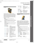
MODEL PS-31
Power Supply
User Manual
PROGRAM
CHANNEL STATUS
ON
1
2
3
RTS SYSTEMS
TW INTERCOM SYSTEM
POWER SUPPLY
PS31
CHANNEL
ASSIGN
9300-4437-00 Rev J
FAULT
1
2
THERMAL
OVERLOAD
3
POWER
LEVEL
AUDIBLE
ALERT
12/2007
PROPRIETARY NOTICE
The product information and design disclosed herein were originated by
and are the property of Telex Communications, Inc. Telex reserves all
patent, proprietary design, manufacturing, reproduction, use and sales
rights thereto, and to any article disclosed therein, except to the extent
rights are expressly granted to others.
COPYRIGHT NOTICE
Copyright 2007 by Telex Communications, Inc. All rights reserved.
Reproduction, in whole or in part, without prior written permission from
Telex is prohibited.
WARRANTY NOTICE
SHIPPING TO THE MANUFACTURER
All shipments of product should be made via UPS Ground, prepaid (you
may request from Factory Service a different shipment method). Any
shipment upgrades will be paid by the customer. The equipment should
be shipped in the original packing carton. If the original carton is not
available, use any suitable container that is rigid and of adequate size. If
a substitute container is used, the equipment should be wrapped in paper
and surrounded with at least four (4) inches of excelsior or similar
shock-absorbing material. All shipments must be sent to the following
address and must include the Proof of Purchase for warranty repair.
Upon completion of any repair the equipment will be returned via
United Parcel Service or specified shipper, collect.
CUSTOMER SUPPORT
Factory Service Department
Telex Communications, Inc.
8601 East Cornhusker Hwy.
Lincoln, NE 68507 U.S.A.
Attn: Service
Technical questions should be directed to:
This package should include the following:
See the enclosed warranty card for further details.
Customer Service Department
RTS/Telex Communications, Inc.
12000 Portland Avenue South
Burnsville, MN 55337 USA
Telephone: 800-392-3497
Fax: 800-323-0498
RETURN SHIPPING INSTRUCTIONS
Customer Service Department
Telex Communications, Inc. (Lincoln, NE)
Telephone: 402-467-5321
Fax: 402-467-3279
Factory Service: 800-553-5992
Please include a note in the box which supplies the company name,
address, phone number, a person to contact regarding the repair, the type
and quantity of equipment, a description of the problem and the serial
number(s).
Table
of
Contents
DESCRIPTION ................................................. 1
MAINTENANCE ............................................. 11
DESCRIPTION .......................................................1
INTRODUCTION .................................................11
GENERAL MAINTENANCE ................................11
GENERAL ...................................................................1
FEATURES .................................................................1
STATUS INDICATORS ....................................................2
INPUT POWER ..............................................................2
INTERCOM CHANNEL CONNECTIONS ..........................2
IMPEDANCE SELECTION ..............................................2
SAFETY CONSIDERATIONS .................................. 11
ACCESS .................................................................... 11
CLEANING ............................................................... 11
INPUT POWER SELECTION .................................. 12
CHANNEL DC OUTPUT FUSE REPLACEMENT . 12
Installation ..............................................................3
TEST PROCEDURES ...........................................12
MECHANICAL INSTALLATION ................................3
ELECTRICAL INSTALLATION ..................................3
TEST EQUIPMENT .................................................. 12
INITIAL INSPECTION ............................................. 12
POWER-UP TEST .................................................... 12
POWERED CHANNEL TEST .................................. 13
FUNCTIONAL TEST OF ALL OUTPUTS ............... 14
4.4 TROUBLESHOOTING ....................................... 15
OPERATION ..................................................... 5
POWER-UP INDICATIONS ...................................5
FAULT INDICATIONS ...........................................5
THERMAL OVERLOAD .........................................5
IMPEDANCE SELECT SWITCHES .......................5
PROGRAM INPUT .................................................5
THEORY OF OPERATION ............................. 7
GENERAL ...............................................................7
AC TO DC CONVERSION .....................................7
IMPEDANCE GENERATOR ..................................7
PROGRAM INSERTION AMPLIFIER ...................8
DISPLAY AND DIAGNOSTIC CIRCUITRY ..........8
CHANNEL STATUS INDICATORS ............................8
FAULT INDICATOR ...................................................8
THERMAL OVERLOAD .............................................8
REPLACEMENT PARTS ............................... 17
WHERE TO OBTAIN PARTS ...............................17
MECHANICAL PARTS .......................................18
ELECTRICAL PARTS .........................................19
DIAGRAMS AND SPECIFICATIONS .......... 25
Specifications ........................................................33
CHAPTER 1
DESCRIPTION
DESCRIPTION
GENERAL
The Model PS31 supplies 32 volts regulated DC power to each of three intercom channels. It has short circuit and thermal
overload protection, with automatic recovery when the fault is removed.
FEATURES
Program Input
There is a PROGRAM INPUT connector on the rear panel. A CHANNEL ASSIGN switch on the front panel assigns the
program to any of the three channels. A LEVEL control adjusts the program level to the intercom channel.
1
PROGRAM
CHANNEL STATUS
ON
1
2
3
RTS SYSTEMS
TW INTERCOM SYSTEM
POWER SUPPLY
PS31
2
THERMAL
OVERLOAD
3
POWER
LEVEL
AUDIBLE
CHANNEL
ASSIGN
ALERT
TELEX COMMUNICATIONS, INC.
MADE IN USA
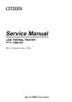
CONNECTOR
PIN-OUT CODE
CH 1 - 2
PIN - 1 COM
PIN - 2 CH 1
PIN - 3 CH 2
CH 2 - 3
CH 1 - 2 - 3
CH 1 - 3
PIN - 1 COM PIN - 1 COM PIN - 1 CH 1
PIN - 2 CH 1 PIN - 2 CH 2 PIN - 2 CH 2
PIN - 3 CH 3 PIN - 3 CH 3 PIN - 3 CH 3
PIN - 4 COM
TW INTERCOM SYSTEM
POWER SUPPLY
MODEL PS 31
J111
NOTE
INTERNALLY
FUSED
1
FAULT
OUTPUTS CONNECT TO
TW INTERCOM SYSTEM COMPONENTS
REFER TO OPERATION MANUAL
PROGRAM INPUT
Z = 10K BALANCED
PIN 1 - GROUNDED
PIN 2 - LO
PIN 3 - HI
OUTPUTS
CH 1-2
CH 1-2
CH 1-3
CH 1-3
CH 2-3
CH 2-3
J101
J102
J103
J104
J105
J106
CH 1-2-3
CH 1-2-3
CH 1-2-3
PUSH
IMPEDANCE SELECT
CHANNEL
1
AC POWER
CAUTION - TO REDUCE THE RISK OF FIRE, REPLACE ONLY WITH SAME TYPE FUSE
WARNING - TO REDUCE THE RISK OF FIRE OR ELECTRIC SHOCK, DO NOT EXPOSE THIS APPLIANCE TO RAIN OR MOISTURE
FIGURE 1.
J107
J108
J109
2
3
400 W
DUAL
200 W
NORM
J110
PS-31 Front and Back View
Status Indicators
There is an audible alarm and a red FAULT indicator for current overload indication on any of the three channels. An
AUDIBLE ALERT switch on the front panel turns the alarm on or off, but the FAULT indicator will continue to flash during
current overload conditions. There is also a green status indicator for each channel. Each of these indicators will remain lit
during normal operation, but will turn off during a channel current overload condition. Output current is automatically reduced
during an overload, and normal operation is restored when the overload is removed.
Input Power
The PS31 is available in two versions: one for 115 VAC operation and one for 230 VAC operation. A simple internal
modification changes the operating voltage for 100 VAC or 200 VAC. A POWER on/off switch is provided on the front panel.
Intercom Channel Connections
Intercom channels are connected to the rear panel of the PS31. A variety of connector pin-outs is provided to accommodate
individual system requirements.
Impedance Selection
The PS31 provides the required channel terminating impedance for each channel. A 200/400 ohm IMPEDANCE SELECT
switch for each channel is located on the rear panel. These switches are set to 200 ohms for normal operation. The 400 ohm
setting permits two PS31's to be coupled to double the DC capacity of the system.
2
Installation
MECHANICAL INSTALLATION
The Model PS31 can be rack mounted or used free standing. The rack mount is a standard 19-inches wide by 3.5-inches high.
Allow room for cable connections.
ELECTRICAL INSTALLATION
CONNECTING INTERCOM STATIONS
NOTE:
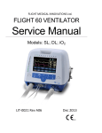
When connecting intercom stations, do not exceed the power supply capacity, either for one channel or for all
three channels. Power supply capacity is graphically illustrated in Figure 1. If more capacity is required, refer to
“PS 31 Capacity” on page 4.
Connect intercom channels to the OUTPUTS connectors on the rear panel. Pin assignments are printed above the connectors.
These connectors provide three alternatives for intercom channel connection:
•
•
•
Connectors J101 through J106 can be used to connect various combinations of two channels.
Connectors J107 and J108 can be used to connect all three channels.
Connector J109 can also be used to connect three channels, but unlike all the other connectors, no power is
supplied at this connector. This connector can be used to interconnect the audio channels when using two PS31
power supplies.
USING TWO PS31'S TO EXPAND CAPACITY
If there are more stations on one or more channels than the power supply capacity will allow, two PS31 power supplies may be
used to double capacity. For each channel that requires added capacity:
1.
Use the J109 connectors on both power supplies to interconnect the audio and ground pins of the desired channel (See
“PS-31 Front and Back View” on page 2.).
2.
Divide the stations that you wish to connect into two groups. Connect one group to the first power supply. Connect
the other group to the second power supply. For each group, do not exceed the capacity (either total or per channel) of
the power supply.
3.
On both power supplies, set the IMPEDANCE SELECT switches for the channel to the 400<F128M>W<F255D>
DUAL position. (Leave all impedance switches for channels that are not interconnected in the
200<F128M>W<F255D> NORM position.
PROGRAM INPUTS
A program source may be connected to the PROGRAM INPUT connector on the rear panel. Pin assignments are printed above
the connector (See “PS-31 Front and Back View” on page 2.).
To connect an unbalanced program source, connect pin 2 to to pin 1. Then connect program ground to pin 1 and program HI to
pin 3.
If two PS31's are interconnected, a separate program source may be connected to each.
AC POWER
Plug the AC power cord into the PS31 and into an AC mains outlet.
3
NOTE:
The PS31 is factory-set for either 110-120-volt operation or 220-240-volt operation. The operating voltage is
indicated on the back of the unit. Operation at 100-110 volts or 200-220 volts requires an internal modification.
Refer to “MAINTENANCE” on page 11.
FIGURE 2.
4
PS 31 Capacity
CHAPTER 2
OPERATION
POWER-UP INDICATIONS
Turn on the POWER switch. During normal operation the three CHANNEL STATUS indicators should be lit and the FAULT
and THERMAL OVERLOAD indicators should be off.
FAULT INDICATIONS
If there is a fault on a channel, the CHANNEL STATUS indicator for that channel will turn off and the red FAULT indicator
will flash. If the AUDIBLE ALERT is set to “ON”, the alarm will beep. Possible causes of a fault include: overvoltage,
overcurrent, short circuit to ground or severe brown-outs.
THERMAL OVERLOAD
If the PS31 overheats, the THERMAL OVERLOAD indicator will turn on and AC power to the PS31 will be shut off. Normal
operation will resume when the PS31 cools. Possible causes of a thermal shut-down include overloading the output channels
or improper internal mains voltage selection.
IMPEDANCE SELECT SWITCHES
The IMPEDANCE SELECT switches on the rear panel allow each channel to be set for 200 ohm or 400 ohm operation. Select
200<F128M>W<F255D> NORM for each channel operated independently. Select 400<F128M>W<F255D> DUAL for each
channel connected to another channel through the AUDIO ONLY connector (J109). Figure 1, “PS-31 Front and Back View,”
on page 2
PROGRAM INPUT
If a program source is connected to the PROGRAM INPUT connector on the back of the PS31, it may be routed to any one of
the intercom channels using the CHANNEL ASSIGN switch. Use the LEVEL control to adjust the program level on the
selected channel.
5
6
CHAPTER 3
THEORY OF OPERATION
GENERAL
The PS31 electronic circuits include an AC to DC converter, an impedance generator for each channel, a program insertion
amplifier, and display and diagnostics circuits (Figure 3 on page 9). The following paragraphs describe these circuits. For
schematic reference, see drawing SD3225 in Chapter 7.
AC TO DC CONVERSION
Transformer T101 steps down the AC mains voltage to 33 volts rms. Diodes D101-D104 rectify this voltage and capacitor
C117 filters out the AC component, leaving about 45-50 volts unregulated DC. This raw DC voltage feeds the impedance
generators (through fuses F201, F301, and F401), and regulator U101.
U101 provides regulated 30 volts DC. This voltage is supplied to the impedance generators, to the program insertion amplifier,
and to U102. Diodes D109 and D110 protect U101. Resistors R107 and R108 establish the output voltage reference of 30 volts
DC. Capacitor C121 reduces the amount of ripple on the 30 volts DC, and C122 provides decoupling.
U102 provides regulated 7.5 volts DC. This voltage is used as a reference level by the program insertion amplifier. It also
powers the display circuits. Diodes D111 and D112 protect U102. Resistors R109 and R110 establish the output voltage
reference of 7.5 volts. Capacitor C123 reduces the amount of ripple on the 7.5 volts DC and C124 filters the output.
IMPEDANCE GENERATOR
There is a separate impedance generator for each channel. The impedance generator supplies regulated 32 volts DC to the
channel and also provides the channel terminating impedance. The following paragraphs describe the impedance generator for
channel 1. Other channels are identical.
Diodes D202 and D201 and resistors R202 and R201 divide the raw DC for the variable DC reference. This variable DC
reference allows the quiescent output voltage of the regulators to follow the rms value of the AC mains voltage. Capacitors
C202, C203 and C204 and resistors R203 and R206 are a low pass filter for the variable DC reference and provide fast start up
response time. Integrated circuit U202B, resistors R214, R215 and R217 and capacitors C210 and C207 amplify and buffer the
variable DC reference. Resistor R213 and capacitor C209 decouple the supply voltage for integrated circuit U202. Resistors
R211 and R208 set the amount by which the output voltage of the regulator exceeds the variable DC reference. R205 sinks the
quiescent current from R208. Diode D203 clamps excessive output voltage of the regulator due to transients while diodes
D204 and D206 protect the regulator from reversed voltages due to shorts on the output line.
7
Resistors R219 and R221 sense the output current from the regulators into the RTS line. Integrated circuit U202A, together
with capacitors C212 and C214 and resistors R220, R225, R223, and R216 differentially amplify this output current and feed
it back to the adjust terminal of the regulators to create the audio impedance. Diodes D207, D208, D211, D212, D209, and
D210 clamp the audio output voltage to avoid over-driving the RTS line and allow fast recovery from large transients.
Diode D214 protects the impedance generator from an over voltage on the RTS line. Capacitor C215 is an RF bypass and
resistor R227 biases diode D214 on with 10 mA of current for “dry line” operation. Toggle switch S201, located on the rear
panel selects an output impedance of 200 or 400 ohms. Since the impedance generator operates at 400 ohms, toggle switch
S201 shunts the output with 390 ohms for a 200 ohm output.
PROGRAM INSERTION AMPLIFIER
The program-insertion amplifier circuitry accepts balanced or unbalanced input from any source and injects this input, via a
bilateral current source, onto the RTS line.
Program audio, present at connector J110, rear panel, is applied via input isolation transformer T103 to PROGRAM LEVEL
potentiometer R111. Resistor R606 and capacitor C601 provide RF suppression. Integrated circuit U601a, capacitor C602 and
resistors R603 and R602 amplify the input and provide a low impedance drive for the following stage. Integrated circuit
U601b, capacitor C606 and resistors R604, R607, R609, R605, and R608 form the bilateral current source which turns the
input voltage into an output current. Capacitors C604, C605 and resistor R610 blocks any DC potential on the RTS line.
Diodes D601 and D602 protect integrated circuit U601 from transients and resistor R601 and capacitor C603 decouple the
power to integrated circuit U601.
DISPLAY AND DIAGNOSTIC CIRCUITRY
The display and diagnostic circuits detect fault conditions and warn the user with front panel lights and an audio indicator.
CHANNEL STATUS INDICATORS
(The channel status indicator for channel is described. The channel status indicators for channels 2 and 3 are identical.)
As long as the output voltage on channel 1 is above approximately 21 VDC, diode D205 will conduct causing transistor Q201
to be on, which turns on DS201, the CHANNEL 1 STATUS LED on the front panel. If the channel 1 voltage drops below
approximately 21 volts, transistor Q201 shuts off, LED DS201 goes dark, and the fault indicator circuitry is notified through
diode D215.
FAULT INDICATOR
If pin 5 of integrated circuit U103 is driven high by an under-voltage condition on any channel, the flasher circuit, which
consists of half of integrated circuit U103, capacitor C126 and resistors R116 and R117, will flash the FAULT indicator LED,
DS101, and pulse the audible alarm circuit. The audible alarm oscillator consists of the other half of integrated circuit U103,
capacitor C127 and resistors R120 and R121.
THERMAL OVERLOAD
Switch S101 is a thermal sensing switch connected in series with the power switch. It is attached to the power transformer,
T101. The front panel THERMAL OVERLOAD indicator, DS5, is connected across S101. If the transformer temperature
remains below approximately 75 C, S101 will remain closed, and there will be no voltage drop across DS5. If the transformer
temperature rises above 75 C, S101 will open and remove AC primary power to T101. The AC voltage will be developed
across DS5 and it will light.
8
FIGURE 3.
Block Diagram
9
10
CHAPTER 4
MAINTENANCE
INTRODUCTION
This section provides service information for normal maintenance, factory performance tests and troubleshooting tips.
GENERAL MAINTENANCE
SAFETY CONSIDERATIONS
Service and adjustments should be performed only by qualified service personnel.
Any adjustment, maintenance, and repair of the opened equipment while any power or voltage is applied should be avoided as
much as possible, and should be carried out only by a skilled person who is aware of the hazard involved.
It is possible for capacitors inside the equipment to still be charged even if the equipment has been disconnected from its
power source.
Be certain that only fuses with the required current rating and of the specified type (fast blow, time delay, slow blow, etc.) are
used for replacement. The use of repaired fuses and the short-circuiting of fuse holders must be avoided.
ACCESS
To get inside the Model PS31, remove the screws on the top and bottom covers. Slide covers off toward the back of the unit.
CLEANING
Clean the outside of the Model PS31 with denatured alcohol or a mild solution of detergent and water. Clean the interior with
dry, low pressure air. The circuit boards can be cleaned with 1,1,1 trichloroethane or Freon TF. Do not allow these or any
solvents to get into any potentiometers.
11
INPUT POWER SELECTION
CAUTION: These maintenance instructions are for qualified personnel only. To avoid electric shock, do not perform any
servicing unless qualified to do so. Disconnect AC power before servicing.The Model PS31 operates on 100,
120, 200, or 240 volts AC at 50/60 hertz, depending on the internal power settings. To convert from one mains
voltage to another, remove the covers and set the internal switch, jumpers and use the proper rear panel fuse as
specified in Table 3. (The switch and jumpers are located on the circuit board next to the power transformer
connector.)
TABLE 1. Voltage
Selection
S107
Setting
AC Source
Jumpers
Add
Remove
Rear
Panel
Fuse
100 VAC
115
W2, W3
W1, W4
3A
120 VAC
115
W1, W4
W2, W3
3A
200 VAC
230
W2, W3
W1, W4
1.5A
240 VAC
230
W1, W4
W2, W3
1.5A
CHANNEL DC OUTPUT FUSE REPLACEMENT
To replace channel fuses (F201, F301, F401), remove covers. These fuses are located on the circuit board.
TEST PROCEDURES
TEST EQUIPMENT
•
An isolated, variable voltage power transformer with voltage and current metering ("VARIAC",
"POWERSTAT", or equivalent)
•
•
•
•
•
•
•
•
•
A sine wave oscillator
An oscilloscope, 15 megahertz minimum bandwidth
A distortion analyzer (HP331 through HP334, HP339, or equivalent)
An AC voltmeter capable of reading volts, dBm and dBu
Two DC voltmeters
A test load (see Figure 4)
A capacitive load box (see Figure 5)
A program input cable (see Figure 6)
Two channel output cables (see Figure 7)
INITIAL INSPECTION
Verify electrical orientation of power supply capacitors. Verify proper wiring of transformer primary for local mains voltage.
Verify that the proper fuses are installed in the back panel fuse holder and on the printed circuit board. Check that the
transformer is securely mounted and that it is electrically isolated from the chassis (resistance from chassis to transformer core
should be greater than 10 kohms). Check that the power supply capacitor is securely fastened. Using an ohmmeter, verify that
the chassis is electrically connected to the grounding pin on the power connector (less than 0.2 ohm).
POWER-UP TEST
1.
12
Set the variable voltage power transformer to off, and set the voltage to zero.
2.
Plug the PS31 into the variable voltage power transformer.
3.
Set the PS31 POWER switch to ON.
4.
Set the PS31 AUDIBLE ALERT switch to ON.
5.
Turn on the variable voltage power transformer.
6.
Slowly turn up the voltage. Watch for excessive sustained current consumption above 1 ampere. While the voltage is
being increased, the audible alert indicator should sound and the FAULT light should flash. Stop increasing the
voltage when the standard operating voltage level is reached.
7.
Set the AUDIBLE ALERT switch to off.
8.
Turn the PS31 POWER switch off: the STATUS lights should fade, and finally, the FAULT light should blink. The
audible alert should not sound.
9.
Turn the POWER switch back on.
10.
Turn the AUDIBLE ALERT switch on.
POWERED CHANNEL TEST
The following procedure tests channel 1. Repeat for channels 2 and 3.
1.
Connect the DC meters and capacitive load to the test load as shown in Figure 5-1.
2.
Set the capacitive load to OFF.
3.
On the test load, set the output current potentiometer in the fully CCW position (minimum output load).
4.
Plug one of the four-wire channel output cables into J108 on the PS31. This will be the powered output cable
5.
Connect the ground lead of the powered output cable to the test load ground terminal.
6.
Connect channel 1 of the powered output cable to the powered channel terminal of the test load.
7.
Connect the second four-wire output cable to J109 on the PS31. This will be the AUDIO ONLY output cable.
8.
Connect channel 1 and ground of the audio only output cable to the distortion analyzer input and to the AC voltmeter.
9.
Connect the program input cable to the PS31 PROGRAM INPUT (J110) and to the sine wave oscillator.
10.
On the PS31, set the PROGRAM CHANNEL ASSIGN switch to channel 1. Turn the PS31 PROGRAM LEVEL
control fully CCW (minimum level).
11.
Set the sine wave oscillator for 1 kilohertz, 0.10 volt rms at the PROGRAM INPUT of the PS31.
12.
Observe the DC output voltage on DC voltmeter 1. It should be between 31.0 and 32.5 volts DC.
13.
Set the output current adjustment control on the test load so that the output current is 0.50 amperes (0.5 volts at DC
voltmeter 2). The output voltage at voltmeter 1 should drop by 0.5 volts or less.
14.
Adjust the PS31 PROGRAM LEVEL control fully CW (maximum level). The AC voltage should be 1.8 volts rms.
15.
Adjust the PROGRAM LEVEL control until the AC voltmeter reads 1.0 volt rms. The waveform on the scope should
be a sine wave with no hum or distortion.
16.
Set the capacitive load box switch to 100 pF. The waveform on the scope should remain unaffected. Repeat this step
for all the positions of the switch. The only noticeable effect should be waveform attenuation with the higher
capacitance values.
17.
Set the capacitive load to OFF.
18.
Set the oscillator frequency to 10 kilohertz (the oscillator level should remain constant). The AC voltage should read
between 0.79 and 1.0 volts rms.
19.
Set the oscillator frequency to 100 hertz (the oscillator level should remain constant). The AC voltage should read
between 0.71 and 0.89 volts rms. Return the oscillator frequency to 1 kilohertz.
20.
Place a 200-ohm resistor across the distortion analyzer input. The AC voltmeter should read from 0.45 to 0.55 volts
rms. Remove the 200-ohm resistor.
21.
Short the POWERED CHANNEL terminal of the test load to the SHORTING TERMINAL on the test load. The
output short circuit current should be 0.5 amp (0.5 volts at DC voltmeter 2), 30%. The channel 1 STATUS light
should be extinguished, the FAULT light should be flashing, and the audible alert should sound. Remove the short.
The FAULT light should go out and the channel 1 STATUS light should turn on.
13
22.
On the test load, slowly turn the output current adjustment control CW. The output current (as measured at DC
voltmeter 2) should slowly increase. The FAULT light and audible alert should again come on as the output voltage
drops below approximately 21 volts (measured at DC voltmeter 1). The current will reach a maximum fold-back
value of 2.0 amps (2.0 volts on voltmeter 2), 30% before falling very suddenly back to the short circuit value of 0.5
amps.
23.
Turn the output current adjustment control on the test load fully CCW. The AC voltmeter should still read 1.0 to 1.1
volts rms and the waveform on the oscilloscope should be a sine wave free from distortion.
24.
Turn the PROGRAM LEVEL control fully CCW. Read the hum and noise on the distortion analyzer meter using a
low pass filter on the analyzer (approximately 30 kilohertz). The hum and noise should be less than 1.0 millivolt rms.
25.
Repeat tests for PS31 output channels 2 and 3.
FUNCTIONAL TEST OF ALL OUTPUTS
Plug a user station into each output connector. Verify that each station works.
FIGURE 4.
14
Test Load
4.4 TROUBLESHOOTING
Proble
m
Check
Plug, power
Fuse, back panel (F105)
No Output
& No
Lights
Voltage Selection
Excessive transformer temperature
(thermal cut-out will self reset after a
cooling period.
Raw DC supply voltage (should be 4550 volts)
Figure 2. Capacitive Load Box
No
Program
Input Connections
Input LEVEL control CHANNEL
ASSIGN switch
Input Connections
Intercom cable routing (too close to
AC, lights, etc.)
Hum
User station too close to a power
transformer.
PS31 common lead connected to a
“humming” chassis ground someplace.
Mains voltage wiring incorrect.
Figure 3. Program Input Cable
Short on intercom channel
Channel overloaded
Fault
indicator
ON
“Brown-out” on mains
Voltage selection is set wrong
Brown fuse on PCB (F201, F301,
F401)
DC voltage output (32 volts nominal)
Status OK,
Yet NO
Output
Check for AC on RTS line due to
faulty power line wiring
Input connections
Figure 4. Channel Output Cable
Distorted
Sound
PROGRAM LEVEL control
Termination
DC line voltage
15
16
CHAPTER 5
REPLACEMENT PARTS
WHERE TO OBTAIN PARTS
Parts may be obtained directly from RTS at:
Telex/RTS Systems
Attn: Factory Service
1930 West 1st Street
Blue Earth, MN 56013
Phone 1-507-526-3205
Toll Free 1-800-218-2412
17
MECHANICAL PARTS
Reference AS3233 Drawing.
Mechanical Parts
Item
No.
Qty
1
Description
RTS Part No.
1
Front Panel/Chassis
9090-3232-00
1
Rear Panel (120V
version)
9080-3229-01
1
Rear Panel (220V
version)
9080-3229-00
3
1
Printed Circuit
Board Assy (Ref
Section 6.3 for
electrical parts)
9030-3225-00
4
2
Top/Bottom Cover
9030-3230-00
5
4
Transformer
Bracket
9110-2629-00
6
1
Power Transformer
(T101)
9140-2623-00
7
8
Washer, #6
Shoulder, Nylon
1006-0017-00
10
16
Screw, 4-40 X 3/8”
1008-4035-00
11
8
Screw, 6-32 X 1/4”
Pan Head, Phil
1008-6038-00
12
4
Screw, 6-32 X 3/8”
Pan Head, Phil
1008-6013-00
13
4
Screw, 6-32 X 2”
Pan Head, Phil
1008-8036-00
14
8
Screw, 8-32 X 3/8”
Pan Head, Phil
1008-8022-00
15
8
Washer, Lock, Int
Th, #6
50014-001
17
8
Washer, Lock, Int
Th, #8
50014-003
18
16
Nut, Keps, #4-40
51745-000
19
4
Nut, Keps, #6-32
51745-004
20
1
Nut, #6-32
1007-0003-00
22
1
Knob, Gray
2703-0002-00
23
1
Cap, Gray with Dot
2705-0001-00
24
1
Fuseholder, PCB
Mount
2802-001-01
25
1
Fuseholder Cap
57074-006
2
16
21
18
ELECTRICAL PARTS
Electrical Parts
Item
Electrical Parts
Item
Qty
Ref_
Des
W1
1
2
W4
Qty
4
R317
R417
Part Number
Resistor, O
Ohm, 1/4W
5%
52154-971
3
3
R602
R606
10
7
R310
R326
Resistor,
100 Ohm, 1/
4W 5%
Resistor, 1
KOhm, 1/
4W 5%
11
1
12
2
52154-281
R116
R108
R110
R204
13
R218
3
R318
Resistor, 10
KOhm, 1/
4W 5%
R227
52154-257
14
3
R205
R406
15
R418
3
R207
R101
16
R102
R103
R115
Resistor,
100 KOhm,
1/4W, 5%
3
R222
17
3
7
8
9
1
1
1
R322
R422
R610
1
R307
R407
52154-233
R123
6
R305
R405
R603
6
R327
R427
R403
5
R304
R404
R303
R306
52154-249
Resistor, 2.2
MOhm, 1/
4W, 5%
52154-201
Resistor,
240 Ohm, 1/
4W 5%
52154-296
Resistor, 2.7
Ohm, 1/4W
5%
52154-343
Resistor, 3.3
KOhm, 1W,
5%
52154-623
Resistor, 3.6
KOhm, 1/
4W, 5%
52154-268
Resistor,
390 Ohm, 1/
4W, 5%
52154-291
Resistor,
470 Ohm, 1/
4W, 5%
52154-289
R426
R206
10
Resistor, 22
KOhm, 1/
4W 5%
R410
52154-305
R203
4
Part Number
R210
R226
R609
R122
Description
R120
Description
R217
2
Ref_
Des
R117
Resistor, 1
MOhm, 1/
4W, 5%
R121
Resistor, 11
KOhm, 1/
4W, 5%
R109
Resistor, 1.3
MOhm, 1/
4W 5%
R119
Resistor, 2.2
KOhm, 1/
4W 5%
52154-209
52154-256
18
1
R114
Resistor, 4.7
KOhm, 1/
4W, 5%
52154-265
19
1
R118
Resistor, 47
KOhm, 1/
4W, 5%
52154-241
Resistor, 47
Ohm, 1/4W,
5%
52154-313
R212
R213
52154-278
R312
20
52154-273
7
R313
R412
R413
R601
19
Electrical Parts
Electrical Parts
Item
Qty
Ref_
Des
Description
Part Number
21
1
R107
Resistor, 5.6
KOhm, 1/
4W, 5%
52154-263
R113
Resistor, 10
KOhm, 1/
2W, 5%
22
23
1
1
R111
Resistor,
Var. Audio,
10 KOhm
(Installed)
Item
Qty
R320
31
6
52154-434
R325
R314
R315
6
R319
R321
R419
54042-100
R202
R301
R302
R421
33
1
C607
CAP. CER.
DISC. RAD.
10pF/50V
52157-502
34
1
C602
CAP. CER.
DISC. RAD.
100PF/50V
52157-330
CAP. CER.
DISC. RAD.
26
2
1510-R103-2R
3
CAP. CER.
DISC.
0.1UF/500V
20%
1510-R104-2Q
CAP. CER.
DISC.
220pF/50V
52157-534
CAP. CER.
MONO.
0.01 UF/
50V
1511-R103-2I
R402
C113
R608
R308
R408
R211
28
3
R311
R411
Resistor, 20
KOhm, 1/
4W, 1%
54045-200
Resistor,
2.26 KOhm,
1/4W, 1%
54044-226
Resistor,
243 Ohm, 1/
4W, 1%
54042-243
6
R323
R604
20
R605
C125
C415
36
3
C313
C413
C208
37
3
C308
C408
Resistor,
42.2 KOhm,
1/4W, 1%
54045-422
Resistor,
60.4 KOhm,
1/4W, 1%
54045-604
38
R423
2
C114
C213
R416
30
8
C315
R223
R316
35
C215
R216
29
C109
C110
R208
27
54045-100
R401
R607
1404-02R0-5I
R221
R201
6
Resistor,
WW, 2 Ohm
5W 5%
R219
1406-0032-00
R425
25
54045-475
R415
R420
Resistor, 10
KOhm, 1/
4W 1%
Resistor,
47.5 KOhm,
1/4W, 1%
R414
32
Resistor,
100 Ohm, 1/
4W 1%
Part Number
R215
R225
6
Description
R214
R220
24
Ref_
Des
1
C127
Electrical Parts
Item
Qty
Ref_
Des
Description
Electrical Parts
Part Number
Item
Qty
Ref_
Des
Description
Part Number
C117
CAPACITO
R,
CDS123U07
5V4C
1513-R129-6K
CAP 22 UF
50V
P10394TBND
51821-640
CAP. CER.
DISC. 120
pF / 50 V
52157-531
CAPACITO
R, AC
LINE, 2200
PF ECKATS222ME
OR ECKDRS222ME
Y
517003-003
C126
C210
C216
39
7
C310
C316
C410
B SIZE
BULK
RPE121Z5U
104M05V /
SR205E104
MAA
45
1
52676-113
C102
C103
C104
C416
C122
C209
C309
40
5
C409
C603
41
1
C128
C212
CAP .22 UF/
50V Z5U
20%, B
SIZE BULK
CERAMIC
MONO
MURATA
ZR205E224
MAA-AVXKEMET
52676-115
CAP. ELEC.
RAD. 1.0
UF / 50V
51821-106
C312
46
12
C412
C214
C314
C414
C217
C317
C417
C123
47
3
C311
C121
C411
C123
C105
C202
C203
C204
42
12
C302
C303
C304
CAPACITO
R, ELEC.
RAD. 10 UF
/ 50V
48
2
49
1
C604
CAP. ELEC.
RAD 47 UF
/ 16 V
51821-068
50
1
C605
CAP. ELEC.
RAD 47 UF
/ 50 V
51821-534
C601
CAP.
MYLAR
0.001 UF /
50 V
1514-R102-2L
C106
51821-110
C402
C403
C404
C606
C124
43
4
C206
C306
C406
C207
44
3
C307
C407
CAPACITO
R, ELEC.
RAD. 100
UF / 25 V
51821-524
CAPACITO
R, ELEC.
RAD. 100
UF / 35 V
51821-529
51
1
21
Electrical Parts
Item
Qty
Ref_
Des
7
Part Number
Item
Qty
D207
D102
D208
D106
D214
DIO. REC. 7
AMP
MR752
1601-0752-00
D210
D307
55
D414
12
D212
D407
D215
D408
D312
1601-09140BT
D201
56
3
D301
D401
D415
D202
D109
D205
D110
D302
57
D111
6
D112
D206
D304
D306
D305
D402
DIODE
REC. 1
AMP
1N4004
D203
50745-005
58
3
D303
D403
DIODE,
ZENER, 10
V, 5%
1N5240B
86266011
DIODE,
ZENER, 20
V, 5%
1N5240B
1061-52500BT
DIODE,
ZENER, 36
V 5%
1N5365B
1601-53650BT
XSTR,
NPN,
2N5210
1602-5210-00
IC,
VOLTAGE
REG.,
LM317HVK
1603-0009-00
53290-000
1603-4011-00
Q101
D406
59
4
D602
Q201
Q301
Q401
U101
60
4
U201
U301
U401
22
1601-52310BTM
D405
D404
D601
DIODE,
ZENER, 5.1
V, 5%
1N5231B
MOT OR
DIODES
INC.
D410
D412
D204
Part Number
D409
DIODE
1N914B
D411
12
D309
D310
D315
54
D308
D211
D311
9
Description
D209
D314
53
Ref_
Des
D101
D105
52
Description
Electrical Parts
61
1
U102
ADJ REG. 3
TERMINAL
NATL
LM317T
62
1
U103
IC
CD4011UB
E
Electrical Parts
Item
Qty
Ref_
Des
Description
Electrical Parts
Part Number
Item
Qty
U202
63
4
U302
U402
65
66
67
68
1
1
1
1
1
S101
S102
S104
72
3
71
1
1
1912-0004-00
J104
1
J111
J107
74
3
J108
J109
CONN.
AUDIO
E3MRA
59892-001
AC
ADAPTOR,
SWCRFT
#EAC333
2018-0012-00
CONNECT
OR, 4-PIN
AUDIO,
MALE
2018-0006-00
59893-001
75
1
J110
CONNECT
OR,NEUTR
IK
#NC3FD-H
76
1
T101
PWR
TRANSFOR
MER
9140-2623-00
77
1
T103
XFMR
MOUSER
42TM019
2306-0012-00
78
1
T105
FUSE,
LITTELFUS
E # 313003
50547-161
FUSE 3
AMP,
BUSSMAN
N #AGC-3
50547-010
LS-1
AUDIBLE
ALERT
(INST. TOP
ASSY
LEV.)
2605-0003-00
1
DS5
OVERHEA
T
INDICATO
R LAMP
1805-0006-00
1
DS10
1
LED, RED
(INST. TOP
ASSY
LEV.)
1801-0147-0R
1903-0051-00
SW, C&K
#7101SPYA
V2GE
1903-0016-00
J1
CONNECT
OR, AMP #
640445-8
57762-508
J2
CONN
MOLEX #
26-60-4020
S401
70
SWITCH,
PWR, ONOFF
MARQUAR
DT
1802.1123
1902-0001-00
S301
J103
J106
73
SWITCH,
SLIDE,
DPDT,
SWCRFT #
11A1101A
S201
69
1914-0001-00
SWITCH,
TOGGLE, 3
POS. PC
MT (INST.
TOP ASSY
LEV.)
6
J105
TERMAL
CUT-OUT
(INST. TOP
ASSY
LEV.)
1903-0050-00
S107
Part Number
J102
53295-000
SWITCH,
TOGGLE,
SPDT PC
MT (INST.
TOP ASSY
LEV.)
S106
Description
J101
IC
NE5532NONLY
U601
64
Ref_
Des
F201
79
3
F301
F401
80
81
1
57708-102
82
23
Electrical Parts
Electrical Parts
Item
Qty
Ref_
Des
DS20
1
83
3
DS30
1
DC40
1
84
1
85
6
FUSE CLIP,
LITTLEFUS
E #102071
2802-0005-00
86
1
SOCKET
14-PIN
53041-300
87
4
SOCKET 8PIN
53041-302
4
INSULATO
R MICA
89
8
INSULATO
R WASHER
KEYSTON
E 3045
1006-0017-00
90
2
WASHER #
10
1006-0021-00
2
SCREW 1032 X 1/4”
SLOT CAD
PLATED
1008-1002-00
8
LOCKWAS
HER #6
CAD
PLATED
50014-001
93
8
SCREW 1032 X 5/8”
PHIL CAD
PLATED
1008-6006-00
94
1
HEAT SINK
9180323100
95
1
HEATSINK
(IRC 7-362BA)
4502000300
96
1
RIVET
50015-150
97
17
SPACER
46293P1
98
14
PEM NUT
6-32
59832-003
8
PC
RECPTACL
E AMP 1380758-0
2004-0008-00
92
99
Item
Qty
100
101
Ref_
Des
Description
Part Number
2
CRIMP
TERMINAL
#10
1005-0099-00
1
SOLDER
LUG #4
1003-0004-00
2
CABLE
TIE;
PANDUIT #
PLT4S-M
51709-002
103
1
WIRE #18
AWG
TEFLON
GREEN 2”
LONG
2511-0110-00
104
AR
WIRE, 18
AWG BUSS
50704-007
105
AR
THERMAL
GREASE
51741-000
106
AR
SOLDER_P
ASTE
SS360
1801-0147-0G
9040-3225-00
91
24
LED,
GREEN
(INST. TOP
ASSY
LEV.)
Part Number
BARE_PCB
88
PC1
Description
102
50587-000
CHAPTER 6
DIAGRAMS and SPECIFICATIONS
DRAWING Number
Title
AS3225
P.C.B., Assembly, Power Supply, Model PS31
SD3225
Schematic Diagram, Power Supply, Model PS31, sheet 1 of 2
SD3225
Schematic Diagram, Power Supply, Model PS31, sheet 2 of 2
AS3233
Final Assembly, Model PS31
WD3525
Wiring Diagram, Model PS31
25
26
FIGURE 5.
PCB, Assembly, Power Supply, Model PS 31
27
FIGURE 6.
28
Schematic Diagram, Power Supply, Model PS 31 page 1
FIGURE 7.
Schematic Diagram, Power Supply, Model PS 31 page 2
29
FIGURE 8.
30
Final Assembly, Model PS 31
FIGURE 9.
Wiring Diagram, Model PS 31
31
32
Specifications
Channel FAULT
One red LED and one audible alarm
THERMAL OVERLOAD
Channels
One red NEON type
Three
Switches
Connectors
One PROGRAM CHANNEL ASSIGN switch:
One AUDIBLE ALERT on/off switch; one POWER
switch; three 200/400-ohm IMPEDANCE SELECT
switches.
Six XLR-3 type connectors (2 channel)
Three XLR-4 connectors (three channel)
One XLR-3 type connector (program input)
DC Output Voltage (each channel)
Temperature
0 - 50° C operating; 0 - 75° C storage
32 volts nominal
Line Terminating Impedance (each channel)
Power Requirements
Voltage
200 ohms, switchable to 400 ohms when operating
two supplies in parallel
100, 120, 220, or 240 VAC, 50/60 Hz
Output Current Ratings (per channel) (see also, Figure 11)
Max before fault indication:
1.5 amps
Power
100 volt-amps
Fuses
AC Panel Fuse
Sustained Overload 50° C ambient:
100/120 volts - 3A slow blow; 200, 240 volts - 1.5A
slow blow
2.0 amps
Max before foldback limiting:
Internal DC fuses (each channel)
2.5 amps
Short circuit current:
6A fast blow
Dimensions
0.5 amps
Height
Startup current:
3.5 inches (8.9 cm)
0.5 amps
Width
Max Total Sustained Current (50° C ambient)
19 inches (48.3 cm)
2.0 amps
Depth
Intercom Audio
10.5 inches (26.7 cm)
Level
Weight
2 volts pp nominal
14.5 pounds (6.6 kg)
Head Room
6 dB minimum
Frequency Response
75 Hz to 20 kHz (-3 dB) unloaded
Signal to Noise and Hum Ratio (Ref to 2V pp)
-60 dB
Program Input
Balanced or unbalanced, transformer isolated,
program assignable to channels 1-3
Program Input Sensitivity
28 dBm to +14 dBm (Ref. 600ohm) for 2 volts pp on
RTS line
Program Input Impedance
10,000 ohms
Program Frequency Response (-3 dB)
100 Hz to 20 kHz input to RTS line.
Indicators
Channel STATUS
Three green LEDs
33