1
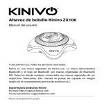
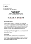
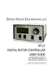
Upgrading a conventional rotator controller
PA0PLY
Introduction
Only after almost 25 years of service, my antenna rotator system died under bad circumstances.
Heavy winds and much larger load of 8 long yagi’s for 432MHz were too much for the
mechanical construction.
A new rotator was selected but it did not fulfil the todays requirements. State of art upgrading was
badly needed.
Photo 1.: Large EME array for 432MHz.
Selection
The major goal to be achieved is an mechanical strong motor gear with little backlash and
sufficient torque capabilities to withstand the windload.
From the available table, my antennas would generate a windload of about 0.6m². Unfortunately
this figure is not the only determining figure to select a rotator system.
Large arrays of antennas will cause a lot of stress to the mechanical parts. For this reason I
selected the YEASU G-1000C, to handle the next 25 years of service.
Band
(MHz)
14
14
21
21
28
14/21
14/21/28
50
50
144
144
432
432
Elements
Area
(m²)
3-elements
5-elements
3-elements
2-el Quad
3-elements
4-elem trapped
4-elem trapped
4-elements
6-elements
10-elements
10-elem x 4 x 2
12-elements
12-elem x 4 x 2
0.7
1.7
0.45
0.3
0.3
0.5
0.5
0.25
0.37
0.2
2.0
0.06
0.6
Table 1: Typical wind loading areas for common antennas
Specifications
The outside unit is a waterproof die-cast aluminium enclosure. It takes advantage of a quiet,
reliable gear reduction braking system. The inside unit is equipped with an indicator needle
system to indicate the direction of the antenna’s
Wind load:
Rotation torque:
Backlash:
Rotation time:
2.2m²
800 kg/cm
1 degree
55 sec.
Upgrade requirements.
Actually I was little disappointed after initial set-up of the rotator system in the shack. On the
indicator unit, the minimum readable indication was written to be 5 degrees only. Even worse
turns the fact that the indicator needle kept on moving while the outside unit already stopped. In
my application this is unacceptable. Besides this such a type of indicating originates from the
‘70s, rather then state of art technique. Next to the indicating problem, the speed of 55 sec for one
360 degree turn should be reduced for better handling larger loads, such as my antenna’s.
Preferable would be an adjustable rotation speed. An optional computer interface would be ideal.
Photo: 2 Front view of original control unit.
Investigation prior to upgrading
Required modifications could have been done more efficient or even better once electrical
schematics were available. Although pushed such a request forward through both the local
representative and the official importer, it became not available due to the fact it was a recently
introduced new rotor system was said.
Lacking this support, “professional” amateur sense was used to find out what’s in.
To provide speed reduction, the type of motor should be known. Most commonly a 2 phase 26Vac
motor is used, while larger systems use a 28Vdc motor. Here a DC motor is used.
Position indication originates from two wire information from the outside unit. Lucky enough all
three wires from the outside potentiometer are wired to the controller unit. In the controller unit
only two wires are used. The mechanical needle indicator system is a separate section with a small
connector plug to the indicator PCB. It can be removed as a whole, creating sufficient space for a
new, digital, type of indicator.
Photo 3: Mechanical indicator needle system
Speed reduction.
A small power PCB provides the 28Vdc for the motor unit. This PCB also contains two small
relays, which are commanded from the front buttons. A very useful type of speed control is a
pulse-controlled system. The advantage of a pulse-controlled driven motor is that it will not loose
its torque. In HAM radio, WB4EXW published a simple circuit, which can be used either for DC
or AC motor systems. It provides adjustments for both pulse rate and width to tailor it to your
application. A two colour LED was added to indicate the direction and rate of the motor. The LED
was mounted in the centre hole of the indicator scale and connected in parallel to the motor wires.
The speed reduction circuit is mounted in between the minus track o the PCB board. This copper
track must be cut just before the connection to the two relays. For AC motors the FET device must
be replaced by a TRIAC.
Figure 1 Diagram for speed reduction
Digital indicator.
Using a 3-digit digital voltmeter PCB, it provides a 1 degree accuracy indication, directly reading
the voltage from the outside unit. Therefore there is a need to have access to all three wires of the
potentiometer. Since no spare parts for the cable connector could be provided, a new connector
system replaces the original connections. It now allows all 6 wires to enter the control unit,
leaving 1 wire’s purpose unknown.
Using a 3-digit voltmeter, such as the Velleman kit: K2032 used here, requires a 0-360mV to
show 0-360 degrees. The kit provide both offset null and gain adjustments, which can be
effectively used to calibrate the new indicator. In turn voltage divider systems can be used to set
for a maximum voltage of 360 mV for this meter. The supply voltage to the outside unit
potentiometer is chosen to be 5 Volt, from a 7805 voltage stabiliser. Since the outside resistor
covers an over range up to 400 degrees, this voltage is sufficient. A slightly higher voltage will be
required for one who needs exactly 3.6 Volt for 360 degrees. (Using 5 Volt it provides about 3.4
Volt at 360 degrees).
Photo 4: Front view modified control unit.
Mechanical construction
The speed reduction PCB is mounted on the rear wall of the control unit. The speed adjustment
can be reached from the rear side of the unit. Pulse rate is shown from the flashing LED on the
front, while the colour indicates the direction of movement. Red colour for right and green for left.
The entire mechanical indicator is removed. Also the indicator scale and its plastic cover is
temporary removed for rework. A small rectangular hole is prepared just above the horizontal
centre line. This area accepts the three 7-segment displays of the voltmeter. On the plastic scale
we have to remove a part of the vertical white line crossing the voltmeter indicators. Carefully,
again carefully apply some solvent, such a nail polish remover to remove this white line pointing
to the 0 degree direction. Using to much solvent will affect the plastic cover as well!! A small
PCB is constructed, housing the 5 Volt regulator for the digital voltmeter as well as for the
potentiometer voltage supply. Voltage reduction dividers using a 10-turn potentiometer is also
available on this board. Using stand-offs it can be mounted on the bottom of the control unit.
Photo 5: Position of speed reduction PCB
Adjustment and calibration.
Speed adjustment is straight forward and much dependent o the type of antenna’s used as well as
the final application. In my application using the array for EME contact, I set the system for a 360
degree turn in 8 minutes.
Calibration of the digital indicator must start at the 0 degree mechanical position. Here one should
compensate any indication using the offset control of the digital meter system. Next prepare a
small mark on the outside of the motor base and turn it for 360 degrees. Using the gain and/or 10turn “poti” carefully adjust the indicator for a 360 degree display.
The outside potentiometer is linear thus after this adjustment you will find the 270, 180 and 90
degree positions to match with the mechanical position as well.
Computer control
Adding a 9-pin Sub-D connector, a simple interface can be created. Two pins are connected from
the direction buttons, with reference to a third pin supplying 12Vdc.
Two other pins are used for an analogue voltage output of 0-3.6Volt. Using an A/D converter it
will provide digital information required for most tracking systems such as the F1EHN
moontracking interface.
Photo 6: Rear view of modified control unit.
Conclusion
Spending a budget of about Euro 70,=, a commercial antenna rotator system of Euro 900,=
become a valuable instrument in today’s radio amateur shack. At least manufacturers should be
able to include this type of upgrades for much less in their current controllers.
References:
HAM-RADIO 1981- January
YAESU MUSEN Co., Ltd
Velleman Components
Pulse-position control of the CDE Tailtwister rotor
W.R. Gabriel, WB4EXW
User manual G-1000C
Catalog, http://www.velleman.be