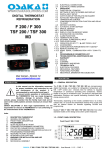
1
USER MANUAL FOR DIGITAL
THERMOSTAT
COOL / HEAT WITH DEFROST
F 100 / TSF 100 / M1
4.3
4.4
4.5
4.5.1
4.5.2
4.6
4.6.1
4.7
4.7.1
4.7.2
5
6
6.1
6.2
6.3
7
7.1
7.2
7.3
7.4
THERMOSTAT TEMPERATURE
COMPRESSOR PROTECTION
DEFROST CONTROL
MANUAL DEFROST
LOCK DISPLAY DURING DEFROST
ALARM FUNCTIONS
TEMPERATURE ALARMS
ACCESSORIES
OSAKA SETUP + USB KEY: PROGRAMMING KEY
X2 - REMOTE DISPLAY
LIST OF PARAMETERS
TROUBLESHOOTING, MAINTENANCE AND
WARRANTY
SIGNALS
CLEANING
WARRANTY AND REPAIR
TECHNICAL DATA
ELECTRICAL FEATURES
MECHANICAL FEATURES
FUNCTIONAL FEATURES
MECHANICAL DIMENSIONS AND MOUNTING
1 – DESCRIPTION OF DEVICE
1.1 – GENERAL DESCRIPTION
The F 100 / TSF 100 / M1 are digital electronic thermostats with
suitable microprocessor for refrigeration and industrial processes,
equipped with temperature control with ON / OFF control and
defrost compressor stoppage time intervals.
Thermostats have a relay output and an input for temperature
sensor PTC or NTC and also an internal buzzer for acoustic
signalling ALARM and programming.
User’s Manual – V2
www.osakasolutions.com
INTRODUCCIÓN
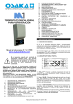
1.2 – DESCRIPTION OF FRONT PANEL
F 100 Front panel
In this manual are the information necessary
for proper installation and instruction for use
and maintenance of the product, it is
recommended to read carefully and keep it.
To prevent erratic operation or malfunction of
the THERMOSTAT that can create dangerous
situations, damage to persons, things or
animals, please remember that the facility must meet and be
aware of the safety systems annexes necessary to ensure their
safety.
OSAKA SOLUTIONS or their legal representatives are not
responsible for misuse of THERMOSTAT or not conforming to
the characteristics of the THERMOSTAT.
Index
1
1.1
1.2
2
2.1
2.2
2.3
2.4
2.5
2.6
3
3.1
3.2
3.3
3.4
4
4.1
4.2
Models F 100 / TSF 100 / M1 differs from other standard models for
the design and screen system keyboard.
DESCRIPTION OF DEVICE
GENERAL DESCRIPTION
DESCRIPTION OF FRONT PANEL
PROGRAMMING
MODIFICATION OF SET POINT
PROGRAMMING PARAMETERS
PASSWORD PROTECTION PARAMETERS
CUSTOMIZING SETTINGS
RESTORATION INITIAL PARAMETERS
KEY LOCK FUNCTION
INSTRUCTIONS FOR USE AND INSTALLATION
USE
MECHANICAL ASSEMBLY
ELECTRICAL CONNECTIONS
ELECTRICAL WIRING DIAGRAM
OPERATION
FUNCTION ON / OFF (STAND-BY)
MEASURE AND DISPLAY
TSF 100 Front panel
M1 Front panel
OSAKA - F 100 / TSF 100 / M1 - Manual de Usuario – V2 - PAG. 1
1 - Key “SET”: Pressing and releasing, programming control value In some cases, this password is very useful so that no improper
handling in, if you want to change the password once entered the
(Set point). Keeping for 5 seconds, the setup menu entry.
desired number and password in the "t, PP" parameter, Exit
2 - DOWN Key: Pressing directly without entering the menu, serves programming.
to decrease the value of the SET POINT. On the menu parameters When the password is programmed, pressing "Set" for 5 seconds
used to search the desired parameter and after pressing the to enter the settings menu, the computer displays the acronym 'rP"
selection parameter "SET" serves to diminish or select the new and pressing "Set" show "O", then we select the buttons "up" or
value of the parameter.
"down" the value of correct password code and press "set" to
proceed to access the programming parameters.
3 - UP / DEFROST Key: Holding down for 5 seconds to start a If the password is correct, the display will show the code of the first
manual defrost (if the conditions of end defrost probe has no value parameter. The password protection can be disabled with the
beyond the end of defrost).
"t.PP" = oF parameter.
In the parameter menu is used to find the desired parameter and
after pressing the selection parameter "SET" serves to increase or Note: If lost the password to access the parameters, use the
select the new value of the parameter.
following procedure:
Turn off electrical power to the computer and re-feeding while you
4 - Key
/ "F": It is possible to perform 3 functions:
press the "SET" button for 5 seconds. Access parameters will be
a) Shows the value of the evaporator probe, or the third probe (in taken and you could modify the "t.PP" parameter.
the case of being programmed).
b) Pressing for 1 second can power cycle the device (ON / OFF), 2.4 CUSTOMIZING SETTINGS
programming the "UF" parameter.
The password protects with just a few other parameters without
c) Exit Parameter Programming
password in order to let the user access to the parameters
required, while access to all parameters that are specific technical
5 - Led SET: Indication shown in the programming mode the set or machine manufacturer.
point. In the parameter menu, indicates the level of programming Method to select the level of programming parameters:
said parameter.
Access programming through password and select the parameter
to be programmed without password. If the SET LED flashes
6 - Led OUT COOL: Indicates the status of the control output means that the parameter is programmable only with the password,
(compressor or control device temperature, solenoid actuator, etc..) or protected, and if the LED is fixed indicates that the parameter is
This output is active (lit) and off (off) and disabled signal (flashing). direct access without password.
To change the level of visibility of the parameter press together "Up
7 - Led OUT HEAT: Identical to "Led OUT COOL", but for the heat + Set" keys.
function.
The SET LED will change state in indicating the new access level
parameter (protected, flashing LED) and (direct access without
8 - Led DEF: Indicates the current status of defrost, Pilot flashing password, fixed LED).
Upon entering the first parameter menu visualize user level
indicates defrosting is being done.
parameters (unprotected) and then (protected) by entering the
9 - Led ALARM: Indicates the status of the alarm. ON (lit) OFF password if the device shows "rP"
(stopped) or Ongoing (intermittent)
10 - Led Stand-By: Indicates he's Stand-By
(Press Key
or "F" for 3 seconds to activate or digital input).
2 - PROGRAMMING
2.1 - MODIFICATION OF SET POINT
Press the "SET" key and release, the display will show "SP"
alternating control value.
To change the value, press "up" to increase value and "down" to
descend.
If "Up or Down" key is held quickly increase speed to help select a
distant value.
After selecting the desired value is confirmed by pressing "SET" or
self confirm whether any last key pressed 10 seconds, turning the
thermostat to normal operation.
2.2 - PROGRAMMING PARAMETERS
If the Password parameter access is not enabled (default setting),
press "SET" for 5 sec., The display will show the code that
identifies the first parameter and the "Up" or "Down" button you 2.5 – RESTORATION INITIAL PARAMETERS
can select the desired parameter.
The device has a parameter reset, restoring the program to Factory
Settings.
After selecting the desired parameter, press the "SET" key and the To enter this Reset "rP" the password value to “- 48“
value will be programmed to the desired parameter. This setting The display will show "---" and the instrument will reset.
can be changed by pressing the "Up" or "Down" to the desired
value. Press "SET" to confirm and store the value.
2.6 - KEY LOCK FUNCTION
Returning to the "Up" or "Down" keys again be possible to select It is possible to completely lock the keys. Such a function is useful
another parameter and modify it on.
when the control is accessible to the public and you want to prevent
To exit the programming mode: do not touch any key for 10 tampering. The key lock function is activated by setting the "t.Lo"
seconds or press the or "F" key for 2 sec.
parameter to a value of OF.
The value set in par. "T.Lo" is the time that the thermostat allows
2.3 - PASSWORD PROTECTION PARAMETERS
access to the keyboard and after passing this time the thermostat
The instrument has a parameter protection function with is locked.
configurable password code in the "t, PP" parameter.
OSAKA - F 100 / TSF 100 / M1 - Manual de Usuario – V2 - PAG. 2
Pressing any key displays the thermostat "Ln" to inform the lock is 3.4 – ELECTRICAL WIRING DIAGRAM
activated.
To unlock the keyboard press "Set + Up" for 5 sec., The display will Wiring scheme of F 100 and TSF 100
show "LF" and all keyboard functions again become operational.
1 6 A -A C 1 (6 A -A C 3 ) / 2 5 0 V A C ;
1 H P 2 5 0 V A C , 1 /2 H P 1 2 5 V A C
3 – INSTRUCTIONS FOR USE AND INSTALLATION
S P S T -N O
IN T E R N A L
NO
C
BUZZER
3.1 – USE
SPDT
Z31
The devices are made as measuring and regulating equipment in
NO
NC
C
IN P U T
accordance with EN 61010-1 norm for operation up to an altitude of
1 2 3 4 5 6 7 8 9 10 11 12
2000 mts.
OUT
The use of equipment for standard applications not expressly
SU PPLY
provided in norm cited above, should provide all measurement and
adjustments necessary protection.
The equipment must be adequately protected and away from
PROBE
liquids, dust, grease and dirt. They must be accessible only with the
use of a right tool and safety system (except the front).
The devices can NOT be used in dangerous environments Wiring scheme of M1
(flammable or explosive) without adequate protection.
It is recalled that the installer must ensure that the norm for
100...240
Probe
electromagnetic compatibility is respected after implantation in the
VAC
INTERNAL
installation of equipment, eventually using the right filters if is
BUZZER
SUPPLY
needed.
OUTPUT
In case of failure or malfunction of measuring and control
1 2 3 4
6 7 8 9 10 11 12
equipment that can create dangerous situations or damage to
NC
NO C
persons, things, animals or products (defrost food or changes in
INPUT
their ideal state), it is recalled that the facility should be equipped
with electronic devices or electromechanical safety and warning
system.
8A-AC1 (3A -AC3) / 250 VAC;
They should be placed outside the measuring and control
1/2HP 250VAC,1/3HP 125VAC
equipments, possible protective devices, responding to specific
safety requirements that are covered by the norm of the product or 4 - OPERATION
suggest the common sense.
For your own safety, is highly recommended fulfilling the 4.1 – FUNCTION ON / OFF (STAND-BY)
instructions provided above.
The once fed can make 2 states:
- ON: means that the driver is running and acting on the basis of
planned control.
3.2 - MECHANICAL ASSEMBLY
The thermostat housing 32 x 74 mm is designed for wall mounting - STAND-BY: means that the control does not acts, stop. (The
or wall using the holes in the plastic and predisposed accessible display illuminates the LED Stand-by).
after removing the front.
The situation of a stand-by is a failure of regulation is often useful
Once the equipment is installed is recommended to close the front to use the front keypad as selector stop / start mode.
cover.
The key or "F" pressed for 3 sec Lets stop to change gear or vice
Avoid placing the thermostat in place exposed to high humidity or versa always par. "T.UF" = 4.
dust, this can cause condensation or introduction of conductive
particles or substances. Ensure that you have adequate ventilation 4.2 – MEASURE AND DISPLAY
and avoid installing indoor sealed boxes or areas where the By the par. "I.SE" is selected if the probe you want to use is the
temperature exceeds the specifications of the team. Avoid installing type KTY81 PTC-121 (Pt) or NTC 103AT-2 (nt).
the cables and power supply together with the probe out and install With the par. "UP" is selected if the unit of measure to use is the
equipment that can generate disturbances (electrical noise) as temperature in degrees Celsius (Standard) or Fahrenheit (USA)
motors, fans, inverters, automatic gates, contactors, relays,
(C0 = ° C / 1 ° (no decimal); C1 = ° C / 0.1 ° (with decimal ) F0 = ° F
solenoids, etc...
/ 1 °, F1 = ° F / 0.1 °).
3.3 – ELECTRICAL CONNECTIONS
The thermostat is designed for permanent connection between
devices, no switch is equipped with internal devices of potency for
overcurrents or overvoltages. It is therefore recommended to install
a equipment as close and easy access to court if necessary, as a
general safety thermal / isolator switch / device magneto. Are
reminded that you must use appropriate wire to own isolation
voltage, current, temperature and local electrical codes should also
separate the signal wires from the power probe and power as far as
possible in order avoid possible electrical noise, electromagnetic
induction, which in some cases could be diminished or cancelled
with RC filters, ferritic, supply, resistors, etc. ... the use of wires with
antiparasitic mesh and this mesh is recommended to connect on
one side to take ground.
It is recommended to check that the equipment settings are
appropriate to the application before connecting wires actuators,
loads on the output relays in order to prevent malfunctions or
damage.
The calibration of the measurement can be done in 2 ways, the
overall correction instrument is calibrated using the parameter.
"I.C1". visualization and regulation. (Standard)
Or the parameter. "I.CU" which allows an offset to be applied only
to the display screen (the control will be controlled depending on
only the correction of the "i.C1" parameter).
By the par. "I.Ft" may introduce a software filter for measuring the
input value mode to decrease sensitivity to rapid changes in
temperature (increasing time). The instrument displays the
temperature measurement is even possible to see the maximum
and minimum peak measured by key or "F".
Quickly by pressing
or "F" display will show alternately:
"Lt" is the low temperature stored
"Ht" is the maximum temperature stored
"Pr1" is the instantaneous temperature.
The minimum and maximum peak is reset by removing power to
the device or press the "Down" key 3 seconds during viewing the
value of max. or low. Once reset visualize "---"
Of display Menu at max. and min. the device will automatically exit
in 15 seconds.
OSAKA - F 100 / TSF 100 / M1 - Manual de Usuario – V2 - PAG. 3
Remember that the display on the probe can be modified by the The third time provides permit no starts if has exceeded the
display lock function with parameter defrosting. "D.dL" (see programmed time between consecutive starts. Parameter "P.P3"
(delay after consecutive starts).
function. "Defrost").
4.3 – THERMOSTAT TEMPERATURE
The mode of regulation of the instrument is the ON / OFF type on
the relay outputs depending on the probe and the active Set Point
"SP" and the differential (hysteresis) intervention "rd" and mode
"r.HC".
In the operation mode set in the "r.HC" parameter applies to the
following differential: ("r.HC" = C) setting cold (cold) the differential
used as positive and triggers the relay to reach the set point and
stops again until the temperature exceeds the set point +
differential. If ("r.HC" = H) configuration Heat (Heat) the differential
used as negative and triggers the relay to reach the set point and
stops until the temperature drops again below the set point differential.
Tem p.
Tem p.
SP
r.d
r.d
Tem p.
r .d
SP
ON
O ut
ON
ON
o ff
P .P 3
o ff
P .P 3
tim e
o ff
P .P 3
If protection is acting, hindering the progress of the relay for the
programmed time, the relay output LED (Cool or Heat) is flashing.
Is possible activate a delay to the start of the regulation to when
arrives the supply to the thermostat. Parameter "P.od" very suitable
when multiple thermostats to not start at the same time allowing the
loads and power line a softer boot.
During this phase delay visualize od alternating scheduled to
normal viewing.
The delay function "od" = disables programming as oF.
SP
tim e
ON
O ut
ON
o ff
tim e
ON
ON
O ut
o ff
r.H C = C
ON
o ff
ON
o ff
r.H C = H
4.5 – DEFROST CONTROL
The defrost timer is type "compressor failure" at scheduled
intervals.
Defrost is programmed in the parameter "D.Di" time between
defrost cycles between the end of one and beginning of the
successive. We can force a defrost at first start defrost, par.
"D.Sd".
If you want each instrument start defrosting is done schedule time
parameter "d.Sd" = oF. So starting immediately conduct one.
If you do not want to start defrosting then will the defrost cycle for
this program "d.Sd" = "D.Di".
Programming "D.Di" = oF all defrosting is disabled. Therefore, the
instrument provides each defrost, compressor disable relay for the
time "d.dE".
In case of probe error is possible that the output programmed as
function ot cycling time programmed on par. "R.t1" (activation time)
and "r.t2" (deactivation time) for error.
Programming "t1" = oF the output probe condition remains always
off.
Programming "r.t1" any value "r.t2" = oF the output in probe error
condition will remains On.
It is recalled that the operation temperature can be conditioned on
the following functions:
4.5.1 – MANUAL DEFROST
"Compressor Protection", "Delay-start" and "Defrost".
To activate a manual defrost press the "Up / DEFROST" button for
5 seconds and the led "Def" lights and perform defrosting. To
4.4 – COMPRESSOR PROTECTION
terminate a defrost cycle while doing this press the "Up / Def"
Compressor protection feature helps to avoid very frequent button again for 5 seconds.
compressor starts or it can also be useful for control in time for the
relay output to an actuator or intended load. Activate this function 4.5.2 – LOCK DISPLAY DURING DEFROST
provides 3 types of timing choice as appropriate to the control
Using parameters "d.dL" and "A.Da" display behaviour is
system.
established during defrosting.
The protection is to prevent multiple starts during the time of
The "d.dL" parameter causes blockage of the last temperature
protection.
before defrost on the display ("d.dL" = on) until you reach the end
The first provides a delay time to the activation of the output of defrost and the temperature does not exceed below the value of
the last preset temperature or condition ["SP" + "rd"], or times out
according to the time set in the "P.P1" parameter (delay to start).
lock security. "A.Da".
Also allows visualization of the indicative initials Defrost "dEF" ("dl"
Tem p.
= Lb) and after defrost the acronym "PdF" indicating time defrost
r .d
finish temperature cold but not recovered to control value ("SP" +
SP
"rd") or times out lock security. "A.Da".
ON
ON
ON
Another possibility is to indicate the actual temperature of the cold
tim e
chamber or cabinet, during defrosting ("d.dL" = oF).
O u t o ff
o ff
o ff
o ff
4.6 - ALARM FUNCTIONS
Alarm conditions:
The second time provides a delay of control relay, in order to - Probe Error: "E1", "-E1"
ensure a minimum time between the arrest and the progress of the - Temperature alarm: "Hi", "Lo"
relay parameter: "P.P2" (delay after stop or minimum downtime).
The alarm function is displayed in LED and ALARM programmable
internal buzzer in the "o.bu" parameter.
Tem p.
The pair. "O.bu" allows the configuration of the internal buzzer:
= OF - off buzzer
r .d
SP
= 1 - the buzzer is activated only for alarm signals
= 2 - the buzzer is activated only to point out the key presses and
ON
ON
ON
tim e
no warning signs.
O ut
= 3 - The buzzer is activated only to point out the keystrokes and
o ff
o ff
o ff
alarm signals.
P .P 2
P .P 2
P .P 2
OSAKA - F 100 / TSF 100 / M1 - Manual de Usuario – V2 - PAG. 4
Any alarm condition is indicated by the LED ALARM while the
condition is pre alarm or alarm delay is indicated by the flashing
LED. The buzzer can be configured to signal alarms the par. "O.bu"
= 1 or 3 and can be deactivated in case you are playing with the
press of a key.
4.6.1 – TEMPERATURE ALARMS
The alarm function is a function of temperature reading from the
probe, and the type of programmed alarm parameter. "A.Ay" and
the alarm set point par. "A.HA" (maximum alarm) and "A.LA"
(minimum alarm) and the relative differential "A.Ad".
Through the "A.Ay" parameter you can specify whether the alarm
set "A.HA" and ".LA" should be considered absolute ("A.Ay" = 1) or
relative to the Set Point ("A.Ay" = 2).
By some parameters may delay activation, if the situation is
cancelled recovering optimal conditions, without becoming alarm.
These parameters are:
"A.PA" - delay in receiving the alarm and turn on the power control
equipment, should be in alarm.
"A.Da" - delay after defrost (A. maximum) or after a continuous
cycle (A. Min).
"A.At" - delay of the performance of temperature alarm.
The differential alarm will be the same set in parameters "A.HA"
and "A.LA" if alarms are absolute ("A.Ay" = 1).
SU PPLY
USB
SU PPLY AD APTER
SUPPLY AD APTER
12 VDC
12 VDC
AC SU PPLY
AC SU PPLY
USB
Tem p.
A .H A
A .A d
SU PPLY AD APTER
A .A d
A .L A
ON
AL
SU PPLY AD APTER
12 VDC
o ff
Hi
ON
o ff
Lo
t im e
12 VD C
AC SU PPLY
AC SU PPLY
o ff
Or shall result from: ["SP" + "A.HA"] and ["SP" + "A.LA"] if the
alarm is on ("A.Ay" = 2).
4.7.2 – X2 - REMOTE DISPLAY
The equipment you can connect a remote display device X2 by a
cable that can be up to 10 meters at maximum. The X2 device
powered directly from the device, displays temperature measured
by the probe Pr1 by a 2-digit display and a half.
Tem p.
A .A d
A .H A
SP
A .L A
A .A d
ON
AL
o ff
Hi
ON
o ff
Lo
t im e
o ff
The maximum and minimum alarm temperature can be disabled
setting: "A.HA" e "A.LA" = oF.
4.7 – ACCESSORIES
4.7.1– KEY USB + OSAKA SETUP: KEY PROGRAMMING
Extracting the box you have access to a white connector that allows
easy programming with programming key 5 pin. This key allows
repetitive schedules and save the settings in a practical and simple.
There are 2 types of Key, the key enabling USB connection pc and
save the different configurations and set parameters and Manual
Key 5 pin only for connecting thermostats.
An advantage and recommendation is the use of the supplied
power supply KEY without connecting the F 100 / TSF 100 / M1 to
power.
OSAKA - F 100 / TSF 100 / M1 - Manual de Usuario – V2 - PAG. 5
5 – LIST OF PARAMETERS
Parameter listing. Some of them might be on the menu with
password and some without, shortcut or may not be present
depending on the model:
Par.
1
2
3
4
5
6
7
8
9
10
11
12
13
Description
Range
Def.
S. – Parameters Set Point value to regulate
-99.9 ÷ HS
-50.0
S.LS Minimum Set Point
LS ÷ 999
99.0
S.HS Maximum Set Point
-LS ÷ HS
0.0
SP Set Point
i. - Probe parameters selection and correction
Pt / nt
nt
i.SE Type of probe
C1
i.uP Unit of measure and C0 / F0 / C1 /
resolution
(decimal
F1
point)
C0 = ° C without p.dec
1º
F0 = ° F without p.dec
1º
C1 = ° C with 0.1 ° dec
F1 = ° F with 0.1 ° dec
oF ÷ 20.0
2.0
i.Ft Measuring filter
sec
-30.0 ÷ 30.0
0.0
i.C1 probe calibration
°C/°F
r. – Parameters of temperature regulation
0.0 ÷ 30.0
2.0
r.d Differential
(Hysteresis) regulation
°C/°F
r.t1 Output relay activation oF/ 0.01 ÷ 9.59 oF
time for probe faulty or
(min.sec ) ÷
broken
99.5
(min.sec.x10)
r.t2 Stop time relay output oF/ 0.01 ÷ 9.59 oF
for faulty sensor or
(min.sec ) ÷
broken
99.5
(min.sec.x10)
mode
H-C
C
r.HC Operating
output:
H = Heat (heat)
C = Cold (cold)
d. – Defrost Control Parameters
oF/ 0.01 ÷ 9.59 6.00
d.di Interval between
defrost
(h.min. ) ÷ 99.5
(hrs.min.x10)
to
start oF/ 0.01 ÷ 9.59 02,0
d.Sd Delay
defrosting
(h.min. ) ÷ 99.5
(oF = defrost at start)
(hrs.min.x10)
14 d.dE Duration defrost
oF/ 0.01 ÷ 9.59
(min.sec ) ÷
99.5
(min.sec.x10)
display during oF - on - Lb
15 d.dL Block
defrost:
oF = not active
on = Active with last
measure
Lb = active with
abbreviations ("dEF"
defrosting and "PdF" in
Post-defrost
recovering)
Note
18 P.P3 Minimum time after two oF/ 0.01 ÷ 9.59 oF
starts departure.
(min.sec ) ÷
99.5
(min.sec.x10)
19 P.od Output activation delay oF/ 0.01 ÷ 9.59 oF
at start (supply)
(min.sec ) ÷
99.5
(min.sec.x10)
A. – Alarm parameters
20 A.Ay Temperature
alarm
1/2
1
type:
(/ 3 / 4 / 5 / 6 /
1 = Absolute
7 / 8 = No use)
2 = Relative
21 A.HA Set alarm for high
oF / -99.9 ÷
oF
temperature
999 °C/°F
22 A.LA Set alarm for low
oF / -99.9 ÷
oF
temperature
999 °C/°F
23 A.Ad Differential
0.0 ÷ 30.0
1.0
temperature alarm
°C/°F
24 A.At Temperature alarm
oF/ 0.01 ÷ 9.59 oF
delay
(min.sec ) ÷
99.5
(min.sec.x10)
25 A.PA Delay of temperature
oF/ 0.01 ÷ 9.59 2.00
alarm at start (power) (h.min. ) ÷ 99.5
(hrs.min.x10)
26 A.dA Delay of temperature
oF/ 0.01 ÷ 9.59 1.00
alarm after defrost
(h.min. ) ÷ 99.5
defrost lock display
(h.min.x10)
o. – Buzzer alarm configuration parameters
27 o.bu buzzer operation
oF / 1 / 2 / 3
3
oF = disable
1 = one alarm
2 = only for keyboard
use
3 = active alarm and
keypad
t. – Keyboard Configuration Parameters
28 t.UF Operation mode key
oF / 4
4
"F" or .
(1 / 2 / 3 = No
oF = no function
use)
4 = On / stop (Standby)
29 t.Lo Automatic keyguard
oF/ 0.01 ÷ 9.59 oF
(min.sec ) ÷
30.0
(min.sec.x10)
30 t.PP Password access to
oF ÷ 999
oF
operating parameters
oF
6 – TROUBLESHOOTING, MAINTENANCE AND WARRANTY
oF
P. Parameters relating to the protection of the compressor
and delay starting.
16 P.P1 Exit delay activation
oF/ 0.01 ÷ 9.59 oF
(min.sec ) ÷
99.5
(min.sec.x10)
17 P.P2 Disabling postarrest
oF/ 0.01 ÷ 9.59 oF
output (relay)
(min.sec ) ÷
99.5
(min.sec.x10)
6.1 – SIGNALS
Error
Reason
Action
The relative probe can
be broken (E) or in short
circuit (-E), or may have
a value that is out of
range programmed
Check the connection of
the probe to the
instrument and verify the
correct operation of the
probe. (it helps to have
the ohms values of the
probes)
EPr
Possible anomaly in
EEPROM
Press the SET key.
Power cycle the
instrument
Err
Fatal Error device
memory
Replace the device or
send it to any repair
E1 -E1
OSAKA - F 100 / TSF 100 / M1 - Manual de Usuario – V2 - PAG. 6
In probe error condition the output behaves as scheduled Measuring range: NTC: -50 ... 109 ° C / -58 ... 228 ° F; PTC: -50 ...
150 ° C / -58 ... 302 ° F
parameters "t1" and "t2".
Display resolution: 1 ° or 0.1 ° (pitch -99.9 .. 99.9 ° C)
Total accuracy: + / - (0.5% FS + 1 digit)
Indication on
Reason
Time measured speed (no filter): 130 ms
Display
Display: 3 Digit 15.5 mm h
Delay-start after power equipment
od
Software class structure: Class A
keypad Locked
Ln
Compliance: Directive 2004/108/EC (EN55022 class B, EN61000Defrost active display if "d.dL" = Lb
dEF
4-2: 8KV air, 4KV cont; EN61000-4-3. 10V / m, EN61000-4-4: 2KV
Defrost finish recovering cold if "d.dL" = Lb
PdF
power, inputs, outputs; EN61000-4-5: com 2KV power mode, 1 kV \
High temperature alarm
Hi
diff mode, EN61000-4-6:.. 3V), 2006/95/EC (EN 60730-1, EN
Low temperature alarm
Lo
60730-2-7, EN 60730-2 -9)
7.4 – MECHANICAL DIMENSIONS AND MOUNTING
6.2 - CLEANING
We recommend cleaning with a damp cloth only without detergent
F 100
or detergent.
6.3 – WARRANTY AND REPAIR
This device has a guarantee in form of repair or replacement by
manufacturing defects in materials of 12 months from the date of
purchase.
OSAKA SOLUTIONS automatically void this guarantee and is not
liable for any damages deriving from:
- Use, installation, or use and handling undue, others than
those described above and, in particular, differs from the
safety requirements established by the regulations.
- Use in applications, machines or electrical panels that do
not provide adequate protection against liquids, dust,
grease and electric shocks to the installation conditions
made.
- The inexperienced handling, and / or alteration of the
product.
- The installation / use in applications, machines or
electrical panels do not comply with the valid norm.
In case of defective product under warranty or out of that period, it
should contact the post sales service to perform the necessary
steps. Request document repair "RMA" (by mail or fax) and
complete it, is necessary send the RMA and the device to SAT
OSAKA by method prepaid.
TSF 100
7 – TECHNICAL DATA
7.1 – ELECTRICAL FEATURES
Supply: 12…24 VAC/DC (F 100) - 100...240 VAC +/- 10%
Frequency AC: 50/60 Hz
Consumption: 4 VA
Input /i: 1 input for temperature sensor NTC (103AT-2, 10 K Ω @
25 °C) o PTC (KTY 81-121, 990 Ω @ 25° C)
Output: 1 Relay SPDT
M1: 8A-AC1 (3A-AC3) / 250 VAC
F 100 / TSF 100: 16A-AC1 (9A-AC3) / 250 VAC
Electrical life relay output: 100000 op.
Power supply: EN 60730-1 type 1.B
Overvoltage category: II
Device Class: Class II
Isolation: Isolated by piece low voltage (power 115/230 V and relay
outputs); and part low voltage inputs; Electrically isolated between
output and supply.
M1
7.2 - MECHANICAL FEATURES
Carcase: Plastic self-extinguishing UL 94 V0
Category of resistance to heat and fire: D
Dimensions: 78 X 35 mm, prof. 64 mm
Weight: 120 g approx.
Installation: on panel, recessed 71x29mm
Connection: Terminal block 2,5 mm2
Sealing degree: IP65
Ambient operating temperature: 0 T 50 ° C
Operating humidity: <95% RH non-condensing
Storage and transport temperature: -25 ° C T 60
HOLES PANEL
- F 100/100 TSF: 29 x 71 mm
7.3 - FUNCTIONAL FEATURES
Temperature regulation: ON / OFF
Defrost control: interval for compressor failure.
FIXING
- F 100/100 TSF: lateral Staples
- M1: Area through screw
OSAKA - F 100 / TSF 100 / M1 - Manual de Usuario – V2 - PAG. 7