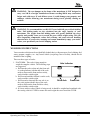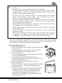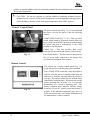
1
Where Tradition
and Innovation
Meet...
Model Year 2003
Type C Motorhome
Owner’s Manual
E
S
C
A
P
A
D
E
y
WARNING: Read all instructions in manual before using your camper.
This manual has been provided by Jayco, Inc. for the sole purpose of providing
instructions concerning the operation and maintenance of this vehicle and its
components. Nothing in this manual creates any warranty, either expressed or
implied. The only warranty offered by Jayco, Inc. is as set forth in the limited warranty
applicable to this vehicle.
The owner’s failure to provide required service and/or maintenance could result in the
loss of warranty. The owner should review Jayco’s limited warranty and the limited
warranties of all other manufacturers offering them that are applicable to this vehicle.
Instructions are included in the manual for operating various components which are
optional on some vehicles. In addition, the owner should refer to individual
manufacturer’s operating instructions contained in the owner’s packet.
©2001 Jayco, Inc. LITHO U.S.A.
06/02 ** 03-2
PART NO. 00500742
YOUR NEW JAYCO IS YOUR PASSPORT TO A WHOLE WORLD OF NEW FRIENDS
CAMPING FUN AND TRAVEL ADVENTURE WHEN YOU JOIN THE THOUSANDS OF
JAYCO FAMILIES WHO MAKE UP THE . . .
INTERNATIONAL JAYCO JAFARI TRAVEL CLUB
You will find us enjoying the friendship and fellowship of JAFARI CAMPING as we join our
local area FLIGHTS at hundreds of weekend camp-outs all over North America each month . . .
WE’RE THE FAMILIES OF JAYCO!
There are special STATE, REGIONAL and INTERNATIONAL RALLIES where you can
join with your fellow JAFARIANS and their flights to enjoy a special kind of togetherness . . .
fun, games, and entertainment provide memories to last a lifetime.
And . . . how about the exotic surroundings of NEW ORLEANS, the sounds and color of
NASHVILLE and the GRAND OLE OPRY, the mystery of MEXICO., the roar and rush of the
INDIANAPOLIS 500, the quiet surroundings of the CANADIAN ROCKIES, the color of the
SMOKY MOUNTAINS in the Fall. These and many other adventures can be yours when you
join . . .
THE INTERNATIONAL JAYCO JAFARI TRAVEL CLUB
Fill in the blanks on the reverse side, cut along dotted line and mail along with a check to:
INTERNATIONAL JAYCO JAFARI
P.O. Box 192
Osceola, IN 46561-0192
ATTN: Membership Director
Yes, it’s for everyone with a JAYCO; young couples just starting out, families spending quality
time together, the young at heart expanding their life experiences. Whether you belong to another
camping club, have always traveled alone, or are just starting, don’t miss out on one of the most
priceless benefits of being an RV family . . . meet new friends and spend a bit of your camping life
with some of the finest people you will ever have the opportunity to share a campfire or treasure a
moment of golden living with . . Fifth-Wheel Travel Trailer . . . Type A or Type C Motorhome. . .
Conventional Travel Trailer . . . Sport Utility Trailer . . . Folding Camping Trailer . . . it doesn’t
matter, if you are a JAYCO FAMILY, then you are eligible to become a JAFARI MEMBER.
. . . YOU WILL NEVER BE SORRY YOU MADE THE DECISION
In addition to the special International decals for your unit, distinctive patches, the HITCH
newsletter with schedules of upcoming events and activities, your membership entitles you to the
following special benefits: MEMBERSHIP ROSTER containing the names and addresses of
current members of the club. REGISTERED KEY RING, so if your keys are lost, they can be
returned to the International Office and then returned to you. DISCOUNT CARDS for several
national theme parks including, Sea World, King’s Dominion, Silver Dollar City, Adventureland
Park and Six Flags. DISCOUNT PRICES on Trailer Life and Motorhome camping magazines.
SPECIAL PRICES on Wheeler’s Guide, Woodall’s Campground Directory and the Rand
McNally road atlas. DISCOUNT PRESCRIPTION SERVICE. CAR RENTAL DISCOUNTS.
PLUS, the joy of meeting new friends and enjoying Jaytrek Adventures around the country. Start
with the first phase of your camping life . . just complete the application and forward it to the
JAFARI INTERNATIONAL TRAVEL CLUB OFFICE.
WELCOME TO THE JAFARI FAMILY!
"
TO: Membership Director, International Jayco Jafari
Please enroll us as members in the International ... We’re ready to roll to where the “friends we just
haven’t met yet” have the coffee on the fire and are waiting for us to arrive: We are ...
Name:
Spouse:
Address:
Phone:
City:
State:
Zip:
Ages of Children at Home:
Our JAYCO is a:
Our Dealer
(type & size)
Membership Dues: (One year rate $20.00)
Two years:
$35.00
Amount enclosed. $
Three years:
$50.00
Check #:
(signature)
(date)
Table of Contents
Chapter 1
Introduction To RV Ownership . . . . . . . . . . . . . . . . . . . . . . . . . . 1
Welcome . . . . . . . . . . . . . . . . . . . . . . . . . . . . . . . . . . . . . . . . . . . . 1
Safety Considerations . . . . . . . . . . . . . . . . . . . . . . . . . . . . . . . . . . . . . 2
Reporting Safety Defects . . . . . . . . . . . . . . . . . . . . . . . . . . . . . . . . . . 2
Safety in Using LP Gas . . . . . . . . . . . . . . . . . . . . . . . . . . . . . . . . . . . 2
Electrical System Safety. . . . . . . . . . . . . . . . . . . . . . . . . . . . . . . . . . . 3
Safety When Emergency Stopping . . . . . . . . . . . . . . . . . . . . . . . . . . . . . 3
Additional Safety Considerations . . . . . . . . . . . . . . . . . . . . . . . . . . . . . . 3
Insurance . . . . . . . . . . . . . . . . . . . . . . . . . . . . . . . . . . . . . . . . . . . . 4
Extended Use . . . . . . . . . . . . . . . . . . . . . . . . . . . . . . . . . . . . . . . . . . 4
Cold Weather Use . . . . . . . . . . . . . . . . . . . . . . . . . . . . . . . . . . . . . . . 4
Condensation . . . . . . . . . . . . . . . . . . . . . . . . . . . . . . . . . . . . . . . . . . 4
Chapter 2
Obtaining Service . . . . . . . . . . . . . . . . . . . . . . . . . . . . . . . . . . 5
Warranty Registration . . . . . . . . . . . . . . . . . . . . . . . . . . . . . . . . . . . . . 5
Service Procedures . . . . . . . . . . . . . . . . . . . . . . . . . . . . . . . . . . . . . . . 7
Basic Service Procedures . . . . . . . . . . . . . . . . . . . . . . . . . . . . . . . . . . 7
Dealer . . . . . . . . . . . . . . . . . . . . . . . . . . . . . . . . . . . . . . . . . . . . 8
Factory. . . . . . . . . . . . . . . . . . . . . . . . . . . . . . . . . . . . . . . . . . . . 8
Parts . . . . . . . . . . . . . . . . . . . . . . . . . . . . . . . . . . . . . . . . . . . . . 8
Owner's Responsibility . . . . . . . . . . . . . . . . . . . . . . . . . . . . . . . . . . . 8
Chapter 3
Operating and Using Your Motorhome . . . . . . . . . . . . . . . . . . . . . . 9
Weights and Cargo Capacity . . . . . . . . . . . . . . . . . . . . . . . . . . . . . . . . . . 9
Hitch - See Chapter 7 "Options" . . . . . . . . . . . . . . . . . . . . . . . . . . . . . . . 12
Loading Cargo. . . . . . . . . . . . . . . . . . . . . . . . . . . . . . . . . . . . . . . . . 12
Weighing Instructions . . . . . . . . . . . . . . . . . . . . . . . . . . . . . . . . . . . . . 13
Tires . . . . . . . . . . . . . . . . . . . . . . . . . . . . . . . . . . . . . . . . . . . . . . 14
Wheel Lugs . . . . . . . . . . . . . . . . . . . . . . . . . . . . . . . . . . . . . . . . . . 15
Fire Extinguisher . . . . . . . . . . . . . . . . . . . . . . . . . . . . . . . . . . . . . . . 15
Inspection and Maintenance . . . . . . . . . . . . . . . . . . . . . . . . . . . . . . . . 15
TV Antenna . . . . . . . . . . . . . . . . . . . . . . . . . . . . . . . . . . . . . . . . . . 16
Raising Antenna to Operating Position . . . . . . . . . . . . . . . . . . . . . . . . . . 16
To Test System. . . . . . . . . . . . . . . . . . . . . . . . . . . . . . . . . . . . . . . 16
Lowering Antenna to Travel Position . . . . . . . . . . . . . . . . . . . . . . . . . . . 16
Maintenance . . . . . . . . . . . . . . . . . . . . . . . . . . . . . . . . . . . . . . . . 16
Seat Belts . . . . . . . . . . . . . . . . . . . . . . . . . . . . . . . . . . . . . . . . . . . 17
Driving . . . . . . . . . . . . . . . . . . . . . . . . . . . . . . . . . . . . . . . . . . . . 17
Carbon Monoxide Detector . . . . . . . . . . . . . . . . . . . . . . . . . . . . . . . . . . 17
Procedures to Take During an Alarm . . . . . . . . . . . . . . . . . . . . . . . . . . . 18
Emergency Exit Window . . . . . . . . . . . . . . . . . . . . . . . . . . . . . . . . . . . 18
Setup for camping . . . . . . . . . . . . . . . . . . . . . . . . . . . . . . . . . . . . . . . 19
Storing Your Motorhome . . . . . . . . . . . . . . . . . . . . . . . . . . . . . . . . . . . 20
Chapter 4
The Systems. . . . . . . . . . . . . . . . . . . . . . . . . . . . . . . . . . . . . 21
Plumbing System . . . . . . . . . . . . . . . . . . . . . . . . . . . . . . . . . . . . . . . 21
City Water Connection. . . . . . . . . . . . . . . . . . . . . . . . . . . . . . . . . . . 21
Tanks . . . . . . . . . . . . . . . . . . . . . . . . . . . . . . . . . . . . . . . . . . . . 22
12-Volt Demand Pump. . . . . . . . . . . . . . . . . . . . . . . . . . . . . . . . . . . 22
i
Faucets . . . . . . . . . . . . . . . . . . . . . .
Outside Shower (Option) . . . . . . . . . . . .
Sanitizing the Potable Water System . . . . . .
Bath and Shower . . . . . . . . . . . . . . . . .
To Empty the Water System . . . . . . . . . . .
Sanitation System . . . . . . . . . . . . . . . . . .
Toilets . . . . . . . . . . . . . . . . . . . . . .
Operating Instructions - Aqua Magic® 4 . . . .
Toilet Maintenance . . . . . . . . . . . . . . .
Vents . . . . . . . . . . . . . . . . . . . . . . .
Holding Tanks . . . . . . . . . . . . . . . . . .
Using Toilet and Tank System . . . . . . . .
Sewage Tank Preparation . . . . . . . . . . .
Gray Water Holding Tank . . . . . . . . . .
Draining the Holding Tanks . . . . . . . . .
Winterizing Your Motorhome . . . . . . . . . . .
Using the Water System During Freezing Weather.
The LP Fuel System . . . . . . . . . . . . . . . . .
LP Container . . . . . . . . . . . . . . . . . . .
Fuel Distribution Components . . . . . . . . . .
Checking for Leaks . . . . . . . . . . . . . . .
LP Gas Consumption . . . . . . . . . . . . . .
LP Detector . . . . . . . . . . . . . . . . . . . . .
Operation . . . . . . . . . . . . . . . . . . . . .
Testing . . . . . . . . . . . . . . . . . . . .
Alarm . . . . . . . . . . . . . . . . . . . . .
Procedures to Take During an Alarm. . . . .
Alarm Mute . . . . . . . . . . . . . . . . . .
Malfunction Alarm . . . . . . . . . . . . . . . .
Low Power Operation . . . . . . . . . . . . . .
Electrical System . . . . . . . . . . . . . . . . . .
General . . . . . . . . . . . . . . . . . . . . . .
Power Center . . . . . . . . . . . . . . . . . . .
120-Volt AC System . . . . . . . . . . . . . . .
AC Distribution Center . . . . . . . . . . . .
Consumption of 120-Volt Energy . . . . . .
12-Volt DC (Direct Current) System . . . . . .
120-Volt AC/12-Volt DC Layout . . . . . . . .
Batteries, Chassis and Auxiliary . . . . . . . . .
Lights. . . . . . . . . . . . . . . . . . . . . . .
Fuse Chart . . . . . . . . . . . . . . . . . . . .
Generator (Option) . . . . . . . . . . . . . . . .
Changes, Modifications and Additions . . . . .
Chapter 5
Appliances . . . . . . . . . . . . . . . .
General . . . . . . . . . . . . . . . . . . . . . . .
For Your Safety (Read Before Operating) . . . .
Furnace . . . . . . . . . . . . . . . . . . . . . . .
Operating Instructions . . . . . . . . . . . . . .
ii
.
.
.
.
.
.
.
.
.
.
.
.
.
.
.
.
.
.
.
.
.
.
.
.
.
.
.
.
.
.
.
.
.
.
.
.
.
.
.
.
.
.
.
.
.
.
.
.
.
.
.
.
.
.
.
.
.
.
.
.
.
.
.
.
.
.
.
.
.
.
.
.
.
.
.
.
.
.
.
.
.
.
.
.
.
.
.
.
.
.
.
.
.
.
.
.
.
.
.
.
.
.
.
.
.
.
.
.
.
.
.
.
.
.
.
.
.
.
.
.
.
.
.
.
.
.
.
.
.
.
.
.
.
.
.
.
.
.
.
.
.
.
.
.
.
.
.
.
.
.
.
.
.
.
.
.
.
.
.
.
.
.
.
.
.
.
.
.
.
.
.
.
.
.
.
.
.
.
.
.
.
.
.
.
.
.
.
.
.
.
.
.
.
.
.
.
.
.
.
.
.
.
.
.
.
.
.
.
.
.
.
.
.
.
.
.
.
.
.
.
.
.
.
.
.
.
.
.
.
.
.
.
.
.
.
.
.
.
.
.
.
.
.
.
.
.
.
.
.
.
.
.
.
.
.
.
.
.
.
.
.
.
.
.
.
.
.
.
.
.
.
.
.
.
.
.
.
.
.
.
.
.
.
.
.
.
.
.
.
.
.
.
.
.
.
.
.
.
.
.
.
.
.
.
.
.
.
.
.
.
.
.
.
.
.
.
.
.
.
.
.
.
.
.
.
.
.
.
.
.
.
.
.
.
.
.
.
.
.
.
.
.
.
.
.
.
.
.
.
.
.
.
.
.
.
.
.
.
.
.
.
.
.
.
.
.
.
.
.
.
.
.
.
.
.
.
.
.
.
.
.
.
.
.
.
.
.
.
.
.
.
.
.
.
.
.
.
.
.
.
.
.
.
.
.
.
.
.
.
.
.
.
.
.
.
.
.
.
.
.
.
.
.
.
.
.
.
.
.
.
.
.
.
.
.
.
.
.
.
.
.
.
.
.
.
.
.
.
.
.
.
.
.
.
.
.
.
.
.
.
.
.
.
.
.
.
.
.
.
.
.
.
.
.
.
.
.
.
.
.
.
.
.
.
.
.
.
.
.
.
.
.
.
.
.
.
.
.
.
.
.
.
.
.
.
.
.
.
.
.
.
.
.
.
.
.
.
.
.
.
.
.
.
.
.
.
.
.
.
.
.
.
.
.
.
.
.
.
.
.
.
.
.
.
.
.
.
.
.
.
.
.
.
.
.
.
.
.
.
.
.
.
.
.
.
.
.
.
.
.
.
.
.
.
.
.
.
.
.
.
.
.
.
.
.
.
.
.
.
.
.
.
.
.
.
.
.
.
.
.
.
.
.
.
.
.
.
.
.
.
.
.
.
.
.
.
.
.
.
.
.
.
.
.
.
.
.
.
.
.
.
.
.
.
.
.
.
.
.
.
.
.
.
.
.
.
.
.
.
.
.
.
.
.
.
.
.
.
.
.
.
.
.
.
.
.
.
.
.
.
.
.
.
.
.
.
.
.
.
.
.
.
.
.
.
.
.
.
.
.
.
.
.
.
.
.
.
.
.
.
.
.
.
.
.
.
.
.
.
.
.
.
.
.
.
.
.
.
.
.
.
.
.
.
.
.
.
.
.
.
.
.
.
.
.
.
.
.
.
.
.
.
.
.
.
.
.
.
.
.
.
.
.
.
.
.
.
.
.
.
.
.
.
.
.
.
.
.
.
.
.
.
.
.
.
.
.
.
.
.
.
.
.
.
.
.
.
.
.
.
.
.
.
.
.
.
.
.
.
.
.
.
.
.
.
.
.
.
.
.
.
.
.
.
.
.
.
.
.
.
.
.
.
.
.
.
.
.
.
.
.
.
.
.
.
.
.
.
.
.
.
.
.
.
.
.
.
.
.
.
.
.
.
.
.
.
.
.
.
.
.
.
.
.
.
.
.
.
.
.
.
.
.
.
.
.
.
.
.
.
.
.
.
.
.
.
.
.
.
.
.
.
.
.
.
.
.
.
.
.
.
.
.
.
.
.
.
.
.
.
.
.
.
.
.
.
.
.
.
.
.
.
.
.
.
.
.
.
.
.
.
.
.
.
.
.
.
.
.
.
.
.
.
.
.
.
.
.
.
.
.
.
.
.
.
.
.
.
.
.
.
.
.
.
.
.
.
.
.
.
.
.
.
.
.
.
.
.
.
.
.
.
.
.
.
.
.
.
.
.
.
.
.
.
.
.
.
.
.
.
.
.
.
.
.
.
.
.
Escapade Type C Owner’s Manual
22
23
23
25
25
26
26
26
26
26
27
27
27
28
28
29
29
30
30
32
34
35
35
35
35
36
36
36
36
36
37
37
37
37
38
38
39
40
41
42
43
43
43
44
44
44
45
45
To Turn Off Gas to Appliance . . . . . . . . . . . . . .
Maintenance . . . . . . . . . . . . . . . . . . . . . . .
Ducting and Return Air . . . . . . . . . . . . . . . . .
Range and oven operation. . . . . . . . . . . . . . . . . .
Top Burner Operation . . . . . . . . . . . . . . . . . .
Oven Operation . . . . . . . . . . . . . . . . . . . . .
Water heater . . . . . . . . . . . . . . . . . . . . . . . . .
Safety Information . . . . . . . . . . . . . . . . . . . .
Operating Instructions . . . . . . . . . . . . . . . . . .
Operating Instructions For Units With Electric Element
Refrigerator . . . . . . . . . . . . . . . . . . . . . . . . .
About Your Refrigerator: . . . . . . . . . . . . . . . .
Model N611 . . . . . . . . . . . . . . . . . . . . . . .
Model N821 (Option) . . . . . . . . . . . . . . . . . .
Control Panel . . . . . . . . . . . . . . . . . . . . .
Monitor Panel . . . . . . . . . . . . . . . . . . . . . . . .
Air Conditioner . . . . . . . . . . . . . . . . . . . . . . .
Operation . . . . . . . . . . . . . . . . . . . . . . . . .
Chapter 6
Care and Maintenance . . . . . . . . . . . . . .
Exterior . . . . . . . . . . . . . . . . . . . . . . . . . . .
Roof . . . . . . . . . . . . . . . . . . . . . . . . . . .
Fiberglass Sidewalls . . . . . . . . . . . . . . . . . . .
Doors, Extrusions, Windows & Vents . . . . . . . . . .
Chassis . . . . . . . . . . . . . . . . . . . . . . . . . .
Front Axle Alignment . . . . . . . . . . . . . . . . . .
Inspection Points for Sealing . . . . . . . . . . . . . . . .
Interior Care . . . . . . . . . . . . . . . . . . . . . . . . .
Furnace . . . . . . . . . . . . . . . . . . . . . . . . . .
Refrigerator . . . . . . . . . . . . . . . . . . . . . . .
Range and Oven . . . . . . . . . . . . . . . . . . . . .
Toilet . . . . . . . . . . . . . . . . . . . . . . . . . . .
Faucets . . . . . . . . . . . . . . . . . . . . . . . . . .
Maintenance of Water Heater . . . . . . . . . . . . . .
Draining and Storage of Water Heater . . . . . . . . . .
Winterizing Water Heater . . . . . . . . . . . . . . . .
Air Conditioner . . . . . . . . . . . . . . . . . . . . .
Carbon Monoxide Detector . . . . . . . . . . . . . . .
Smoke Alarm. . . . . . . . . . . . . . . . . . . . . . .
Battery Replacement - Smoke Alarm. . . . . . . . .
Window Treatments . . . . . . . . . . . . . . . . . . .
Shower Curtain and Liner . . . . . . . . . . . . . . . .
Furniture . . . . . . . . . . . . . . . . . . . . . . . . .
Cushions . . . . . . . . . . . . . . . . . . . . . . . . .
Paneling . . . . . . . . . . . . . . . . . . . . . . . . .
Vinyl Floor . . . . . . . . . . . . . . . . . . . . . . . .
Bathroom Tubs and Lavatory Sinks . . . . . . . . . . .
Hardware and Sink or Shower Fixtures . . . . . . . . .
Carpeting . . . . . . . . . . . . . . . . . . . . . . . . .
.
.
.
.
.
.
.
.
.
.
.
.
.
.
.
.
.
.
.
.
.
.
.
.
.
.
.
.
.
.
.
.
.
.
.
.
.
.
.
.
.
.
.
.
.
.
.
.
.
.
.
.
.
.
.
.
.
.
.
.
.
.
.
.
.
.
.
.
.
.
.
.
.
.
.
.
.
.
.
.
.
.
.
.
.
.
.
.
.
.
.
.
.
.
.
.
.
.
.
.
.
.
.
.
.
.
.
.
.
.
.
.
.
.
.
.
.
.
.
.
.
.
.
.
.
.
.
.
.
.
.
.
.
.
.
.
.
.
.
.
.
.
.
.
.
.
.
.
.
.
.
.
.
.
.
.
.
.
.
.
.
.
.
.
.
.
.
.
.
.
.
.
.
.
.
.
.
.
.
.
.
.
.
.
.
.
.
.
.
.
.
.
.
.
.
.
.
.
.
.
.
.
.
.
.
.
.
.
.
.
.
.
.
.
.
.
.
.
.
.
.
.
.
.
.
.
.
.
.
.
.
.
.
.
.
.
.
.
.
.
.
.
.
.
.
.
.
.
.
.
.
.
.
.
.
.
.
.
.
.
.
.
.
.
.
.
.
.
.
.
.
.
.
.
.
.
.
.
.
.
.
.
.
.
.
.
.
.
.
.
.
.
.
.
.
.
.
.
.
.
.
.
.
.
.
.
.
.
.
.
.
.
.
.
.
.
.
.
.
.
.
.
.
.
.
.
.
.
.
.
.
.
.
.
.
.
.
.
.
.
.
.
.
.
.
.
.
.
.
.
.
.
.
.
.
.
.
.
.
.
.
.
.
.
.
.
.
.
.
.
.
.
.
.
.
.
.
.
.
.
.
.
.
.
.
.
.
.
.
.
.
.
.
.
.
.
.
.
.
.
.
.
.
.
.
.
.
.
.
.
.
.
.
.
.
.
.
.
.
.
.
.
.
.
.
.
.
.
.
.
.
.
.
.
.
.
.
.
.
.
.
.
.
.
.
.
.
.
.
.
.
.
.
.
.
.
.
.
.
.
.
.
.
.
.
.
.
.
.
.
.
.
.
.
.
.
.
.
.
.
.
.
.
.
.
.
.
.
.
.
.
.
.
.
.
.
.
.
.
.
.
.
.
.
.
.
.
.
.
.
.
.
.
.
.
.
.
.
.
.
.
.
.
.
.
.
.
.
.
.
.
.
.
.
.
.
.
.
.
.
.
.
.
.
.
.
.
.
.
.
.
.
.
.
.
.
.
.
.
.
.
.
.
.
.
.
.
.
.
.
.
.
.
.
.
.
.
.
.
.
.
.
.
.
.
.
.
.
.
.
.
.
.
.
.
.
.
.
.
.
.
.
.
.
.
.
.
.
.
.
.
.
.
.
.
.
.
.
.
.
.
.
.
.
.
.
.
.
.
.
.
.
.
.
.
.
.
.
.
.
.
.
.
.
.
.
.
.
.
.
.
.
.
.
.
.
.
.
.
.
.
.
.
.
.
.
.
.
.
.
.
.
.
.
.
.
.
.
.
.
.
.
.
.
.
.
.
.
.
.
.
.
.
.
.
.
.
.
.
.
.
.
.
.
.
.
.
.
.
.
.
.
.
.
.
.
.
.
.
.
.
.
.
.
.
.
.
.
.
.
.
.
.
.
.
.
.
.
.
.
.
.
.
.
.
.
.
.
.
.
.
.
.
.
.
.
.
.
.
.
.
.
.
.
.
.
.
.
.
.
.
.
.
.
.
.
.
.
.
.
.
.
.
.
.
.
.
.
.
.
.
.
.
.
.
.
.
.
.
.
.
.
.
.
.
.
.
.
.
.
.
.
.
.
.
.
iii
46
46
46
46
47
49
51
51
52
53
56
57
60
61
61
63
64
64
65
65
65
65
66
67
67
68
69
69
71
74
76
76
77
77
78
78
79
80
80
81
81
81
81
81
81
82
82
82
Counter Top . . . . . . . . . . . . .
Maintenance Checklist . . . . . . . . .
Chapter 7
Options . . . . . . . . . . . .
Generator . . . . . . . . . . . . . . . .
General Safety Precautions . . . . .
Fuel Recommendations . . . . . . .
“Genset” Control Panel . . . . . . .
Remote Control . . . . . . . . . . .
Starting and Stopping . . . . . . . .
”Genset” Loading . . . . . . . . . .
Restarting a Stalled “Genset” . . . .
Resetting Circuit Breakers . . . . . .
Varying Operating Conditions . . . .
Periodic Maintenance . . . . . . . .
Electric Door Step . . . . . . . . . . .
Operating the Step . . . . . . . . . .
Heated Holding Tanks . . . . . . . . .
Hitch. . . . . . . . . . . . . . . . . . .
Tire Changing . . . . . . . . . . . . .
Versa-Liner® wheel liners . . . .
Spare Tire Carrier . . . . . . . . . . . .
Television . . . . . . . . . . . . . . . .
Chapter 8
Warranties . . . . . . . . . .
Transferable Limited Warranty . . . . .
Limited Warranty Transfer Application
iv
.
.
.
.
.
.
.
.
.
.
.
.
.
.
.
.
.
.
.
.
.
.
.
.
.
.
.
.
.
.
.
.
.
.
.
.
.
.
.
.
.
.
.
.
.
.
.
.
.
.
.
.
.
.
.
.
.
.
.
.
.
.
.
.
.
.
.
.
.
.
.
.
.
.
.
.
.
.
.
.
.
.
.
.
.
.
.
.
.
.
.
.
.
.
.
.
.
.
.
.
.
.
.
.
.
.
.
.
.
.
.
.
.
.
.
.
.
.
.
.
.
.
.
.
.
.
.
.
.
.
.
.
.
.
.
.
.
.
.
.
.
.
.
.
.
.
.
.
.
.
.
.
.
.
.
.
.
.
.
.
.
.
.
.
.
.
.
.
.
.
.
.
.
.
.
.
.
.
.
.
.
.
.
.
.
.
.
.
.
.
.
.
.
.
.
.
.
.
.
.
.
.
.
.
.
.
.
.
.
.
.
.
.
.
.
.
.
.
.
.
.
.
.
.
.
.
.
.
.
.
.
.
.
.
.
.
.
.
.
.
.
.
.
.
.
.
.
.
.
.
.
.
.
.
.
.
.
.
.
.
.
.
.
.
.
.
.
.
.
.
.
.
.
.
.
.
.
.
.
.
.
.
.
.
.
.
.
.
.
.
.
.
.
.
.
.
.
.
.
.
.
.
.
.
.
.
.
.
.
.
.
.
.
.
.
.
.
.
.
.
.
.
.
.
.
.
.
.
.
.
.
.
.
.
.
.
.
.
.
.
.
.
.
.
.
.
.
.
.
.
.
.
.
.
.
.
.
.
.
.
.
.
.
.
.
.
.
.
.
.
.
.
.
.
.
.
.
.
.
.
.
.
.
.
.
.
.
.
.
.
.
.
.
.
.
.
.
.
.
.
.
.
.
.
.
.
.
.
.
.
.
.
.
.
.
.
.
.
.
.
.
.
.
.
.
.
.
.
.
.
.
.
.
.
.
.
.
.
.
.
.
.
.
.
.
.
.
.
.
.
.
.
.
.
.
.
.
.
.
.
.
.
.
.
.
.
.
.
.
.
.
.
.
.
.
.
.
.
.
.
.
.
.
.
.
.
.
.
.
.
.
.
.
.
.
.
.
.
.
.
.
.
.
.
.
.
.
.
.
.
.
.
.
.
.
.
.
.
.
.
.
.
.
.
.
.
.
.
.
.
.
.
.
.
.
.
.
.
.
.
.
.
.
.
.
.
.
.
.
.
.
.
.
.
.
.
.
.
.
.
.
.
.
.
.
.
.
.
.
.
.
.
.
.
.
.
.
.
.
.
.
.
.
.
.
.
.
.
.
.
.
.
.
.
.
.
.
.
.
.
.
.
.
.
.
.
.
.
.
.
.
.
.
.
.
.
.
.
.
.
.
.
.
.
.
.
.
.
.
.
.
.
.
.
.
.
.
.
.
.
.
.
.
.
.
.
.
.
.
.
.
.
.
.
.
.
.
.
.
.
.
.
.
.
.
.
.
.
.
.
.
.
.
.
.
Escapade Type C Owner’s Manual
82
83
85
85
86
86
87
87
88
89
91
91
91
92
93
93
94
94
95
95
96
96
97
97
99
Chapter 1
INTRODUCTION TO RV OWNERSHIP
WELCOME
Thank you for purchasing your Jayco Recreation Vehicle and welcome to the world of recreation
vehicle travel. Your purchase of a Jayco RV allows you to enter this unique world of camping and
leisure in a grand style. Your Jayco RV has been designed and engineered to offer you many
comforts of home that will make your camping experience as enjoyable as possible. Jayco
recreation vehicles are designed, constructed and intended to be used as temporary living
quarters for recreational, camping and travel uses, all as defined in the bylaws of the
Recreation Vehicle Industry Association. Our recreation vehicles are not intended for the
hauling of cargo.
This owner’s manual was prepared to assist you in understanding the proper use and operation of
various containment systems, servicing and maintenance of component parts, and explanation of
your warranty protection. If you are a newcomer to RV travel, you will especially appreciate the
suggestions and “shop talk” information to be found throughout this manual to help you obtain the
most pleasure from the use of your vehicle.
The information in this manual reflects the most current available to us at the time of publication. If
you find the components in your recreation vehicle vary significantly from what is described in this
manual, please disregard that section and follow the instructions provided by that particular
component manufacturer. You should carefully read and understand this owner’s manual which is
a supplement to various other instructions supplied by the manufacturers of separately warranted
products.
Keep this owner’s manual in your recreation vehicle for handy reference. Get to know your new
vehicle and how it operates. You should carefully read and understand these instructions and
information supplied by manufacturers of separately warranted products, since they contain
important operating, safety, and maintenance instructions. If you have questions that are not
adequately answered by this manual or other booklets, consult your dealer. If he cannot
satisfactorily answer your questions, he will call our staff or refer you to us for help.
Your vehicle complies with applicable requirements of Federal Motor Vehicle Safety Standards,
State Regulations, Canadian Standards Associations (CSA) where applicable, and complies with
requirements of ANSI Standard A119.2, the nationally recognized “Standard For Recreation
Vehicles – Installation of Plumbing, Heating and Electrical Systems.” The Recreation Vehicle
Industry Association (RVIA) and Canadian Standards Association (CSA) periodically inspect our
production line and assist us in maintaining strict compliance with installation and safety standards
for those systems. Your follow-up with periodic safety inspections and a program of
preventive maintenance is important for the continuation of safe and trouble-free operation.
Camping is a great way to relax and enjoy the outdoors with your friends and family. Please
remember to tread lightly on our beautiful land and leave only your footprints so that others may
enjoy nature as much as you did.
The Jayco Family
Jayco, Inc.
Introduction To RV Ownership
1
SAFETY CONSIDERATIONS
The terms NOTE, CAUTION and WARNING have specific meanings in this manual.
A NOTE provides additional information to make a step or procedure easier or clearer.
Disregarding a NOTE could cause inconvenience, but would not be likely to cause damage or
personal injury.
A CAUTION emphasizes areas where equipment damage could result. Disregarding a CAUTION
could cause permanent mechanical damage. However, personal injury is unlikely.
A WARNING emphasizes areas where personal injury or even death could result from failure to
follow instructions properly. Mechanical damage may also occur.
Reporting Safety Defects
If you believe that your vehicle has a defect which could cause a crash, injury or death, you should
immediately inform the National Highway Traffic Safety Administration (NHTSA) in addition to
notifying Jayco, Inc.
If NHTSA receives similar complaints, it may open an investigation, and if it finds that a safety
defect exists in a group of vehicles, it may order a recall and remedy campaign. However, NHTSA
cannot become involved in individual problems between you, your dealer or Jayco, Inc.
NHTSA
U.S. Department of Transportation
Washington, D.C. 20590
Phone: 1-800-424-9393
Washington, D.C. Area: 368-0123
Customer Relations Dept.
Jayco Incorporated
P.O. Box 460, Middlebury, IN 46540
Phone: 1-877-825-4782 or 1-574-825-0608
Business Hours: 8:00-5:00 Mon.–Fri. EST
You can also obtain other information about motor vehicle safety from the NHTSA Hotline.
Safety in Using LP Gas
You should check for leaks at the connections on the LP gas system soon after purchase and initial
filling of LP tanks, and continued periodic checks of the system are recommended. Your vehicle
was manufactured to provide you with full access to all gas line connections. Leaks can be found
with a soapy water solution, which does not contain ammonia or chlorine, applied to the outside
of the gas piping connections: the soap will bubble at the leak. DO NOT USE FLAME OR
LIGHTED MATCHES TO TEST FOR LEAKS. Usually tightening of connections will close
leaks. If not, ask an authorized dealer’s service department to make the necessary tests and repairs.
ALTHOUGH THE MANUFACTURER AND DEALER HAVE PERFORMED TESTS FOR
LEAKAGE, THIS CHECK IS RECOMMENDED DUE TO THE VIBRATION
ENCOUNTERED DURING TRAVEL.
As LP gas is heavier than air, leaking gas tends to flow to low places which will sometimes pocket
in low areas, such as the motorhome floor. LP gas can usually be detected by an identifiable odor
similar to onions or garlic. Never light a match or allow any open flame in the presence of leaking
gas.
It is very important to have the LP gas turned off during refueling of tow vehicles. Some states
prohibit gas appliances to be operated during travel, especially in underground tunnels.
2
Escapade Type C Owner’s Manual
Never allow LP gas tanks to be filled above the liquid capacity indicated on the tank. If a LP gas
tank is overfilled, liquid gas may flow through the regulator causing it to freeze and/or introduce a
dangerous excessive gas pressure into the lines. In addition, an overfilled tank placed in sunlight
may expel excess gas through the relief valve and be susceptible to ignition by any nearby open
flame.
Electrical System Safety
Circuit breakers and fuses are installed to protect electrical circuits from overloading. Do not make
unauthorized changes to circuitry or add on fixed appliances yourself. If you wish to make
changes, consult your dealer and he will assist you in obtaining a safe installation.
An approved power supply cord has been supplied with the vehicle. Always use this cord for
hook-up to the 120-volt source. Note that the cord has a three pin plug, which provides proper
grounding through the third (round) pin. Grounding is your personal protection from electrical
shock.
y
WARNING: Do not use an adapter, cheater, or extension cord that will break the
continuity of the grounding circuit connected to the third pin. NEVER remove the
grounding pin to connect a non-grounded, two-prong receptacle. Any deviation from
this will potentially cause a fire from overheating.
Safety When Emergency Stopping
Pull off the roadway as far as possible for emergency situations and turn on the vehicular hazard
warning flashers. If necessary, display your road flags and/or reflective triangular highway
warning devices.
NOTE: Always carry road flags and/or reflective triangular highway warning devices to
be displayed when necessary.
Additional Safety Considerations
y
WARNING: For traveling safety, it is extremely important to read and understand
the towing, hitching and loading cargo information provided in Chapter 3. If you do
not understand the information provided, please consult your dealer or Jayco owner
representative.
• Sanitize the fresh water supply system periodically (see sanitizing instructions).
• Prevent water connection fittings from coming in contact with the ground or drain hose to
reduce chance of contamination.
• Enlist services of a qualified or certified RV technician to repair and maintain gas or electrical
appliances.
• Always have a serviceable fire extinguisher placed in an easily accessible location.
• Ensure that tires are in good condition and properly inflated. Proper inflation should be
monitored closely. Neglecting to do so could result in overheating of a tire, which could result
in a blowout.
Introduction To RV Ownership
3
• Check and tighten wheel lugs regularly, according to your chassis owner’s manual
recommendations.
• Check brakes in a safe area - not while traveling a busy highway.
• Before leaving a camp area, ensure that the 120-volt electrical cord is properly stored.
• Observe the warning labels attached to your vehicle concerning LP gas, water, electricity and
loading.
• Observe the maintenance chart in Chapter 7 related to your respective vehicle.
INSURANCE
As with your automobile, it is important that you protect yourself and others with insurance
coverages for personal liability, theft, collision, property damage, etc. Your dealer will assist you
in obtaining appropriate insurance for your protection or you may check with the company which
provides your automobile insurance.
EXTENDED USE
This motorhome has been built for enjoyment in a recreational manner. It is not intended to be used
as full-time living quarters.
#
CAUTION: Continuous living in your motorhome could cause accelerated wear and
damage to components.
COLD WEATHER USE
• Proper care should be taken with the fresh water and draining systems to avoid freezing
problems. Consult your local dealer or RV supply house for additional material.
• Adequate gas and electrical supply is needed along with protection from possible freeze-ups
on the gas regulator.
• During cold weather usage, ventilation or the addition of a dehumidifier may be required to
reduce condensation. Reference "Condensation."
CONDENSATION
Condensation is a natural phenomenon. The amount of condensation will vary with the climate
conditions, particularly the relative humidity. Condensation occurs because there is water vapor
present in the air, which each of us adds by breathing, bathing and cooking. The water vapor
collects where there is available air space, and when the temperature reaches the 'dew point' the
water vapor in the air condenses and changes to liquid form. Most people have experienced a
similar phenomenon when moisture forms on kitchen windows and bathroom mirrors during cool
weather.
Proper ventilation and, if needed, the use of a dehumidifier will assist in controlling the
condensation. Many RV and marine dealers carry small dehumidifiers especially sized for
recreation use. Condensation causes dampness, mildew, staining and if allowed to continue at high
levels will cause damage to the motorhome.
4
Escapade Type C Owner’s Manual
Chapter 2
OBTAINING SERVICE
WARRANTY REGISTRATION
E
L
P
M
A
S
Obtaining Service
5
E
L
P
M
A
S
6
Escapade Type C Owner’s Manual
SERVICE PROCEDURES
Basic Service Procedures
We are interested in your satisfaction. Only by having your complete confidence and satisfaction
with our product and its service can we assure our continued success as manufacturers of
recreation vehicles. We have found that continuing a pleasant and effective relationship through
our dealers is equally as important as maintaining the technical excellence of our product. Your
Independent Jayco dealer will cordially assist you in providing service maintenance, selection of
options and instructions concerning the operation of your vehicle.
If you have a problem with service, please follow these instructions in sequence.
1. Contact your selling dealer's service department for an appointment. Describe to the
best of your knowledge the nature of the problem.
2. Contact the owner or General Manager of the dealership should the initial attempt fail with
the service department.
3. If further assistance is needed contact:
Customer Relations Dept.
Jayco Incorporated, Motorized Division
P.O. Box 460
Middlebury, IN 46540
Phone: 1-877-825-4782 or 1-574-825-0608
Business Hours: Monday - Friday 8:00 - 5:00 EST
Give all the above information as requested along with the serial number of the vehicle in question
and we will make every attempt to resolve your repair needs. It is important that you contact
your selling dealer before calling Jayco. In most cases, the dealer can provide the service you
require.
If you are traveling and are unable to locate an Independent Jayco dealer, or an authorized dealer
for the component needing service, please call our customer service office at 1-877-825-4782 or
1-574-825-0608 or contact your selling dealer for assistance.
NOTE: Service at a non-authorized Jayco dealer should have prior authorization. You
will be asked to return any mechanical parts replaced before reimbursement
consideration is made. Unauthorized or improper repairs may void the warranty
on that component.
Please keep your owner's manual, your copy of your warranty registration form and any
other related papers in your RV.
Please bear in mind that most problems arise from misunderstandings concerning warranty
coverage and service. In most instances, you will be referred to the dealer level and your repair
needs will be resolved at the dealer's facilities.
CALIFORNIA LEMON LAW NOTICE: If you have determined that your vehicle has
non-conformities under the California Lemon Law, you must provide written notice of
the claimed defects directly to Jayco, Middlebury, Indiana at the address for warranty
service, and permit Jayco to perform a final repair attempt.
Obtaining Service
7
Dealer
Your Independent Jayco dealer has inspected and serviced your new Jayco RV. He is authorized to
service and maintain your motorhome as needed. All warranty repairs are to be performed by the
selling dealer unless Jayco gives prior approval.
Some RV dealers may be authorized service centers for certain manufacturers of products
warranted separately. Check with your dealer before contacting others to reduce delays. If your
Jayco dealer is not an authorized service center for the product in question, he can assist you in
obtaining authorized service.
Factory
A factory service department is operated at our Middlebury, Indiana, manufacturing facility. If
your Jayco RV is in need of repairs and your dealer recommends that the factory make the
necessary repairs, it may be returned to our plant upon following these procedures:
1. You or your dealer must make an appointment prior to returning it to the factory service
department.
2. All transportation costs are the responsibility of the owner. You may need to arrange for
alternative accommodations for some types of repairs. Please be prepared accordingly.
Parts
Parts are available at most Jayco dealerships or your dealer can order parts for you as needed. All
retail parts inquiries should be routed through your dealer. If you are unable to find a dealer in
your local area, contact our Customer Service Department at 1-877-825-4782 or 1-574-825-0608
and we will assist you in providing parts through an authorized dealer.
Owner's Responsibility
As a new owner of a Jayco recreation vehicle, you are responsible for regular and proper
maintenance. This will help you prevent conditions arising from neglect that are not covered
by your Jayco Limited Warranty.
Maintenance service should be performed in accordance with this owner's manual and any other
applicable manuals.
As the owner, it is your responsibility and obligation to return the RV to an authorized dealer for
repairs and service. Reference your Limited Warranty for additional information. Because the
authorized dealer where you purchased your RV is responsible for its servicing before delivery and
has an interest in your continued satisfaction, we recommend that inspection, warranty and
maintenance services be performed by the dealership.
8
Escapade Type C Owner’s Manual
Chapter 3
OPERATING AND USING YOUR MOTORHOME
Your motorhome has been designed and built to give you maximum comfort in a camping or
recreational setting. Operating your motorhome may be a new experience for you. Use extra
caution in turning corners, climbing hills, stopping and other traffic conditions until you become
familiar and comfortable with its operation and handling.
WEIGHTS AND CARGO CAPACITY
Under the present standards it is very important to provide an owner of a motorhome with the most
accurate weight information available for safety reasons.
Located on the post of the driver's door is a "Federal Certification" label supplying a portion of this
information.
Fig. 3-1
MANUFACTURED BY:
FABRIQUÉ PAR:
JAYCO, INC.
INC. VEHICLE MFG. BY:
VÉHICULE FABRIQUÉ PAR:
GVWR/PNBV: KG
GAWR/PNBE: KG
FRONT/DEVANT
INT./CENTRAL
REAR/ARRIÉRE
DATE
V.I.N./N.I.V.
SIZE/DIMENSION
TIRE/PNEU RIMS/JANTE
PRESS./COLD INFL.
PRESS.DE GONFL. À
FROID
KPA
PSI/LPC
TYPE OF VEHICLE/TYPE DE VÉHICULE: MOTOR HOME/AUTOCARAVANE
MULTIPURPOSE PASSENGER VEHICLE/VÉHICULE DE TOURISME À USAGES MULTIPLES
THIS VEHICLE CONFORMS TO ALL APPLICABLE
U.S. FEDERAL MOTOR VEHICLE SAFETY
STANDARDS AND STANDARDS PRESCRIBED UNDER
THE CANADIAN MOTOR VEHICLE SAFETY
REGULATIONS EFFECT ON THE DATE OF
MANUFACTURE SHOWN ABOVE.
y
CE VÉHICULE CONFORME À TOUTES LES
NORMES QUI LUI SONT APPLICABLES EN
VERTU DU REGLÈMENT SUR LA
SÉCURITÉ DES VÉHICULES AUTOMOBILE
DU CANADA EN VIGUER À LA DATE SA
FABRICATION CI-DESSUS.
WARNING: Your recreation vehicle’s load capacity is designed by weight, not by
volume, so you cannot necessarily use all available space when loading the vehicle. Do
not exceed your gross vehicle weight capacity and ensure you are loading the vehicle
as evenly as you can for the best possible handling. Ensure heavy items are secured so
they do not shift during travel.
There are weight terms an owner needs to be aware of, understand and realize the importance when
operating a motorhome. These terms are described on the next page on the motorhome weight
information label. The completed label is found inside the motorhome, typically inside the base
kitchen cupboard on the cabinet door.
Another important weight term to be aware of is the GAWR, meaning the "Gross Axle Weight
Rating." This equals the maximum weight which may be placed on an axle assembly. In addition,
the GVWR equals the maximum weight of your motorhome at any given time when traveling or
camping.
Operating and Using Your Motorhome
9
MOTORHOME WEIGHT INFORMATION
SERIAL #
MODEL
GVWR
(GROSS VEHICLE WEIGHT RATING) MEANS THE MAXIMUM
PERMISSIBLE WEIGH OF THIS FULLY LOADED MOTORHOME.
UVW
(UNLOADED VEHICLE WEIGHT) MEANS THE WEIGHT OF THIS
MOTORHOME AS MANUFACTURED AT THE FACTORY WITH FUEL
ENGINE OIL, AND COOLANTS.
SCWR
(SLEEPING CAPACITY WEIGHT RATING) MEANS THE DESIGNATED
NUMBER OF SLEEPING POSITIONS MULTIPLIED BY 154 LBS (70 KG).
GCC
(GROSS CARRYING CAPACITY) MEANS THE MAXIMUM CARRYING
CAPACITY OF THIS MOTORHOME. THE GCC IS EQUAL TO THE GVWR
MINUS UVW. THE GCC WILL BE REDUCED BY THE WEIGHT OF FRESH
WATER, OR OTHER TANKS, LP-GAS, OCCUPANTS, PERSONAL ITEMS,
OR DEALER INSTALLED ACCESSORIES.
CCC
(CARGO CARRYING CAPACITY) IS EQUAL TO GVWR MINUS EACH OF
THE FOLLOWING: UVW, FULL FRESH WATER (POTABLE), WATER WEIGHT
(INCLUDING THE WATER HEATER), FULL LP-GAS WEIGHT AND SCWR.
GCWR
(GROSS COMBINATION WEIGHT RATING) MEANS THE VALUE SPECIFIED
BY THE MOTORHOME MANUFACTURER AS THE MAXIMUM ALLOWABLE
WEIGHT OF THIS MOTORHOME WITH ITS TOWED TRAILER OR TOWED
VEHICLE. THE GCWR IS NOT AN INDICATION OF BRAKING CAPACITY
FOR THIS MOTORHOME.
The GCWR of this motorhome is
The maximum allowable hitch weight is
Lbs.
Lbs.
(
(
kg. )
kg. )
CARGO CARRYING CAPACITY (CCC) COMPUTATION
(KG.)
LBS.
GVWR
MINUS UVW (APPROXIMATE)
GCC OF THIS MOTORHOME
ADDED WEIGHT
LBS.
(KG.)
ADJUSTED CCC
LBS. (KG.)
GCC
MINUS FRESH WATER WEIGHT OF
46 GAL. @ 8.33 LBS./GAL.
MINUS LP-GAS WEIGHT OF
13 GAL. @ 4.24 LBS./GAL.
MINUS
OCCUPAMTS @
154 LBS./PERSON = SCWR
MINUS
OCCUPANTS @ 154 LBS/PERSON
MINUS
OCCUPANTS @ 154 LBS/PERSON
OCCUPANTS @ 154 LBS/PERSON
MINUS
*DEALER INSTALLED EQUIPMENT AND TOWED VEHICLE TONGUE WEIGHT
WILL REDUCE THE CCC.
CONSULT OWNER MANUAL(S) FOR SPECIFIC WEIGHING INSTRUCTIONS
AND TOWING GUIDELINES.
Fig. 3-2
10
Escapade Type C Owner’s Manual
#
y
y
CAUTION: We recommend weighing your motorhome when it's completely loaded.
Follow the GVWR guidelines. DO NOT exceed the GVWR. Refer to the weighing
instructions on the following pages
WARNING: The actual weight of the vehicle, passengers, all options, liquids and your
personal cargo is important for you to know so you do not exceed the gross vehicle
weight rating of the motorhome. The volume of space available for storage may exceed
the amount of available cargo capacity. Large storage compartments have been
designed to accommodate normal camping items, such as lawn chairs, portable grill,
sporting goods (fishing poles, golf clubs), which are bulky, but not necessarily heavy.
DO NOT EXCEED YOUR GVWR - This means you must weigh your vehicle as
loaded for your normal travel to determine the actual weight. If you exceed the
GVWR, you MUST remove items from the motorhome, or drain liquids, then
re-weigh the vehicle to ensure you have achieved a safe weight. Never travel with full
gray or black holding tanks. This not only wastes gas, but depending upon the location
of the tank, can affect handling characteristics. Weight labels are posted inside a
cabinet door inside all Jayco RV's so you can make a decision before you buy about
how much cargo capacity is important for you personally.
WARNING: DO NOT overload your motorhome. Overloading either the front axle,
rear axle or behind the rear axle may result in adverse handling characteristics and
damage to the chassis. Follow the GVWR when loading your vehicle for safety.
Operating and Using Your Motorhome
11
HITCH - SEE CHAPTER 7 "OPTIONS"
! WARNING
YOUR MOTORHOME CHASSIS IS RATED FOR TOWING OPERATION AT GVWR NOT GCWR. CONSULT YOUR
CHASSIS OWNER’S MANUAL(S) FOR SPECIFIC WEIGHING INSTRUCTIONS AND TOWING GUIDELINES. THE
BRAKING CAPACITY OF YOUR MOTORHOME IS NOT NECESSARILY AS GREAT AS THE TOWING CAPACITY.
SEPARATE BRAKING SYSTEMS SHOULD BE USED FOR CONTROL OF A TOWED VEHICLE, (AUTO, TRAILER,
BOAT, ETC.), BEHIND THE MOTORHOME. IF THE TOWED BEHICLE MEETS OR EXCEEDS THE MINIMUM WEIGHT
AS DETERMINED BY THE CHASSIS MANUFACTURER, (THIS MINIMUM WEIGHT RATING WILL VARY BY CHASSIS
AND CHASSIS MANUFACTURER), CONTACT YOUR CHASSIS DEALER OR MANUFACTURER FOR ASSISTANCE IN
DETERMINING WHETHER A SEPARATE BRAKING SYSTEM IS RECOMMENDED AND WHAT LIMITS THERE ARE
FOR YOUR TOWING COMBINATION AND TRAVELING SAFETY.
Fig. 3-3
Your motorhome is designed to be a recreation vehicle, however it does have towing capabilities
as well as limitations. A class 3 hitch receiver is available with a 3,500# (1588 kilograms) gross
weight capacity. A variety of extender bars of different ratings are available. Remember the limit
of weight on the hitch and chassis.
The above warning label (Fig. 3-3) is attached to the exterior of your motorhome near the hitch
receiver bar and in the interior adjacent to or immediately below the RVIA Weight Information
Label. This is typically on the inside of the kitchen cabinet door. For your safety, please review
and understand all towing and braking capacities of your vehicle. For added information, consult
with your chassis dealer or manufacturer.
LOADING CARGO
y
WARNING: For traveling safety, it is important to make sure the tie down straps are
secured on all appliances such as the television, coffee maker, etc. Vibration caused
during travel will move the appliances creating the potential for them to fall out of
their cabinets possibly causing injury.
The loading of travel and camping equipment along with food and liquids requires careful
consideration. Lightweight and bulky items such as paper products, bedding, and clothes should be
stored in overhead cabinets. Heavy items such as cooking equipment should be placed in lower
cabinets. Canned food should be in a pantry, if so equipped, or in lower cabinets. Heavy items
should be secured to avoid shifting during travel. Keep heavy items in front of the rear axle as too
much weight behind the axle can affect steering conditions.
Distributing weight throughout the motorhome will enable the unit to handle and perform well
during travel.
When you are finished loading the motorhome, weigh the vehicle. See the next section for
weighing instructions.
12
Escapade Type C Owner’s Manual
y
y
WARNING: The rear bumper on the frame of the motorhome is NOT designed to
carry over 100 lb. of weight. Installation of items exceeding 100 lb. may cause metal
fatigue and weld stress. If such failures occur, it could damage your property and
endanger vehicles following your motorhome during travel, possibly causing an
accident.
WARNING: We recommend that you DO NOT travel with full gray or black holding
tanks. Full holding tanks are not calculated into the cargo capacity of your
motorhome. The weight from full holding tanks will greatly diminish the cargo
capacity and possibly cause you to exceed the gross vehicle weight rating. This can
affect suspension components, reduce fuel economy, and create adverse handling
characteristics. If you are dry camping and cannot immediately empty your tanks,
reduce your speed until you reach a dumping station.
WEIGHING INSTRUCTIONS
Your recreation vehicle must be weighed fully loaded, that is, with passengers, food, clothing, fuel,
water, propane, supplies, etc. Any towed vehicle (car/pickup, boat or trailer), should also be
included in the weighing.
There are three types of scales:
1. PLATFORM - This scale is long enough to
Axle Indicator
weigh the complete vehicle. The following steps
are suggested:
a. Pull onto the scale so that only the front axle
is on the platform (with the end of the scale
midway between the front and rear axles),
and record the scaled weight.
b. Pull forward until the full unit is on the scale,
and record the scaled weight.
c. Pull forward so that only the rear axle is on
Drive Axle
Front Axle
the scale (again with the edge of the scale
midway between the front and drive axles),
and record the scaled weight.
d. If a boat, trailer or other vehicle is being towed, it should be weighed and combined with
the towing vehicle's GVWR to ensure the total weight does not exceed the GCWR.
Operating and Using Your Motorhome
13
2. SEGMENTED PLATFORM - Platform scales with segmented sections can provide
individual axle weights and total vehicle weights simultaneously, when the vehicle is
positioned properly.
Position the vehicle on the scales so that each axle is centered as much as possible on
separate segments, and record the weight. Reposition the vehicle so that only one side is on
the scale, again centered on the segment as much as possible. Subtract the weighed wheel
positions from the total axle weights to determine the unweighed wheel positions' weights.
3. SINGLE AXLE - This scale weighs one axle at a time. Drive your front axle onto the scale
and stop long enough for the weight to be recorded. Pull vehicle forward until the rear axle is
on the scale. To obtain the gross vehicle weight, add the two axle loads together. To obtain
the individual wheel position weights, repeat this process with only one side of the recreation
vehicle on the scale.
FOR ALL TYPES OF SCALES:
NOTE: Even though the weight of the total axle may be within the axle's rating, it may be
overloaded on one side. This causes one wheel position to be overloaded. Therefore, side-to-side
weighing should also be done.
• To determine individual wheel position weights, it is necessary to repeat the previous
three steps (1a, 1b and 1c), but this time, use only one side of the scale.
• To calculate the opposite side of the vehicle wheel position weight, subtract this side's
weights from the weights recorded in steps 1a, 1b and 1c.
Your recreation vehicle must remain as level as possible on the scale (even though an axle or side is
not physically on the scale). Obviously, to obtain the side-to-side weights, there must be enough
space on either side of the scale to accommodate the recreation vehicle being partially off the scale.
If there is a difference in the weights on one side of the vehicle as compared to weights on the other
side, components (tires, wheels, brakes, springs, etc.) on the heavier side could be overloaded,
even though the total axle load is within the GAWR. It is important to redistribute the load to avoid
component failure, as well as to improve the handling characteristics of the vehicle.
With these actual weights, it is now possible to compare them against the GAWR, GVWR and tire
capacities. These weights are also what should be used to help determine the proper air pressure for
the tires.
TIRES
The chassis manufacturer has equipped your motorhome with name brand tires. The maximum air
pressure (PSI) is stamped on each tire and can also be found on the Federal Certification Label.
Always check air pressure and adjust accordingly while tires are cold. During travel, tires heat up
and pressure increases. DO NOT release air pressure when tires are hot or your tires may then be
under inflated.
Any service or warranty coverage on tires will be handled by the tire store representing the specific
brand on your motorhome.
y
14
WARNING: It is recommended that the tire pressure be checked at the beginning of
each journey to obtain the maximum life of the tires. Follow the instructions of the tire
manufacturer to determine the correct tire pressure. Underinflation may cause tire
failure, and loss of control, resulting in injury, death or property damage.
Escapade Type C Owner’s Manual
WHEEL LUGS
Ensure that wheel lugs are tight as specified in the chassis manual.
FIRE EXTINGUISHER
A fire extinguisher (Fig. 3-4) is installed in each vehicle and is located near the
entrance door in the motorhome. Be familiar with its location and operating
instructions as printed on the extinguisher. It is too late to become familiar with an
extinguisher when an emergency is at hand.
The fire extinguisher is a dry chemical, non-refillable extinguisher. Do not test this
extinguisher by partially discharging. Doing so will cause loss of pressure making the
extinguisher unusable. The extinguisher must be discarded and replaced by a new one
Fig. 3-4
if any use has occurred.
Inspection and Maintenance
To insure that your fire extinguisher will be ready when needed:
• Read and follow all instructions on label and in owner's manual.
• Inspect the extinguisher AT LEAST once a month - more frequently if exposed to weather or
possible tampering.
• Check pressure by pressing in white indicator button. If button does not spring back,
extinguisher will not work properly and must be discarded.
• Be sure the yellow lock pin is firmly in place.
• Keep the extinguisher clean. Check for dents, scratches, corrosion or any other damage.
• Check the discharge nozzle. Make sure it is clean and free of obstructions.
#
#
CAUTION: Under certain fire and heat conditions, the dry chemical powder in this
extinguisher (and similar units) will cause damage or prove extremely difficult to remove
from oven surfaces, including self-cleaning models. Do not use self-cleaning feature to
remove ABC Powder.
CAUTION: Avoid inhaling the dry chemical agent. The agent contained in this
extinguisher is not toxic, but may cause skin irritation. In case of contact, flush affected area
with clean, cool water. If irritation persists, contact a physician immediately. Chemical
name of agent is printed on extinguisher label.
Operating and Using Your Motorhome
15
TV ANTENNA
Raising Antenna to Operating Position
Turn the elevating crank clockwise in the UP direction about thirteen turns or until some resistance
to turning is noted. (Fig. 3-5)
On Amplified models, 12-Volt DC power is required. Turn the power supply ON to use either the
front or rear TV outlet. (Fig. 3-6) Neither outlet will work unless the power supply switch is on.
Turning the power supply on sends 12-volt DC through the cable to the antenna. The voltage
energizes the transistors on the amplifier in the antenna head. The TV signal comes back down the
cable to the outlets.
After the antenna is in the full UP position, pull down on the round knob with both hands until it
disengages from the ceiling plate. Rotate the knob for best picture. (Fig. 3-7)
Fig. 3-6
2V
D
1
Fig. 3-5
WARNING: DO NOT
connect high current
devices such as hair
dryers to this receptacle.
Maximum current rating
of this receptacle is 8
amps at +12-volt DC.
X
y
A
C 8 AM P M
WINEGARD
To Test System
1. Make sure the TV set is working properly.
Fig. 3-7
2. Switch the power supply ON and OFF to see if there is a difference
in the picture quality while watching TV. If there is NO difference, refer to manufacturer's
manual for further testing procedures.
#
CAUTION: The power supply must be turned OFF when connecting/disconnecting the
cables to the power supply and antenna, but must be turned ON when testing for voltage.
Lowering Antenna to Travel Position
Rotate the antenna until the pointer on the directional handle aligns with the pointer on the ceiling
plate. (Fig. 3-7) Turn the elevating crank counterclockwise in the DOWN direction about thirteen
turns or until resistance is noted. (Fig. 3-5) The antenna is now locked in the travel position.
#
CAUTION: When lowering the antenna, never lower it into any position except the travel
position. Failure to lower antenna into the travel position before traveling may damage the
antenna and is not covered by warranty.
Maintenance
See "TV Antenna Maintenance" in Chapter 7.
16
Escapade Type C Owner’s Manual
SEAT BELTS
Three-point shoulder harnesses and lap belts are provided at the front driver and passenger seats by
the chassis manufacturer. See the chassis manual for operating instructions.
For the recreation vehicle section, the dinette, sofa, and barrel chairs have a two-point lap seat belts
installed. To operate, slide the loose end of the seat belt into the buckle until it "clicks" in place.
Adjust by pulling the loose strap end until it fits snugly on your upper lap. To release the seat belt,
push the button on the buckle and pull apart.
y
WARNING: Your motorhome is equipped with seatbelts at all seat locations. Having
seatbelts at all seat locations does not necessarily mean that all seats can be occupied at
one time, because you cannot exceed the GVWR of your vehicle. When calculating the
loaded weight of the vehicle, make sure to include all people who will be riding in the
unit. The GVWR of your unit is located on the Motorhome Weight Information label.
NOTE: Pregnant women should consult a physician for seat belt use.
DRIVING
Driving a motorhome is similar to an automobile. Become familiar with all controls and handling
ability. Remember, a motorhome sits higher on a larger chassis and the wheel base and RV house is
longer which will require more space to turn and change lanes during travel. In addition, the
motorhome is heavier than a passenger car, thus a longer distance is required to pass another
vehicle. Always use turn signals when changing lanes. More distance may be required to stop your
motorhome.
CARBON MONOXIDE DETECTOR
Carbon monoxide (CO) is an odorless, colorless, tasteless gas that is extremely dangerous to
humans and animals. The following symptoms are indicative of individuals exposed to carbon
monoxide:
• Mild Exposure: Slight headache, nausea, vomiting, fatigue
• Medium Exposure: Severe headache, drowsiness, confusion, fast heart rate
• Extreme Exposure: Unconsciousness, convulsions, cardiorespiratory failure, death
A UL listed carbon monoxide detector has been installed in your motorhome. It is designed to
detect toxic CO fumes. It is not a substitute for other combustible gas, fire or smoke alarms.
Operating and Using Your Motorhome
17
Procedures to Take During an Alarm
y
y
WARNING: The activation of the CO detector is a warning that indicates the
presence of carbon monoxide!
WARNING: Do not disconnect the CO detector to silence the alarm. The detector is
designed to sense when the level of CO in the air falls below the danger level. All
individuals must remain outside the unit until the alarm is silent.
If someone is suffering from an upset stomach, headache or other symptom, immediately move to
a location that has fresh air. Ensure that everyone is accounted for, including pets. Call the Fire
Department. Do not reenter the unit until the source of carbon monoxide has been located and
repaired by a qualified technician.
y
WARNING: Low levels of CO have been linked to brain and vital organ damage to
unborn infants with no effect on the mother. Pregnant women must leave the unit
immediately if an alarm is sounded and not return until the unit has been repaired and
aired out thoroughly.
If no one exhibits the symptoms associated with carbon monoxide:
1. Push the reset button.
2. Turn off all sources of combustion including the water heater, furnace, stove, oven,
motorhome engine.
3. Open the windows and doors and move to a location that has fresh air.
4. Call a qualified technician and have the problem corrected before restarting the appliances
and/or vehicles.
EMERGENCY EXIT WINDOW
An emergency exit window is installed in your motorhome, typically on the rear wall or sidewall
opposite the entry door. The window is identified by red snap latches and a white label with red
letters indicating "EXIT."
This window will allow a quick exit from the vehicle during an emergency if access to the main
door is not available. An emergency exit may also be available through the driver's side cab door.
Practice opening the window BEFORE an emergency occurs, and make sure all occupants know
how to operate it.
18
Escapade Type C Owner’s Manual
SETUP FOR CAMPING
Leveling your RV is important for several reasons:
1. The refrigerator is designed to operate when level for best performance due to the absorption
system.
2. The water drainage systems are designed with proper slope and must be level for proper
operation.
3. A level motorhome is more comfortable for sleeping and walking.
4. The oven performs best when level.
For leveling the motorhome, carry a quantity of 2"x6"x12" blocks to place under the tires when
parking on an uneven campsite. "Chock" the tires to prevent the vehicle from rolling off the blocks.
If the vehicle is equipped with stabilizer jacks, use them for support as needed. DO NOT use these
jacks for raising the vehicle.
After correctly leveling and supporting your motorhome, connect items such as the fresh water
supply and holding tank drain hose.
#
1.
2.
3.
4.
CAUTION: To prevent 120-volt AC electrical power surges from damaging connected
loads, it is recommended to follow this procedure:
Enter the motorhome and turn off ALL 120-volt circuit breakers
Exit the motorhome and plug in power cord, 120-volt AC
Return to inside of the motorhome and turn on MAIN circuit breaker first.
Now turn on the remainder of circuit breakers, A, B, etc.
You may also possess a volt meter to read voltage coming from power source. Campgrounds
occasionally have low or high voltage. Any prolonged overload will shorten the life of 120-volt
system and appliances.
Open the valve at the LP propane tank SLOWLY. Light pilot lights as needed. There may be air in
the LP lines and five to thirty seconds of time is needed to bleed air before lines are filled with LP
vapor. Instructions for lighting and shutting down your LP gas powered appliances are in each
appliance information manual provided with each appliance, as well as in Chapter 4.
Operating and Using Your Motorhome
19
STORING YOUR MOTORHOME
To maintain your motorhome, follow these suggestions when the vehicle is being stored:
1. Drive the motorhome once every thirty days for thirty minutes to one hour.
2. Store the vehicle with full engine fluid levels.
3. Keep the fuel tank full to prevent condensation. In addition, adding fuel stabilizer will also
aid in preventing condensation.
4. Make sure the generator is properly maintained. Refer to the generator maintenance section.
5. Keep the battery charge levels in top condition. (Reference Chapter 4 for additional
information.)
6. Turn off the motorhome master battery switch.
Depending upon your area and where your recreation vehicle is stored, your motorhome may be a
target for damage from rodents and insects. To protect your motorhome, never leave food inside
the vehicle and make sure all surfaces are clean. You may want to place rodent control products in
the vehicle during periods of storage. Mice especially can do a tremendous amount of damage to
the drapes, cushions, etc. particularly in the winter months. Storing recreation vehicles in fields
make them particularly inviting to rodents. Periodically inspect your vehicle during storage and
seal off any areas which can offer an entry point to rodents or insects. Please remember to remove
any screens or tape you have used to seal openings before you use the motorhome again. Special
interest publications, such as articles and books offered through TL Enterprises (Trailer Life,
Motorhome, etc.) can offer you additional, practical advice on the proper storage of your vehicle.
Damage from rodents or insects are NOT covered under your Jayco Limited Warranty.
20
Escapade Type C Owner’s Manual
Chapter 4
THE SYSTEMS
PLUMBING SYSTEM
Included in your Jayco recreation vehicle is a complete fresh water system. Each component is
explained along with its operation.`
City Water Connection
Water may be received into the system through a direct hookup referred to as the
city water connection (Fig. 4-1).
The water pump and valve connections, are typically located under the bathroom
vanity and/or the dinette seat.
NOTE: The pictures for the following instructions show the layout of the
valves, not their locations in the vehicle.
• Connect a garden hose from the water
supply line to the “city water connection”.
(Fig. 4-1)
• Make sure that valves 1, 2, 3, 5, and 6 are
closed and valve 4 is open. (Fig. 4-2 & 4-3)
• Open the valve on the water supply line.
• Enter the unit and open the faucets to bleed
air from the lines. The water heater will
fill first, followed by the supply lines and
faucets. When the lines are near full, you
may experience come air pockets. Allow
them to escape before closing the faucets.
• Close valve 4. (Fig. 4-2)
Fig. 4-1
1 & 2 - Low Point Drain Valves
3 - Tank Drain Valve
4 - Tank Fill Valve
5 - Tank Outlet Valve
6 - Winterize/SanitizeValve
7 - City Water Connection
Fig. 4-3
#
CAUTION: Excessive pressure from water supply may be encountered
in some parks, especially in mountain regions. Water pressure regulators
are available to protect your system against such high pressure. A
regulator of this type is recommended to prevent damage to plumbing
systems or components.
The Systems
Fig. 4-2
21
Tanks
A water tank is permanently installed inside your motorhome located either under a bed, dinette or
sofa depending on the floor plan.
#
CAUTION: Do not leave the tank unattended while filling. You must be careful not to over
fill tank. This can pressurize the tank, causing leakage and water damage.
TO FILL THE WATER TANK:
1. Connect the garden hose to the city water connection. Fill the tank.
• Make sure valves 1, 2, 3, and 5 are closed and valve 4 is open. (Fig. 4-2 & 4-3)
2. Open kitchen and bathroom faucets to allow air to escape the water lines and water heater.
12-Volt Demand Pump
When water is desired and you are not hooked up to city water, you need to use the 12 volt pump to
get water from the fresh water tank. You will find the switch for the pump on the monitor panel or a
wall near the pump. The battery or converter will supply energy for the pump which will self-prime
and provide water. The pump continues to run until approximately forty pounds of pressure is
achieved and automatically starts again when pressure drops to twenty pounds. Some cycling in
the pump may occur, depending on the volume of water being released. A check valve is built
inside of the pump to prevent water from flowing into the supply tank.
NOTE: For water pump use with the potable water tank, ensure that valves 1, 2, 3, 4 and
6 are closed and valve 5 is open. (Fig. 4-2 & 4-3)
To use the city water without the 12 volt pump, make sure all valves are closed.
(Fig. 4-2 & 4-3)
NOTE: The water pump switch should be in the off position when the vehicle is left
unattended for any amount of time. If something would happen to the water
system, this will ensure that water damage will be restricted to a small area.
#
CAUTION: Excessive water pressure when using the city water connection may cause the
o-rings to blow. It is advisable to always utilize a water pressure regulator with the city water
connection.
Faucets
Bathroom or kitchen faucets operate the same
as in your home. Open them by turning the
knobs. There may be air in lines which needs to
be bled out. Close the faucets when sufficient
water is released.
22
Fig. 4-4
Fig. 4-5
Escapade Type C Owner’s Manual
Outside Shower (Option)
A convenient faucet assembly with hot and cold water is available for
exterior use washing or rinsing on the outside of camper. (Fig. 4-6)
OPERATION
1. Turn on the pump.
2. Open the door with the key and allow it to hinge down; or on units
with the utility center, open the door to the utility center.
3. Remove the shower head and open the valve.
4. Open the faucet valves and adjust to the desired temperature.
5. To cease the operation close the valve(s) on the faucet and allow
the water to drain from the shower head.
6. Close the valve on the shower head.
Fig. 4-6
Any water remaining in hose will drip or run out of vacuum breaker.
This is NOT a leak but performs as intended. Water in A.B.S. plastic box will drain out along outer
edge. The shower head can be removed to drain hose faster. Replace the shower head and the hose
inside the compartment. Keep the door closed when not in use for sanitary reasons.
NOTE: To close the door on the outside shower, do not place the shower head on the
bracket. This will cause the shower head to be in the way of closing the door
properly.
Sanitizing the Potable Water System
For your safety, you should sanitize your potable water system when your RV is new, every three
months of use or 3,000 miles (5,000 kilometers), or when it has been sitting unused for a period of
time, and any time it may have become contaminated.
NOTE: The pictures for the following instructions (Fig. 4-7 & 4-8) show the layout of the valves,
not their locations in the vehicle.
1. Close valves 4 and 6 and open valves 1,2, 3, and 5. (Fig. 4-7 & 4-8)
2. Drain the water tank and water heater completely by turning all faucets on until tank and
heater are empty.
3. Open valves 4 and 6 and close valves 1,2, 3, and 5. (Fig. 4-7 & 4-8)
4. In a large bucket, prepare a chlorine solution using 3/4 cup of household bleach and three (3)
gallons (11.35 liters) of water.
5. Place the clear hose into the bucket of chlorine solution. Turn on the water pump to syphon
the solution into the water tank.
• Make sure valves 1, 2, 3, 5 and 6 are closed and valve 4 is open. (Fig. 4-7 & 4-8)
6. Connect a garden hose to the city water connection (Fig. 4-1).
7. Add water until the tank is 1/2-3/4 full.
8. If possible, drive the unit to allow the solution to agitate in the tank.
9. Fill the remainder of the tank. Open the kitchen and bathroom faucets to allow air to escape
the water lines and the water heater.
• Make sure valves 1, 2, 3, and 5 are closed and valve 4 is open.(Fig. 4-7 & 4-8)
10. Turn the pump on and allow several seconds for the pump to prime.
The Systems
23
11. After the water heater and water lines fill,
1 & 2 - Low Point Drain Valves
the air will stop bubbling out of the
3 - Tank Drain Valve
faucets. Please note, the water heater will
4 - Tank Fill Valve
hold approximately six gallons (22.7
5 - Tank Outlet Valve
liters) of water. Allow the water to run
6 - Winterize/Sanitize Valve
long enough to ensure that the tank is full.
At this point, turn all faucets off.
7 - City Water Connection
12. Allow to stand for at least three hours.
13. Drain the water tank and water heater
completely by turning on all faucets until
tank and heater are empty. (If equipped
with a water heater bypass, Close valves 4
and 6 and open valves 1,2, 3, and 5. (Fig.
4-7 & 4-8)
14. Connect the garden hose to the city water
connection. Fill the tank.
• Make sure valves 1, 2, 3, and 5 are
Fig. 4-7
closed and valve 4 is open. (Fig. 4-7 &
4-8)
15. Open the kitchen and bathroom faucets to allow air to escape the water
lines and water heater.
16. Turn the pump on and allow several seconds for the pump to prime.
Fig. 4-8
17. After the water heater and water lines fill, the air will stop bubbling out
of the faucets. At this point, turn all faucets off. Please note, the water
heater will hold approximately six gallons (22.7 liters) of water. Allow the water to run long
enough to ensure that the tank is full.
18. Allow to stand for at least three hours.
19. Drain the water tank and water heater completely by turning all faucets on until tank and
heater are empty.
To remove excessive chlorine odor and taste:
1. In a large bucket, prepare a solution of 1/2 cup baking soda to one gallon (3.78 liters) of
water for every 15 gallons (56.78 liters) of tank capacity.
2. Repeat steps 5-10 above.
3. Allow the baking soda solution to sit in the tank for a few days while traveling or allow to
stand for a few days.
4. Repeat steps 13-16 from above.
5. Drain the water tank and water heater completely by turning all faucets on until tank and
heater are empty.
6. Your demand water system is now ready for use.
24
Escapade Type C Owner’s Manual
Bath and Shower
Your bathroom facilities function similar to those in your home. Prepare your bath or shower
curtains to prevent water from spilling onto the floor. Be sure the water heater is in operation
before bathing. Adjust the faucets for desired temperature before entering the tub or shower. The
shower heads are equipped with a vacuum breaker to prevent pressure buildup. This valve allows
water to bleed out. Turn the water off at the tub/shower faucet, not the shower head.
Used water will drain through the plumbing pipes in the gray water holding tank. Remember your
capacities of water heater and gray water holding tanks. Long showers in a recreation vehicle are
not suggested due to the amount of water that is available. To conserve water, wet down, and turn
water off while you use soap, then rinse.
To Empty the Water System
The following instructions should be used if you only want to drain the water from the system. For
instructions on sanitizing or winterizing, refer to information found earlier in this chapter.
1.
2.
3.
4.
5.
6.
Open all faucets including the exterior shower (if applicable).
Open the fresh water tank drain.
Open valves 1, 2, 3 and 5 and close valves 4 and 6. (Fig. 4-7 & 4-8)
Drain the water heater. Refer to manufacturer’s owner’s manual and Chapter 5.
Open toilet valve, hold or block if needed.
To empty pump, start and allow to run 20 seconds.
The Systems
25
SANITATION SYSTEM
Toilets
The Aqua Magic® 4 model of toilet is used in your motorhome. This model features two levers on
the back side to flush the toilet.
Operating Instructions - Aqua Magic® 4
The Aqua Magic® 4 is equipped with two operating levers located on the right side of the toilet
when facing the unit. To flush, pull the black lever (Fig. 4-11) forward (clockwise) until rinse
clears bowl and release lever slowly. Movement of the flush lever opens the waste valve and
allows waste to pass into the holding tank. Water fill is activated simultaneously with the black
flush lever. The lever should be held open for several seconds to allow adequate flush water
coverage of bowl to develop. The white water fill lever (Fig. 4-10) can be operated independently
of the black flush lever if more than the normal two inch (50 mm) automatic bowl refill water is
desired. You must use an adequate amount of water when flushing to prevent solid waste build up
and promote proper drainage. See Holding Tanks.
Flushing lever (black) and
Pull water fill lever (white) to Single forward motion
water fill lever (white) shown adjust to desired level. (Fig.
flushes and refills bowl. (Fig.
in the normal closed position. 4-10)
(Fig. 4-9)
Toilet Maintenance
See Chapter 6 for toilet maintenance.
Vents
Another important part of the sanitation system are the vents which release air from tanks. Each
tank has a vent pipe built into the through the cabinet, wall and roof. A vent cap is attached to the
roof and must be clear of obstructions to perform as intended. On some models the vent pipe may
be part of the drainage system referred to as a "wet vent." This means water flows downward as air
flows upward in the same pipe.
26
Escapade Type C Owner’s Manual
Holding Tanks
The final part of your system are the holding tanks. They hold waste and are located below the floor
of your. Bath tub and sinks drain into the waste water tank, also referred to as the "gray" water
holding tank. The toilet drains into the sewage holding tank, also referred to as the waste holding
tank. Certain floor plans may also have the lavatory draining into the waste (sewage) tank.
USING TOILET AND TANK SYSTEM
NOTE: For added convenience and better sanitation system performance, it is advisable
to always have four to six inches of water in the toilet.
Prior to using the sanitation system, it is strongly recommended to flush the toilet several
times and release sufficient water into the tank. If there is not a sufficient amount of water
used during flushing, waste materials may not evacuate properly from the drain line to the
tank. A clogged tank and pipes could eventually occur. When camping you should always have
four to six inches (10-15 cm) of water in the toilet bowl. The toilet system will perform better when
water is run for ten to fifteen seconds after flushing to ensure wastes will proceed to the bottom of
the tank. Unlike your toilet at home which uses four to seven gallons (15 to 30 liters) per flush, the
average recreation vehicle system uses one to three quarts (1 to 3 liters). If there is not a sufficient
amount of water used during flushing, waste materials may not evacuate properly from drain line
to tank. Clogged tank and pipes could eventually occur.
When hooking up to the sewer drain line in a campground, keep the termination valve on the waste
tank CLOSED until tank is at least 3/4 full. This will provide sufficient water to assist in complete
draining of the tank. At this time, open the termination valve to empty the tank and close the valve
when the tank is empty. Repeat this process as needed, but NEVER leave the termination valve
open when hooked up to the park's sewer system.
SEWAGE TANK PREPARATION
1. Release one to two quarts (.95 to 1.89 liters) of water into the toilet bowl.
2. Following the directions on your toilet chemical bottle by placing the recommended quantity
of holding tank chemical into the bowl.
3. Flush the toilet and allow at least two gallons (7.57 liters) of water to flow into the tank.
#
CAUTION: It is important to add enough water to prevent solid waste build up. Follow
these directions each time after emptying your holding tank, except when winterizing.
The Systems
27
GRAY WATER HOLDING TANK
No special preparation is required. However, placing a small quantity of chemicals into this tank,
such as baking soda or a Thetford chemical, will reduce odors from food particles in the system.
y
WARNING: We recommend that you DO NOT travel with full gray or black holding
tanks. Full holding tanks are not calculated into the cargo carrying capacity of your
motorhome. The weight from full holding tanks will greatly diminish the cargo
capacity and possibly cause you to exceed the gross vehicle weight rating. This can
affect suspension components, reduce fuel economy, and create adverse handling
characteristics. If you are dry camping and cannot immediately empty your tanks,
reduce your speed until you reach a dumping station.
All drain pipes have a "P-trap" installed into each line. Water in these traps prevent odors from
escaping into motorhome. During travel, water from the P-traps may spill and permit odors into
motorhome. These odors come from food particles decomposing in the tank. By adding water and
using a RV approved deodorizing agent will dissolve the contents faster and will keep the drain
lines and tanks clean and free flowing. Chemicals are available at an RV supply store.
DRAINING THE HOLDING TANKS
On the outside of the motorhome are labels (Fig. 4-20 & 4-21) that indicate the location of the gray
and black holding tank drain. A typical set up of the tank drain and termination valves is indicated
in Fig. 4-22 for non-basement models and Fig. 4-23 for basement models. Look for the labels to
locate the drain and follow the instructions below to empty the tanks.
Fig. 4-12
1. Place the motorhome as level as possible to make
drainage easier.
2. Attach a flexible sewer hose to adapter and secure
with a clamp.
3. Remove cap and attach adapter onto valve housing.
4. Turn adapter 10° to lock onto pegs.
5. Place other end into approved sewer system.
6. Open the 3" drain valve to drain the sewage tank.
7. Open the valve on the gray water tank to utilize the
water to wash and rinse the hose.
Fig. 4-13
Fig. 4-14
Most states and parks have strict laws and regulations to prohibit dumping of wastes of any kind
into anything other than proper disposal facilities or sewer systems. Almost all privately owned
parks have either a central pump facility or offer a campsite hookup of sewage. You can find lists
of many dump facilities throughout the United States in Woodall's, Rand McNally Camp Guide,
Good Sam Camp Guide, KOA Kampgrounds Camp Guide, and various other publications. Some
fuel stations also have dump stations.
28
Escapade Type C Owner’s Manual
WINTERIZING YOUR MOTORHOME
Preparing your recreation vehicle for winter is very important for most states and Canada. Failure
to prepare the will cause supply lines and water heater to freeze causing breakage. Repairs due to
freezing are not to be covered under the terms of your Jayco Limited Warranty.
y
WARNING: Do not use Ethylene Glycol (automotive antifreeze) or Methanol
(windshield washer antifreeze) in your fresh water system. They are harmful and may
be fatal if swallowed.
USING AIR PRESSURE
1. Run the pump until dry, about fifteen seconds.
2. Make sure to close all the valves. (Fig. 4-2 & 4-3)
#
CAUTION: If the above step is not followed, air pressure will fill the potable water tank
which could cause serious damage to the tank.
3. Using an air hose and adapter, blow air through the city water connection. (Fig. 4-1)
4. Leave the faucets, drains and toilets open. Any remaining water will blow out in five to ten
minutes.
5. Pour one cup of non-toxic RV antifreeze into all drain P-traps.
USING THE WATER SYSTEM DURING FREEZING WEATHER
Please keep in mind that your motorhome was not designed for use during freezing weather.
There is no commodity or product that can be added to the fresh water systems to ensure freeze
protection while the system is in use, other than RV antifreeze. Do not drink water with antifreeze.
This includes non-toxic RV antifreeze.
The Systems
29
THE LP FUEL SYSTEM
It is because of the LP gas system that your RV has the convenience of a refrigerator, stove,
water-heater, and furnace. This system has containers that contain the fuel and also regulators to
control the pressure of the fuel and supplies the gas vapor to the various appliances. When
correctly used, the LP system is very effective and will ensure the comfort and added convenience
for your vehicle. This system is also potentially very dangerous and should be used with care.
Liquefied petroleum (LP) is a product that is refined from crude oil through natural gases. Propane
is a colorless and odorless gas that in the liquefied state resembles water. An odorant is added as a
warning agent. This is usually a sulfur compound which gives the gas the rotten egg, stinky, skunk
oil odor. It is extremely important to become familiar with the odor associated with LP gas.
LP fuel is stored in a pressurized canister in a liquid state. As the fuel is released from the canister,
it becomes vapor that is needed for the operation of the appliances. In the liquid state, propane
should not run through the appliances. A liquid fuel will damage the o-rings in the valves and also
leave a sticky, oily residue causing poor or no operation in the regulator.
LP Container
Under the floor of the motorhome is an A.S.M.E. (Fig. 4-27), a permanently mounted container for
LP fuel. Because the container is not removable, the motorhome will need to be driven to an LP fill
station. When filling your LP container ensure that the technician knows and understands safety
and correct procedures. NEVER allow the container to be overfilled.
Fig. 4-27
30
Escapade Type C Owner’s Manual
#
CAUTION: DO NOT use tools or heavy equipment to open or close valves on the
containers. HAND TIGHTEN only.
There are four components attached to the container for filling and dispensing the fuel (Fig. 4-27):
1. Gas Fill Valve (A): attach the fill hose before opening valve. Unless you are filling the
container, keep the cap on at all times.
2. Relief Valve (B): open only during filling process. When open, it releases air and serves as
an 80% full indicator.
3. LP Gauge (C): indicates quantity of fuel in container.
4. Outage Valve (D): dispenses fuel through the LP gas system to appliances for usage.
When LP gas containers are filled to 80% level, there is available space for safe expansion of the
vaporized liquid. If the tank becomes overfilled it may gain pressure due to exposure to high
ambient temperatures and will begin "blowing off" pressure from the relief valve. This can be
detected by the strong odor around tanks. Keep open flames away from this area.
y
WARNING: Your vehicle has exterior combustion air inlets. Appliance pilot lights
and their ignitors must be turned off during gasoline or LP gas refueling. (Required
by law in some states.)
A warning label has been located near the LP gas container. This label reads:
y
WARNING:
THIS GAS PIPING SYSTEM IS DESIGNED FOR USE OF
LIQUEFIED PETROLEUM GAS ONLY. DO NOT CONNECT
NATURAL GAS TO THIS SYSTEM.
DO NOT FILL
CONTAINER(S) TO MORE THAN 80 PERCENT OF
CAPACITY. FAILURE TO COMPLY COULD RESULT IN A
FIRE OR PERSONAL INJURY. Securely cap inlet(s) when not
connected for use. After turning on gas, except after normal
container replacement, test gas piping and connections to appliances
for leakage with soapy water or bubble solution. Do not use
products that contain ammonia or chlorine.
AD-34
ALL GAS LINES HAVE BEEN CHECKED WITH
AIR PRESSURE. DEALERS ARE REQUIRED TO
RECHECK AND ADJUST PRESSURE BEFORE
DELIVERY TO CUSTOMERS.
The Systems
31
y
y
y
y
WARNING: Do not fill LP Gas tank(s) to more than 80 percent of capacity.
Overfilling the LP gas container can result in uncontrolled gas flow which may cause a
fire or an explosion. A properly filled container will contain approximately 80 percent
of its volume as liquid LP gas.
WARNING: LP gas containers must not be placed or stored inside the vehicle. LP gas
containers are equipped with safety devices that relieve excess pressure by
discharging gas into the atmosphere.
WARNING: Do not bring or store LP gas containers, gasoline or other flammable
liquids inside the recreation vehicle. Disregarding this warning may result in fires or
explosions.
WARNING: Never smoke while filling the LP tanks. Extinguish all gas pilot lights
while filling the LP Gas tank.
When an LP tank is low, occasionally there is a concentration of garlic-like odor which may be
mistaken for a gas leak. After a change over to a full tank, the odor usually will disappear. If not,
turn off the valve of the LP container and have the system checked by a qualified technician.
Fuel Distribution Components
#
CAUTION: Remember - POL adapters and fittings have left hand threads.
POL ADAPTER AND LOW PRESSURE
Propane leaves the container through a POL adapter (Fig. 4-27E) with an excess flow valve built
into adaptor, which is attached to the regulator. No sealant is required on a brass to brass
connection. The excess flow valve provides a large volume of propane to escape from the bottle
should there be a breakage between the container and regulator.
REGULATOR
The regulator (Fig. 4-27F) is the heart of your LP gas system and has internal moving parts. Its
function is to reduce high and varied pressure from the LP container to a safe and consistent low
pressure. The inlet valve is the first stage, reducing container pressure to ten to thirteen pounds.
The second stage will reduce the gas from ten pounds to an operating pressure of 11" W.C. (water
column) or 6.35 oz. of outlet pressure to the motorhome system. The second stage is adjustable and
will need to be adjusted for precise operation. DO NOT attempt to adjust regulator. Have an
authorized and competent technician make any adjustments. We suggest this normal maintenance
procedure be performed once per year.
32
Escapade Type C Owner’s Manual
y
WARNING: LP gas regulators must always be installed with the diaphragm vent
facing downward. Regulators that are not in a compartment have been equipped with
a protective cover. Ensure that the regulator vent faces downward and that the cover
is in place. This will minimize vent blockage that could result in excessive gas pressure
causing a fire or an explosion.
If traveling on wet roads and in freezing weather conditions, ensure that the LP gas regulator is
protected from road spray. If water enters the vent in the regulator, it may freeze the pressure
controlling diaphragm in the open position so that the container pressure is applied to the
appliances - a hazardous condition. Follow the instruction given by the manufacturer of the
regulator. The vent on the regulator is to be turned downward between the 5 and 7 o'clock position.
MAIN SUPPLY HOSE
The main supply hose will be attached from the regulator to the brass manifold fitting in the frame
of the motorhome. The swivel brass nut on the main hose is the final attachment.
OPERATION
After the camper is completely set up and you are prepared for camping enjoyment, follow these
steps for LP gas operation.
1. Close all burner valves, controls and pilot light valves.
2. Open main valve on LP container slowly to avoid fast rush of propane vapor through excess
flow valve causing "gas freeze." Should you experience a gas "freeze-up," close main valve
and wait 15 minutes before trying again.
3. Listen carefully as gas begins to flow. If hissing is heard for more than one or two seconds,
close valve and search for leak. (See instructions below.)
4. Light appliances as needed and directed in appliance chapter.
Keep container valve(s) closed when traveling. Some states prohibit traveling with LP container,
especially in underground tunnels on expressways.
y
WARNING: Portable fuel-burning equipment, including wood and charcoal grills
and stoves, must not be used inside the recreation vehicle. The use of this equipment
inside the recreation vehicle may cause fires or asphyxiation.
When an LP tank gets low, sometimes there is a concentration of garlic-like odor which may be
mistaken for a gas leak. After a change over to a full tank, the odor usually will disappear. If not,
turn off the LP and have the system checked by a qualified technician.
The Systems
33
Checking for Leaks
Upon delivery and periodically thereafter, check your gas system for possible leaks. Although the
entire distribution system and its attached appliances have undergone factory testing for leaks, the
camper is subject to road vibrations, which can cause connections and fittings to develop leaks. If
you do encounter this odor, turn off all open flames immediately and begin a systematic search for
leaks throughout the gas system. Use a bubble solution of soapy water, without ammonia or
chlorine content, on connections and fittings. (NEVER USE A MATCH to check for leaks.)
Bubbles will appear at the leaky points. When tightening connections, use two wrenches with
opposing torque to prevent twisting of copper tubing. If the leak doesn't show up in the manifold or
copper tubing distribution systems, check the appliances.
y
DANGER
IF YOU SMELL GAS
1. Extinguish all open flames, pilot light, and smoking materials.
2. Do not touch electrical switches.
3. Shut off the gas supply at the tank valve(s) or gas supply connection.
4. Open doors and other ventilating openings.
5. Leave area until odor clears.
6. Have the gas system checked and leakage source corrected prior to use.
7. Make sure everyone is out of the RV.
FAILURE TO COMPLY COULD RESULT IN EXPLOSION RESULTING IN
DEATH OR SERIOUS INJURY.
y
WARNING: IT IS NOT SAFE TO USE COOKING APPLIANCE FOR COMFORT
HEATING.
1. Cooking appliances need fresh air for safe operation. Before operation:
a. Open overhead vent or turn on exhaust fan.
b. Open window.
2. Unlike homes, the amount of oxygen supply is limited due to the size of the
recreation vehicle. Proper ventilation when using the cooking
appliance(s) will avoid danger of asphyxiation. It is especially important
that cooking appliances not be used for comfort heating, as the danger of
asphyxiation is greater when the appliance is used for long periods
of time.
FAILURE TO COMPLY COULD RESULT IN EXPLOSION RESULTING IN
DEATH OR SERIOS INJURY.
34
Escapade Type C Owner’s Manual
LP Gas Consumption
Most gas appliances are operated intermittently. Unless there is heavy use of hot water, water
heater consumption of LP gas is minimal. During freezing weather and high wind conditions,
furnace consumption can be extremely high.
LP gas consumption depends upon individual use of appliances and the length of time operated.
Each gallon of LP gas produces about 91,500 (96,530) of heat energy. Following is a list of typical
appliance consumption when turned on fully for one hour of operation:
Appliance
Average Consumption
BTU Per Hour
Average Consumption
Kilojoules Per Hour
Slide-in Cooktop - 3 burner
22,000
23,200
Range w/Oven
29,100
30,700
Furnace
25,000 - 31,000
26,375 - 32,700
Refrigerator
1,200 to 1,500
1,270 to 1,580
Water Heater
12,000
12,660
NOTE: The previous chart is an example of a typical system and may not represent the
exact system in your particular vehicle.
LP DETECTOR
All recreation vehicles with an LP gas system with LP gas consuming appliances require a LP gas
leak detection device for safety protection. A converter or auxiliary battery is required to supply
12-volt DC energy to operate leak detector.
Operation
Power ON Warm Up: When power is first applied the yellow LED will flash for three minutes
while the detector is warming up. At the end of that time the LED will turn Green indicating full
operation. If the detector has detected unsafe levels of gas it will immediately go into alarm.
#
CAUTION: This detector cannot alarm during the three minute warm up cycle.
TESTING
y
WARNING: Test the operation of this detector after the vehicle has been in storage,
before each trip and at least once per week during use.
Press "the TEST switch" (Fig. 4-28) any time during the
warm up cycle or while in normal operation. The LED
should flash RED and the alarm should sound. Release
the switch. This is the only way you should test your
detector. This test feature checks the full operation of the
detector. If this detector does not test properly return the
detector immediately for repair or replacement.
Fig. 4-28
The Systems
35
ALARM
The red LED will flash and the alarm will sound when dangerous levels of gas are detected. The
detector will continue to alarm until the gas clears or the "MUTE" switch is pressed. (See
Procedures To Take During An Alarm).
PROCEDURES TO TAKE DURING AN ALARM
1. Turn off all gas appliances (stove, heaters, furnace). Extinguish all flames and smoking
material. Evacuate - leave doors and windows open.
2. Turn off the LP gas tank valve.
3. Determine and repair the source of the leak. Contact a qualified technician for help if
necessary.
#
CAUTION: Do not re-enter until the problem is corrected.
ALARM MUTE
This feature is activated by pressing the TEST/MUTE button when the detector is in alarm.
1. The red LED will continue to flash and the alarm will beep every thirty seconds until the gas
level has dropped to a safe level.
2. The LED will flash green until the end of the mute cycle.
3. If dangerous gas levels return before the end of the mute cycle, the alarm will beep four times
and return to #1.
4. After two minutes, the detector will return to normal operation (solid green) or resound the
alarm if dangerous levels of gas remain in the area.
Malfunction Alarm
The microprocessor will activate the malfunction alarm when it detects a fault in the detectors
operation. The LED will alternately flash red and green, while the sounder beeps twice every
fifteen seconds. The mute switch will not function. Remove the detector immediately and return it
for repair or replacement.
Low Power Operation
This detector will operate normally down to 7-volt DC. Do not operate this detector below 7-volt
DC. Additional information is supplied in a manual published by the manufacturer.
y
36
WARNING: Limitations of propane/methane gas detectors:
• This detector will not work without power. Examples causing no power
are: an open circuit breaker, a faulty power line connection, a blown or
missing fuse.
• This detector will only indicate the presence of propane or methane gas at
the sensor. Explosive gas may be present in other areas.
• This detector may not be heard. The alarm loudness is designed to meet or
exceed regulatory standards, however, the alarm may not be heard if
detectors are located in remote locations or behind closed doors. The alarm
may not be heard by persons who are hard of hearing.
• This detector is not a smoke or fire detector. It is not suitable as a smoke or
fire detector.
• This detector is not suitable for installation in hazardous areas as defined
in the national electrical code.
Escapade Type C Owner’s Manual
ELECTRICAL SYSTEM
General
The electrical system in the recreation vehicle is composed of 120-volt AC (alternating current)
and 12-volt DC (direct current) capabilities. All installations are made in compliance with safety
requirements of ANSI standard A.1192 National Electric Code, Canadian Standards Association,
NFFA-70.
Fig. 4-29
Wiring code for 120-volt AC system is:
Black
White
Green/Bare
=
=
=
Power Center
Hot or positive
Neutral or negative
Ground
30 amp
125 volt, 2 pole,
3 wire, grounding type
Your motorhome is equipped with a power center that includes 120-volt breakers, 12-volt fuses,
and battery charging capability. Access to the breakers and fuses is located behind the removable
panels on the power center. Your motorhome is also equipped with a transfer switch that
automatically switches between generator power and external power.
120-Volt AC System
Your motorhome is equipped with a 30-Amp power cord pre-wired into the power center to
provide 120-volt power to the unit. By opening the cable hatch you can pull the power cord out
from the compartment and attach it to a commercial power source. The power cord extends
approximately twenty to twenty-three feet from motorhome. Power flows through the 30-amp
main circuit breaker and is then distributed through branch circuit breakers to wall receptacles and
appliances.
To prevent accidental electrical shock, insure that the ground pin on the attachment plug cap is
grounded through the RV park receptacle. When plugged into a receptacle with no provision for
the third pin, use an adapter with a pigtail that can be connected to the receptacle box so the
grounding circuit is completed through the ground pin or RV park receptacle box. Any accidental
short of a live circuit conductor will trip the circuit breaker indicating a shorted circuit. Be certain
that the polarity of the external power is not reversed in order to avoid harm to appliances and
personal electrical shock. Polarity indicators may be purchased in most electrical and hardware
stores.
It is strongly recommended to avoid the use of extension cords. If an extension cord is used, it
MUST be the same amperage rating as the RV power cord. Using an improper extension cord will
cause overheating of the cord and equipment as well as possibly causing premature failure of the
AC equipment.
y
WARNING: Do not use an adapter, cheater plug or extension cord that will break the
continuity of the grounding circuit. Never remove the grounding pin to connect a
non-grounded, two-prong receptacle. Any deviation from this will potentially cause a
fire from overheating.
The Systems
37
AC DISTRIBUTION CENTER
When 120-volt AC is connected to the power center through commercial power or the generator,
the 120-volt AC circuits are protected by the breakers contained in the AC panel board. 120-volt
AC circuits may be turned off by flipping the breaker to indicate “OFF” or turned on by flipping
the breaker to indicate “ON”. The circuits may be reset by first turning it off and then back on.
CONSUMPTION OF 120-VOLT ENERGY
As owners desire and purchase more convenience appliances, remember that your motorhome has
a maximum of 30 amps of incoming power. Keep in mind that each appliance, when used in
conjunction with each other, places an added draw on your 30-amp system. You may periodically
trip a circuit breaker if you exceed the 30-amp capabilities.
Increasing the size of your circuit breakers to accommodate additional appliances is NOT an
option.
y
WARNING: Do not replace breakers or fuses with any rated at a higher amperage.
Over fusing may cause a fire by over heating the wire.
A main breaker is always the maximum 30-amps incoming power and is located on the left side.
GFCI
Each recreation vehicle has a Ground Fault Current Interrupter (Fig. 4-30)
breaker built into the vehicle. This breaker has been designed to reduce the
possible injury caused by electric shock.
An example of ground fault current is the current which would flow
through a person who is using or touching an appliance with faulty
insulation and, at the same time, is in contact with an electrical ground
such as a plumbing fixture, wet floor or earth.
This GFCI breaker will not protect against short circuits or overloads. The
circuit breaker or fuse in the electrical panel, which supplies power to the
circuit, provides this protection.
When the GFCI breaker is tripped, it has interrupted ground fault current
Fig. 4-30
caused by such things as faulty insulation or wet wiring inside an
appliance or equipment connected to the circuit. The faulty equipment should be repaired before it
is used again.
This breaker should be tested monthly while the camper is being used.
Testing Instructions
1.
2.
3.
4.
5.
38
Plug a lamp or radio into the receptacle on the face of the GFCI.
Push and release the RESET button.
The lamp should light at this time.
Press the TEST button.
RESET button should pop out indicating "Trip" and the lamp should go out. (If the GFCI is
manufactured with an indicator light, the light should glow when the device has tripped.)
Escapade Type C Owner’s Manual
6. If the GFCI did not trip, do not use. Call a qualified electrician to service or replace the
receptacle. The ground fault protection is no longer working and the GFCI may not be
working properly.
7. To restore power after tripping, press in the RESET button. It must remain in. (If an indicator
light is furnished, it will be off.)
12-Volt DC (Direct Current) System
NOTE: The motorhome master battery switch MUST be on before any 12 volt device will
operate.
Incorporated in your load center is a converter which transforms 120-volt AC energy into 12-volt
DC energy to supply your motorhome. When 120-volt AC power is supplied to the power center
through the main circuit breaker in "ON" position, the converter will produce 12-volt DC power to
the motorhome as long as the auxiliary battery is properly connected.
Electric components are sensitive to heat and a converter will produce heat. Ventilation is required
for proper operation. Also, a fan is built into the converter to assist air movement and temperature
control. If normal ventilation is obstructed and the fan is not able to control the temperature, a
protective "Thermal Breaker" will trip the 120-volt AC power to the converter. After the
compartment cools down, the breaker will reset automatically and 12-volt power will be restored
through the converter.
Replaceable fuses are used to protect the 12-volt components. Blowing fuses continuously
indicates the overloading of a circuit or a "shorted circuit." If fuses continue to blow, contact your
dealer for assistance.
A separate 12-volt fuse panel supplies power to your chassis. See chassis manual for assistance.
When 120 volt power is supplied to the converter through direct connection at the campsite, the
converter will supply 12 volt DC power to the auxiliary battery automatically.
The auxiliary battery will also receive a charge from the alternator when the engine is running.
The Systems
39
120-Volt AC/12-Volt DC Layout
The diagram below defines the layout for the complete electrical system
Fig. 4-31
120-volt AC layout
A - Main
B - Air Conditioner
C - Microwave
D - Kitchen, Bath, Outside, GFCI
E - Converter/Utility
F - Electric Water Heater
12-volt DC Layout
1 - Bath
2 - Pump
3 - Furnace/Refrigerator
4 - Bed Lights
5 - TV/Radio
6 - Ceiling Lights
#
40
7 - Optional
8 - Optional
9 - Optional
10 - Optional
11 - Optional
12 - Optional
CAUTION: Your recreation vehicle has many 12-volt DC loads. When combined, their
total is more power consumption than the power converter can produce. Periodic overloads
can be handled with an auxiliary battery for limited periods of time. Prolonged overload on a
converter will shorten the life of its components. It is recommended to plan and conserve the
usage of your 12-volt DC system in a priority method.
Escapade Type C Owner’s Manual
Batteries, Chassis and Auxiliary
Each motorhome chassis is built with a battery to provide energy to start the engine and supply
energy for other components in the chassis. This battery is located under the hood. Ford Motor Co.
uses a "Motorcraft" battery, serviced and warranted by Ford.
An auxiliary battery is included in each motorhome for storage power when 120-volt energy is not
available. When drawing energy from storage battery, remember there is limited power available
until the battery needs to be recharged. This auxiliary battery is located in the "house portion" of
your motorhome.
All auxiliary batteries require an "in-line" fuse or a 12-volt breaker placed within 18" of battery for
your protection.
ISOLATORS
When an auxiliary or "house" battery is installed in a recreation vehicle, it's the nature of parallel
circuitry to draw energy from both batteries. A device called an "isolator" must be installed for two
purposes. First it receives current from the alternator and controls distribution of energy to house
and chassis batteries. Secondly, it serves as a check valve to prevent energy from being drawn from
the chassis battery when the engine is not running. Energy in the chassis battery is now preserved
and can be used to start your engine if needed.
Your motorhome has a solenoid (isolator) located on the cowl of the chassis under the hood.
MASTER BATTERY SWITCH
Located near the motorhome entrance door is a master battery switch. This master battery switch
controls all 12 volt power supplied to the "house portion" of the motorhome. This switch must be
"ON" before any electrical current will be supplied to the appliances, outlets, and lights. During
storage of your motorhome, it is important to have this switch in the "OFF" position.
NOTE: Make sure the master battery switch is in the "OFF” position during storage of the
motorhome to avoid draining current from the battery.
AUXILIARY START SYSTEM
Your motorhome can momentarily connect both batteries should the chassis battery become
discharged for some reason. Press the round gray button located on the left side of the steering
column, and hold. Now use the ignition switch to start the engine. Release the button after the
engine has started.
MAINTENANCE
Maintenance is a normal requirement on all batteries for maximum performance.
1. Keep all terminals clean and tight.
2. Keep the battery filled with water as cells without water cannot hold a charge of energy. A
battery used in daily operation will consume water.
3. The charging system must be in good operating condition to maintain your battery.
4. Keep the battery mounted securely. Vibration causes early failure of many batteries.
5. Check the outside condition of the battery. Look for cracks in the case or the vent plugs. If
there are cracks in either, they must be replaced.
The Systems
41
STORAGE
Preparation of battery(ies) for winter storage must be carefully considered, especially the auxiliary
battery. Components attached to either battery will discharge the battery in one to three months.
Discharged batteries are subject to freezing, breaking and permanent damage. If you are storing
your motorhome for an extended period, it is important to charge the battery(ies) every thirty days
to maintain a charged condition at 1.265 specific gravity. Disconnect and/or remove the battery to
prevent minor amp draw. When removing a battery, disconnect the ground battery clamp first. If
removed, store the battery in a cool, dry place and maintain charge. The positive cable must be
protected from contacting metal surfaces.
y
WARNING: If you replace or unhook your battery, ensure that the wires are
connected properly. On the auxiliary batter it is Positive-Black; Negative-White.
Lights
DOME
These lights are wired directly to the chassis wiring. Operation for these lights is the headlight
switch or the button switches located in the driver and passenger doors.
EXTERIOR
The turn signal, backup, clearance and tail lights are attached to the wire harness supplied by the
chassis manufacturer. All exterior lights operate through the chassis fuse panel. These fuses are
listed in your chassis manual.
LIGHT BULBS
BULB #
42
Tail Light
1157
Turn Signal
1157
Backup
1156
Porch Light, Power Hood Light
912
Interior Light
921
Clearance Light
194
Escapade Type C Owner’s Manual
Fuse Chart
All exterior light fuses are located in the chassis fuse block, located under the dash near the
emergency brake pedal. The fuse chart below is for interior items built into the house portion of the
vehicle by the recreation vehicle manufacturer. Some items are optional as listed.
#
CAUTION: DO NOT install any replacement fuse with a higher rating than specified
below.
ITEM
AMP SIZE
TYPE
APPLICATION
LOCATION
Heated Holding Tanks
15
Blade
Option
In motorhome fuse panel #5
Radio
3
Blade
Option
Behind radio
Generator (Option)
The generator will produce 120-volt power when camping in an area where shore power is not
available. A transfer switch is located within the load center which will automatically utilize the
power supplied by the generator without requiring any action from you.
The generator will start from auxiliary battery power and draw fuel from the chassis supplied fuel
tank. When the fuel tank drops to 1/4 tank the generator will shut off to keep the vehicle from being
stranded. See manufacturer supplied manual for additional information on the generator.
Changes, Modifications and Additions
Any changes or additions made to a finished and delivered motorhome may cause a hazardous
condition. Consult your local authorized dealer. Only qualified electrical technicians should
attempt to make changes or additions to the electrical system, using only approved materials,
components and employing approved methods of installation, which meet safety and code
requirements, as well as ANSI A119.2 standards.
The Systems
43
Chapter 5
APPLIANCES
GENERAL
y
WARNING: If the manufacturer’s operation and care instructions are not followed
precisely, a fire or explosion may result causing property damage, personal injury or
loss of life.
All appliances in your Jayco recreation vehicle are name brand quality built equipment, guided by
current code and standards. For gas operation, the appliances in your motorhome will operate on
LP gas only, not on natural gas. All safety precautions for LP gas from Chapter 4 must be followed
during operation of the appliances. Please familiarize yourself with them before proceeding.
This owner’s manual covers basic appliance operation only. Make sure you read all manuals
provided by the appliance manufacturer which are included with each recreation vehicle.
These manuals provide extensive information for your safety and the proper operation of the
appliances.
For Your Safety (Read Before Operating)
1. Prior to operation, smell the area around the appliances to ensure that gas has not settled on
the floor.
2. WHAT TO DO IF YOU SMELL GAS
• Extinguish any open flames.
• Evacuate all persons from the vehicle.
• Shut off the gas supply at the gas container or source.
• Do not touch any electrical switch or use phone or radio in the vehicle.
• Do not start the vehicle’s engine or electric generator.
• Contact the nearest gas supplier or qualified service technician for repairs.
• If you cannot reach a gas supplier or qualified service technician, contact the nearest
fire department.
• Do not turn on the gas supply until the gas leak(s) has been repaired.
3. Use only your hand to turn a gas control valve. Never use tools. If the valve will not turn by
hand, do not try to repair it. Call a qualified service technician. Using force may result in a
fire or explosion.
4. Do not use the appliance if any part has become wet. Immediately call a qualified service
technician to inspect and replace any part of the control system and gas control which has
been under water.
5. Do not store or use combustible materials or liquids near or adjacent to any appliance.
Appliances shall not be installed in any location where flammable liquids or vapors are likely
to be present.
6. Improper installation, adjustment, alteration, service or maintenance can cause property
damage, personal injury or loss of life. Refer to installation instructions provided by the
manufacturer or each appliance. Installation and service must be performed by a qualified
installer, service center or gas supplier.
7. Shut off all gas appliances and pilot lights when refueling gasoline tanks, LP tanks, or when
vehicle is in motion.
44
Escapade Type C Owner’s Manual
FURNACE
The furnace requires both 12-volt DC and LP gas energy for full operation. The combustion
system is fully sealed. Oxygen is drawn from outside through the center port of the vent by the fan
motor. After burning fuel, the carbon monoxide exhaust is expelled into open air through the outer
port of the vent. This vent is NOT to be altered or obstructed in any manner to ensure your personal
safety.
In order for the furnace to operate, a fully charged 12-volt DC battery or 120-volt AC power
through a converter must be available.
Thermostats are generally installed on an inner wall of a cabinet.
Operating Instructions
y
y
WARNING: Do not operate the furnace while the vehicle is in motion or being towed.
WARNING: This appliance does not have a pilot. It is equipped with an ignition
device which automatically lights the burner. Do not light the burner by hand.
NOTE: During initial firing of this furnace a burn-off of excess paint and oils remaining
from the manufacturing process may cause “smoking” for 5 - 10 minutes.
1. STOP! Read User’s Information Manual supplied with furnace.
2. Turn the manual valve (if so equipped) or the valve at the outside LP tank to the “OFF”
position. Do not force.
3. Move “OFF” lever located at the bottom of the thermostat to the “ON” position.
4. Set the thermostat above room temperature to begin blower operation. A slight delay will
occur before the blower comes on. Allow the blower to run for 5 minutes for combustion
chamber purge cycle.
5. After 5 minutes, move thermostat lever below room temperature. Blower will remain on.
Wait approximately 2 minutes for blower to go off.
6. Open manual shut-off valve (if so equipped) or the valve at the outside LP tank. Correct
operating characteristics depend on the valve being positioned fully open. Never attempt to
operate with a valve partially closed.
NOTE: This furnace is equipped with a valve shut-off switch with switch in “OFF”
position. Gas will not flow to burner nor will the furnace operate.
7. Set thermostat to desired setting.
NOTE: Motor will not come on instantly. Allow approximately 30 seconds for motor
operation gas flow and sparks.
8. Allow 30 seconds for main burner to light after blower comes on. This furnace is equipped
with an ignition device which automatically lights the burner. Do not try to light the burner
by hand.
9. If burner does not light, repeat steps 1 through 8.
10. If after three (3) attempts with no ignition, go to shut down and contact your dealer or a local
recreation vehicle service agency. Do not continue to cycle furnace through thermostat in an
attempt to get ignition.
Appliances
45
NOTE: If furnace should lock out, the blower will go in 5 minutes and remain off until
unit is reset by reactivating thermostat.
To Turn Off Gas to Appliance
1. Set the thermostat to the lowest setting, then move the “ON/OFF” lever located on the
bottom of the thermostat to “OFF” position.
2. Turn off all electric power to the appliance if service is to be performed.
3. Turn manual valve (if so equipped) to the “OFF” position. Do not force.
Maintenance
See “Furnace Maintenance” in Chapter 7.
Ducting and Return Air
All heat discharges, registers and return air grills must be free and clear of obstructions.
Obstructions will prevent the furnace from performing correctly. This includes all closable
registers that are intended to reduce air flow, not shut it off completely.
RANGE AND OVEN OPERATION
y
y
WARNING: CARBON MONOXIDE POISONING
• Do not use any cooking appliance for space heating because of potential danger to
occupants of the vehicle and damage to operating components of the range
or cooktop.
• A window or air vent should be open slightly while using any cooking
appliance. Gas flame consumes oxygen which must be replace to assure
proper combustion.
WARNING: Atwood and Wedgewood gas operated cooking appliances are for use
with LP gas only, and for installation in recreation vehicles only (e.g. Travel trailer,
motorhome, folding camping trailer, etc.
NOTE: Have the dealer show you where the main gas shut off valve is located so that you
will know how and where to turn off the gas supply when necessary.
46
Escapade Type C Owner’s Manual
Top Burner Operation
y
WARNING:
•
Use range or cooktop only for use as described in the manufacturer’s
manual.
•
Do not leave children alone or unattended in area where range or cooktop
is in use. Never allow anyone to sit, stand, or on any part of the range
cooktop. They could be burned or injured.
•
Do not store things children might want above the range or cooktop.
Children could be burned or injured while climbing on it.
•
Do not wear loose or hanging garments when using the range or cooktop.
They could ignite if they touch an open flame and you could be burned.
•
Use only dry potholders. Moist or damp potholders on hot surfaces may
result in burns and container particles may cause injury.
•
Do not use the range or cooktop for warming or heating the vehicle. You
could be burned or injured, a fire could start, or deplete the oxygen in
the vehicle.
•
Do not operate range or cooktop if it is damaged or not working
properly.
•
Know where your vehicle’s main LP gas shutoff is located.
•
Verify sufficient gas supply before attempting to light any top burner.
Air in the gas supply line will significantly delay burner ignition, and a
burner may light unexpectedly as the air in the line clears out and is
replaced by LP gas; this unexpected ignition may burn you. Air may be
introduced into the supply line when the vehicle gas bottle is replaced,
during servicing of other gas appliances, etc.
•
If any burner should extinguish (after initially lighting or due to
accidental blow-out), turn all burner knobs clockwise to OFF and WAIT
FIVE (5) MINUTES before again attempting to light the burner.
•
DO NOT touch top burners, burner grates, or other areas near top
burners during and after use. Do not let clothing or other flammable
materials to contact top burners or areas near top burners until they
have had sufficient time to cool.
•
Make sure the utensils you use are large enough to contain food and
avoid boil overs and spillovers. Heavy splattering or spillovers left on the
cooktop can ignite and burn you.
•
DO NOT drop pans on the porcelain surface. Cracks or chips in the
porcelain surface may result.
•
Be sure that glass cooking utensils are suitable for surface or top burner
use without breaking due to the sudden changes in temperature.
•
Never leave top burners unattended. A boil over could result and cause
smoking and greasy spillovers that may ignite.
•
Turn pan handle inward, but not over other top burners. This reduces
the chance of burns due to bumping pan.
•
Grease is flammable. Never allow grease to collect around top burners
or on cooltop surface. Wipe spillovers immediately.
•
DO NOT use water on grease fires. Never pick up a flaming pan.
Smother a flaming pan with a tight fitting lid or cookie sheet. Flaming
grease outside of the pan can be extinguished with baking soda or a
multipurpose dry chemical or foam-type fire extinguisher.
•
Use care when lighting a top burner by hand. If the burner lights
unexpectedly, or your hand is close to the burner, you may be burned.
Appliances
47
y
WARNING:
•
Burner flame should not extend beyond the edge of the cooking utensil.
The flame could be burned or a fire could start if a burner is accidentally
left ON.
•
Be sure all control knobs are turned to OFF when you are not cooking.
Someone could be burned or a fire could start if a burner is accidentally
left ON.
•
Do not heat unopened containers. They could explode. The hot contents
may cause burns and container particles may cause injury.
•
Do not store flammable materials on, in, or near range or cooktop. Any
fumes can create an explosion and/or fire hazard.
NOTE: The LP gas shut off valve must be in the open or on position.
LIGHTING Top Burners:
a. All burner controls operate counter clockwise and must be pressed inward (toward the
cooktop) to turn ON or LITE. Do not attempt to light more than one burner at a time.
b. IMMEDIATELY light the burner by holding a lit match or a hand held spark igniter
designed for this purpose near the burner ports.
c. To extinguish the top burner flame, turn the appropriate burner knob clockwise to OFF.
LIGHTING Top Burners with spark ignition:
a. Turn the appropriate burner know counter-clockwise to ON or LITE. Do not attempt to
light more than one burner at a time.
b. Turn the SPARK knob clockwise one “click”. If the burner fails to light, continue turning
the SPARK know clockwise until the burner lights.
c. To extinguish the top burner flame, turn the appropriate burner know clockwise to OFF.
LIGHTING Top Burners with electronic ignition:
a. Turn the appropriate burner knob counter-clockwise to ON or LITE. This will
automatically activate the ignition system, and all burners will begin to spark repeatedly.
This is the “clicking” sound you will hear.
b. The burner will light within (5) seconds. Once the burner is lit, turn the knob
counter-clockwise to the desired setting.
c. To extinguish the top burner flame, turn the appropriate burner knob clockwise to OFF.
d. If 12-volt DC power is not available to the ignition module for any reason, the top burners
will be lit manually. See instructions in “Lighting Top Burners” (above).
#
CAUTION: Do not cook with the control knob set in the LITE position. Damage to the
ignition module and burner electrodes may result.
Ranges are supplied with proportional flow (linear) top burner valves. Start cooking at the HI
setting, then turn the control knob counter-clockwise to continue cooking to obtain best results.
Use the following table as a guide until you get used to the setting.
48
Escapade Type C Owner’s Manual
SETTING
LITE
HI
MED
9-6
LOW
5-Low
#
RECOMMENDED USE
• To light the burner
•
•
•
•
•
•
To start foods cooking
To bring liquids to a boil
To hold liquids at a boil
To fry chicken or pancakes
To cook large amounts of vegetables
To keep food warm
CAUTION:
• Do not use oversized cookware. The pan should not be more than one inch larger than the
burner grate. The maximum pan size is a 10” skillet. Oversized cookware will
cause excessive heat build-up in the stove top and will result in damage to the
burner grate, burner and cooktop.
• Do not use a broiler pan, griddle, or any other large utensil which covers more than one (1)
top burner at a time. This will create excessive heat which may cause melting,
sooting, or discoloration damage to the burner grates, range top, or utensils.
• Do not leave an empty utensil, or one which has boiled dry, on a hot top burner. The utensil
could overheat and damage the utensil or the cooking appliance.
Oven Operation
y
WARNING:
• Do not touch any inner or outer surfaces of the oven or oven door, or the wire
rack inside, or any utensils inside the oven during and after use until these
areas have had sufficient time to cool. You could be burned or injured.
During and after use, do not let clothing or other flammable materials
contact these areas until they have had sufficient time to cool.
• Do not cover the ventilation holes in the oven broiler shelf (shelf above oven
burner). The air circulation inside the oven will be interrupted and cooking
times will vary from normal; food may be burned or undercooked.
• Do not cover the oven vent openings while the oven is in operation;
restricting the flow of combustion air may create a carbon monoxide
poisoning hazard.
• If oven pilot should extinguish after initial lighting or due to accidental
blowout, turn oven knob clockwise to OFF and wait five (5) minutes before
again attempting to light oven.
• Do not touch the outer surface of the oven door or the oven vent while the
oven is in use. These areas become hot enough to cause burns. During and
after use, do not let clothing or other flammable materials contact these
areas until they have had sufficient time to cool.
• Do not use oven as a storage area.
Appliances
49
NOTE: The LP gas shut off valve must be int he open or on position.
LIGHTING THE OVEN PILOT:
a. Push in oven control knob (Figure 5-1A) and rotate
counter-clockwise to PILOT ON.
b. Light oven pilot (Figure 5-1C) located near the back of the
oven, under the broiler shelf (Figure 5-1B) and to the left
of the oven burner (Figure 5-1D).
c. Set the oven control knob to PILOT ON to maintain pilot
flame. The oven and broiler are now ready for operation;
see “Lighting the Oven Burner” below before proceeding.
The oven pilot has been factory set and requires no further
adjustment.
d. To extinguish the oven pilot, push in the oven control knob
(Figure 5-1A) and rotate clockwise to OFF. Extinguish all
pilots when refueling or traveling.
LIGHTING THE OVEN BURNER:
A
B
C
D
Fig. 5-1
a. Light the oven pilot as described in “Lighting the Oven Pilot” above.
b. With the oven control knob set to PILOT ON, push in and rotate the knob
counter-clockwise to the desired temperature setting or to BROIL. The oven will pre-heat
in approximately 10 minutes. For best results always pre-heat the oven before use.
c. The oven is equipped with a safety ignition system that requires a minimum of 30 seconds
to operate after turning the oven control ON. This delay is normal.
d. To extinguish the oven burner, rotate the knob clockwise to PILOT ON. The oven pilot
will remain lit.
e. For complete shutdown, push in and rotate the knob clockwise to OFF.
USING THE BROILER:
a.
b.
c.
d.
Light the oven pilot as described in “Lighting the Oven Pilot” above.
Push in and rotate the oven control knob counter-clockwise to BROIL.
Center a broiler pan under the broiler flame.
Move and turn the food over frequently to ensure even browning and cooking.
NOTE: Cooking times will be longer at higher altitudes (+4000 feet).
50
Escapade Type C Owner’s Manual
WATER HEATER
Safety Information
y
WARNINGS:
Hydrogen gas may result if you have not used this heater for two weeks or more.
HYDROGEN GAS IS EXTREMELY FLAMMABLE. To reduce the risk of injury
under these conditions, open the hot water faucet for several minutes at the kitchen
sink before you use any electrical appliance connected to the hot water system. If
hydrogen is present, you probably will hear an unusual sound such as air escaping
through the pipe as the water begins to flow.
Hydrogen gas may be present even after water has been drained from the tank. Open
faucet at sink and allow system to vent for several minutes (5-10 minutes).
Do not smoke or have any open flame near the open faucet. Do not attempt to light
pilot or main burner. On DSI models, be sure the switch is “OFF”.
y
y
y
y
Should overheating occur, or the gas supply fail to shut off, shut off the manual gas
valve to the appliance before shutting off the electrical supply.
Do not alter the operation of your water heater nor change the design/construction of
your water heater. Accessories are being marketed by RV products which we do not
recommend. For your safety, only factory authorized parts are to be used on your
water heater.
Periodically inspect the vent for obstructions or presence of soot. Soot is formed
whenever combustion is incomplete. This is your visual warning that the water heater
is operating in an unsafe manner. If soot is present, immediately shut the ater heater
down and contact your dealer or a qualified service person.
When considering add-on rooms, porch or patio, attention must be given to the
venting of your water heater. For your safety, do not terminate the vent on your water
heater inside add-on rooms, screen porch or onto patios. Doing so will result in
products of combustion being vented into the rooms or occupied areas.
Appliances
51
y
y
Never operate the heater if you smell gas. Do not assume that the smell of gas in your
RV is normal. Any time you detect the odor of gas, it is to be considered life
threatening and corrected immediately. Extinguish any open flames including
cigarettes and evacuate all persons from the vehicle. Shut off gas supply at LP gas
bottle. (See safety notice at the beginning of this chapter.)
WARNING: Make sure water heater is filled with water before power is turned on.
Even momentary operation of heater without water in it will burn out the element.
NOTE: Always open both the cold and hot water faucets when filling vehicle water tank
to allow air pockets to be forced out of the water heater. When water flows from
the heater faucets, close both faucets.
y
y
Be sure the power is “OFF” to the water heater ignition system during any type of
refueling and while vehicle is in motion or being towed.
The thermostat on your water heater is not adjustable. It is a temperature sensing
limit designed to maintain a water temperature of 130°F (54°C). Water temperatures
over 130°F (54°C) can cause severe burns instantly or death from scalds; therefore, be
careful when using hot water. Children, disabled and elderly are at highest risk of
being scalded. Always feel water before bathing or showering.
Operating Instructions
• This appliance does not have a pilot. It is equipped with an ignition device which
automatically lights the burner. Do not try to light the burner by hand.
• BEFORE LIGHTING smell all around the appliance area for gas. Be sure to smell next to the
floor because some gas is heavier than air and will settle on the floor.
• This is an automatic gas valve, no adjustments are necessary. Do not attempt to repair the gas
valve. This may result in a fire or explosion.
• Do not use this appliance if any part has been under water. Immediately call a qualified
service technician to inspect the appliance and to replace any part of the control system and
any gas control which has been under water.
• Before operating water heater, check the location of the vent to make sure it will not be
blocked by the opening of any door on the trailer. If it can be blocked, do not operate the
water heater with the door open.
52
Escapade Type C Owner’s Manual
1.
2.
3.
4.
STOP! Read the safety information provided.
Turn off all electric power to the appliance.
Turn “OFF” gas supply.
Wait five minutes for gas to clear the area. If you smell gas then STOP! Follow instructions
at the beginning of this chapter and/or in the manufacturer’s owner’s manual. If you do not
smell gas, go to next step.
5. Turn “ON” gas supply.
6. Turn on electrical power to the appliance.
7. Turn switch to “ON” position. If the burner does not light, the system will automatically
attempt two more tries for ignition before lock-out.
NOTE: Each ignition cycle will have a 15 second purge before spark cycle if system is a
three try system.
8. If lockout occurs before main burner lights, turn switch to “OFF”, wait five seconds and turn
switch to “ON” position. This will restart the ignition cycle. The first start-up of the heater
may require several ignition cycles before all air is purged from the gas lines.
If the burner will not come on, the following items should be checked before calling a service
person:
1. Switch turned off.
2. Gas supply to heater is empty or turned off.
3. Reset button on ECO is tripped.
Operating Instructions For Units With Electric Element
Electric water heaters are designed to operate with a minimum amount of service problems;
however, proper operation and care is essential.
By far the most common trouble with electric water heaters results from energizing the water
heater before it is filled with water. Even brief operation of the electric element without water in
the tank will burn-out the electric heating element.
To energize the electric heating element, turn the switch to “on”. The switch is located behind the
water heater door in the lower left corner of the control housing. The water temperature will be
regulated by the thermostat. (See section entitled “Thermostat And Manual Reset”)
1.
2.
3.
4.
Turn switch to “OFF” position.
Turn off electrical power to the appliance.
Turn off gas supply.
If vehicle is to be stored or heater is going to be turned off while subject to freezing
temperature, drain water heater. (See “Draining and Storage Instructions”)
Appliances
53
ANODE PROTECTION
The tank in this water heater is protected by a magnesium or
aluminum anode (Fig. 5-2) to prolong the life of the tank. Under
normal use, the anode rod will deteriorate and because of this,
we recommend it be replaced yearly.
NOTE: Water with high levels of iron and/or sulfate will
increase the rate of deterioration; therefore, more
frequent replacement may be required.
Operating the water heater without proper anode protection will
decrease tank life and will void your warranty on the tank.
NOTE: Tank is drained by removing anode rod (See “Drain
and Storage” instructions in the maintenance
chapter).
Fig. 5-2
To extend anode life, drain water from tank whenever RV is not being used. Avoid any extended
time of non use with water in tank.
Also, refer to section on winterizing.
y
WARNING! Do not replace the anode rod with any non-Suburban accessory part,
such as “add-on” electric heating element. Items such as these are not approved to be
installed in Suburban products. They could create an unsafe condition and will also
void all warranties.
PRESSURE RELIEF VALVE
The temperature and pressure relief valve (Fig. 5-2) is designed to open if the temperature of the
water within the heater reaches 210°F, or if the water pressure in the heater reaches 150 pounds.
Recreation vehicle water systems are closed systems and during the water heating cycle the
pressure build-up in the water system will reach 150 pounds. When this pressure is reached, the
pressure relief valve will open and water will drip from the valve. This dripping will continue until
the pressure is reduced to below 150 pounds, and the valve closes. This condition is normal and
does not indicate a defective relief valve.
y
WARNING: Do not place a valve between the relief valve and the tank. Do not plug
the relief valve under any circumstances.
WATER WEEPING OR DRIPPING FROM PRESSURE RELIEF VALVE
You may experience water weeping or dripping from your water heater’s Pressure and
Temperature (P & T) Relief Valve when your water heater is operating. Water weeping or
dripping from the P & T Valve does not always mean the P & T Valve is defective. As water is
heated, it expands. The water system in a recreation vehicle is a closed system and does not allow
for the expansion of heated water. When the pressure of the water system exceeds the relieving
point of the P & T Valve, the valve will relieve the excess pressure.
54
Escapade Type C Owner’s Manual
Suburban recommends that a check valve not be installed directly at the inlet to the water heater
tank. This will increase weeping of the pressure relief valve.
y
WARNING: Do not remove or plug the relief valve.
One way to reduce the frequency of this occurrence is to maintain an air pocket at the top of the
water heater tank. This air pocket will form in the tank by design. However, it will be reduced over
time by the everyday use of your water heater.
To replenish this air pocket:
1.
2.
3.
4.
Turn off water heater.
Turn off cold water supply line.
Open a faucet in the RV.
Pull out on the handle of the Pressure Relief (P & T) Valve and allow water to flow from the
valve until it stops.
5. Release handle on P & T Valve - it should snap closed.
6. Close faucet and turn on cold water supply; as the tank fills, the air pocket will develop.
Repeat this procedure as often as needed to reduce the frequency of the weeping of the P & T
Valve. If the weeping persists after following this procedure, you may elect to install an expansion
or accumulator tank in the cold water line between the tank and the check valve to relieve the
pressure caused by thermal expansion. Contact your local dealer for assistance.
THERMOSTAT AND MANUAL RESET
Models SW6D, SW6DE, SW6DM, SW6DEM: These water heaters are equipped with a high
temperature limit as a cut-off device. Temperature above 180°F will cause manual reset button to
trip, shutting down the main burner. (Fig. 5-3) To activate the burner, the water temperature must
be below 110°F, push the reset button to re-activate the burner.
Models SW6DE and SW6DEM: These water heaters are equipped with a high temperature limit
as a cut-off device. Temperature above 180°F will cause manual reset button to trip shutting down
the electric element. (Fig. 5-4) To activate the element, the water temperature must be below
110°F, push the reset button to re-activate the element.
RESET
BUTTON
12-VOLT DC T-STAT
HI-LIMIT
Fig. 5-3
Appliances
RESET
BUTTON
120-VOLT AC T-STAT
HI-LIMIT
Fig. 5-4
55
REFRIGERATOR
y
#
56
WARNING:
• The storage of flammable materials behind or around the refrigerator
creates a fire hazard. Do not use the area behind the refrigerator to store
flammable materials (gasoline, cleaning supplies, etc.)
• Do not remove the round ground prong from any of the AC power cords.
Do not use a two prong adapter or an extension cord with any of the AC
power cords. Ground the 120-volt AC circuit in compliance with any
applicable local, state, or national codes. Do not use an extension cord.
• A circuit overload can result in an electrical fire if the wires and/or fuses
are not the correct size. Use only the wire and fuse sizes as a written in the
“Installation Manual”.
• Incorrect installation, adjustment, change to, or maintenance of this
refrigerator can cause personal injury, property damage, or both. Have
service and maintenance work done by your dealer or by a Norcold
authorized service center.
• Disconnect both the AC and DC power sources before doing any
maintenance work on the refrigerator.
All service work on this
refrigerator must be done by a qualified service technician.
• Do not bypass or change the refrigerator’s electrical components or
features.
• When you discard an appliance, remove all doors to prevent accidental
entrapment and suffocation.
• Do not spray liquids near electrical outlets, connections, or the refrigerator
components. Many liquids are electrically conductive and can cause a
shock hazard, electrical shorts, and in some cases fire.
• The refrigerator cooling system is under pressure. Do not try to repair or
to recharge a defective cooling system. The cooling system contains sodium
chromate. The breathing of certain chromium compounds can cause
cancer. The cooling system contents can cause severe skin and eye burns,
and can ignite and burn with an intense flame. Do not bend, drop, weld,
move, drill, puncture, or hit the cooling system.
CAUTION:
• The rear of the refrigerator has sharp edges and corners. To prevent cuts or
abrasions when working on the refrigerator, be careful and wear cut resistant
gloves.
• Make sure all fasteners and connections are tight.
Escapade Type C Owner’s Manual
About Your Refrigerator:
LEVELING
#
CAUTION: The refrigerator is made to operate within 3” off level side-to-side and 6” off
level front-to-back (as looking at the front of the refrigerator). Operating it at more than
these limits can cause damage to the cooling system and create a risk of personal injury or
property damage. Make sure the vehicle is level before you operate the refrigerator.
OPERATION DURING TRAVEL
While the refrigerator should be level when the vehicle is stopped, performance during travel is not
usually effected.
FOOD COMPARTMENT
Ignite or start up the refrigerator and let it cool for eight hours before loading with food. If the
refrigerator does not start to cool down after about two hours, contact your dealer or a Norcold
authorized service center.
• For the best cooling performance:
• Let air move freely inside the entire food compartment.
• Do not cover the shelves with plastic, paper, etc.
• To decrease the amount of ice that collects on the cooling fins:
• Cover all liquids and moist foods.
• Let all hot foods cool before putting them in the refrigerator.
• Do not open the door any longer than necessary.
FREEZER COMPARTMENT
The freezer compartment is made to keep pre-frozen food frozen and not to quick freeze food.
Keep pre-frozen foods in the freezer compartment.
NOTE: Do not put other items on the ice tray while the water is freezing. The water
freezes more rapidly if the thermostat is at the COLDEST position.
CRISPER
The crisper is located at the bottom of the fresh food compartment and supply a storage area to
preserve fruit and vegetable freshness. Make sure that you always push the crispers fully in.
NOTE: Do not wash the crispers in a dishwasher. The crispers are not dishwasher safe.
DOOR BINS
You may put the door bins of the freezer and fresh food compartment in a location that best meets
your needs. To remove the bins, lift them over the locator and pull them forward. TO install the
bins, push them onto the locator.
NOTE: Do not wash the door bins and bin slides in a dishwasher. The door bins and bin
slides are not dishwasher safe.
Appliances
57
ADJUSTABLE SHELVES
The shelves in the freezer and the fresh food compartment are made so you can remove them or
move them.
• To remove or move the shelf of the freezer:
• Pull the shelf forward out of the slot.
• Push it fully into the slot that you wish.
• To remove or move each shelf of the fresh compartment:
• Remove the screw from the retainer of each shelf at the rear of the refrigerator.
• Pull each shelf forward out of the slot.
• Push each shelf fully into the slot that you wish.
• Attach the retainer with the screw.
DOOR HANDLES
During travel, the door latch prevents the door from operating. When closing each door, push the
door toward the refrigerator until you hear a “click” sound.
To open each door, pull the handle away from the refrigerator.
During storage, the storage latch prevents the door from completely closing. Use it to prevent
odors when the refrigerator is stored for an extended period of time.
To operate the storage latch, open each door about 1/2” and push the storage latch into the cutout of
the strike plate. Do not use the storage latch as a travel latch because the doors will not be fully
closed.
INTERIOR LIGHTS
The interior light is at the top of the fresh food compartment. It comes on only when the
refrigerator is on the door is open. To replace the bulb:
1. Remove the DC power supply wires from the power board at the rear of the refrigerator.
2. Remove by pulling the cover toward the front of the refrigerator.
3. Remove the light bulb from the holder.
NOTE: Use only a GE#214-2 bulb as the replacement bulb. This bulb is available at
most retail automotive parts centers.
4. Install the replacement bulb.
5. Install the cover.
6. Connect the DC power supply wires to the power board at the rear of the refrigerator.
MOISTURE REDUCTION HEATER
The refrigerator has a heater that prevents moisture from forming on the center divider between the
doors of the freezer and the fresh food compartment. The heater operates only when the
refrigerator is ON and the DC power is sufficient.
58
Escapade Type C Owner’s Manual
BACKUP OPERATING SYSTEM
This refrigerator has a backup operating system. The backup operating system allows the
refrigerator to continue to cool if the temperature sensor of the refrigerator should fail.
If this failure occurs:
• The refrigerator automatically changes to the backup operating system.
• The ON light flashes a fault code. See the “Fault Codes” Section of this manual.
• The backup operating system can over freeze or thaw the contents of the freezer and the fresh
food compartment.
• Make sure the temperatures of the freezer and the fresh food compartment are
satisfactory.
NOTE: If you open the door(s) too often, the temperatures inside the freezer and fresh
food compartment do not become stable. Allow the refrigerator to operate for
about one hour after each adjustment change before you examine the contents.
The number “5” is the coldest temperature setting.
• If the temperature is too warm, push the temperature switch to the right to raise the
temperature setting by one number.
• If the temperature is too cold, push the temperature switch to the left to lower the
temperature setting by one number.
• Have the refrigerator serviced by your dealer or a authorized Service Center as soon as
possible.
Appliances
59
Model N611
CONTROL PANEL
The refrigerator control panel is between the freezer compartment and the fresh food compartment.
To maintain the operating control functions of the refrigerator, a 12-volt DC power supply is
necessary. The refrigerator and any other DC components in the vehicle receive DC power from
the 12-volt system of the vehicle; either an auxiliary battery, a converter, or the vehicle engine
battery.
Fig. 5-5
The selector switch starts (Fig. 5-5 - #1) and shuts down the refrigerator;
• Push the selector switch to the AUTO position to start the refrigerator in auto mode.
• Push the selector switch to the GAS position to start the refrigerator on propane gas.
The temperature switch (Fig. 5-5 - #2) controls the temperature adjustment of the freezer and the
fresh food compartment. The temperature adjustment that you select does not change if the mode
of operation of the refrigerator changes.
• Push the temperature switch to the desired temperature setting.
• The number “5” is the coldest temperature setting.
Refer to the “Display Codes” section of manufacturer’s owner’s manual.
AUTOMATIC MODE OPERATION:
When you select AUTO mode, the refrigerator controls automatically select the most efficient
energy source that is available for operation. If a more efficient energy source becomes available,
the refrigerator controls change from the current energy source to the more efficient energy source.
The controls select the energy source in this sequence:
• When 120-volt AC is available to the refrigerator:
• The ON light shows (Fig. 5-5 - #3) in the center display.
• This means that the refrigerator is operating on AC electric.
• If 120-volt AC is not available to the refrigerator:
• The ON light and the GAS light (Fig. 5-5 - #3 & #4) show in the center display.
• This means that the refrigerator is operating on propane gas.
GAS MODE OPERATION
• The ON light and the GAS light (Fig. 5-5 - #3 & #4) show in the center display.
• This means that the refrigerator is operating on propane gas.
60
Escapade Type C Owner’s Manual
If the energy source is interrupted:
• The refrigerator stops operation.
• A fault code flashes in the center display.
• Refer to the “Fault Codes” section of manufacturer’s owner’s manual.
Ignition of propane gas in either auto or gas mode:
NOTE: On initial start up of the refrigerator, ignition of the propane gas may not occur
within 30 seconds.
If ignition of the propane gas does not occur within 30 seconds:
The gas safety valve of the refrigerator closes.
The refrigerator stops operation.
Refer to the “Fault Codes” section of the manufacturer’s owner’s manual.
The fault code remains until you push the selector switch to the OFF position and then back to
either the AUTO or GAS mode.
• If ignition does not occur after two or three times:
• Check the gas supply line.
•
•
•
•
Consult your local dealer or an authorized Norcold service center.
Model N821 (Option)
NORCOLD
AC
AUTO
1-COLD
LP GAS
DC
COLDEST-9
C
TEMP
SET
ON
OFF
MODE
B
D
A
Fig. 5-6
CONTROL PANEL
The refrigerator control panel is between the freezer compartment and the fresh food compartment.
To maintain the operating control functions of the refrigerator, a 12-volt DC power supply is
necessary. The refrigerator and any other DC components in the vehicle, receive DC power from
the 12-volt system of the vehicle; either an auxiliary battery, a converter, or the vehicle engine
battery.
The ON/OFF button (Fig. 5-6A) starts and shuts down the refrigerator:
• If the refrigerator is shut down, press the ON/OFF button to start the refrigerator in auto mode.
• If the refrigerator is operating, press and hold the ON/OFF button for two seconds to shut
down the refrigerator.
Appliances
61
The TEMP SET button (Fig. 5-6B) controls the temperature adjustment of the freezer ant the fresh
food compartment. The temperature adjustment that you select does not change if the mode of
operation of the refrigerator changes:
• Push the TEMP SET button and the temperature setting “1-9” appears in the center
display(Fig. 5-6C).
• Push and hold the TEMP SET button and the temperature setting changes.
• The number “9” is the coldest temperature setting.
The MODE button (Fig. 5-6D) controls the operation mode of the refrigerator:
• Push and hold the MODE button and a light bar flashes in the center display beside each of the
four operating modes of the refrigerator, one at a time.
• There is one automatic mode of operation and three manual modes of operation.
• When the light bar flashes beside the mode of operation that you wish, release the MODE
button.
AUTOMATIC MODE OPERATION
When you select AUTO mode, the refrigerator controls automatically select the most efficient
energy source that is available for operation. If a more efficient energy source becomes available,
the refrigerator controls change from the current energy source to the more efficient energy source.
The controls select the energy source in this sequence:
• When 120-volt AC is available to the refrigerator:
• The light bars beside AUTO and AC show in the center display.
• After ten seconds, the light bar beside AC goes off and only the light bar beside auto
remains.
• This means that the refrigerator is operating on AC electric.
• If 120-volt AC is not available to the refrigerator:
• The light bars beside AUTO and LP GAS show in the center display.
• After ten seconds, the light bar beside LP goes off and only the light bar beside AUTO
remains.
• This means that the refrigerator is operating on propane gas.
If an energy source is available to the refrigerator, but is not operating correctly:
• A fault code appears in the center display.
• The refrigerator controls try to change to a less efficient energy source.
• If a less efficient energy source is not available:
• The refrigerator stops operation.
• Refer to the “Fault Codes” in the manufacturer’s owner’s manual.
MANUAL MODE OPERATION
When you select one of the manual modes of operation, the light bar beside the AUTO goes out in
the center display and only the light bar beside either AC, LP, or DC remains.
• AC means that the refrigerator is operating on AC electric.
• LP means that the refrigerator is operating on propane gas.
If the energy source is interrupted:
• The refrigerator stops operation.
• Refer to the “Fault Codes” in the manufacturer’s owner’s manual.
62
Escapade Type C Owner’s Manual
OPERATION OF PROPANE GAS IN EITHER AUTO OR MANUAL MODE
NOTE: On initial start up of the refrigerator, ignition of the propane gas may not occur
within 30 seconds.
If ignition of the propane gas does not occur within 30 seconds:
The gas safety valve of the refrigerator closes.
The refrigerator stops operation.
Refer to the “Fault Codes” in the manufacturer’s owner’s manual.
The fault code remains until you push the ON/OFF button two times (to stop and start the
refrigerator).
• If ignition does not occur after two or three times:
• Check the gas supply line.
• Consult your local dealer or an authorized Norcold Service Center.
• Change to manual mode and operate on AC electric.
•
•
•
•
MONITOR PANEL
This electronic control panel and information center is located inside
the motorhome door at the end of the upper cabinet. Information data
and controls are at eye level for easy operation. Energy to operate the
panel is 12-volt DC, supplied by the auxiliary battery and/or power
center. The fuse is located in the power center also.
All operating functions are explained below:
1. Pump - press 2 position rocker switch to start/stop water pump.
2. Heater - press 2 position rocker switch to turn water heater 12-volt
power on or off.
3. Test - Information center - press spring loaded switch to receive
the following messages.
a. Volume of liquid in each listed tank.
b. Condition of battery, charge, good, fair, and low at 6 volts.
Appliances
63
AIR CONDITIONER
Operation
FOR COOLING
1. Turn the selector switch to the “LOW COOL” or “HIGH COOL” position.
2. Rotate the thermostat (temperature control) to the position that is the most comfortable to
you. The thermostat will turn the compressor on when the temperature of the air entering the
air conditioner rises a few degrees above the setting you have selected. Then the temperature
of the air entering continues to cycle the compressor on and off in the above mentioned
fashion until the selector switch is turned to another mode of operation.
3. Position the louvers to the desired direction the discharge air is to flow.
NOTE: The fan operation is constant, only the compressor cycles on the thermostat.
OPERATION DURING COOLER NIGHTS
It is important, when the outdoor temperature drops in the evening or during the night to below
75°F that the thermostat (temperature control) be set at a midpoint between “warmer” and
“cooler”. If the setting is at “cooler”, the evaporator coil may become iced-up and stop cooling.
During the day when the temperatures have risen above 75°F, reset the thermostat switch to the
desired setting.
NOTE: Should icing-up occur, it is necessary to let the cooling (evaporator) coil defrost
before normal cooling operation is resumed. During this time, operate the unit in
the “HIGH FAN” position with the system at maximum air flow. When
increased or full air flow is observed, the cooling coil should be clear of ice.
SHORT CYCLING
When an air conditioner is in operation , its compressor circulates refrigerant under high pressure.
Once off, it will take two to three minutes for this high pressure to equalize.
The air conditioning compressor is unable to start against high pressure. Therefore, once the air
conditioner is turned off, it is important to leave it off for two or three minutes before restarting.
Short cycling the compressor (or starting it before pressures have equalized), will in some
instances, kick the circuit breaker or overload.
FOR AIR CIRCULATION ONLY
1. Turn the selector switch for “LOW FAN” or for maximum air flow, to “HIGH FAN”.
2. Position the louvers to the desired direction the discharge air is to flow.
NOTE: When the selector switch is in the “LOW FAN” or “HIGH FAN” position, the blower
motor will operate continuously.
64
Escapade Type C Owner’s Manual
Chapter 6
CARE AND MAINTENANCE
EXTERIOR
#
CAUTION: We recommend that you do not take your recreation vehicle through automatic
car washes and extreme caution must be used if utilizing any type of pressure sprayer around
all attachments, doors, windows, appliance vents, etc. to avoid forcing water inside the
vehicle, possibly damaging components.
Roof
The roof of your motorhome is covered with TPO roofing material. The proper care, cleaning and
maintenance of your TPO Roofing is quite simple because of the basic properties and longevity of
the material itself.
Periodic cleaning is the primary maintenance. Alpha Systems suggest using Murphy® Oil Soap
with a soft nylon brush or sponge. DO NOT USE solid or granulated cleaners, as they will mar the
natural finish.
DO NOT USE Armor All® or other oil/solvent base cleaners as they will leave a slick surface.
A good thorough cleaning with some elbow grease and the suggestions above should keep your
roof looking good and remove most stains. For more stubborn stains, you should contact your
authorized dealer.
If you keep your Royal Tuff-Ply™ TPO roof clean, you will be performing the primary
maintenance necessary to keep it looking good and extend its longevity.
Annual inspection of the roof is suggested. Check the membrane for possible damage and check
the caulk/lap sealant used in all termination areas and around all accessories and fasteners.
Royal Tuff-Ply™ is UV resistant. It will not retain odors or rot.
#
CAUTION: All roofs require maintenance. At least twice a year, inspect and reseal all
seams: front and rear, around all vents, and along all moldings. If you notice any
deterioration in the seal, scrape off any cracked, lifting or loose sealant and reseal the area.
Contact your dealer for the appropriate sealant to use.
Fiberglass Sidewalls
Fiberglass walls are very durable and are easy to maintain. To keep them looking nice, wax and
buff them once a year. Standard automotive cleaning soaps and waxes work well for general
cleaning and maintenance. Special cleaners and waxes are available at automotive and RV stores.
Scratches and chips can be easily fixed by an experienced fiberglass repair shop. Any major
damage should be repaired as soon as possible to prevent cracks from becoming larger.
65
Type C Owner’s Manual
Doors, Extrusions, Windows & Vents
These components have putty tape between the component and the wall surface. Portions of these
items may have a cap seal added as a secondary seal. Inspect these seals at least once a year. Both
putty tape and cap seals can become damaged by U.V. exposure, air pollution, freezing
temperatures and other exposure to the elements. If deteriorated, repair immediately to prevent
damage. Cap seal all trim and openings at least once after the first year, and thereafter as cracks,
peeling, lifting and shrinking occur.
The entrance door installed in your recreation vehicle is the result of years of design and testing; to
provide you with the most carefree and functional product available. To keep your door operating
in the manner in which it was designed and delivered to you, there are some routine maintenance
items that should be handled on a regular basis.
• Strike plate or bolt adjustment - The door in your motorhome was installed and adjusted in a
factory setting and the setting of the striker plate or bolt may change over the course of time
and road conditions and that setting may need to be changed or adjusted to insure that your
door operates as smoothly and efficiently as it should. To adjust the strike plate, you will need
to loosen the two screws holding the strike plate to the jamb system. Move the plate in or out
as needed to obtain a proper seal and closing force and re-tighten the screws. To adjust the
strike bolt in the rotary lock, loosen the bolt with a 5/8” socket or box end wrench, move the
bolt in the direction needed to re-tighten the bolt to 35 foot pounds of torque. The door in
your motorhome operates much like an automobile door and must be closed firmly to enable
the lock to engage the secondary locking or fully closed position.
• Locks - The key cylinder in your locks need to be lubricated on an annual basis or as needed.
Always use powdered graphite never a petroleum product. The petroleum product will gum
up the cylinder and cause it to not operate smoothly. Apply a light coating of white lithium
grease to the face of the lock bolt to obtain a smooth closing.
• Hinges - The hinges on your door should be lubricated annually or as needed with any high
quality spray lubricant.
• Fiberglass skin - To maintain good appearance and long service life, the door skin panels
should be washed and cleaned periodically. Cleaning removes the accumulation of dust and
dirt, which can combine with sunlight, and wind to attack exposed surfaces both chemically
and abrasively. The following methods and materials are suggested for cleaning fiberglass
door skin panels:
#
CAUTION: Before using the following cleaning materials and methods, conduct a test with
the product and procedure on the corner of the door.
• General Cleaning - A 10% solution of trisodium phosphate in warm water (not to exceed
120°F), may be applied in a scrubbing motion, using sponge, brush or cloth. Rinse
thoroughly after cleaning.
• Removing Oil Residues or Difficult Substances - Mineral spirits, applied with a clean
cloth, will aid in removing moist oily residues or substances.
• Removing Hard Water Deposits - A 10% solution of acetic acid in cold water may be
used in the manner described in General Cleaning above. Rinse thoroughly after
cleaning.
Waxing, though not mandatory, will help maintain the appearance and service life of the door. If
waxing, use a high quality automotive or recreation vehicle wax; non-abrasive.
NOTE: Use non-corrosive cleaning compounds. Avoid the use of compounds containing
ammonia or chlorine since they may cause the panels to yellow. DO NOT use
rubbing compounds, as they will etch and damage the panel surface.
66
Escapade Type C Owner’s Manual
Chassis
Instructions for drive train and automotive chassis are included in the manual supplied by the
chassis manufacturer.
A frame extension has been added to your motorhome chassis. You may wish to have an
undercoating material applied to the frame extension to protect your investment from the effects of
road grime, salts, and other corrosive materials. Contact your chassis manufacturer before
applying undercoating to the chassis frame. Frames will rust much sooner in salt exposed areas
than in dry air. Also, frames will receive heavy abuse from roads, such as sand, pebbles, objects on
the highway, all of which will cause chipping and a blasting effect on the painted surface. For these
reasons it will be necessary to inspect, clean and repaint the steel members to prevent excessive
rust and insure a longer life of the frame.
Front Axle Alignment
The term alignment refers to both the adjustment angles on the steering axle and suspension and
tracking of the rear axle. Many factors are considered when establishing proper alignment.
Steering components, suspension, wheel bearings and even proper loading will affect your
motorhome alignment. To ensure accuracy, your motorhome alignment was verified at our
manufacturing facility before shipment to your dealer.
We recommend you have the front suspension and steering alignment checked and adjusted after
you have fully loaded the vehicle according to your needs as part of the vehicle maintenance.
Thereafter, it is your responsibility to have the alignment inspected periodically to maintain
vehicle steering performance and prevent uneven tire wear as part of your normal maintenance.
Always have the alignment checked and adjusted by a qualified shop with the proper
equipment to handle heavy vehicles.
NOTE: A road test by the dealer should be included as part of the pre-delivery inspection.
The dealer can then check for and correct any steering problems before you take
delivery of the motorhome. After this road test has been completed, front-end
alignment and/or vibrations will not be covered as part of the new vehicle limited
warranty.
67
Jay Flight Owner’s Manual
INSPECTION POINTS FOR SEALING
The following diagram indicates the locations that need to be inspected semi-annually and resealed
at least one time each year.
1. Moldings
2. TV Antenna
3. Vents
68
4. Windows
5. Exterior Attachments
6. Clearance & Tail Lights
Escapade Type C Owner’s Manual
INTERIOR CARE
Furnace
Preventive maintenance and safety checks should be performed by a qualified technician once a
year, or more, depending on the use of the furnace. Failure to properly maintain the furnace may
void the furnace warranty and can result in unsafe furnace operation. Preventive maintenance is
NOT covered under the warranty. Power should be disconnected before servicing.
Note: To increase motor life, the furnace should be wired directly to the battery.
y
#
#
WARNING: If the user of this appliance fails to maintain it in the condition in which
it was shipped from the factory or if the appliance is not used solely for its intended
purpose or if appliance is not maintained in accordance with the instructions in this
manual, then the risk of a fire and/or the production of carbon monoxide exists which
can cause personal injury, property damage or loss of life.
CAUTION: Label all wires before disconnecting for servicing. Proper polarity must be
observed so the furnace motor will run with the proper direction of rotation to insure correct
air delivery.
CAUTION: Label all wires prior to disconnection when servicing controls. Wiring errors
can cause improper and dangerous furnace operation.
You, as the owner/user, should insect the furnace monthly during the heating season for presence
of soot on vent. Operating the furnace under this condition could lead to serious property damage,
personal injury or loss of life. If soot is observed on the vent, immediately shut furnace down and
contact a qualified service agency.
Listed below are several safety related items that you should follow during the heating season to
assure continued safe operation of the furnace.
1. Inspect furnace venting. Venting must be free of obstructions, void of soot and properly
terminated to the atmosphere. (Refer to installation manual.)
Care and Maintenance
69
y
WARNING: Do not install screens over the vent for any reason. Screens will become
restricted and cause unsafe furnace operation. Accessories are being marketed for
RV products which the manufacturer does not recommend. For your safety, only
factor authorized parts are to be used on your furnace.
2. Periodically inspect the vent for obstructions or presence of soot. Soot is formed whenever
combustion is incomplete. This is your visual warning that the furnace is operating in an
unsafe manner. If soot is present, immediately shut furnace down and contact your dealer or
a qualified service person.
3. Periodically observe the main burner flame to assure it
SHARP BLUE
YELLOW
is burning with a hard blue flame with well defined
FLAME
FLAME
burner ports. (Fig. 6-1) If flame appears yellow
yellow or burner has a lazy flame, shut furnace down.
It is possible that burner needs cleaning or replaced. If
excessive rust and corrosion are present on burner
surface, the burner must be thoroughly cleaned or
INCORRECT FLAME
CORRECT FLAME
replaced. The burner may be cleaned using a steel
wire brush and blown clean using high compression
Fig. 6-1
air. Contact a qualified service person for assistance.
NOTE: To properly observe burner operation, the furnace must be removed. This should
only be done by your dealer or a qualified service agency.
4. Keep furnace clean. More frequent cleaning may be required due to excessive lint from
carpeting, bedding material, etc. It is imperative that control compartments, burners and
circulating air passageways of the appliance be kept clean.
5. The motor is permanently lubricated and requires no oiling.
6. Keep the furnace area clear of any combustible materials, gasoline or other flammable vapor
and liquids.
7. Before operating furnace, check the location of the furnace vent to make sure it will not be
blocked by the opening of any door on the trailer. If it can be blocked, do not operate the
furnace with the door open.
8. Do not restrict the flow of combustion air or the warm air circulation to the furnace. To do
so could cause personal injury and/or death.
9. Never operate the furnace if you smell gas. Do not assume that the smell of gas in your RV
is normal. Any time you detect the odor of gas, it is to be considered life threatening and
corrected immediately. Extinguish any open flames including cigarettes and evacuate all
persons from the vehicle. Shut off gas supply at LP gas bottle.
10. Immediately shut furnace down and cc all a service agency if furnace cycles erratically or
delays on ignition.
y
WARNING: Should overheating occur, or the gas supply fail to shut off, shut off the
manual gas valve to the appliance before shutting off the electrical supply.
11. Never attempt to repair damaged parts. Always have them replaced by a qualified service
agency.
12. Never attempt to repair the furnace yourself. Seek the help of a qualified service person.
13. Never restrict the ducting of the furnace. To do so could cause improper furnace operation.
70
Escapade Type C Owner’s Manual
14. Do not install air boosters in the ducting system. Such devices will cause the furnace to cycle
on limit and to have erratic sail switch operation.
15. Clothing or other flammable material should not be placed on or near the appliance.
16. Always follow the Operating Instructions. Do not deviate from the step-by-step procedures.
17. Do not use this appliance if any part has been submerged under water. Immediately call a
qualified service technician to inspect the appliance and to replace any part of the control
system and any gas control that has been submerged under water.
18. When considering add-on rooms, porch or patio, attention must be given to the venting of
your furnace. For your safety, do not terminate furnace vent inside add-on rooms, screen
porch or onto patios. Doing so will result in products of combustion being vented into the
room or occupied areas.
19. In any installation in which the vent of this appliance can be covered due to the construction
of the RV or some special feature of the RV such as slide out always insure that the appliance
cannot be operated by setting the thermostat to the positive “OFF” position and shutting off
all electrical and gas supply to the appliance. Never operate furnace with vent covered.
Your furnace should be inspected by a qualified service agency yearly before turning the
furnace on. Refer to the manufacturer’s user’s manual for a complete list of items to have
serviced.
Refrigerator
REFRIGERATOR CARE CHECKLIST
Your refrigerator will give you years of trouble free service if you do these simple checks every
three to six months:
•
•
•
•
•
•
•
•
Keep the food compartment and the freezer clean. See “Defrosting” and “Cleaning”.
Defrost the refrigerator as necessary. See “Defrosting” and “Cleaning”.
Make sure the door seals correctly. See “Door Sealing”.
Be aware of any cooling changes that are not because of weather, loading, or gas control
changes. If changes occur, contact your dealer or service center.
Make sure the gas supply is propane gas only and not butane or a butane mixture.
When in propane gas operation, examine the appearance of the flame. See “Gas Flame
Appearance”.
Make sure the air flow in the lower intake vent, through the refrigerator coils and condenser,
and out the upper exhaust vent is not blocked or decreased.
Make sure the area behind the refrigerator is clear. Do not use the area behind the refrigerator
for storage of any combustible materials, especially gasoline and other flammable vapors and
liquids.
DEFROSTING
The cooling fins of the refrigerator operate at below freezing temperature and will naturally form
frost from humidity, which is always present in the air. The humidity inside the refrigerator
increases:
•
•
•
•
With higher outside temperature and humidity.
With the storage of non-sealed fresh foods or warm foods.
With the amount of time that the door(s) are open.
With any air leakage into the refrigerator.
Although the refrigerator is not frost free, it is made to limit frost on the cooling fins. At regular
intervals, the temperature control system automatically melts most of the frost from the cooling
Care and Maintenance
71
fins. The water from the cooling fins drains into a collection cup that is attached to the back of the
refrigerator. The heat of the cooling system evaporates the water from the collection cup.
It is normal for frost to collect inside the freezer. Excess frost decreases the cooling performance
of the refrigerator. Defrost the refrigerator as necessary:
• Remove all food from the refrigerator.
• Push the selector switch to the OFF position to shut down the refrigerator.
NOTE: Defrosting the refrigerator makes excess water inside the refrigerator.
•
•
•
•
•
•
Put dry towels (etc.) inside the refrigerator to absorb the water.
Put trays of hot water in the freezer until the frost is melted.
Empty the drip tray.
Remove the wet towels (etc.) and dry the interior.
Put the drip tray and all food in the refrigerator.
Ignite or start up the refrigerator.
CLEANING
A good time to clean the refrigerator is just after you defrost it. Clean the inside of the refrigerator
as often as necessary to avoid food odors:
• Remove all food from the refrigerator.
NOTE: Do not use abrasive cleaners, chemicals, or scouring pads because they can
damage the interior of the refrigerator. “Dawn”, “Fantastic”, and “Formula 409”
are the brand names of three products that are recommended to use.
•
•
•
•
Wash the interior with a mild cleaner or a solution of liquid dish detergent and warm water.
Rinse with a solution of baking soda and clean water.
Dry with clean cloth.
Put all food in the refrigerator.
DOOR SEALING
If either door does not seal correctly, excess frost will collect inside the refrigerator. Make sure the
doors seal correctly:
• Close each door on a piece of paper that is about the size and thickness of a dollar bill.
• Gently pull the paper.
• You should feel a slight drag between the gasket and the cabinet.
• Do this on all four sides of the door.
• If you do not feel a slight drag on the paper, the door does not seal correctly.
• Have your dealer or an authorized Service Center correct the seal of the door.
REFRIGERATOR MAINTENANCE CHECKLIST
Read and understand the following maintenance sections.
NOTE: Norcold is not responsible for installation, adjustment, alteration, service, or
maintenance performed by anyone other than a qualified RV dealer or a Norcold
authorized service center.
72
Escapade Type C Owner’s Manual
Have a qualified RV dealer or a authorized service center do these annual safety and maintenance
checks:
•
•
•
•
•
•
•
•
Examine the gas supply lines for leaks. Replace or repair if needed.
Make sure the propane gas pressure is correct. Adjust if needed.
Make sure the combustion seal is complete and intact. Replace or repair it if needed.
Make sure the burner and the burner orifice are clean. Clean if needed.
Make sure the electrode spark gap is correct. Adjust if needed.
Make sure the AC and DC voltages are correct. Adjust if needed.
Make sure the thermocouple tip is clean and secure.
Make sure the are at the rear of the refrigerator is free of any combustible materials, gasoline,
and other flammable vapors and liquids.
REFRIGERATOR STORAGE
Before the refrigerator is stored for an extended (seasonal) period of time:
• Remove the black AC power cord from the receptacle and disconnect the DC power wires of
the refrigerator.
• Defrost and clean the interior of the refrigerator.
• Close the doors with the storage latch.
If the refrigerator is stored for an extended period of time, before ignition or start up:
• Make sure there are no obstructions in the burner, the orifice, or the flue.
REFRIGERATOR MAINTENANCE
GAS FLAME APPEARANCE:
While in GAS operation, examine the appearance of the gas flame:
• Turn the temperature switch to the COLDEST position.
• Open the lower intake vent.
#
CAUTION: The burner box cover can be hot. Wear gloves to avoid burns.
• Open the burner box door and look at the gas flame.
• The flame should be a darker blue inside and a lighter blue outside and should be a
constant and steady shape.
• If the flame is yellow or has an erratic and unstable shape, contact your dealer or
authorized service center.
• Make sure the flame does not touch the inside of the flue tube.
• If the flame touches the inside of the flue tube, contact your dealer or authorized service
center.
• Close the burner box door.
Care and Maintenance
73
REFRIGERATOR FUSE REPLACEMENT
The electrical circuits of this refrigerator have fuses to protect them from an overload. If a fuse is
unserviceable, replace it as follows.
y
1.
2.
3.
4.
5.
6.
7.
8.
9.
WARNING: Do not operate the refrigerator without the power board cover on the
refrigerator. To prevent a circuit overload and a possible electrical fire, use only these
fuses:
DC control circuit
5 amp tan blade type automotive fuse
AC circuit
5 amp glass cartridge fuse
Push the selector switch to the OFF position to shut down the refrigerator.
Remove the black AC power cord from the receptacle.
Remove the AC power cord from the power board that is at the rear of the refrigerator.
Remove the DC power supply wires from the power board.
Remove the ignition sense wire from the power board.
Remove the gas valve wires from the power board.
Remove the mounting screws and the power board cover.
Replace the unservicable fuse(s) with the new fuse(s) of the correct type and size.
Reverse this procedure and assemble the power board cover and all wiring.
If the fuse(s) continues to become unservicable, consult your dealer or a Norcold authorized
service center.
Range and Oven
y
74
WARNING:
• Make sure all controls are OFF and the range or cooktop is cool before
cleaning.
• Make sure that all cooktop surfaces, burner grates and bruners are cool
before cleaning or disassembling cooktop.
• Do not use oven cleaners, bleach, or rust removers on the cooktop or burner
grates.
• Do not obstruct the flow of combustion and ventilation air.
• Keep appliance area clear of combustible materials, gasoline and other
flammable vapors and liquids.
• Clean oven with oven cleaner only. Follow directions on the container.
• Never use a wire brush or metallic item for cleaning burner ports or orifices.
Brush may “shed” bristles, that may lodge in the orifice or burner ports and
cause a fire or explosion.
Escapade Type C Owner’s Manual
#
CAUTION:
• Clean all surfaces as soon as possible after boil overs or spillovers.
• Use warm soapy water only to clean the burner grates, cooktops, painted surfaces,
porcelain surfaces, stainless steel surfaces and plastic items on your range or
cooktop. DO not use grit or acid-type cleaners.
• Do not use steel wool, or abrasive cleaners, or acid type cleaners such as chlorine
bleach on your cooktop or grate systems. They will damage your range or
cooktop. Use only non-abrasive plastic scrubbing pads.
• Do not allow foods containing acids (such as lemon or tomato juice, or vinegar) to
remain on porcelain or painted surfaces. Acids may remove the glossy finish.
Wipe up egg spills when cooktop is cool.
• Do not wash warm porcelain surfaces. Allow these areas to cool before cleaning.
You could burn yourself, or the porcelain could crack.
• Pitting and discoloration will result if spills are allowed to remain for any length of
time on stainless steel.
• Do not allow spillovers to remain on the burner caps. The caps could become
permanently stained.
• When cleaning around the burners, use care to prevent damage to the electrode (if
so equipped). If a sponge or cloth should catch the metal igniter electrode, it
could damage or break the electrode. If this occurs, the burner will not light.
The owner’s cooking habits and cleanliness will affect the operation of the range or cooktop.
Proper installation and care will help keep your range or cooktop looking and operating like new.
Most cleaning can be performed using normal household items.
RANGE & SLIDE-IN COOKTOP
1. To remove the range top:
a. Remove the hold down clip by sliding it forward from the front
burner. (Fig. 6-2)
b. Lift the top upward by the front edge. The top will “snap”
loose from the clips mounted in the burner box.
2. To replace the range top:
a. Lower the range top into place while centering the three holes
in the top around the burners.
b. The top must be centered around all three burners.
c. Apply downward pressure on both sides to “snap” the top into
place and secure the range top.
d. Slide the hold down clip under front burner. (Fig. 6-2)
3. To remove burner grates:
a. RV and CV Models - simply lift grate up and remove. Replace
by placing two legs at a time into the retaining grommets.
b. RA and CA model
• Grasp one side of the grate (left or right-hand side) and pull
straight up until grate “snaps” out of its retaining groove.
• To replace, place one side of the grate in the burner well,
ensure that the clip engages the emboss in the side.
• Gently press other end of the grate downward to “snap” the
grate into place. (Fig. 6-3)
Care and Maintenance
A
Fig. 6-2
Fig. 6-3
75
Clean all surfaces quickly after boil overs or spillovers. Use a dry towel or cloth to soak up
spills.
ALL SURFACES - When surface is cool, clean with warm soapy water, rinse and dry with soft
cloth. Additional cleaning measures:
• Control Knobs - pull the knobs straight off the stems and clean.
• Control Panel - You may use a spray glass cleaner, applying cleaner to a paper towel (do
not spray directly on panel).
• Cook Top Surface - You may use a mile liquid cleaner /glass cleaner.
• Surface Burner Grates - They should be cleaned as soon as they become dirty. You may
need to use a non-abrasive plastic scrubbing pad.
• Surface Burners, Burner Ports or Orifices - if clogged, gently brush perforated areas with
a lightweight brush (toothbrush) or carefully clean holes out with a toothpick.
NOTE: Heavy burned on soil may require repeated cleaning steps until the soil is
completely removed.
NOTE: The grate and surface of the cooktop is covered with porcelain coating.
Porcelain is a glass/ceramic coating glazed to the surface of the metal. Porcelain
is designed to provide a surface that can withstand high temperatures and
maintain an attractive appearance and make it easier to clean.
RANGE AND OVEN STORAGE
Dry all surfaces and burner box, then spray surfaces with an oil base substance to preserve the
surface from rusting during long term storage. Wipe off oil coating before reuse.
Toilet
AQUA MAGIC 4
The Aqua Magic 4 does not require routine maintenance except for cleaning. In some installations
the seat and cover can be removed to facilitate cleaning. To remove seat, both seat and cover
should be in the open (up) position. Grasp assembly on both sides and pull away from you in an
upward angle of approximately 45°. To reinstall seat and cover, place legs of assembly in rear slots
of cover until they are centered on hinge posts and gently push down at approximately 45° until
you feel the engagement.
Faucets
Many of the bathroom cleaners in use today contain aggressive chemicals and abrasives for the
purpose of removing soap scum and stains from porcelain, enamel, and ceramic tile surfaces.
Often these cleaners are also used to clean the chrome, polished brass, or other finishes on faucets,
showerheads and other bathroom accessories. Depending on the particular abrasive or chemical,
application to these products may result in either immediate or long-term damage or even removal
of finish. Please be aware that unintentional splashing or over spray of cleaners can be as harmful
as deliberate application. The manufacturer recommends cleaning by wiping with a soft,
damp cloth or towel.
76
Escapade Type C Owner’s Manual
Maintenance of Water Heater
y
y
WARNING: If the user of the appliance fails to maintain it in the condition in which it
was shipped from the factory or if the appliance is not used solely for its intended
purpose or if appliance is not maintained in accordance with the instructions in the
manual, then the risk of a fire and/or the production of carbon monoxide exists which
can cause personal injury, property damage or loss of life.
WARNING: For your safety, all repairs should be performed by your dealer or a
qualified service person.
1. Main Burner: Do not allow the burner to burn with a
CORRECT
INCORRECT
yellow flame, because sooting will occur. (See Safety
Warnings) If the burner flame is yellow and has an erratic
BLUE OR
YELLOW OR
pattern, shut unit down and contact a qualified service
BLUE/ORANGE
YELLOW/ORANGE
agency. Do not continue operating unit with improper
WELL DEFINED
ERRATIC PATTERN
PATTERN
burner flame. (See Fig. 6-4)
2. Periodically inspect unit for soot. If soot is present
anywhere on water heater, immediately shut unit down
Fig. 6-4
and contact your dealer or a qualified service person.
Soot is a sign of incomplete combustion and must be
corrected before operating water heater. Areas to check
would include:
a. Check for an obstruction in burner or flue box.
b. Check the screen in the door to see that no foreign material has accumulated to prevent
flow of combustion and ventilating air.
c. Check to be sure there is no flame present at burner orifice or burner whenever main gas
valve is closed. This can be checked by turning the OFF/ON switch to the “OFF”
position.
3. Frequent checks should be made of the grommet on the gas inlet to assure tight seal.
4. Periodically check wiring and wire connection to be sure wiring is not damaged/frayed and
that all terminals and connections are tight and in compliance with codes.
Draining and Storage of Water Heater
If RV is to be stored during winter months, the water heater must be drained to prevent damage
from freezing.
1. Turn off electrical power to water heater either at the switch from the electrical element or at
breaker.
2. Shut off gas supply to water heater.
3. Turn off pressure pump on water system.
4. Open both hot and cold water faucets.
5. Remove anode rod from tank.
6. Follow instructions for draining entire water system in Chapter 4.
NOTE: Be certain to refill water heater with water and remove all air from tank and lines
before relighting or before turning on electrical power.
Care and Maintenance
77
Winterizing Water Heater
If your water heater plumbing system is equipped with a bypass kit, use it to close off the water
heater, drain the water heater completely and leave the water heater closed off (out of the system)
in the bypass position particularly if you are introducing antifreeze into the plumbing system.
Antifreeze can be very corrosive to the anode rod creating premature failure and heavy sediment in
the tank. If the plumbing system is not equipped with a bypass kit, and you intend to winterize by
adding antifreeze to the system, remove the anode rod (storing it for winter) and replace it with a
3/4”drain plug.
y
WARNING: Drain the water heater if it is subject to freezing temperatures.
Air Conditioner
For proper operation of the air conditioner unit, it is important to clean and, if necessary, replace
the filters. The filters are made from long life non-allergenic natural fibers which can be cleaned
and reused, and which completely filter the circulated air when the air conditioner is in operation.
If the filters are not cleaned at regular intervals, they may become partially clogged with lint, dirt,
grease, etc. A clogged filter will produce a loss of air volume and may eventually cause an icing-up
of the cooling (evaporator) coil. It is recommended that the filters be cleaned and changed at least
every two weeks when the air conditioner is in operation.
#
CAUTION: Do not operate your air conditioner for extended periods of time without the
filter installed. When the filter is not installed, the lint, dirt, grease, etc. That are normally
stopped by the filter are now accumulating in the cooling coil. This not only leads to a loss of
air volume and a possible icing-up of the cooling coil, but could also result in serious damage
to the operating components of the air conditioner. It is recommended that the filters be
cleaned and changed at least every two weeks when the air conditioner is in operation.
CLEANING AND/OR CHANGING THE FILTER:
1. Remove the selector switch and thermostat knobs from
the ceiling assembly.
2. Remove the screws that secure the ceiling assembly
shroud to the ceiling assembly. (Fig. 6-5)
3. Lower the shroud and gently slide it off the control knob
shafts.
4. Take filters out and either clean or exchange with other
filters.
5. If the vehicle is equipped with a flush mount ceiling
assembly, remove the four return air grill screws.
Remove filter from grill and either clean or exchange
with new filter.
Fig. 6-5
NOTE: If replacement filters are necessary, the filters can be
purchased from most RV Products Authorized Service Centers. It is recommended that spare
filters be carried with the RV at all times to replace worn, torn or deteriorated filters.
78
Escapade Type C Owner’s Manual
Carbon Monoxide Detector
TESTING
y
WARNING: DO NOT attempt to test the detector by any other means than using the
"test" button. DO NOT attempt to produce carbon monoxide to test the detector.
The CO detector should be tested weekly for proper operation:
1. Push the test button until the yellow LED lights and a short beep is heard for approximately
three seconds.
2. Release button.
The detector will test itself for proper operation. Upon completion of the self-test, the alarm will
sound and each of the LEDs will light for approximately _ second. The detector will then resume
normal operation.
BATTERY REPLACEMENT
Under normal operating conditions, the battery will last approximately one year. The detector has a
low battery monitor circuit which will cause the detector to make a chirping sound then the red
LED to flash every 30-40 seconds for a minimum of seven (7) days indicating the battery is low.
Replace the battery when this occurs. Use only 9-volt batteries for the CO detector replacement.
y
WARNING: Use only the batteries specified for replacement. Use of different
batteries may have a detrimental effect on the CO detector.
CLEANING
Use the following procedure to clean the CO detector:
1. Remove the detector from the mounting plate by rotating the detector in the direction of the
"OFF" arrow on the cover.
2. Clean the interior of the detector by using a vacuum cleaner hose and vacuuming through the
openings around the perimeter of the detector.
3. Wipe the outside of the detector with a damp cloth.
4. Replace detector.
5. Test detector using the testing procedure.
UNIT REPLACEMENT
The CO detector should be replaced every six years.
Additional information is supplied in the manual published by the manufacturer of the equipment.
Care and Maintenance
79
Smoke Alarm
1. Test weekly by pushing “test” button. The alarm will sound also test by blowing smoke into
alarm. The alarm will stop after the smoke has cleared out of the alarm (approximately one
minute).
2. Model 4662 has a silence feature. This is incorporated in the test button. When this feature
is present, this button is colored yellow. If an alarm is caused by smoke from cooking, or
other non-hazardous sources, it can be silenced for approximately ten minutes by depressing
the test button once. If, during this time the smoke density increases, the unit will again go
into alarm. After the ten minute period, the detector will resume its normal sensitivity.
3. Clean or vacuum dust from the unit at least once a year. The unit may alarm during cleaning.
y
y
WARNING: DO NOT PAINT. Painting this alarm could result in decreasing its
sensitivity to smoke.
WARNING: FOR RECREATION VEHICLES Test Smoke Alarm operation after
vehicle has been in storage, before each trip, and at least once per week during use.
BATTERY REPLACEMENT - SMOKE ALARM
Battery powered units will not operate and can not be mounted, when the battery compartment is
empty. Ensure that FRESH 9-volt batter is installed.
Always install a Gold Peak 1604P or any Alkaline battery. Always test after a new battery is
installed.
y
WARNING: USE ONLY BATTERIES SPECIFIED. Use of different batteries may
have a detrimental effect on alarm operation.
Under normal use, replace battery once a year. When battery starts to weaken, the alarm will beep
at least once a minute for 7 days minimum. Replace battery immediately should this low battery
signal occur. If the low battery signal is ignored or if the replacement battery is severely depleted,
the alarm may sound continuously as if it were in alarm. This is a warning that a proper fresh
battery must be installed immediately.
Constant exposure to high or low temperatures or high humidity may reduce battery life.
80
Escapade Type C Owner’s Manual
Window Treatments
The window treatments of your recreation vehicle may include metal mini blinds, pleated shades,
and/or drapes. Refer to the following guidelines for cleaning.
Window Treatment
Light Cleaning
Extensive Cleaning
Mini Blinds
Dust or Vacuum
May be removed and washed
with a mild detergent and
warm water
Privacy or cab Area Draperies
Vacuum
Professionally Dry Clean.
Shower Curtain and Liner
The shower curtain is made of a cotton or cotton/polyester material and should be dry cleaned. The
shower curtain liner should be cleaned as you would clean your own shower curtain liner at home.
Furniture
To clean the sofa, dinette, J-Steel and/or chair cushion covers, frequently vacuum or lightly brush
to remove dust and dirt. Vinyl can be wiped clean with a damp cloth.
The furniture fabrics are treated with a salt-based chemical making them fire retardant. All items
treated with this chemical should be professionally dry cleaned. Spot cleaning is not recommended
as the water may leave spots on the fabric.
Cushions
#
CAUTION: Do not dry clean vinyl components. Do not remove covers for dry cleaning.
If the cushions are dry cleaned, the vinyl on the reverse side of the cushion will shrink, become
hard and crack. Vacuum the fabric and wipe the vinyl surfaces. The fabric side can be gently steam
cleaned on the cushions or mats, if necessary.
All dinette and bed mat covers are treated with stain protector. Vacuum the cover with a brush
attachment periodically to remove dirt.
Paneling
The wall paneling in your new Jayco is a vinyl covered panel. If deep scratches occur, putty sticks
can be used to cover scratches on wood surfaces. These can be obtained from hardware stores and
lumber yards. For decor paneling, replacement vinyl covering can be purchased if repairs are
needed. Contact your dealer's parts department.
To clean, use a mild solution of soap and lukewarm water with a soft sponge or cloth. DO NOT use
abrasive cleaners. It may cause the vinyl to scratch and become dull. Grease spots and stubborn dirt
can be cleaned with an all-purpose spray cleaner. DO NOT use cleaners that contain bleach.
Vinyl Floor
To care for the vinyl floor covering, use a damp mop with water and a mild cleaner. DO NOT
SOAK THE FLOORING. Use care to avoid wetting the carpet edges.
Care and Maintenance
81
Bathroom Tubs and Lavatory Sinks
The bathtub is made of ABS plastic material. Do not use abrasive cleaners as they may scratch
surfaces. Use a mild detergent soap and water, Bon Ami or Bar Keeper's Friend to clean the tub
surface.
For any type of repair work, see your authorized Jayco dealer.
Hardware and Sink or Shower Fixtures
Use mild dish soap and water to clean these fixtures. Never use harsh chemicals or sprays. A mild
solution of vinegar and water works well to remove hard water spots and stains from the sink or
shower fixtures.
Carpeting
If your motorhome contains carpeting, vacuum frequently. Professional steam cleaning for tough
and deep stains is recommended. Use spot removers for minor spills. Always test carpet for
colorfastness in an inconspicuous area before using any product.
NOTE: Avoid chemical cleaners. Do not permit cleaners to touch carpet or fabrics.
Counter Top
Made of high-pressure laminate, the counter top is easy to keep clean. Glass rings, food spills,
water spots and smudges usually wipe off with a damp sponge. Stains can be removed with a
general-purpose spray cleaner. Stubborn stains can sometimes be removed by squeezing fresh
lemon juice over the stain, allowing the juice to soak for approximately forty-five minutes, and
then sprinkling baking soda over the lemon juice and rubbing the stain with a soft cloth.
82
Escapade Type C Owner’s Manual
MAINTENANCE CHECKLIST
Below is a list of suggested maintenance items to follow at specific intervals for optimum
performance and operation of your Jayco RV. This list is meant to be a supplement to the
maintenance items of the chassis manufacturer's owner's manual. Please add these items to your
maintenance routine.
y
WARNING: It is important that you carefully read your chassis manufacturer's
owner's manual maintenance items. The following list is only a supplement to that list.
Failure to follow both lists could be detrimental to the proper operation of your
recreation vehicle or cause failures which can cause property damage and personal
injury.
PRIOR TO FIRST TRIP
0 Check LP gas lines for leaks.
0 Test carbon monoxide detector (Generator/Generator Prep option only.)
0 Test LP gas detector.
0 Sanitize fresh water system.
0 Open all windows and the door and start the furnace. Leave the windows and door open and
the furnace on until all fumes fully dissipate.
EACH TRIP
0 Test LP gas detector.
0 Check RV battery water level. (If equipped with battery.)
0 Check running lights.
DAILY
0 Recharge RV battery after each use.
0 Ensure LP gas detector operation light is green in color.
WEEKLY
0 Test LP gas detector.
MONTHLY
0 Check fire extinguisher pressure. Refer to the fire extinguisher label for specific instructions.
0 Test the ground fault circuit interrupter (GFCI)
Care and Maintenance
83
EVERY THREE MONTHS OR 3,000 MILES
0 Vacuum around LP Burner and pilot light areas.
0 Compare water heater pilot flame with ideal flame. Refer to the water heater owner's manual
for ideal flame. Clean and adjust as necessary.
0 Compare refrigerator pilot flame with ideal flame. Refer to the refrigerator owner's manual for
ideal flame. Clean and adjust as necessary. (RV type refrigerator only)
0 Inspect refrigerator door seals.
0 Inspect refrigerator combustion seals. (RV type refrigerator only)
0 Check LP gas lines for leaks.
EVERY THREE MONTHS OR 3,000 MILES (CONTINUED)
0 Inspect LP cylinders for rust pits, gouges, scrapes or sharp dents. Repaint cylinders if rust is
present.
0 Drain and sanitize fresh water system.
0 Check, clean, tighten and lubricate battery cables.
EVERY FOUR MONTHS OR 4,000 MILES
0 Flush out water heater tanks.
EVERY SIX MONTHS OR 6,000 MILES
0 Clean drains with approved drain cleaners.
0 Check pipe connections for tightness. Tighten if necessary.
0 Lubricate all moving parts on the entrance steps.
0 Lubricate entrance and baggage door locks.
0 Inspect wheels for cracks, dents or distortion.
0 Inspect and reseal all sealant and putty tape.
0 Lubricate the elevating gear on the television antenna.
0 Lubricate the bearing surface between the rotating gear housing and the base plate on the
television antenna.
0 Lubricate the rubber quad ring on the elevating shaft located on the television antenna.
EVERY YEAR OR 12,000 MILES
0 Lubricate moving parts on the awning hardware. (Awning option only.)
0 Manually operate the pressure-temperature control lever or dial to the lowest possible position
on the water heater.
0 Clean city water entry strainer.
0 Check demand tank vent for obstructions.
0 Check water pump connections and mountings for tightness.
0 Vacuum the LP gas detector cover.
0 Rotate Fluorescent tubes in the light fixtures.
0 Clean absorption refrigerator flue. (RV type refrigerator only.)
0 Replace battery on the carbon monoxide detector. (Generator/Generator Prep option only.)
0 Have LP gas system inspected and serviced by a qualified technician.
0 Inspect and seal corners at the threshold of the entrance door.
0 Have the refrigerator inspected and serviced by a qualified technician.
0 Have furnace inspected and serviced by a qualified technician.
EVERY SIX YEARS
0 Replace carbon monoxide detector (Generator/Generator Prep option only.)
84
Escapade Type C Owner’s Manual
Chapter 7
OPTIONS
NOTE: Information in this chapter may not necessarily apply to your unit. For some
models, optional equipment may have been added as your vehicle was being
built. There may be some information here that is standard equipment for the
model of motorhome that you own. This chapter contains information to aid in
the operation of such equipment.
This owner’s manual covers basic optional equipment operation only. Make
sure you read all manuals provided by the manufacturer which are included
with each recreation vehicle. These manuals provide extensive information
for your safety and the proper operation of the equipment.
GENERATOR
Before operating the generator set, read the manufacturer’s owner’s manual and become familiar
with it and the equipment. Safe and efficient operation can be achieved only if the unit is properly
operated and maintained. Many accidents are caused by failure to follow fundamental rules and
precautions.
FUEL AND FUMES ARE FLAMMABLE
Fire, explosion, and personal injury can result from improper practices.
• Do not smoke or allow an open flame or spark-producing equipment near the generator set or
fuel tank.
• Inspect the fuel lines and connections daily for leaks per the maintenance schedule.
EXHAUST GASES ARE DEADLY
• Never sleep in the vehicle with the generator set running unless vehicle is equipped with an
operating carbon monoxide detector.
• Inspect exhaust system daily for leaks per the maintenance schedule. Do not use engine
cooling air to heat a compartment.
• Never operate the generator set inside a building or in an area where exhaust gases could
accumulate, such as near a wall or snow bank, or in high grass. When parking, make sure the
exhaust outlet is not obstructed. Make sure the generator set is well ventilated.
ELECTRICAL SHOCK CAN CAUSE SEVERE PERSONAL INJURY OR DEATH
• Disconnect the negative (-) cable at the starting battery before removing protective shields or
touching electrical equipment. Use rubber insulative mats placed on dry wood platforms on
the ground or over floors that are metal or concrete when around electrical equipment. Do not
wear damp clothing (particularly wet shoes) or allow skin surfaces to be damp when handling
electrical equipment.
• Use extreme caution when working on electrical components. High voltages can cause injury
or death.
• Tag remote or open switches to avoid accidental closure or starting.
• DO NOT CONNECT GENERATOR SET DIRECTLY TO ANY BUILDING ELECTRICAL
SYSTEM. Hazardous voltages can flow from the generator set into the utility line. This
creates a potential for electrocution or property damage. Connect only through an approved
device and after building main switch is open. Consult an electrician in regard to emergency
power use.
Options
85
MOVING PARTS CAN CAUSE SEVERE PERSONAL INJURY OR DEATH
• Before starting work on the generator set, disconnect negative (-) cable at the battery. This
will prevent accidental arcing or starting.
• Keep your hands away from moving parts.
• Make sure that fasteners on the generator set are secure. Tighten supports and clamps, keep
guards in position over fans, etc.
• Do not wear loose clothing or jewelry while working on generator sets, because they can
become caught in moving parts. Jewelry can short out electrical contacts and cause shock or
burning.
• If adjustment must be made while the unit is running, use extreme caution around hot
manifolds, moving parts, etc.
General Safety Precautions
• Wear safety glasses and protective clothing when servicing batteries. DO NOT SMOKE
while servicing batteries. Lead-acid batteries emit a highly explosive hydrogen gas that can be
ignited by electrical arcing or by smoking.
• Have a fire extinguisher rated ABC near by. Maintain the extinguisher properly and become
familiar with its use.
• Benzene and lead, found in some gasoline, have been identified by some state and federal
agencies as causing cancer or reproductive toxicity. When checking, draining or adding
gasoline, take care not to ingest, breathe the fumes, or contact gasoline.
• Used engine oils have been identified by some state or federal agencies as causing cancer or
reproductive toxicity. When checking or changing engine oil, take care not to ingest, breathe
the fumes, or contact used oil.
• Remove all necessary grease and oil from the unit. Accumulated grease and oil can cause
overheating and engine damage, which presents a potential fire hazard.
• Do not store anything in the generator set compartment such as oil or gas cans, oily rags,
chains, wooden blocks, portable propane cylinders, etc. A fire could result or the generator set
operation (cooling, noise and vibration) may be adversely affected. Keep the compartment
floor clean and dry.
• Do not work on this equipment when mentally or physically fatigued, or after consuming any
alcohol or drug that makes the operation of equipment unsafe.
Fuel Recommendations
y
WARNING: Gasoline and LP Gas are highly flammable fuels and can cause severe
personal injury or death. Do not smoke if you smell gas or gasoline or are near fuel
tanks or fuel-burning equipment or are in an area sharing ventilation with such
equipment. Keep flames, sparks, pilot lights, electrical arcs and arc-producing
equipment and all other sources of ignition well away. Keep a type ABC fire
extinguisher in the vehicle.
GASOLINE MODELS
Use clean, fresh unleaded gasoline having a minimum octane rating (anti-knock index) of 87.
During some times of the year only mandated “oxygentated” gasolines may be available. These
are acceptable for use, but not preferable. Leaded gasoline may be used but will result in the extra
maintenance required for removing combustion chamber and spark plug deposits. Do not use
86
Escapade Type C Owner’s Manual
gasoline or gasoline additives (deicers) containing methanol because methanol can be corrosive to
fuel system components.
#
CAUTION: Do not use gasoline or gasoline additives containing methanol because
methanol can be corrosive to fuel system components. Avoid using highly leaded gasolines
and lead additives because of the extra engine maintenance that will be required.
“Genset” Control Panel
The genset control panel (Fig. 7-1) Is located behind
the access cover on the genset. It has the following
features:
START-STOP Switch (Fig. 7-1 - #1) - This is a rocker
switch which returns to its neutral position when you
let go. Hold it in the START position to crank and start
the genset and push it momentarily to the STOP
position to stop the genset.
Control Fuse - This fuse provides short circuit
protection for the control and remove control circuits.
Fig. 7-1
Line Circuit Breaker - The line circuit breaker protects
the AC power leads connected to the genset from
overloads and equipment short circuits.
Remote Control
The vehicle has a remote control panel (Fig. 7-2)
inside the door for controlling the genset operation.
Fig. 7-2
87
The a START-STOP switch has a lamp that lights to
indicate when the genset is running (which may not
otherwise be obvious, especially when the vehicle is
moving). The remote control also has an hour meter
and a battery condition meter. The hour meter records
genset operating time in hours. Use it for periodic
maintenance as a record of operating time. The
battery condition meter indicates whether voltage
across the 12-volt DC control system and battery is
normal. If the indicator consistently stays above or
below the normal zone, see Periodic Maintenance in
the manufacturer’s owner’s manual.
Type C Owner’s Manual
Starting and Stopping
y
WARNING: EXHAUST GAS IS DEADLY! Exhaust gases contain carbon
monoxide, an odorless and colorless gas. Carbon monoxide is poisonous and can
cause unconsciousness and death. Symptoms of carbon monoxide poisoning include:
Dizziness
Throbbing in Temples
Nausea
Muscular Twitching
Headache
Vomiting
Weakness and Sleepiness
Inability to Think Coherently
IF YOU OR ANYONE ELSE EXPERIENCE ANY OF THESE SYMPTOMS, GET
OUT INTO THE FRESH AIR IMMEDIATELY. If symptoms persist, seek medical
attention. Shut down the genset and do not operate it until it has been inspected and
repaired.
Never sleep in the vehicle with the genset running unless the vehicle is equipped with a
working carbon monoxide detector. Primary protection against inhaling carbon
monoxide, however, is the proper installation of the exhaust system and the daily
(every eight hour) inspection for visible and audible exhaust system leaks.
PRE-START CHECKS
Before the first start of the day and after every eight hours of operation, perform the maintenance
instructed in OIL LEVEL CHECK AND GENERAL INSPECTION under Periodic Maintenance
in the manufacturer’s owner’s manual. Keep a log of maintenance and the hours run and perform
any maintenance that may be due. Also, see the manufacturer’s owner’s manual for Genset
Break-in, Exercise and Storage to return the genset to service if the vehicle has been in storage.
STARTING
The genset can be started and stopped from the genset control panel or from the remote control
panel inside the vehicle (if so equipped).
1. Perform the PRE-START CHECKS and turn off the air conditioner and other large electrical
loads. Open the manual shutoff valve at the LP Gas container if this is an LP Gas genset.
2. Push and hold the genset or remote START switch until the genset starts. (The remote
START switch inside the vehicle should have a lamp which lights to indicate that the genset
has started and is running).
#
CAUTION: Cranking the starter for longer than 10 seconds at a time can overheat and
damage the starter. Do not crank for more than 10 seconds at a time and wait at least 30
seconds before trying again.
Secure the access cover as soon as the engine starts up when starting the genset at the genset control
panel.
88
Escapade Type C Owner’s Manual
#
CAUTION: Proper engine cooling requires that the access cover be secured during
operation. Also, hot engine parts can cause severe burns. Always secure the access cover as
soon as the engine starts up.
1. For top performance and engine life, especially in colder weather, let the engine warm up for
at least two minutes before connecting the genset to the vehicle electrical loads (appliances).
See “Genset” Loading and the manufacturer’s owner’s manual.
2. Check for fuel and exhaust leaks. Stop the genset immediately if there is a fuel or exhaust
leak and have it repaired before continuing operation.
3. See manufacturer’s owner’s manual if the engine does not crank
STOPPING
1. Turn off the air conditioner and other large electrical loads and let the genset run two minutes
before stopping it. This allows the engine to cool down, reducing the incidence of backfiring
and engine run-on.
2. Push the STOP switch momentarily.
”Genset” Loading
The AC output of the genset powers the vehicle air conditioner, the DC converter/battery charger
and the appliances that may be plugged into the electrical outlets of the vehicle. How much
electrical equipment (power consuming appliances) can be operated at one time depends upon how
much power is available from the genset. If the genset is “overloaded”, either the genset will stall
or its circuit breaker(s) will trip.
To get an idea of how much equipment can be operated at one time add up the watt ratings of the
individual appliances that are likely to be used at the same time and compare the sum to the kW
(kilowatt) rating of the genset. Use the following table or the ratings on the appliances themselves
(if so marked) to obtain the appliance watt values. Note that 1kW = 1,000 watts. If power
consumption, as totaled up, exceeds genset power output, you may have to consider operating
some appliances in sequence, one after another, rather than all at the same time.
Note that when the genset is loaded nearly to full power, it is possible that it may stall when the air
conditioner (or other large load) “cycles on”. The reason for this is that for a brief moment at
startup a motor draws up to three times the power stated on its nameplate. You may, therefore,
have to consider operating some appliances at times when the air conditioner or other large motor
load is not “On”.
Note also that as altitude increases air density decreases, causing genset engine power to decrease
(even when the altitude adjust knob is set correctly - see manufacturer’s owner’s manual - Varying
Operating Conditions). Power decreases approximately 3.5 percent of rated power each 1000 feet
(305 M) of increase in elevation above sea level. See the following table for the results of
calculations for a typical genset. Therefore, at higher altitudes consider operating fewer
appliances at the same time.
Electrical equipment and tools must be properly grounded and in good working condition.
Options
89
y
WARNING: Electrical shock can cause severe personal injury or death. Read and
follow the equipment and tool manufacturer’s instructions and warnings.
TYPICAL APPLIANCE POWER CONSUMPTION
Appliance
Power Consumption
(watts)
Air Conditioner
1400-2000
Battery Charger
Up to 800
DC Converter
300-500
Refrigerator
600-1000
Microwave Oven
1000-1500
Electric Frying Pan or Wok
1000-1500
Electric Stove Element
350-1000
Electric Water Heater
1000-1500
Electric Iron
500-1200
Electric Hair Dryer
800-1500
Coffee Percolator
550-750
Television
200-600
Radio
50-200
Electric Drill
250-750
Electric Broom
200-500
Electric Blanket
50-200
POWER VS. ALTITUDE - 4.0 KW “GENSET”
Elevation above Sea Level
Maximum Genset Power Output*
At 500 feet (152 m) and below
4000 watts (rated)
At 2500 feet (762 m)
3720 watts
At 5500 feet (1676 m)
3300 watts
Above 5500 feet (1676 m)
3300 watts minus 140 watts
for each additional 1000 (305 m)
*This table does not take into account the effect circuit breakers may have in limiting maximum
continuous power output.
90
Escapade Type C Owner’s Manual
Restarting a Stalled “Genset”
If the genset stalls, disconnect or turn off as many appliances as possible and try restarting the
genset as instructed under Starting and Stopping. Reconnect the loads (appliances) one by one up
to a total load that does not overload the genset or cause the circuit breaker to trip.
Resetting Circuit Breakers
If a circuit breaker in the main power distribution panel of the
vehicle or on the genset (Fig. 7-3) trips, there is either a short
circuit or too many appliances being operated at the same time.
Note that the genset will continue to run after a circuit breaker
trips.
If a circuit breaker trips, disconnect or turn off as many appliances
as possible and reset the circuit breaker (typically, push the circuit
Fig. 7-3
breaker to OFF to reset it and and then to ON to reconnect the
circuit). If the circuit breaker trips right away, either the vehicle electrical distribution system has a
sort or the circuit breaker is faulty. Call a qualified electrician.
If the circuit breaker does not trip, reconnect the appliances, one by one, up to a total load that does
not overload the genset or cause the circuit breaker to trip. If a circuit breaker trips right away
when an appliance is connected, the appliance probably has a short.
Varying Operating Conditions
COLD WEATHER
Pay particular attention to the following items when operating the genset in cold weather:
1. Make sure the engine oil viscosity is appropriate for the cold weather temperatures. See the
recommendations in the manufacturer’s owner’s manul. Be sure to change the oil if a sudden
drop in temperature occurs.
2. Set the altitude adjust knob for your altitude (gasoline models only).
HOT
Pay particular attention to the following items when operating the genset in hot weather:
1. Make sure nothing blocks the air flow to and from the genset.
2. Make sure the engine oil viscosity is appropriate for the hot weather temperatures. See the
recommendations in the manufacturer’s owner’s manual.
3. Keep the genset clean.
4. Perform maintenance due. See the manufacturer’s owner’s manual.
5. Set the altitude adjust knob for your altitude (gasoline models only).
HIGH ALTITUDE
For best fuel economy and genset operation set the carburetor altitude adjust knob for your altitude
(gasoline models only). Look at road maps, travel atlases and road signs for altitude. (See “Genset
Loading for information on how altitude affects the maximum power output of the genset.)
#
Options
CAUTION: Operating the genset at low altitude with a high altitude setting can cause power
loss, overheating and engine damage. Always reset the altitude adjust knob when returning
to lower altitudes.
91
DUSTY CONDITIONS
Pay particular attention to the following items when operating the genset in dusty conditions:
1.
2.
3.
4.
Do not let dirt and debris accumulate inside the genset compartment. Keep the genset clean.
Perform air cleaner maintenance more often than usual. See manufacturer’s owner’s manual.
Change engine oil every 50 hours.
Keep open containers of engine oil tightly closed to keep out dust.
Periodic Maintenance
Periodic maintenance is essential for top performance and long genset life. Refer to the specifics in
the manufacturer’s owner’s manual. Under hot or dusty operating conditions some maintenance
operations should be performed more frequently. Keep a log of maintenance performed and the
hours run. Recording maintenance will help you do it regular and provide a basis for supporting
warranty claims.
Maintenance, replacement or repair of emission control devices and systems may be performed by
any engine repair establishment or individual. However, warranty work must be completed by an
authorized Onan dealer or distributor.
OFF-SEASON STORAGE TIPS/PREVENTING FUEL VARNISHING
If you are storing your RV over the winter, or you do not operate it often enough to refuel the gas
tank every month, you should take special care to prevent fuel varnishing from harming your
genset engine. Fuel varnish is a gummy residue that forms when fuel gets old and begins to break
down. Gasoline can deteriorate in as little as 30 days, It clogs the genset’s carburetor, making the
genset run poorly even though it may have very low operation hours.
Fuel varnishing affects any engine, but it is more noticeable in RV gensets because the engines are
smaller. Even a slight decrease in efficiency has a big impact on performance. A genset with
varnish build-up may start, but run like it needs a tune-up.
Running the genset out of fuel will not prevent varnishing because a small amount of fuel always
remains in the genset carburetor. The only way to prevent fuel varnishing in units that are not used
often is to treat the fuel tank with a fuel preservative. OnaFresh - GXLP Fuel Preservative and
Stabilizer, which is added to all Onan Gensets before they leave the factory, is a fuel preservative
specifically developed for gasoline and diesel RV generators. It will prevent varnishing and
extend fuel life as long as six months.
Once varnishing has occurred, a preservative will not correct the problem. You need to add a fuel
cleaner, or manually clean the fuel system parts. Onan Premium Fuel System Cleaner can greatly
reduce the amount of carbon deposit build-up. It can be used in either of two modes, clean-up or
stay-clean mode. If you suspect carbon deposits, use Onan Premium Fuel System Cleaner in the
clean-up mode. To prevent fuel varnish from forming, use Onan Premium Fuel System Cleaner in
the stay-clean mode. Proper usage ratios for each mode are listed on the bottle. Always read and
follow the safety precautions listed on the bottle.
92
Escapade Type C Owner’s Manual
ELECTRIC DOOR STEP
The electric door step opens automatically when the screen door is opened. The power is supplied
by 12-volt DC arriving through a 30-amp breaker located in the engine bay. A yellow wire supplies
power to the electric step.
#
CAUTION: When opening the door from the outside, ensure that you are not in the path of
the step.
Due to external exposure, lubricate movement points on step as listed in the manufacturer's
instruction manual.
Operating the Step
1.
2.
3.
4.
Turn on the motorhome master battery switch.
After the installation is complete, with the entrance door open, turn the power switch on.
Close the door. The step should retract and lock in the UP position.
Open the door. The step should extend and lock in the DOWN position with the under-step
light and the step well lights activated.
NOTE: The under-step light is not available on all step models.
5. Turn the power switch off. The step should remain in the extended position with the
under-step light off when the door is closed. Turning off the power with the step retracted
will hold the step in a retracted position as well.
6. With the power switch off, the step extended, and the entrance door closed, turn on the
vehicle ignition. The ignition override system will go into effect and the step will
automatically retract.
y
WARNING: If the vehicle is driven with the step in the extended position, there is the
possibility of causing major damage to both the step and the vehicle.
7. Turn the vehicle ignition off and open the door. The step will extend and lock in the DOWN
position.
y
WARNING: If the door is opened and closed without allowing the step to fully extend
and lock in the DOWN position, the step will retract and lock in the UP position. When
the door is reopened, the step will not extend. The power switch must be turned on for
the step to extend.
8. The LAST OUT feature is only operative the first time the door is opened after the vehicle
ignition is turned off.
When the vehicle ignition is on, the step will always activate with the door movement, regardless
of the switch position.
y
Options
WARNING: Be safe, look before you leap!
93
HEATED HOLDING TANKS
With the heated tank option, a pad will be glued to the exterior bottom side of the holding tank.
Heat is supplied by 12-volt DC power through the heating element built into the pad.
Approximately 6-amps of energy per pad is consumed and fused through the 12-volt power supply
board. Switches to turn heat pads on or off are located on an interior wall in or near the bathroom.
POWER TO HEATING PADS SHOULD BE TURNED OFF UNTIL:
1. Water is in the holding tank.
2. Temperature drops to 32° (0° C).
3. motorhome is parked, setup and all attachments performed.
NOTE: Turn heat pads off when dumping and draining tanks.
An internal thermostat is built into components of the heat pad to assist in energy conservation.
HITCH
Your motorhome is designed to be a recreation vehicle, however it does have towing capabilities
as well as limitations. A class 3 hitch receiver is available with a 3,500# (1588 kilograms) gross
weight capacity. A variety of extender bars of different ratings are available. Remember the limit
of weight on the hitch and chassis.
! WARNING
YOUR MOTORHOME CHASSIS IS RATED FOR TOWING OPERATION AT GVWR NOT GCWR. CONSULT YOUR
CHASSIS OWNER’S MANUAL(S) FOR SPECIFIC WEIGHING INSTRUCTIONS AND TOWING GUIDELINES. THE
BRAKING CAPACITY OF YOUR MOTORHOME IS NOT NECESSARILY AS GREAT AS THE TOWING CAPACITY.
SEPARATE BRAKING SYSTEMS SHOULD BE USED FOR CONTROL OF A TOWED VEHICLE, (AUTO, TRAILER,
BOAT, ETC.), BEHIND THE MOTORHOME. IF THE TOWED BEHICLE MEETS OR EXCEEDS THE MINIMUM WEIGHT
AS DETERMINED BY THE CHASSIS MANUFACTURER, (THIS MINIMUM WEIGHT RATING WILL VARY BY CHASSIS
AND CHASSIS MANUFACTURER), CONTACT YOUR CHASSIS DEALER OR MANUFACTURER FOR ASSISTANCE IN
DETERMINING WHETHER A SEPARATE BRAKING SYSTEM IS RECOMMENDED AND WHAT LIMITS THERE ARE
FOR YOUR TOWING COMBINATION AND TRAVELING SAFETY.
The above warning label is attached to your motorhome on the exterior near the hitch receiver bar
and in the interior adjacent to or immediately below the RVIA Weight Information Label. This is
typically on the back of an interior cabinet door in the kitchen. For your safety, please review and
understand all towing and braking capacities of your vehicle. For added information, consult with
your chassis dealer or manufacturer.
94
Escapade Type C Owner’s Manual
TIRE CHANGING
Your recreation vehicle may be equipped with Versa-Liner Wheel Liners. The following
instructions will give you direction for removing and reinstalling the wheel liners when necessary.
VERSA-LINER® WHEEL LINERS
NOTE: DO NOT loosen or remove lug nuts. Set the vehicle parking brake prior to wheel
product installation.
NOTE: These wheel liners can be installed with the installation tool supplied with the
wheel liner kit. Keep this tool stored with your vehicle tire tool. No other tools
are necessary to remove or install the wheel liners. Do not use power tools for
installation or removal
INSTALLATION:
1. FRONT - Align the valve stem cut out in the front Versa-Liner with the valve stem on the
wheel.
2. Secure with two enclosed steel jam nuts. Securely tighten each jam nut with the installation
tool provided.
3. REAR - Align the openings in the rear Versa-Liner with the openings in the wheel.
4. Mount the rear Versa-Liner using two lug nut covers with the enclosed steel jam nut and the
installation tool provided.
NOTE: Check for tightness after the first 50 to 100 miles of operation. Recheck
periodically.
Reverse the installation process to remove the wheel liners.
CARE AND MAINTENANCE:
• Clean only with a mild soap and water.
• Do not use harsh detergents, acids or abrasives.
Periodically check the enclosed jam nut for tightness.
Options
95
SPARE TIRE CARRIER
The following procedures should be used for securing the spare tire in the travel position:
1. Put the steel hoist lift support located on the end of the cable through the rim of the tire. Clips
need to seat inside of the hole.
• The valve stem of the tire MUST be pointed in the down position or away from the
bottom of the motorhome. (Fig. 7-4)
• The hoist will not seat tire correctly if the valve stem is toward the bottom of the
motorhome. (Fig. 7-5)
CORRECT WAY
WRONG WAY
TIRE LIFT MOUNTING SURFACE
TIRE CONTACT SURFACE
TIRE LIFT MOUNTING SURFACE
LIFT PLATE BOTTOMED
OUT AGAINST LIFT
TIRE NOT IN CONTACT
WITH SURFACE
6 in. Cable
VALVE
STEM
UP
Lift Plate
NO
CABLE
TIRE
CONTACT
SURFACE
VALVE STEM
down
Fig. 7-4
Fig. 7-5
2. Use the crank handle to lift the tire into the travel position. Two crisp breaks must be heard
and felt to insure proper seating of the tire for travel.
Tire must contact surface to be in the travel position.
y
WARNING: DO NOT exceed the maximum load capacities of 100 lbs. for the hoist.
DO NOT use air driven guns or impact wrenches to lift the tire into the travel position.
TELEVISION
The television is similar to the television in your home. Refer to the detailed instructions provided
by the manufacturer for additional information.
Ensure the television is secured when traveling.
y
96
WARNING: For traveling safety, it is important to make sure the tie down straps are
secured on all appliances such as the television, coffee maker, etc. Vibration caused
during travel will move the appliances creating the potential for them to fall out of
their cabinets possibly causing injury.
Escapade Type C Owner’s Manual
Chapter 8
WARRANTIES
TRANSFERABLE LIMITED WARRANTY
E
L
P
M
A
S
Warranties
97
E
L
P
M
A
S
98
Escapade Type C Owner’s Manual
LIMITED WARRANTY TRANSFER APPLICATION
The warranty on your unit is transferrable one time only, form the original owner to a subsequent
owner. This form as shown here and one the next page must be completed by the dealership. The
form should be sent with the $100.00 to Jayco, Attention: After Market Services.
E
L
P
M
A
S
Warranties
99
E
L
P
M
A
S
100
Escapade Type C Owner’s Manual
NOTES
NOTES
NOTES
WELCOME TO THE JAYCO FAMILY!
As the owner of a new Jayco recreation vehicle we are proud to welcome you
to our growing family.
All Jayco RV homes are built with care, under the watchful eye of our
Quality Assurance program. And it is our sincere wish that you will have a
lifetime of fun times with your new Jayco.
We are pleased you chose Jayco and want to do everything possible to make
sure you stay as happy with your Jayco RV home as you were on the day you
bought it.
We work closely with Jayco dealers to provide customer service for you. We
honestly feel that Jayco dealers are on the whole the best in the business. And
with nearly 300 of them in the U. S. and Canada, you should never be too far from
help if you ever need it.
In the months and years to come we hope you will become a
close member of the Jayco family. One way to enjoy your
Jayco even more is through our owner’s club - The Jafari
International Travel Club. It is lots of fun and a great way to
meet other members of the Jayco family. If you are
interested, please talk to your dealer about the “flight” in your
area, or write to us directly and we will be in touch.
From Jayco’s family to yours: “Welcome Home!”
903 South Main Street • P.O. Box 460 • Middlebury, IN 46540